
Click to view full-size image
Check out our highlight reel! Below are photos from the Northeast Boundary Tunnel Construction Sites. It's a view behind the mesh-covered fences. At each of the construction sites, we are building facilities to connect to the existing sewer system and to support the tunnel. Photos will be updated periodically to highlight the work we are doing at each site.
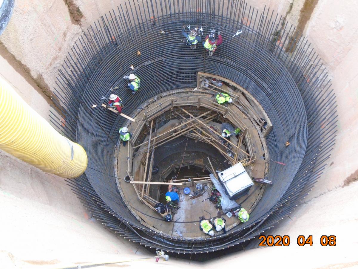
Mount Olivet Road NE Construction Site
There are two construction staging areas on Mount Olivet Road NE: Department of Public Works (DPW) parking lot on Mount Olivet Road; and the intersection of Mount Olivet Road and Capitol Avenue NE. In order to relieve chronic sewer flooding, DC Water will construct a diversion facility that will include a diversion chamber, a 25-foot diameter drop shaft, and other structures to convey flow from the existing sewer to the tunnel.

Click to view full-size image

Click to view full-size image

Click to view full-size image
W Street NE Construction Site
The W Street NE Construction Site is located on the Department of Public Works property south of W Street NE. DC Water will construct a ventilation control facility that will include a ventilation channel, a 45-foot diameter junction shaft, and other structures to regulate airflow throughout the tunnel system.

Click to view full-size image

Click to view full-size image

Click to view full-size image
Rhode Island Avenue NE Construction Site
The Rhode Island Avenue NE Construction Site is located on Rhode Island Avenue NE near the 8th Place intersection. In order to relieve chronic sewer flooding, DC Water will construct a diversion facility which will include a diversion chamber, a 25-foot diameter drop shaft, and other structures to convey flow from the existing sewer to the tunnel.

Click to view full-size image

Click to view full-size image

Click to view full-size image
4th Street NE Construction Site
At this site, construction will occur along 4th Street NE north of the Rhode Island Avenue NE intersection. In order to relieve chronic sewer flooding, DC Water will construct a diversion facility that will include a diversion chamber, a 20-foot diameter drop shaft, and other structures to convey flow from the existing sewer to the tunnel. The 4th Street Diversion Facility is designed to convey a peak flow rate of 457.2 million gallons per day to the Tunnel System.

Click to view full-size image

Click to view full-size image

Click to view full-size image
First Street Pumping Station Construction Site
The First Street Pumping Station Construction Site is located at the intersection of Thomas Street NW and First Street NW. The First Street Tunnel (FST) serves as a large storage tank for the Bloomingdale sewer system during large storm events. After the storm, the Pumping Station pumps the combined sewage out of the FST to the existing sewer system. Once the Northeast Boundary Tunnel (NEBT) is connected to the FST, the Pumping Station will be decommissioned and demolished. The NEBT will convey the combined sewage from the FST to the Blue Plains Wastewater Treatment Plant.

Click to view full-size image

Click to view full-size image

Click to view full-size image
T Street NW Construction Site
The T Street NW Construction Site is located at the intersection of T Street NW and Rhode Island Avenue NW. In order to relieve chronic sewer flooding, DC Water will construct a diversion facility which will include additional storm water inlets, a 15-foot diameter drop shaft, and other structures to convey surface runoff to the tunnel. The T Street Diversion Facility is designed to convey a peak flow rate of 116.1 million gallons per day to the Tunnel System.

Click to view full-size image

Click to view full-size image

Click to view full-size image
Florida Avenue NW Construction Site
Construction at this site will occur along 3rd Street NW and Florida Avenue NW. In order to relieve chronic sewer flooding, DC Water will construct a diversion facility that will include a diversion chamber, a 20-foot diameter drop shaft, and other structures to convey flow from the existing sewer to the tunnel. The Florida Avenue Diversion Facility is designed to convey a peak flow rate of 322.8 million gallons per day to the Tunnel System.

Click to view full-size image

Click to view full-size image

Click to view full-size image
R Street NW Construction Site
The R Street NW Construction Site is located within the triangular park bounded by 6th Street NW, R Street NW, and Rhode Island Avenue NW. In order to relieve chronic sewer flooding, DC Water will construct a diversion facility which will include a diversion chamber, a 38-foot diameter drop shaft, and other structures to convey flow from the existing sewer to the tunnel. The R Street Diversion Facility is designed to convey a peak flow rate of 264 million gallons per day to the Tunnel System.

Click to view full-size image

Click to view full-size image

Click to view full-size image


.jpg)