Materials and Technologies for the Tertiary Treatment of Produced Water Contaminated by Oil Impurities through Nonfibrous Deep-Bed Media: A Review

 ,
,
Abstract
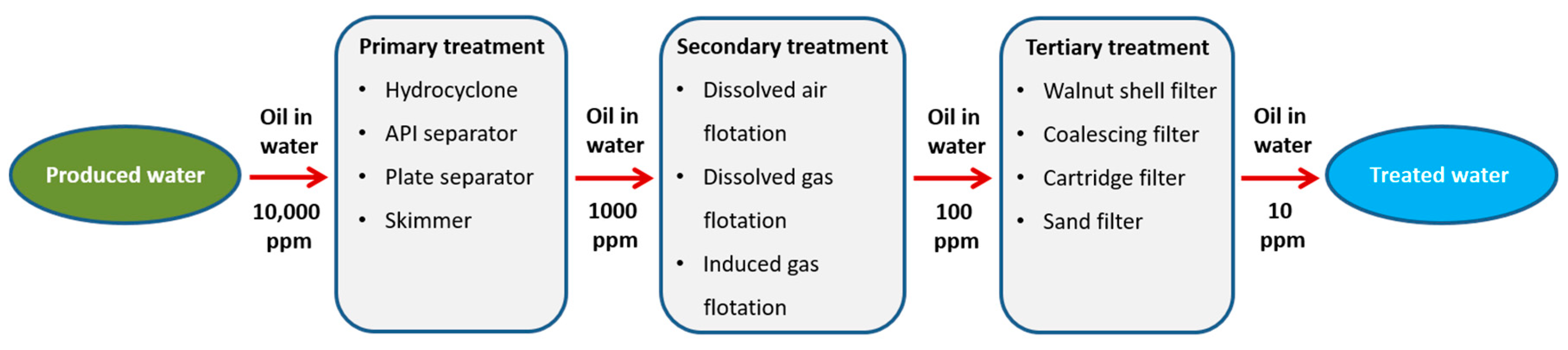
:1. Introduction
2. Emulsions and Surfactants
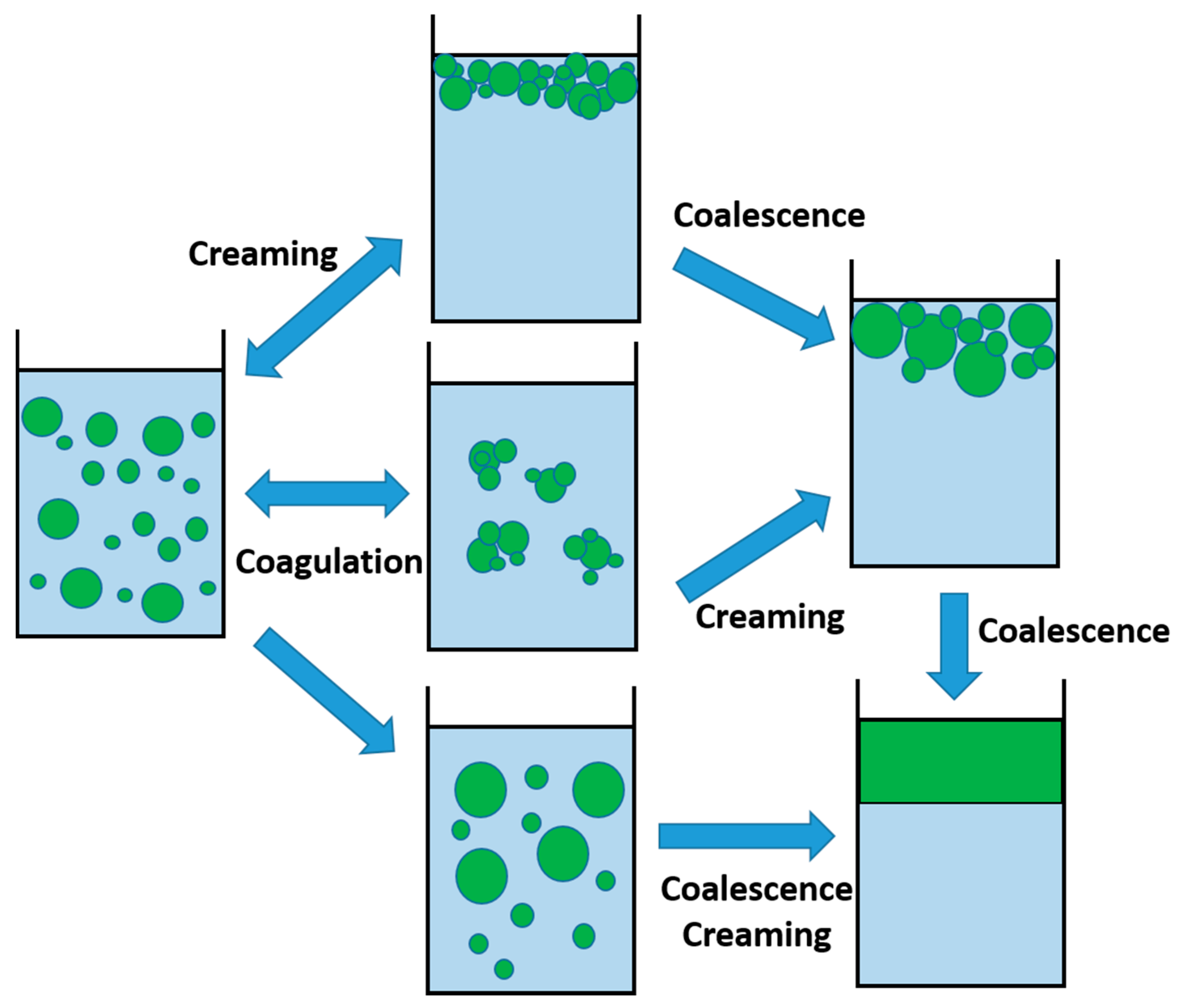
2.1. Emulsion Instabilities
2.1.1. Ostwald Ripening
2.1.2. Creaming (or Flotation)
2.1.3. Aggregation
2.1.4. Coalescence
3. Oil Sorption Media
3.1. Natural Materials
3.2. Nutshell Filters
3.3. Synthetic Materials Used for Oil Sorption in General
3.3.1. 3D Materials
3.3.2. Polyurethane (PU)
3.3.3. Melamine Formaldehyde (MF)
3.3.4. Polydimethylsiloxane (PDMS)
3.3.5. Natural Rubber
3.3.6. Polystyrene (PS)
3.3.7. Poly(styrene-divinylbenzene)
3.3.8. Carbon-Based Foams
3.3.9. Graphene-Based Sorbents
3.3.10. Carbon Aerogels
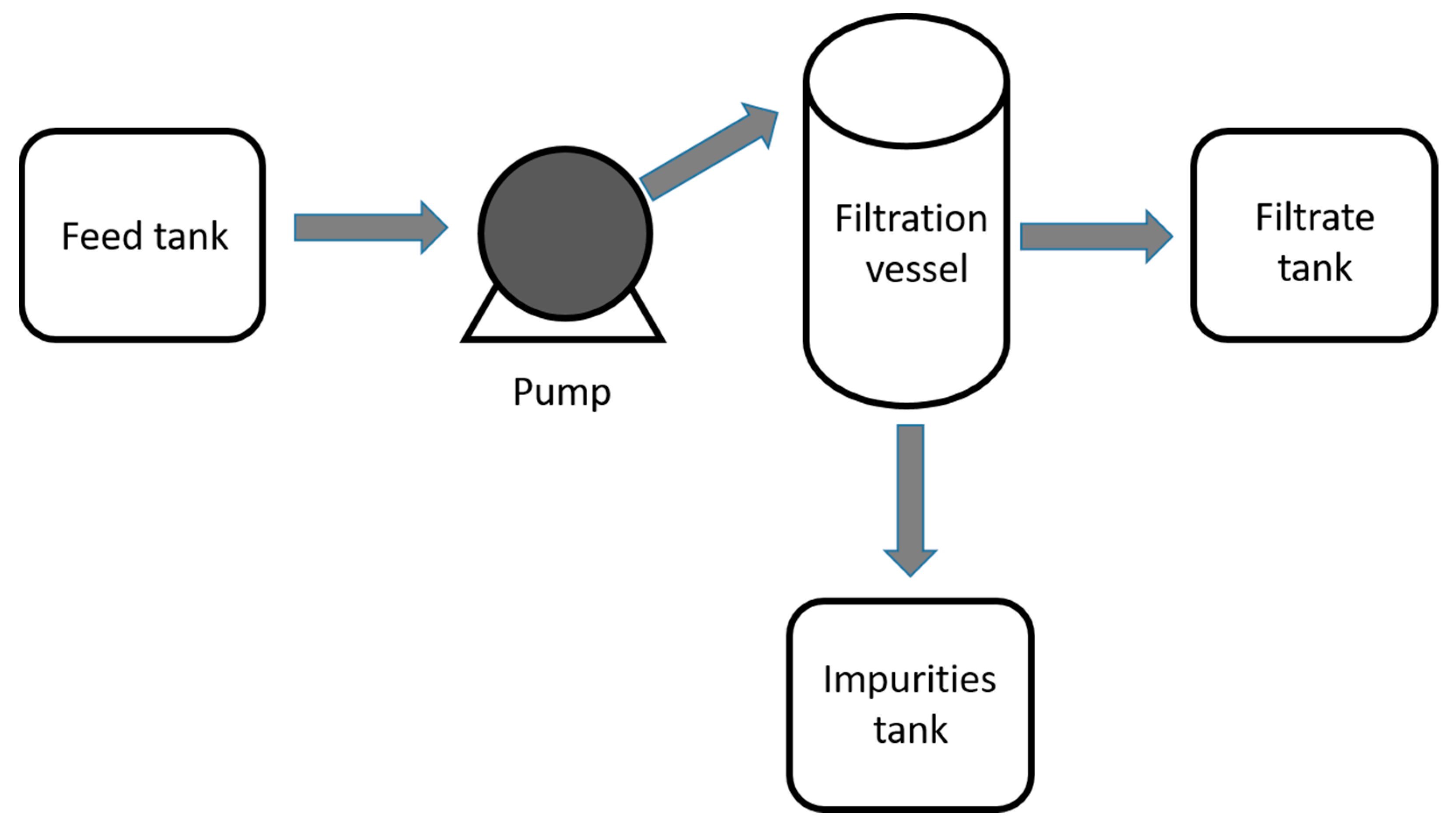
4. Laboratory Setups for Testing Oil/Water Deep-Bed Filtration
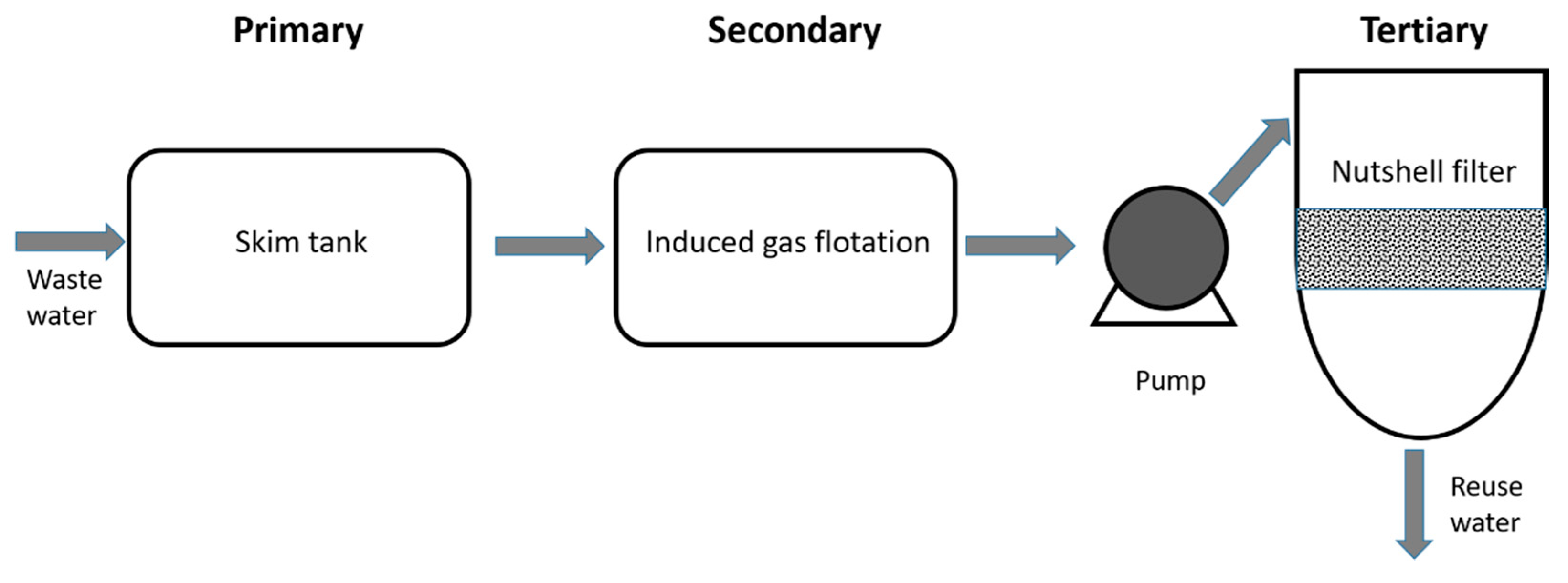
5. Industrial Setups for Testing Oil/Water Deep-Bed Filtration
6. Conclusions
Author Contributions
Funding
Conflicts of Interest
References
- Pintor, A.M.A.; Vilar, V.J.P.; Botelho, C.M.S.; Boaventura, R.A.R. Oil and grease removal from wastewaters: Sorption treatment as an alternative to state-of-the-art technologies. A critical review. Chem. Eng. J. 2016, 297, 229–255. [Google Scholar] [CrossRef]
- El-Samak, A.A.; Ponnamma, D.; Hassan, M.K.; Ammar, A.; Adham, S.; Al-Maadeed, M.A.A.; Karim, A. Designing flexible and porous fibrous membranes for oil water separation—A review of recent developments. Polym. Rev. 2020. [Google Scholar] [CrossRef]
- Ponnamma, D.; Nair, S.S.; Parangusan, H.; Hassan, M.K.; Adham, S.; Karim, A.; Al-Maadeed, M.A.A. White graphene-cobalt oxide hybrid filler reinforced polystyrene nanofibers for selective oil absorption. Polymers 2020, 12, 4. [Google Scholar] [CrossRef] [PubMed] [Green Version]
- Samanta, A.; Bera, A.; Ojha, K.; Mandal, A. Comparative studies on enhanced oil recovery by alkali-surfactant and polymer flooding. J. Pet. Explor. Prod. Technol. 2012, 2, 67–74. [Google Scholar] [CrossRef] [Green Version]
- Esmaeilzadeh, P.; Bahramian, A.; Fakhroueian, Z. Adsorption of anionic, cationic and nonionic surfactants on carbonate rock in presence of ZrO2 nanoparticles. Phys. Procedia 2011, 22, 63–67. [Google Scholar] [CrossRef] [Green Version]
- Gbadamosi, A.O.; Junin, R.; Manan, M.A.; Agi, A.; Yusuff, A.S. An overview of chemical enhanced oil recovery: Recent advances and prospects. Int. Nano Lett. 2019, 9, 171–202. [Google Scholar] [CrossRef] [Green Version]
- Patterson, J.W. Industrial Wastewater Treatment Technology, 2nd ed.; OSTI.GOV: Stoneham, MA, USA, 1985.
- Coonrod, C.L.; Ben Yin, Y.; Hanna, T.; Atkinson, A.J.; Alvarez, P.J.J.; Tekavec, T.N.; Reynolds, M.A.; Wong, M.S. Fit-for-purpose treatment goals for produced waters in shale oil and gas fields. Water Res. 2020, 173, 115467. [Google Scholar] [CrossRef]
- Al-Ghouti, M.A.; Al-Kaabi, M.A.; Ashfaq, M.Y.; Da’na, D.A. Produced water characteristics, treatment and reuse: A review. J. Water Process Eng. 2019, 28, 222–239. [Google Scholar] [CrossRef]
- Fakhru’l-Razi, A.; Pendashteh, A.; Abdullah, L.C.; Biak, D.R.A.; Madaeni, S.S.; Abidin, Z.Z. Review of technologies for oil and gas produced water treatment. J. Hazard. Mater. 2009, 170, 530–551. [Google Scholar] [CrossRef]
- Yu, L.; Han, M.; He, F. A review of treating oily wastewater. Arab. J. Chem. 2017, 10, S1913–S1922. [Google Scholar] [CrossRef] [Green Version]
- Doshi, B.; Sillanpää, M.; Kalliola, S. A review of bio-based materials for oil spill treatment. Water Res. 2018, 135, 262–277. [Google Scholar] [CrossRef] [PubMed]
- Roques, H.; Aurelle, Y. Oil-water separations oil recovery and oily wastewater treatment. In New Developments in Industrial Wastewater Treatment; Springer: Dordrecht, The Netherlands, 1991; pp. 155–174. [Google Scholar]
- Nemani, S.K.; Annavarapu, R.K.; Mohammadian, B.; Raiyan, A.; Heil, J.; Haque, M.A.; Abdelaal, A.; Sojoudi, H. Surface modification of polymers: Methods and applications. Adv. Mater. Interfaces 2018, 5, 1801247. [Google Scholar] [CrossRef]
- Yamashita, Y.; Miyahara, R.; Sakamoto, K. Emulsion and emulsification technology. In Cosmetic Science and Technology: Theoretical Principles and Applications; Elsevier Inc.: Amsterdam, The Netherlands, 2017; pp. 489–506. ISBN 9780128020548. [Google Scholar]
- Walstra, P. Physical Chemistry of Foods; Marcel Dekker: New York, NY, USA, 2003; ISBN 9780824793555. [Google Scholar]
- Giermanska, J.; Thivilliers, F.; Backov, R.; Schmitt, V.; Drelon, N.; Leal-Calderon, F. Gelling of oil-in-water emulsions comprising crystallized droplets. Langmuir 2007, 23, 4792–4799. [Google Scholar] [CrossRef] [PubMed]
- Liu, W.; Sun, D.; Li, C.; Liu, Q.; Xu, J. Formation and stability of paraffin oil-in-water nano-emulsions prepared by the emulsion inversion point method. J. Colloid Interface Sci. 2006, 303, 557–563. [Google Scholar] [CrossRef] [PubMed]
- Fredrick, E.; Walstra, P.; Dewettinck, K. Factors governing partial coalescence in oil-in-water emulsions. Adv. Colloid Interface Sci. 2010, 153, 30–42. [Google Scholar] [CrossRef]
- Goodarzi, F.; Zendehboudi, S. A comprehensive review on emulsions and emulsion stability in chemical and energy industries. Can. J. Chem. Eng. 2019, 97, 281–309. [Google Scholar] [CrossRef] [Green Version]
- Krasiński, A. Separation of oil-in-water emulsions using polymer coalescence structures. Environ. Prot. Eng. 2020, 42. [Google Scholar] [CrossRef]
- Luo, H.-Q.; Bai, Z.-S. Investigation of O/W emulsion separation and redispersion using fibrous PTFE bed coalescer. Sep. Sci. Technol. 2019, 54, 1221–1232. [Google Scholar] [CrossRef]
- Kundu, P.; Mishra, I.M. Removal of emulsified oil from oily wastewater (oil-in-water emulsion) using packed bed of polymeric resin beads. Sep. Purif. Technol. 2013, 118, 519–529. [Google Scholar] [CrossRef]
- Chen, C.; Weng, D.; Mahmood, A.; Chen, S.; Wang, J. Separation mechanism and construction of surfaces with special wettability for Oil/Water separation. ACS Appl. Mater. Interfaces 2019, 11, 11006–11027. [Google Scholar] [CrossRef]
- Dickhout, J.M.; Moreno, J.; Biesheuvel, P.M.; Boels, L.; Lammertink, R.G.H.; de Vos, W.M. Produced water treatment by membranes: A review from a colloidal perspective. J. Colloid Interface Sci. 2017, 487, 523–534. [Google Scholar] [CrossRef] [PubMed]
- Bradford, S.A.; Torkzaban, S.; Simunek, J. Modeling colloid transport and retention in saturated porous media under unfavorable attachment conditions. Water Resour. Res. 2011, 47. [Google Scholar] [CrossRef]
- Rawlins, C.H. Experimental study on oil and solids removal in nutshell filters for produced water treatment. In Proceedings of the SPE Western Regional Meeting, Garden Grove, CA, USA, 22–26 April 2018. [Google Scholar]
- Kamp, J.; Villwock, J.; Kraume, M. Drop coalescence in technical liquid/liquid applications: A review on experimental techniques and modeling approaches. Rev. Chem. Eng. 2017, 33, 1–47. [Google Scholar] [CrossRef] [Green Version]
- Danov, K.D.; Kralchevsky, P.A.; Ivanov, I.B. Encyclopedic Handbook of Emulsion Technology; CRC Press: Boca Raton, FL, USA, 2001. [Google Scholar]
- Akiyama, T. Oil Absorbers and Methods of Using Them. U.S. Patent 4172039, 23 October 1979. [Google Scholar]
- De Leij, F.A.A.M.; Stratford, J.; Hutchings, T. Oil Absorbent Composition. U.S. Patent US 2014/0038266A1, 6 February 2014. [Google Scholar]
- Ji, H.; Xie, W.; Liu, W.; Liu, X.; Zhao, D. Sorption of dispersed petroleum hydrocarbons by activated charcoals: Effects of oil dispersants. Environ. Pollut. 2020, 256, 113416. [Google Scholar] [CrossRef] [PubMed]
- Warrenchak, J.F.; Phelan, E.F. Treated Silica for Oil Absorption. U.S. Patent US5037557A, 15 August 1990. [Google Scholar]
- Skillicorn, P. Methods for Treatment of Wastewater with Powdered Natural Lignocellulosic Material. U.S. Patent US7481934B2, 27 January 2009. [Google Scholar]
- Huang, X.; Lim, T.T. Performance and mechanism of a hydrophobic-oleophilic kapok filter for oil/water separation. Desalination 2006, 190, 295–307. [Google Scholar] [CrossRef]
- Lim, T.T.; Huang, X. Evaluation of hydrophobicity/oleophilicity of kapok and its performance in oily water filtration: Comparison of raw and solvent-treated fibers. Ind. Crops Prod. 2007, 26, 125–134. [Google Scholar] [CrossRef]
- Dong, T.; Cao, S.; Xu, G. Highly efficient and recyclable depth filtrating system using structured kapok filters for oil removal and recovery from wastewater. J. Hazard. Mater. 2017, 321, 859–867. [Google Scholar] [CrossRef]
- Zheng, Y.; Wang, J.; Zhu, Y.; Wang, A. Research and application of kapok fiber as an absorbing material: A mini review. J. Environ. Sci. 2014. [Google Scholar] [CrossRef]
- Hirs, G. Method and Apparatus for Rejuvenating a Bed of Granular Filter Medium. U.S. Patent 3953333A, 24 April 1975. [Google Scholar]
- Rawlins, C.H.; Sadeghi, F. Experimental study on oil removal in nutshell filters for produced-water treatment. SPE Prod. Oper. 2018, 33, 145–153. [Google Scholar] [CrossRef]
- Srinivasan, A.; Viraraghavan, T. Removal of oil by walnut shell media. Bioresour. Technol. Technol. 2008, 99, 8217–8220. [Google Scholar] [CrossRef]
- Yang, Y.; Zhang, X.; Wang, Z. Oilfield produced water treatment with surface-modified fiber ball media filtration. Water Sci. Technol. 2002, 46, 165–170. [Google Scholar] [CrossRef] [PubMed]
- Rahman, S.S. Evaluation of filtering efficiency of walnut granules as deep-bed filter media. J. Pet. Sci. Eng. 1992, 7, 239–246. [Google Scholar] [CrossRef]
- Adham, S.; Hussain, A.; Minier-Matar, J.; Janson, A.; Sharma, R. Membrane applications and opportunities for water management in the oil & gas industry. Desalination 2018, 440, 2–17. [Google Scholar]
- Knapik, E.; Stopa, J. Fibrous deep-bed filtration for oil/water separation using sunflower pith as filter media. Ecol. Eng. 2018, 121, 44–52. [Google Scholar] [CrossRef]
- Topolkaraev, V.A.; McEneany, R.J.; Scholl, N.T.; Eby, T. Oil Absorbing Material and Processes of Recycling Absorbent Articles to Produce the Same. U.S. Patent 8550386B2, 8 October 2013. [Google Scholar]
- Eriksen, K.E. Oil Absorbent. U.S. Patent US3591524A, 6 July 1971. [Google Scholar]
- Yoshiyuki, H.; Toru, I.; Tomoki, G.; Takakiyo, G.; Toru, U.; Kenji, R. Oil- Absorbent Polymer and Use Therefor. U.S. Patent EP0441512A2, 14 August 1991. [Google Scholar]
- Jenkins, F.W. Process for Breaking Emulsions of the Oil-In-Water Class. U.S. Patent 3090759, 21 May 1963. [Google Scholar]
- Neukomm, H.O.; Graham, H.E. Process for Producing Thermoplastic Filter Material. U.S. Patent 3617590, 2 November 1971. [Google Scholar]
- Burt, W.E. Thermoplastic Filter Media and Filtering Process. U.S. Patent 3842006, 15 October 1974. [Google Scholar]
- Tulley, F.T.; Harris, B.C. Process and Apparatus for Fluid Treatment. U.S. Patent 3544457, 1 December 1970. [Google Scholar]
- Hirs, G.; Wykoff, R.H. Method of and Apparatus for Filtering. U.S. Patent 3557955, 26 January 1971. [Google Scholar]
- Dobson, R.D. Filter Comprising a Bed of Buoyant and a Bed of No-Bouyant Sand. U.S. Patent 3471025, 7 October 1969. [Google Scholar]
- Chisholm, J.R. Filtering Device. U.S. Patent 3182803, 27 May 1965. [Google Scholar]
- Hirs, G. Deep Bed Filtration System. International Patent Application No. WO2002032540A1, 25 April 2002. [Google Scholar]
- D’Alelio, G.F. Production of Synthetic Polymeric Compositions Comprising Sulfonated Polymerizates of Poly-Vinyl Aryl Compounds and Treatment of Liquid Media Therewith. U.S. Patent 2366007, 11 August 1944. [Google Scholar]
- Harris, R.H.; Lamica, J.S. Sintered-Glass-Granule Filter Medium. U.S. Patent 4225443A, 30 September 1980. [Google Scholar]
- Guselnikova, O.; Barras, A.; Addad, A.; Sviridova, E.; Szunerits, S.; Postnikov, P.; Boukherroub, R. Magnetic polyurethane sponge for efficient oil adsorption and separation of oil from oil-in-water emulsions. Sep. Purif. Technol. 2020, 240, 116627. [Google Scholar] [CrossRef]
- Li, H.; Liu, L.; Yang, F. Oleophobic polyurethane foams for oil spill cleanup.pdf. Procedia Environ. Sci. 2013, 18, 528–533. [Google Scholar] [CrossRef] [Green Version]
- Wu, D.; Fang, L.; Qin, Y.; Wu, W.; Mao, C.; Zhu, H. Oil sorbents with high sorption capacity, oil/water selectivity and reusability for oil spill cleanup. Mar. Pollut. Bull. 2014, 84, 263–267. [Google Scholar] [CrossRef]
- Su, C. Highly hydrophobic and oleophilic foam for selective absorption. Appl. Surf. Sci. 2009, 256, 1413–1418. [Google Scholar] [CrossRef]
- Pan, Y.; Zhan, J.; Pan, H.; Yuan, B.; Wang, W.; Song, L.; Hu, Y. A facile method to fabricate superoleophilic and hydrophobic polyurethane foam for oil-water separation. Mater. Lett. 2015, 159, 345–348. [Google Scholar] [CrossRef]
- Kong, L.; Li, Y.; Qiu, F.; Zhang, T.; Guo, Q.; Zhang, X.; Yang, D.; Xu, J.; Xue, M. Fabrication of hydrophobic and oleophilic polyurethane foam sponge modified with hydrophobic Al2O3 for oil/water separation. J. Ind. Eng. Chem. 2018, 58, 369–375. [Google Scholar] [CrossRef]
- Ruan, C.; Ai, K.; Li, X.; Lu, L. A superhydrophobic sponge with excellent absorbency and flame retardancy. Angew. Chem. Int. Ed. 2014, 53, 5556–5560. [Google Scholar] [CrossRef] [PubMed]
- Gao, H.; Sun, P.; Zhang, Y.; Zeng, X.; Wang, D.; Zhang, Y.; Wang, W.; Wu, J. A two-step hydrophobic fabrication of melamine sponge for oil absorption and oil/water separation. Surf. Coat. Technol. 2018, 339, 147–154. [Google Scholar] [CrossRef]
- Yin, Z.; Li, Y.; Song, T.; Bao, M.; Li, Y.; Lu, J.; Li, Y. An environmentally benign approach to prepare superhydrophobic magnetic melamine sponge for effective oil/water separation. Sep. Purif. Technol. 2020, 236, 116308. [Google Scholar] [CrossRef]
- Zhou, J.; Zhang, Y.; Yang, Y.; Chen, Z.; Jia, G.; Zhang, L. Silk fibroin-graphene oxide functionalized melamine sponge for efficient oil absorption and oil/water separation. Appl. Surf. Sci. 2019, 497, 143762. [Google Scholar] [CrossRef]
- Shin, J.H.; Heo, J.H.; Jeon, S.; Park, J.H.; Kim, S.; Kang, H.W. Bio-inspired hollow PDMS sponge for enhanced oil–water separation. J. Hazard. Mater. 2019, 365, 494–501. [Google Scholar] [CrossRef] [PubMed]
- Lazim, A.M.; Musbah, D.L.; Chin, C.C.; Abdullah, I.; Mustapa, M.H.A.; Azfaralariff, A. Oil removal from water surface using reusable and absorptive foams via simple fabrication of liquid natural rubber (LNR). Polym. Test. 2019, 73, 39–50. [Google Scholar] [CrossRef]
- Yu, L.; Hao, G.; Xiao, L.; Yin, Q.; Xia, M.; Jiang, W. Robust magnetic polystyrene foam for high efficiency and removal oil from water surface. Sep. Purif. Technol. 2017, 173, 121–128. [Google Scholar] [CrossRef]
- Zhang, N.; Jiang, W.; Wang, T.; Gu, J.; Zhong, S.; Zhou, S.; Xie, T.; Fu, J. Facile preparation of magnetic poly(styrene-divinylbenzene) foam and its application as an oil absorbent. Ind. Eng. Chem. Res. 2015, 54, 11033–11039. [Google Scholar] [CrossRef]
- Gupta, S.; Tai, N-H. Carbon materials as oil sorbents: A review on the synthesis and performance. J. Mater. Chem. A 2016, 4, 1550–1565. [Google Scholar] [CrossRef]
- Zhu, Q.; Chu, Y.; Wang, Z.; Chen, N.; Lin, L.; Liu, F.; Pan, Q. Robust superhydrophobic polyurethane sponge as a highly reusable oil-absorption material. J. Mater. Chem. A 2013, 1, 5386–5393. [Google Scholar] [CrossRef]
- Zhu, Q.; Tao, F.; Pan, Q. Fast and selective removal of oils from water surface via highly hydrophobic core-shell Fe2O3@C nanoparticles under magnetic field. ACS Appl. Mater. Interfaces 2010. [Google Scholar] [CrossRef] [PubMed]
- Qiua, S.; Jiang, B.; Zheng, X.; Zheng, J.; Zhu, C.; Wu, M. Hydrophobic and fire-resistant carbon monolith from melamine sponge: A recyclable sorbent for oil–water separation. Carbon 2015, 84, 551–559. [Google Scholar] [CrossRef]
- Bhardwaj, N.; Bhaskarwar, A.N. A review on sorbent devices for oil-spill control. Environ. Pollut. 2018, 243, 1758–1771. [Google Scholar] [CrossRef] [PubMed]
- Kayvani Fard, A.; Mckay, G.; Manawi, Y.; Malaibari, Z.; Hussien, M.A. Outstanding adsorption performance of high aspect ratio and super-hydrophobic carbon nanotubes for oil removal. Chemosphere 2016, 164, 142–155. [Google Scholar] [CrossRef] [PubMed]
- Zhang, T.; Li, Z.; Lü, Y.; Liu, Y.; Yang, D.; Li, Q.; Qiu, F. Recent progress and future prospects of oil-absorbing materials. Chin. J. Chem. Eng. 2019, 27, 1282–1295. [Google Scholar] [CrossRef]
- Gui, X.; Wei, J.; Wang, K.; Cao, A.; Zhu, H.; Jia, Y.; Shu, Q.; Wu, D. Carbon nanotube sponges. Adv. Mater. 2010, 22, 617–621. [Google Scholar] [CrossRef]
- Gui, X.; Zeng, Z.; Lin, Z.; Gan, Q.; Xiang, R.; Zhu, Y.; Cao, A.; Tang, Z. Magnetic and highly recyclable macroporous carbon nanotubes for spilled oil sorption and separation. ACS Appl. Mater. Interfaces 2013, 5, 5845–5850. [Google Scholar] [CrossRef]
- Bi, H.; Xie, X.; Yin, K.; Zhou, Y.; Wan, S.; He, L.; Xu, F.; Banhart, F.; Sun, L.; Ruoff, R.S. Spongy graphene as a highly efficient and recyclable sorbent for oils and organic solvents. Adv. Funct. Mater. 2012, 22, 4421–4425. [Google Scholar] [CrossRef]
- Li, J.; Meng, H.; Xie, S.; Zhang, B.; Li, J.; Li, L.; Ma, H.; Zhang, J.; Yu, M. Ultra-light, compressible and fire-resistant graphene aerogel as a highly efficient and recyclable absorbent for organic liquids. J. Mater. Chem. A 2014, 2, 2934–2941. [Google Scholar] [CrossRef]
- Zhao, Y.; Hu, C.; Hu, Y.; Cheng, H.; Shi, G.; Qu, L. A versatile, ultralight, nitrogen-doped graphene framework. Angew. Chem. Int. Ed. 2012, 51, 11371–11375. [Google Scholar] [CrossRef]
- He, Y.; Liu, Y.; Wu, T.; Ma, J.; Wang, X.; Gong, Q.; Kong, W.; Xing, F.; Liu, Y.; Gao, J. An environmentally friendly method for the fabrication of reduced graphene oxide foam with a super oil absorption capacity. J. Hazard. Mater. 2013, 260, 796–805. [Google Scholar] [CrossRef] [PubMed]
- Li, Y.-Q.; Samad, Y.A.; Polychronopoulou, K.; Alhassan, S.M.; Liao, K. Carbon aerogel from winter melon for highly efficient and recyclable oils and organic solvents absorption. ACS Sustain. Chem. Eng. 2014, 2, 1492–1497. [Google Scholar] [CrossRef]
- Wu, Z.Y.; Li, C.; Liang, H.W.; Chen, J.F.; Yu, S.H. Ultralight, flexible, and fire-resistant carbon nanofiber aerogels from bacterial cellulose. Angew. Chem. Int. Ed. 2013, 52, 2925–2929. [Google Scholar] [CrossRef] [PubMed]
- Wu, Z.Y.; Li, C.; Liang, H.W.; Zhang, Y.N.; Wang, X.; Chen, J.F.; Yu, S.H. Carbon nanofiber aerogels for emergent cleanup of oil spillage and chemical leakage under harsh conditions. Sci. Rep. 2014, 3, 1–6. [Google Scholar] [CrossRef]
- Hu, H.; Zhao, Z.; Gogotsi, Y.; Qiu, J. Compressible carbon nanotube-graphene hybrid aerogels with superhydrophobicity and superoleophilicity for oil sorption. Environ. Sci. Technol. Lett. 2014, 1, 214–220. [Google Scholar] [CrossRef]
- Dong, X.; Chen, J.; Ma, Y.; Wang, J.; Chan-Park, M.B.; Liu, X.; Wang, L.; Huang, W.; Chen, P. Superhydrophobic and superoleophilic hybrid foam of graphene and carbon nanotube for selective removal of oils or organic solvents from the surface of water. Chem. Commun. 2012, 48, 10660–10662. [Google Scholar] [CrossRef]
- Sun, H.; Xu, Z.; Gao, C. Multifunctional, ultra-flyweight, synergistically assembled carbon aerogels. Adv. Mater. 2013, 25, 2554–2560. [Google Scholar] [CrossRef]
- Jegatheesan, V.; Vigneswaran, S. Deep bed filtration: Mathematical models and observations. Crit. Rev. Environ. Sci. Technol. 2005, 35, 515–569. [Google Scholar] [CrossRef]
- Cambiella, Á.; Ortea, E.; Ríos, G.; Benito, J.M.; Pazos, C.; Coca, J. Treatment of oil-in-water emulsions: Performance of a sawdust bed filter. J. Hazard. Mater. 2006, 131, 195–199. [Google Scholar] [CrossRef]
- Dobre, T.; Zicman, L.R.; Pârvulescu, O.C.; Neacşu, E.; Ciobanu, C.; Drăgolici, F.N. Species removal from aqueous radioactive waste by deep-bed filtration. Environ. Pollut. 2018, 241, 303–310. [Google Scholar] [CrossRef]
- Pintor, A.M.A.; Martins, A.G.; Souza, R.S.; Vilar, V.J.P.; Botelho, C.M.S.; Boaventura, R.A.R. Treatment of vegetable oil refinery wastewater by sorption of oil and grease onto regranulated cork—A study in batch and continuous mode. Chem. Eng. J. 2015, 268, 92–101. [Google Scholar] [CrossRef]
- Wykoff, R.H.; Livonia, M.; Hirs, G. Metod of and Apparatus for Filtering. U.S. Patent 113,550,774, 2 March 1969. [Google Scholar]
- Wykoff, R.H.; Livonia, M.; Hirs, G. Metod of and Apparatus for Filtering. U.S. Patent 113,557,955, 9 January 1968. [Google Scholar]
- Lerner, M.; Erlich, G. Particulate Filter Media Having a Gradient of Removal Ratings. U.S. Patent 3704786, 12 May 1972. [Google Scholar]
- Rice, A.H.; Conley, W.R. Filter and Methods Making Same. U.S. Patent 3343680, 17 February 1967. [Google Scholar]
- Hirs, G. Method of Filtering Oil from Liquids. U.S. Patent US3992291A, 6 May 1975. [Google Scholar]
- Dean, I.A. Liquid Treatment Media Regeneration Apparatus and Process. U.S. Patent 6287474B1, 27 July 1998. [Google Scholar]
- Hensley, C.J. Filter System and Scrubber. U.S. Patent 4966698A, 9 January 1987. [Google Scholar]
- LeeColin, D.W.; Bateman, T.W. A Method and Device for Cleaning Non-Fixed Media Filters. International Patent Application No. CA2689047A1, 21 August 2007. [Google Scholar]
- Hensley, J.L. System and Method for Backwashing Multiple Filtration Vessels. U.S. Patent 5833867A, 1 December 1995. [Google Scholar]


| Physical State | Diameter Range | Description |
|---|---|---|
| Free oil | >150 μm | Droplets that rise quickly to the surface in quiescent conditions due to an imbalance of forces caused by the differential density between oil and water |
| Dispersed oil | 20–150 μm | Droplets stabilized by electric charges and other interparticle forces |
| Emulsified oil | 20 μm | Droplets stabilized by the chemical action of surface-active agents |
| Soluble or “dissolved” oil | <5 μm | Dissolved or very finely dispersed droplets |
| “Oil-wet solids” | Suspended solids with oil adhered to their surface |
| Media | Oil/Water Mixture | Sorption Capacity | Inlet | Outlet | Reference |
|---|---|---|---|---|---|
| Charcoal | Hydrocarbons in water | 10.90 mg/g | 100 ppm | below 1 ppm | [32] |
| Silica | High molecular weight alcohols diesel fuel, gasoline, heating and motor oil water emulsions | 10 g/g | N/A | below 1 ppm | [33] |
| Kapok | Vegetable oil or diesel polluted water | 32.31 g/g | 11,500–13,150 ppm | 126 | [37] |
| Kapok | diesel oil | N/A | 2.5 wt.% | 99% | [36] |
| Kapok | Diesel and hydraulic oil | N/A | 5 to 15 wt.% | Over 99% | [35] |
| Sawdust | Metalworking fluid | 3 wt.% | 99% | [45] | |
| Walnut shell | Mineral oil, vegetable oil, DoALL Bright-Edge oil, | 0.56 to 0.74 g/g | N/A | N/A | [41] |
| Black walnut shell | Hydrocarbons | N/A | 100 ppm | Below 5 ppm | [40] |
| Walnut granules | Hydrocarbons | N/A | 50–100 ppm | 2–5 ppm | [43] |
| Polymer | Treatment | Sorption Capacity (g/g) | Desorption Method | Water Contact Angle (°) | Pore Size (μm) | Reference |
|---|---|---|---|---|---|---|
| PU | Surface functionalization and introduction of magnetic nanoparticles | Chloroform: 77.2 Xylene: 58.3 Pump oil: 53.1 | Mechanical squeezing | 168 | N/A | [59] |
| PU | Graft copolymerization | Diesel: 46.98 Kerosene: 41.42 | Mechanical squeezing | N/A | N/A | [60] |
| PU | Surface treatment by immersion in SiO2 sol and subsequently gasoline | Motor oil: 103 Peanut oil: 108 Diesel: 95 | Mechanical squeezing | 126 | N/A | [61] |
| PU | Superhydrophobic surface coating | Drying at 30 °C | 152 | N/A | [62] | |
| PU | Layer-by-layer self-assembly of chitosan and titanate nanotubes | Diesel oil: 32 Soybean oil: 30 | Mechanical squeezing | 128 | N/A | [63] |
| PU | Impregnation with Al2O3 | Chloroform: 39 | Rinsing with ethanol, squeezing and drying | 140 | N/A | [64] |
| MF | Dip-coating and grafting | Pump oil: 100 Soybean oil: 102 | Mechanical squeezing and solvent extraction | 163 | N/A | [65] |
| MF | Surface modification: Silica nanoparticle adsorption and silanization covering | Hexane: 60 Toluene: 77 | Mechanical squeezing | N/A | N/A | [66] |
| MF | In situ synthesis of Fe3O4 particles and dip coating of Candelilla wax (CW). | Cyclohexane: 55 Tetradecane: 104 | Rinsing with ethanol and drying | 158 | N/A | [67] |
| MF | Impregnation with GO | Silicon oil: 54 Chloroform: 76.4 Liquid paraffin 45.2 | Mechanical squeezing | 130 | N/A | [68] |
| PDMS | 3D printing using sacrificial molds for precise control of pore size | Diesel: 800% | Rinsing with ethanol, squeezing and drying | 143 | 400 | [69] |
| Natural rubber foam | Vulcanization and cross-linking | Petrol: 7 Kerosene: 6 Diesel: 5.5 | Mechanical squeezing | 95 | 639 | [70] |
| PS | Impregnation with oleic acid-coated Fe3O4 | Diesel oil: 14.41 Lubricating oil: 17.83 | Mechanical squeezing | 141 | 500 | [71] |
| Poly(St-DVB) | Incorporating carbonyl iron powder to obtain a composite | Diesel oil: 22.7 Gasoline: 21.9 | Centrifugation | 142 | N/A | [72] |
| Preparation Method | Density (mg/cm3) | Sorption Capacity (g/g) | Absorption Rate (g−1 s−1) | WCA (°) | Porosity | Pore Size | Desorption | Reference | |
|---|---|---|---|---|---|---|---|---|---|
| CNT sponge | Chemical vapor deposition (CVD) | 5–10 | Diesel: 140 | N/A | 156 | N/A | 80 nm | Mechanical compression | [79] |
| Magnetic CNT sponge | CVD | 15 | Diesel: 56 Gas oil: 49 | N/A | 140 | 99% | N/A | Heat treatment | [80] |
| Graphene sponge | Shape molding | 12 ± 5 | Lubricating oil: 68.5 | Dodecane: 0.57 | 114 | N/A | N/A | Heat treatment | [81] |
| Graphene aerogel | Freeze-drying | 4.4–7.9 | CCl4: 250 | 27 | 150 | 99.6% | 50 μm | Mechanical compression | [82] |
| Nitrogen-doped graphene framework | Freeze-drying and annealing | 2.1 ± 0.3 | Gasoline: 600 | 41.7 | N/A | N/A | N/A | Direct combustion in air | [83] |
| Reduced graphene oxide foam | Freeze-drying | N/A | Diesel oil: 110 Pump oil: 118 | N/A | 135 | N/A | 50 μm | Heat treatment | [84] |
| Carbon aerogel | Pyrolysis of winter melon | 48 | 16–50 | N/A | 135 | 97.5% | 200 μm | Distillation | [85] |
| Carbon aerogel | Pyrolysis of bacterial cellulose | 4–6 | 106–312 | N/A | 128 | 99.7% | N/A | Direct combustion in air | [86] |
| Carbon aerogel | Freeze-drying and pyrolysis | 10 | Gasoline: 61.14 Diesel oil: 74.82 Pump oil: 86.34 | N/A | 135 | 99% | N/A | Drying or direct combustion | [87] |
| CNT-Graphene hybrid aerogel | Microwave irradiation | N/A | Pump oil: 138 Diesel: 120 Gasoline: 110 | N/A | >150 | 99% | N/A | Mechanical compression | [88] |
| CNT-Graphene hybrid 3D foam | CVD | 6.92 | Compressor oil: 90 Sesame oil: 105 | N/A | 152 | N/A | N/A | Oven drying | [89] |
| Carbon aerogel | Cryodessication | 0.75 | Crude oil: 289 Motor oil: 341 Vegetable oil: 41 | Toluene: 68.8 | 132.9 | 99.9% | 123 nm | Mechanical extrusion or heating | [90] |
| Bed Setup | Media | Oil/Water Mixture | Efficiency | Flow of Oil/Water Mixture | Reference |
|---|---|---|---|---|---|
| 10-cm-long glass column, internal diameter 2.71 cm, volume 57.68 cm3 | kapok | 5 to 15 wt.% diesel and hydraulic oil mixtures in water | 99% | 12.57 kPa | [35] |
| 10-cm-long glass column, internal diameter 2.71 cm, volume 57.68 cm3 | kapok | 11.5 to 13.2 g/L vegetable oil or diesel and tap water | 99% | sprayed | [37] |
| 1.5 L cylindrical acrylic reactor | regranulated cork | 200 ppm refined sunflower oil wastewater | Below 15 ppm | flow rate of 10 mL/min by a peristaltic pump | [95] |
| 2 L container | sunflower pith | crude oil, gasoline, diesel oil, and motor oil (0.1 to 20 g/L) | 80% | downflow direction with a peristaltic pump | [45] |
| Phar-macia Biotech column model XK26/20, 0.2 m long | Sawdust | 3 vol.% cutting oil | 99% | 0.5 bar | [92] |
| 4-inch-diameter, 48-inch-long PVC column | walnut shell and pecan media | 50–100 ppm crude oil | Below 5 ppm | peristaltic pump | [91] |
Publisher’s Note: MDPI stays neutral with regard to jurisdictional claims in published maps and institutional affiliations. |
© 2020 by the authors. Licensee MDPI, Basel, Switzerland. This article is an open access article distributed under the terms and conditions of the Creative Commons Attribution (CC BY) license (http://creativecommons.org/licenses/by/4.0/).
Share and Cite
Sobolciak, P.; Popelka, A.; Tanvir, A.; Al-Maadeed, M.A.; Adham, S.; Krupa, I. Materials and Technologies for the Tertiary Treatment of Produced Water Contaminated by Oil Impurities through Nonfibrous Deep-Bed Media: A Review. Water 2020, 12, 3419. https://doi.org/10.3390/w12123419
Sobolciak P, Popelka A, Tanvir A, Al-Maadeed MA, Adham S, Krupa I. Materials and Technologies for the Tertiary Treatment of Produced Water Contaminated by Oil Impurities through Nonfibrous Deep-Bed Media: A Review. Water. 2020; 12(12):3419. https://doi.org/10.3390/w12123419
Chicago/Turabian StyleSobolciak, Patrik, Anton Popelka, Aisha Tanvir, Mariam A Al-Maadeed, Samer Adham, and Igor Krupa. 2020. "Materials and Technologies for the Tertiary Treatment of Produced Water Contaminated by Oil Impurities through Nonfibrous Deep-Bed Media: A Review" Water 12, no. 12: 3419. https://doi.org/10.3390/w12123419