
Investigation on Hydraulic Characteristics of Turbine-Type Manhole Cover


Department of Hydraulic Engineering, College of Civil Engineering and Architecture, Zhejiang University, Hangzhou 310058, China
*
Author to whom correspondence should be addressed.
Water 2021, 13(11), 1530; https://doi.org/10.3390/w13111530
Submission received: 19 April 2021
/
Revised: 26 May 2021
/
Accepted: 26 May 2021
/
Published: 29 May 2021
(This article belongs to the Section Hydraulics and Hydrodynamics)
Abstract
:Manhole cover is an important device of urban drainage infrastructures. The hydraulic characteristics of turbine-type manhole covers were studied through numerical simulations and physical experiments. The flow field characteristics and water surface were investigated. The drainage process is divided into two parts: free flow regime and submerged flow regime. Numerical and experimental results are in good agreement. It is indicated that the depth of water is constant in the later stage of unstable free drainage, while it changes with time and determines the discharge under the subsequent unstable submerged drainage condition. The influence of the depth on discharge is mainly reflected in the submerged drainage stage, in which period the discharge is linearly related to the square root of the depth. While in free flow regime, the discharge is affected by volume fraction of water with second order. The correlation between the depth and the discharge in the process of submerged flow is proposed based on dimensional harmony principle. With the characteristic of massive discharge, the design of turbine-type manhole cover provides one more choice in urban drainage construction.
1. Introduction
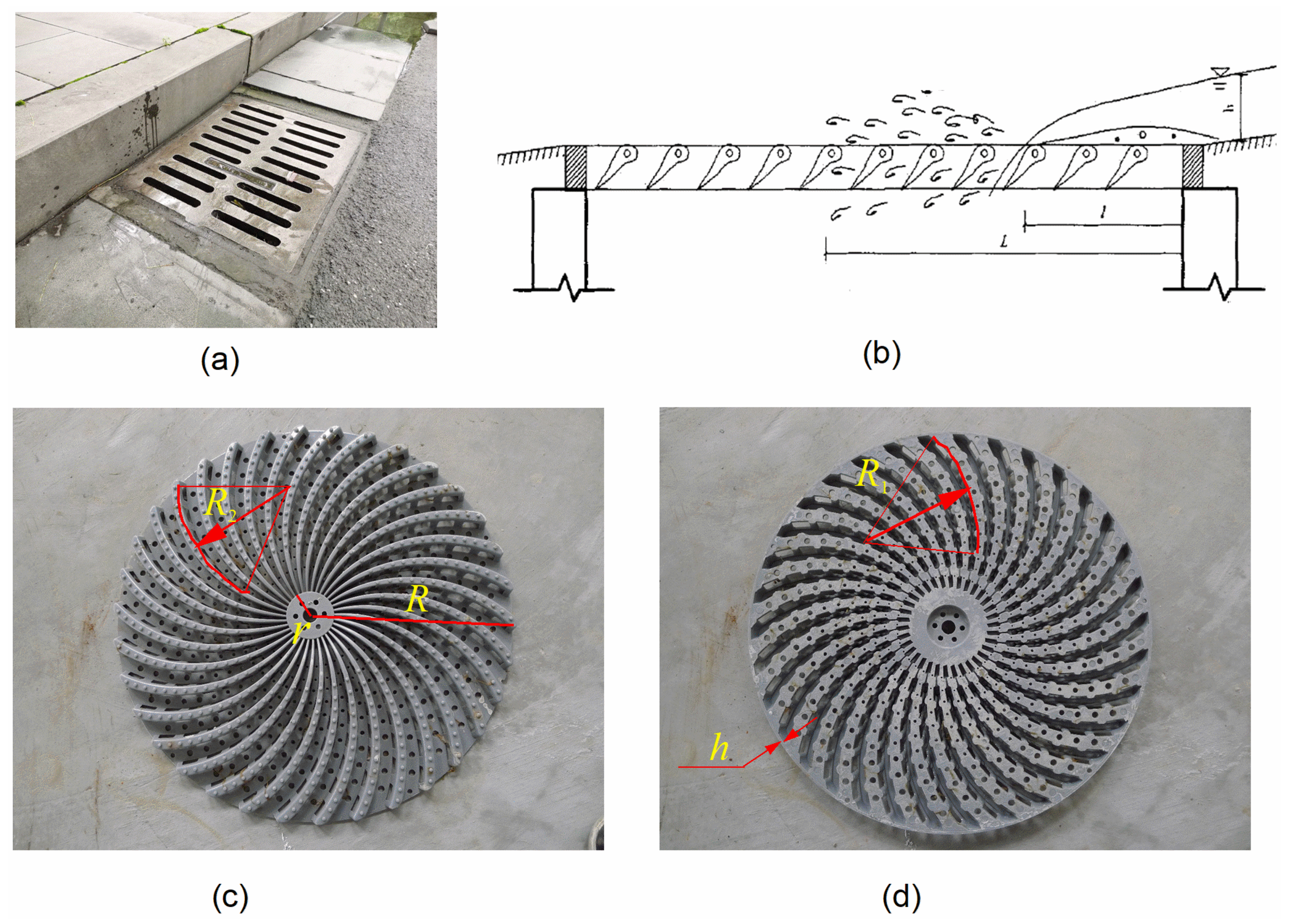
In urban drainage systems, manhole covers not only connect the surface runoff with urban drainage network, but also effectively filter floating objects and other impurities in rainwater [1,2]. Manhole covers can be mainly divided into three categories, including horizontal drainage, vertical drainage and mixed drainage [3]. Figure 1a presents a conventional manhole cover. This kind of manhole cover has many advantages, such as convenient installation and high pressure enduring capacity. However, due to its large orifice, it has limited function on intercepting ground debris, which easily causes blockage of drainage systems and greatly reduces the drainage capacity [4,5]. Carty et al. experimentally investigated the effect of the passage of debris sediments across sewer structures [6]. Their research identified primary hydrodynamic mechanisms that affect the structural integrity of drop shafts.
Urban flood caused by storm-water runoff has attracted the attention of many scholars due to its massive destruction. Crispino et al. worked on supercritical flow in junction manholes [7]. They described the hydraulic features of shock waves typically occurring in supercritical flows in junctions. Wang et al. investigated the flow behavior in a circular pipe of steep slope [8]. They were committed to improving the design and hydraulic performance of storm sewer-pipes by understanding the jump behavior and resultant flow choking in a circular pipe. In addition, manhole covers are also important research objects in the range of the urban drainage systems. Wang et al. found that manhole covers can be blown-up where the underlying sewer channels are pressurized and the choking flow causing the geyser established [9]. In this paper, we aim to reduce urban flood damage by improving the drainage capacity of a particular type of manhole cover.
Drainage capacity is a dominant design parameter of manhole cover. It was found that the drainage characteristics of manhole cover vary with the depth of water. Some researchers divided the discharge process through manhole cover into weir flow process and orifice outflow process when calculating the drainage capacity [3,10]. In order to obtain the curve of discharge versus the depth of water and systematically study the drainage capacity of manhole cover, physical tests of different sizes of conventional manhole covers were carried out [11,12,13]. In recent years, various styles of manhole covers [14,15], such as airfoil-shaped manhole covers [16], have been proposed. Airfoil-shaped manhole cover consists of many ribs which have streamline sectional shapes like airfoil as presented in Figure 1b. Meanwhile, designers optimized the tilt angle of rib sections to reduce water resistance and improve the drainage capacity of manhole cover. Airfoil-shaped manhole covers will be fully effective when used on continuous slop roads, while having limited performance when the direction of water collection is irregular.
Researchers usually chose conventional manhole covers [17] as the research object to study their drainage capacity [18,19,20]. The corresponding empirical formula and flow-depth curve were well studied [9,21]. The turbine-type manhole cover is a kind of new manhole cover, while there is no relative research about its hydraulic characteristic. Figure 1c,d presents the typical turbine-type manhole cover from different views. Compared with conventional manhole covers, the structure and discharge characteristics of turbine-type manhole covers are more complex. In this paper, the discharge capacity and flow field characteristics of the turbine-type manhole cover were studied through both numerical simulation and physical experiments. To better understand the features and design of turbine-type manhole covers, the effects of the depth of water above manhole covers and precipitation intensity on the discharge capacity of turbine-type manhole covers were analyzed in this paper. The research results provide references for practical applications of turbine-type manhole covers.
2. Description of Turbine-Type Manhole Cover
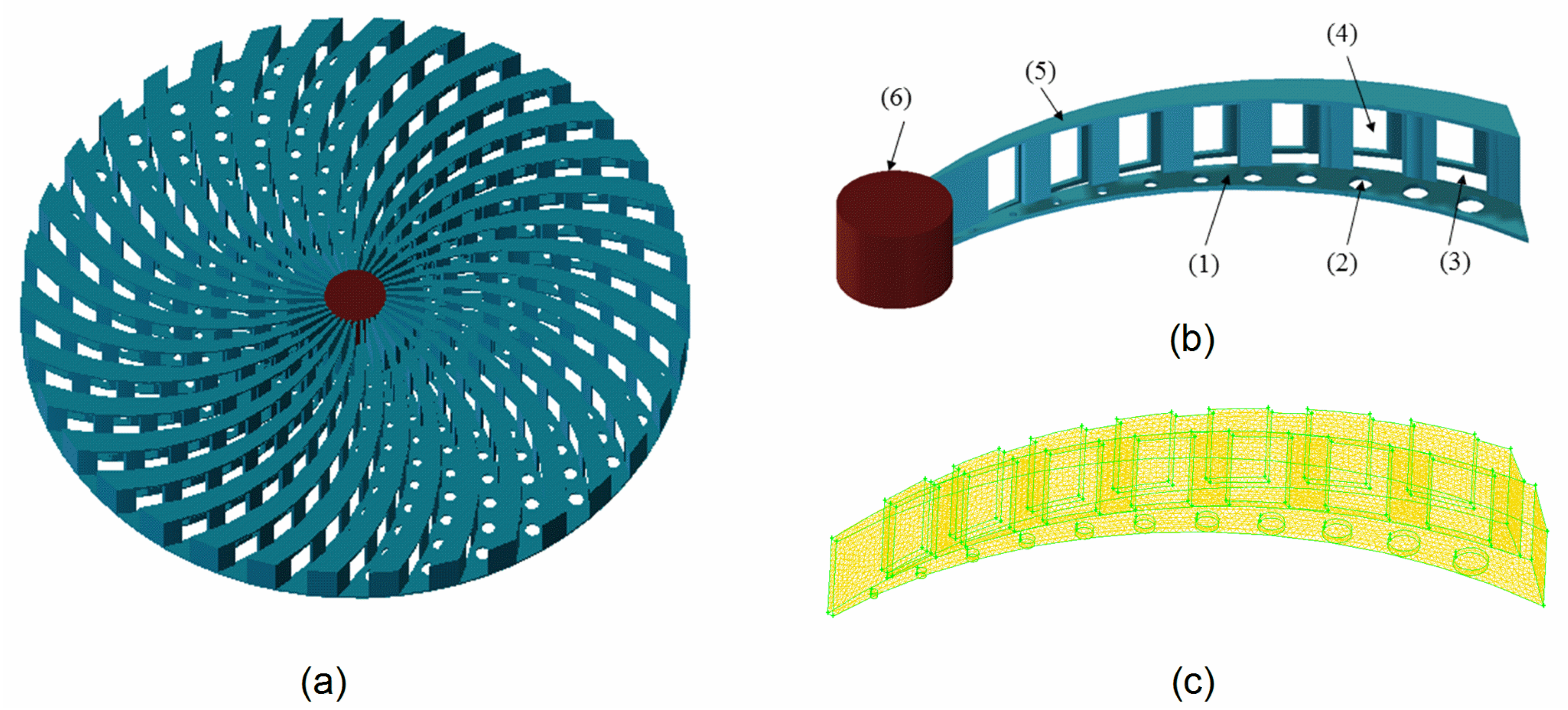
A three-dimensional model of turbine-type manhole cover was created as shown in Figure 2a. Figure 2b presents the detailed structure of the rib of turbine-type manhole cover. As shown in the figure, the main structure of turbine-type manhole cover consists of two parts: an arcuate panel and a drainage bridge. Arcuate panels are located at the bottom of the turbine-type manhole cover. There are several horizontal round holes of different sizes upon the central line of each arcuate panel. The opening of these horizontal round holes can increase the drainage area of turbine-type manhole cover. At the same time, they are utilized for discharging air into the rain water timely to avoid negative pressure. In addition to arcuate panels, there are gaps named arcuate sink at the bottom of turbine-type manhole cover. Arcuate sinks and arcuate panels are interlaced and have the same width. A drainage bridge is installed above each arcuate sink. The height of the drainage bridge is the same as the thickness of turbine-type manhole cover. Both sides of the drainage bridge have vertical openings. In the center of turbine-type manhole cover, arcuate panels and drainage bridges are fixed on the central cylinder axis. The dimensions of the turbine-type manhole cover used in this study are listed in Table 1.
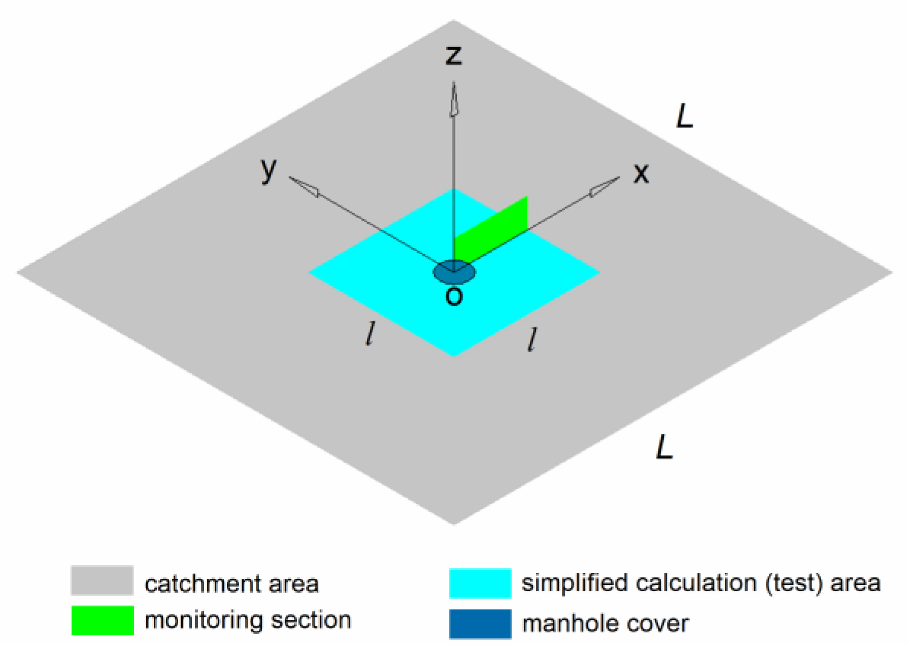
In the paper, manhole covers were considered to drain water in a square catchment area with side length L. Due to the large area of the actual catchment area, it is not convenient for numerical calculation and model test, we simplified it into a small square area with side length l. Figure 3 describes the catchment area and the simplified calculation (test) area. The simplified model follows the principle that all the rainfall received by the catchment area converges to the manhole cover, that is, the total precipitation q1 in the catchment area is equal to the water inflow q2 around the simplified calculation area. In addition, considering the surface runoff loss, the runoff loss coefficient φ was set as 0.9 according to the nature of the underlying surface. Then, Equation (1) is obtained.
3. Numerical Simulation
3.1. Modelling and Meshing
In numerical simulation, computational model consists of two parts: the simplified calculation (test) area and the turbine-type manhole cover. ICEM-CFD is used to generate hybrid meshes [22]. Considering the complicated structure of turbine-type manhole cover, 3D unstructured grids are used to mesh the computational area of turbine-type manhole cover. At the same time, the meshes of this computational area are refined. After verifying the grid independence and considering the computer performance, the number of the grid in the section of turbine-type manhole cover is determined to be about 150,000, while the number of the grid in the cuboid water catchment area is about 2.06 million. The grid division of one rib of turbine-type manhole cover is shown in Figure 2c.
3.2. Governing Equations
In this paper, the transient drainage process of the turbine-type manhole cover was simulated through numerical calculation. VOF model [23] and k-ε model [24] were adopted to simulate turbulence. The basic equations of the numerical model are composed of physical property equation, continuity equation, Reynolds average Navier–Stokes equation of mixed fluid, turbulent kinetic energy equation (k equation) and turbulent dissipation rate equation (ε equation) [25]. In VOF model, the volume fraction of phase i is denoted by αi, air and liquid phases are involved in the model, so the value of i is 1 or 2. The density equation of the mixture is
where ρ is the density of the mixture, ρ1 and ρ2 are the density of the first and second phases, respectively. In this case, continuity equation can be expressed as
where ui is the velocity of the mixture. The Reynolds average Navier–Stokes equation of mixed fluid is
where t is time, p is the pressure, g is the acceleration of gravity, μi is the coefficient of turbulence viscosity, which is defined as
where k is turbulent kinetic energy and ε is turbulent dissipation rate. Turbulent kinetic energy equation (k equation) is described as
Gk represents the turbulent kinetic energy resulting from laminar velocity gradients and is defined as
and turbulent dissipation rate equation (ε equation) is
where the values of constants Cμ, C1ε, C2ε, σk, σε are 0.09, 1.44, 1.92, 1.0, 1.3, respectively.
3.3. Boundary Conditions
The simplified calculation (test) area is surrounded by velocity inlet boundaries. The numerical model is established to study the conditions of heavy rainfall [9], mainly considering the conditions of precipitation intensity P of 1.5 mm/min, 3.0 mm/min, 4.5 mm/min, 6.0 mm/min, 7.5 mm/min, and 9.0 mm/min. To facilitate numerical calculation, the environment is simplified as follows: turbine-type manhole cover is applied to drain rain from the square, the distance L between two adjacent turbine-type manholes is 42 m. The value of runoff coefficient is related to the characteristics of underlying surface. According to the building water supply and drainage design code, when the ground surface is concrete and asphalt pavement, the runoff coefficient value is 0.9. So, the runoff coefficient φ of the square is 0.9. According to Equation (1), the relationship between the velocity of the inlet boundary in the model and the actual precipitation intensity P can be established by the following formula
where A is the total area of the cross section at velocity inlet boundaries.
After calculation, the corresponding relationships between actual precipitation intensity P and model boundary velocity v are listed in Table 2.
Some other boundary conditions are reported as follows: horizontal round holes in arcuate panels and vertical openings in drainage bridges are defined as pressure outlet and the initial pressure is atmospheric. The simplified calculation (test) area in the model is an open flume. The top of the flume is a pressure outlet and the initial pressure is atmospheric pressure as well. The bottom of the model flume and the main structure of turbine-type manhole cover are solid wall surface, assuming that they have the characteristics of heat insulation and no slip.
3.4. Computing Method
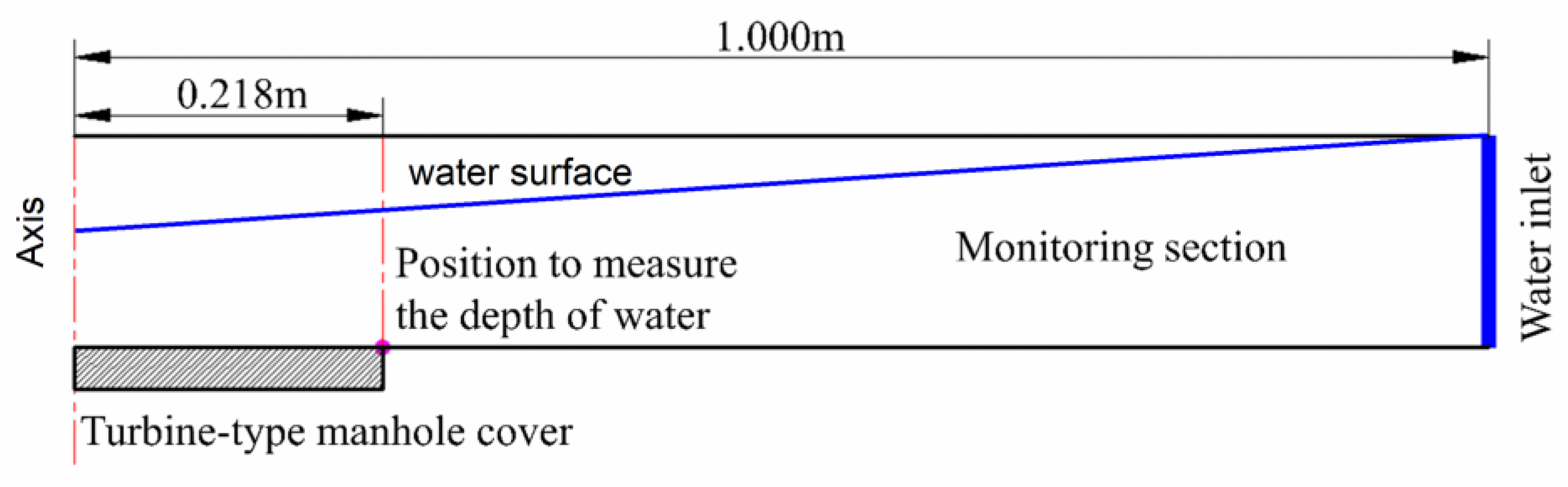
The finite volume method (FVM) is applied to discretize and integrate the governing equations [26]. In terms of discretization schemes, mixed format is employed in convective terms and diffusive terms, and second order central difference scheme is used in source term [27,28,29]. The time step is fixed at 0.01 s. During calculation, the maximum iteration of each time step is 200 steps and the target value of convergence residual is 0.001. PISO algorithm [30] is adopted to decouple the velocity field from the pressure field. Second order precision is selected as the difference precision between space and time. In order to observe the fluctuations of the water surface during the drainage process, the axial plane of the calculation model is set as the monitoring section. The position in the axial plane which is 0.218 m away from the central axis is selected as the location of water depth measurement. The depth measured at this place is named as the depth of water above manhole cover H in the paper. Monitoring section and the location of the depth measurement are presented in Figure 4. In addition, the monitoring section is marked with green in Figure 3.
4. Numerical Calculation Results and Analysis
4.1. Drainage Characteristics
A unit of the turbine-type manhole cover as shown in Figure 2b has been chosen to analyze the hydraulic characteristics when it works. In the process of discharge of turbine-type manhole, at time t, the volume of water in the arcuate sink with arcuate panel as its base is V and the depth of the water above manhole cover is H. Suppose there is a certain time t0, at which time the arcuate sink is just filled with water, the volume of water in the arcuate sink is V0, which is equal to the volume of the sink, and the depth of water above the manhole cover is H0. The volume fraction of the water in the sink can be described by the dimensionless number m. The expression of m is written as
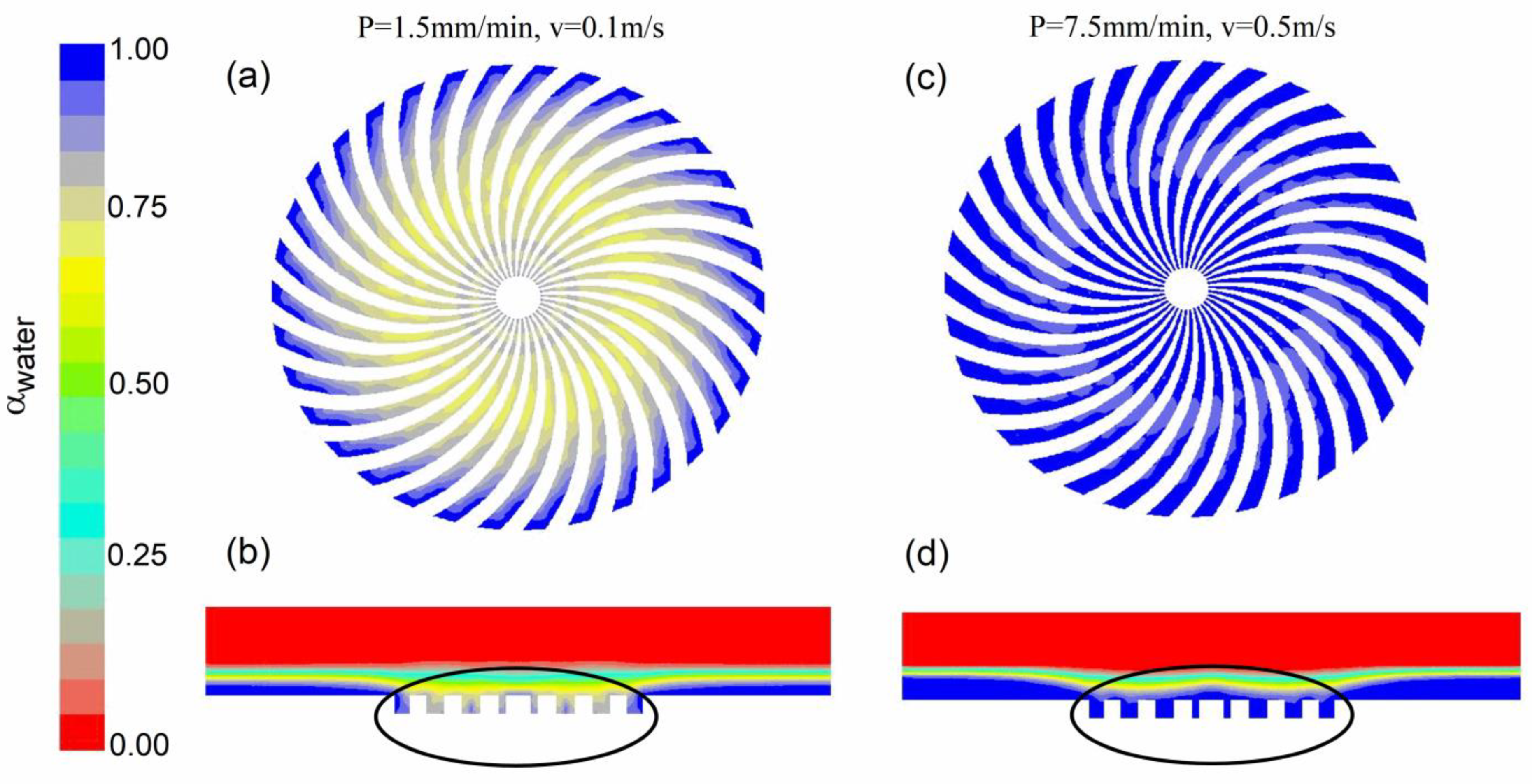
When the arcuate sink is not fully filled with water, m is less than 1. H is less than or equal to H0. Meanwhile, the vertical openings on either side of the drainage bridge are not completely flooded. In this case, the water that converges from the ground falls in a parabolic pattern from the top of the outside of turbine-type manhole cover into the arcuate sink. Restricted by the wall of arcuate sink, due to the fluid inertia, water flows along arcuate panel to the middle position (the position of Z axis in Figure 3) of turbine-type manhole cover. A small portion of them flows out through horizontal round holes in the arcuate panel. Most of the water is drained out through vertical openings on both sides of the drainage bridge. In addition, there is a little water flowing along the arcuate panel to the outside of turbine-type manhole cover, forming local backflow. The discharge process like this, characterized by m less than 1 and outlets not completely submerged, is defined as free flow regime in the paper. Contours of phases are created to visualize the distribution of water. In the contours, different colors are selected to represent the distribution of different phases. For example, one place is full of water, the volume fraction of water at this location is 1, then this position is marked with blue to indicate the phase at this place is water. If some places are marked with red, it means that the volume fraction of water is 0 and there is no water at these positions. Figure 5a,b describe the contours of phases at the condition of free flow regime. Figure 5a indicates the fluid distribution at the top of turbine-type manhole cover and Figure 5b represents the fluid distribution on the axial plane of the whole flow field. It is found that the middle area is light yellow and the surrounding is blue in Figure 5a. In Figure 5b, the position circled by a black circle is the longitudinal section of turbine-type manhole cover. Corresponding to Figure 5a, the middle part of the longitudinal profile is light yellow, while the two sides are blue. From the figure, it is obtained that at the moment, turbine-type manhole cover is not fully filled with water. Water is mainly distributed in the peripheral area, and there still remains a lot of air in the middle of turbine-type manhole cover.
When the whole arcuate sink is filled with water and there is a certain depth of water gathered above the arcuate panel, m is equal to 1. H is greater than or equal to H0. Meanwhile, all outlets are completely flooded. In this condition, blocked by the wall of arcuate sink, the horizontal flow velocity of water has little influence on the drainage of turbine-type manhole cover. The depth of water and pressure in the arcuate sink approximately satisfy the characteristics of static pressure distribution. The discharge process like this, characterized by m greater than or equal to 1 and outlets completely submerged, is defined as the submerged flow regime in the paper. Figure 5c,d present the contours of phases at the condition of submerged flow regime. The area at the top of the turbine-type manhole cover in Figure 4 and the section inside the black circle in Figure 5d are all blue. These indicate that the turbine-type manhole cover is filled with water at this moment. The characteristics of the free flow regime and the submerged flow regime are described in Formula (12).
4.2. Analysis of Drainage Process
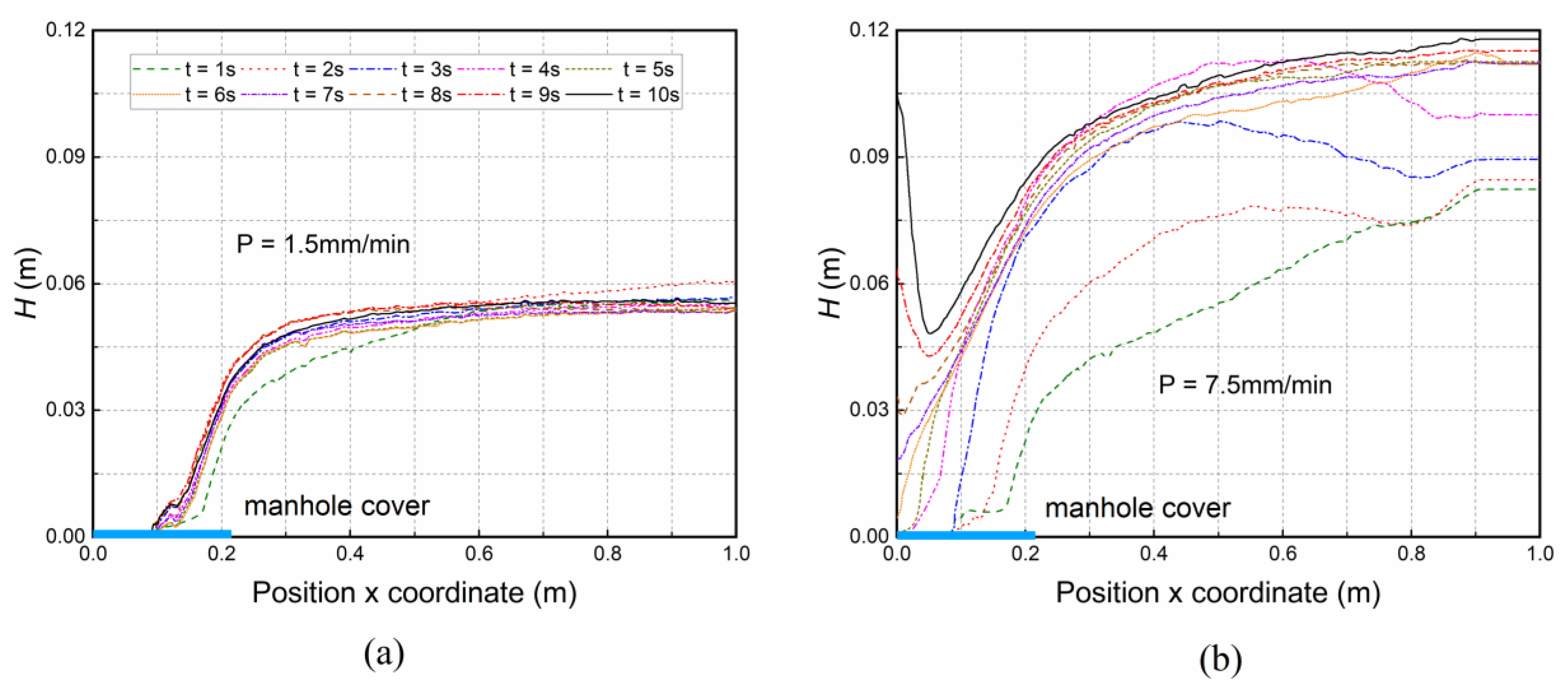
The process of rainwater flowing into urban drainage system through turbine-type manhole cover was simulated by numerical calculation. Analyzing the numerical simulation results, the fluctuations of water surface under each condition are obtained. Through comparison, it is found that the discharge characteristic of turbine-type manhole cover is typical when the precipitation intensity P is 1.5 mm/min and 7.5 mm/min, respectively. Considering the symmetry of the flow field, the variation curves of the water surface under these two conditions are exhibited in Figure 6. The horizontal axis represents the X-axis, and the position where x equals 0 is the origin of the coordinates. The coordinate system can be referred to in Figure 3.
Figure 6a indicates the variation of water surface when P is 1.5 mm/min. It is observed from the figure that arcuate sinks are not fully filled with water, dimensionless number m is always less than 1, and the whole process is maintained as free flow regime all along. At the beginning of drainage, the water surface rises rapidly and H increases at a fast speed. The volume of water in the arcuate sink increases gradually while it cannot fully fill the arcuate sink all the time. This period is characterized by gradually filling the arcuate sink with water. The free flow regime is in an unstable state at this moment, which is called unstable discharge in this paper. After a period of time, water level rises to a certain height, fluctuating up and down within a small range, and gradually stabilizes. The volume of water in the arcuate sink is no longer increasing. The discharge of turbine-type manhole cover is equal to the inflow at this moment. Free flow regime with these characteristics is in a stable state, which is named as stable free flow regime.
Figure 6b presents the variation of water surface when P is 7.5 mm/min. In the initial stage of discharge (corresponding to the period from 0 s to 4 s in Figure 6b, arcuate sinks are not totally filled with water, and H is relatively low, so it is in the condition of free flow regime. Subsequently, water fills the arcuate sinks step by step and forms backwater above manhole cover. H continues to increase, and the state of drainage converts from free flow regime to submerged flow regime after 4 s in Figure 6b. Similar to free flow regime, submerged flow regime can be divided into unstable submerged flow regime and stable submerged flow regime.
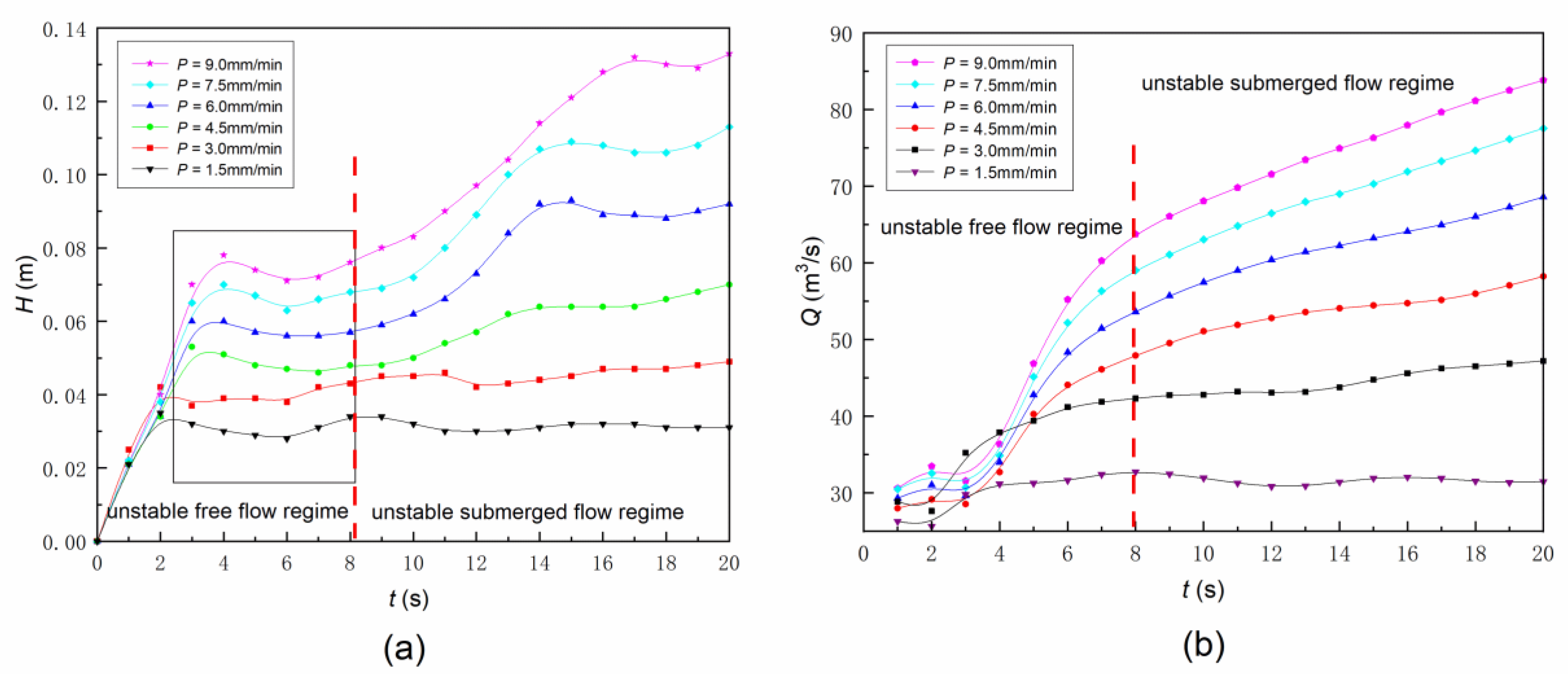
From the numerical calculation results of drainage under different working conditions, the depth of water above manhole cover H and the corresponding discharge Q at each moment are measured. The relationship between H and time t is represented by H-t curves as shown in Figure 7a. The variation of Q changing with time t is exhibited by Q-t curves as shown in Figure 7b. The following inferences are obtained through the analysis of Figure 6 and Figure 7, combined with the characteristics of the drainage of turbine-type manhole cover. In the case of heavy rainfall, the drainage process of turbine-type manhole cover includes three stages: unstable free flow regime, unstable submerged flow regime and stable submerged regime. Figure 7 is divided according to the flow state. In the time period from 0 to 8 s, it is unstable free discharge. In the time period from 8 to 20 s, it is unstable submerged discharge. Due to a short period of time, the stable submerged discharge has not been reached. The existence of the stable submerged discharge is obtained by theoretical analysis. The growth rate of discharge in unstable free flow regime is greater than that of unstable submerged flow regime. The reason is the main factor affecting the drainage in unstable free flow regime is the actual drainage area, while the decisive factor of discharge in unstable submerged flow regime is H. The actual drainage area increases rapidly with the increased volume of water in arcuate sinks. Due to the large area of flow field, H varies relatively slowly.
4.3. Analysis of Influence Factors
4.3.1. Influence of Precipitation Intensity on Drainage
It is obviously observed from the area marked with black box in Figure 7a that there exists a particular period in the later stage of unstable free flow regime, during which H has little variation. Ignoring the influence of the fluctuations of water surface, H is approximately constant. In addition, this situation will continue until the condition of drainage converts to unstable submerged flow regime. Therefore, it can be inferred that at this particular period, H is always equal to H0 which is the depth defined when arcuate sinks are just fully filled with water. Hence, H0 is adopted in the following part of the paper to represent the depth of water in this particular stage.
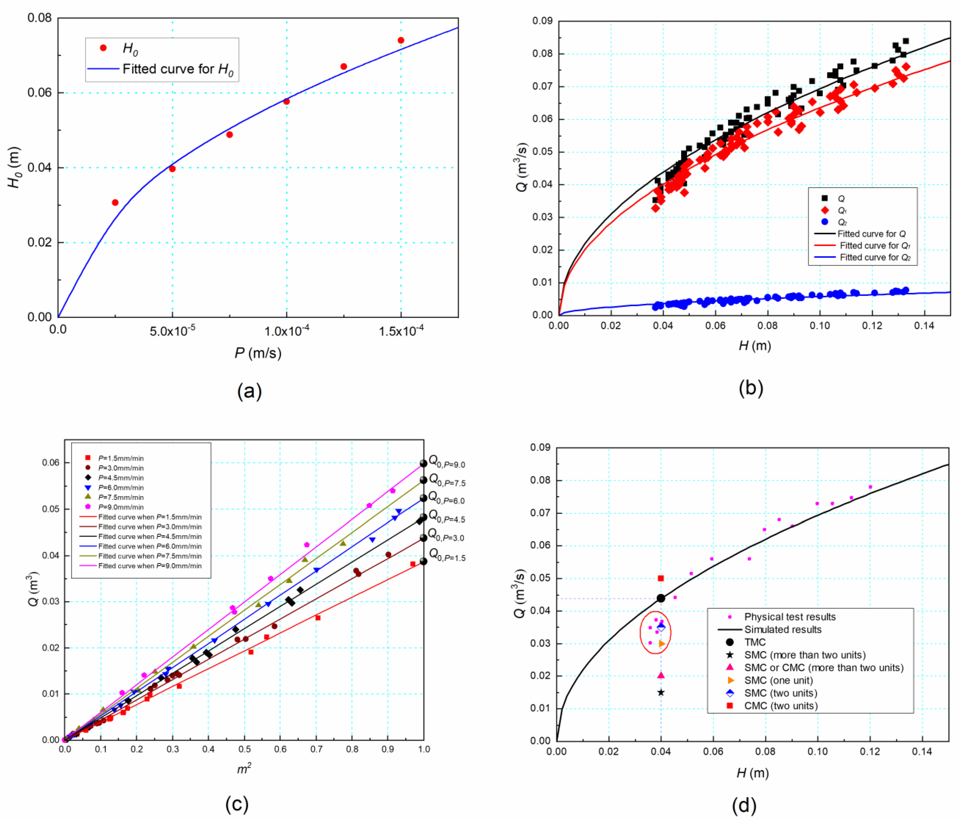
H0 is obtained by averaging the calculated value of H in this particular period under different operation conditions. Comparing the curves in the black box in Figure 7a, it can be found that H0 varies with the precipitation intensity P. H0 and corresponding P are plotted in Figure 8a, the abscissa representing precipitation intensity and the ordinate representing the depth of water. All units are converted to international units. According to the fitted curve of scattered points, H0 is linearly correlated with the square root of P. The relationship between H0 and P can be expressed as follows.
In Formula (13), K is the characteristic coefficients of turbine-type manhole cover. The value of K is 5.864, being calculated from the numerical results.
The explanation for the existence of this particular period is the special structure of turbine-type manhole cover. Hindered by the arcuate panel at the bottom of the sink, water gathers in the arcuate sink, presenting the process of filling the sink. Before the sink is fully filled with water, the outside water will be continuously replenished, so as to keep the depth of water above manhole cover remaining, which is always equal to H0. As can be seen from Figure 8a, when the structure of turbine-type manhole cover is fixed, precipitation intensity P determines H0.
4.3.2. Influence of the Depth of Water on Drainage
According to the analysis of flow process in Section 4.2, H and total discharge Q increase synchronously in the period of unstable submerged flow regime. Total discharge Q can be divided into discharge through vertical openings Q1 and the discharge through horizontal round holes Q2. The main factors affecting total discharge Q are the area of vertical openings A1, the area of horizontal round holes A2, and the depth of water above manhole cover H. The calculation formulas of discharge flow Q1, Q2 and Q can be acquired as follows by adopting Rayleigh method (a method of dimensional analysis) and referring to the calculation formulas of orifice flow. In Formulas (14) and (15), β1 and β2 are dimensionless numbers representing the discharge coefficients of vertical openings and horizontal round holes, respectively.
The numerical results of H and the corresponding discharge Q1, Q2, Q during the period of unstable submerged flow regime are plotted into a scatter diagram, as shown in Figure 8b. The Least Square Method [31,32] is employed to fit the scatter points in the figure, and the expressions of fitting curves are as
where the values of k1, k2 and k are 0.201, 0.018 and 0.219 independently. The area of vertical openings A1 and horizontal round holes A2 can be received from the model of turbine-type manhole cover to be 0.125 m2 and 0.060 m2. So it is calculated that the values of β1 and β2 are 0.363 and 0.068. It is observed that the values of β1 and β2 are significantly smaller than the literature values. This is due to the existence of a large water surface slope above the manhole cover (as shown in Figure 9. The closer to the axis of manhole cover (the Z axis), the smaller the actual water depth at the orifice. According to the definition of the depth H in the paper, H refers to the depth of water at the outer edge of the manhole cover. Hence, H is larger than the actual water depth at each orifice, the comprehensive discharge coefficient obtained by using H is smaller than the value in the literature. In addition, the existence of the vertical openings affects the discharge coefficient of the horizontal holes. The area of the vertical openings is about twice that of the horizontal holes. The flow resistance of the vertical openings is far less than that of the horizontal holes. In this way, water will preferentially pass through the vertical openings, thus further reducing the discharge coefficient of the horizontal holes.
η1 and η2 are dimensionless numbers introduced to describe the functions of vertical openings and horizontal round holes in the discharge process of turbine-type manhole cover. The expressions for η1 and η2 are as Formula (17).
The value of η1 is calculated to be 91.8% and the value of η2 is 8.2%. The value of η1 is much larger than that of η2. This indicates in terms of the function orientation of the turbine-type manhole cover, vertical openings play the major role in water drainage due to its great drainage capacity. Different from vertical openings, horizontal round holes have smaller drainage capacity because of their small flow areas and mainly have the function of exhaust.
It can be concluded from the data analysis above that H determines the discharge flow Q in unstable submerged flow regime. Additionally, the square root of H has linearly relationships with Q1, Q2 and Q.
4.3.3. Research on the Correlation between m and Q
It is mentioned above that m is a dimensionless number representing the volume fraction of water in the arcuate sink. The value of m varies in the range of 0.0~1.0 in free flow regime stage, while remains constant at 1.0 in submerged flow regime stage. Through the regression analysis of m and Q in free flow regime, it is found that m2 and Q are linearly correlated, as shown in Figure 8c. We can also calculate that when m is 1.0, Q is exactly equal to Q0 through this linear relationship. This result is the same as that calculated by Formula (14) when H is equal to H0 in unstable submerged stage, which accords with the continuity characteristics of flow. The correlation between m and Q can be expressed as
where Q0 is related to precipitation intensity P and can be calculated from Formula (19).
5. Validation
5.1. Physical Model Design
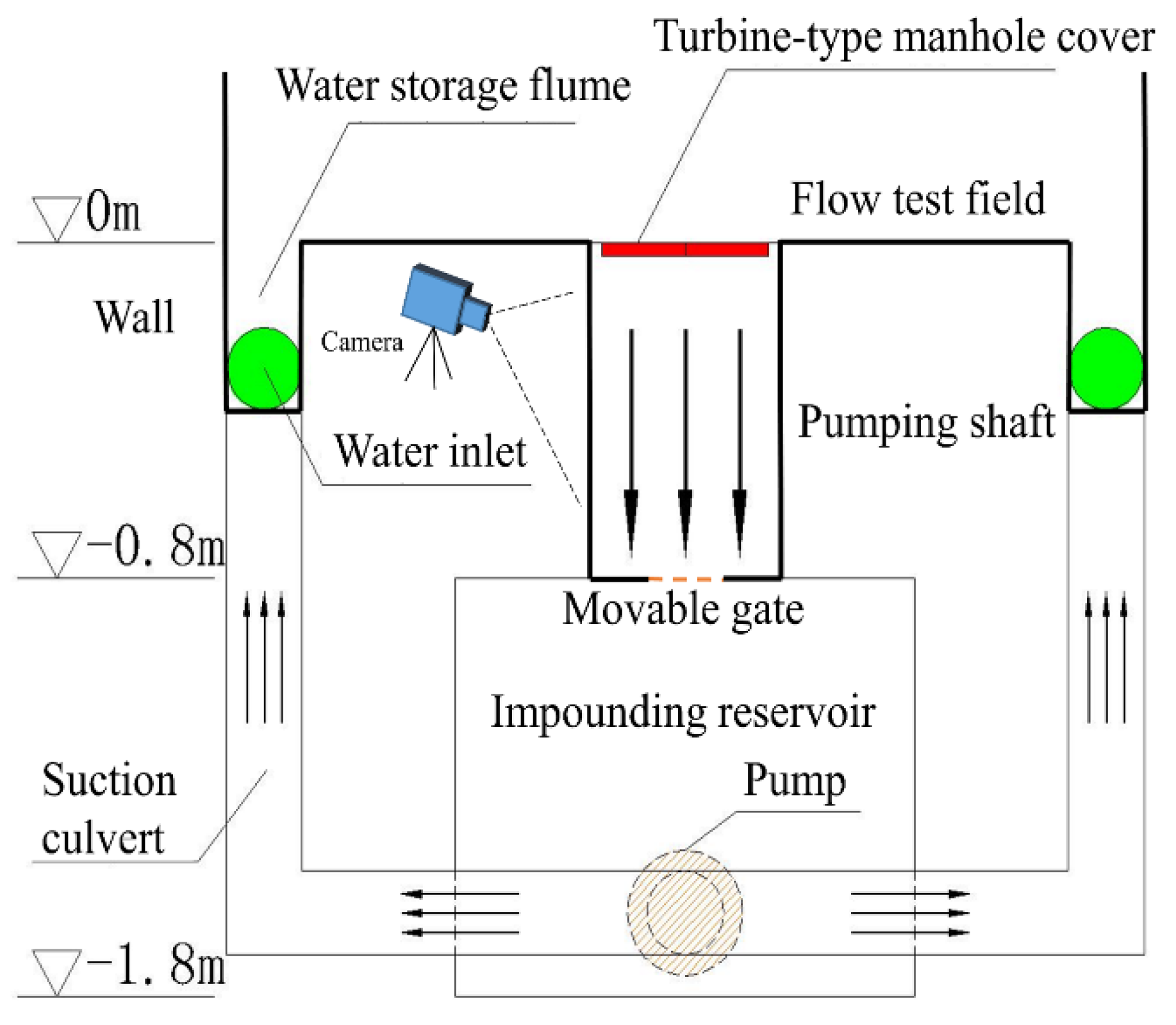
Physical experiment is an effective method to validate the numerical results. In order to validate the numerical model, we conducted the drainage experiment of the turbine-type manhole cover in the Civil and Hydraulic Engineering Laboratory of Zhejiang University. In this study, the physical model is a 1:1 normal-scale model, and the layout of the whole experimental platform is shown in Figure 10. The dimensions of the turbine-type manhole cover and the test platform refer to Table 1. The material of the turbine-type manhole cover is resin. This platform consists of the following parts: water inlets on both sides, water storage flume, turbine-type manhole cover, pumping shaft, movable gate, camera, impounding reservoir, pump and suction culvert. Figure 1c,d demonstrate the actual turbine-type manhole cover from different views.
In the experiment, the inlet flow velocity is controlled by adjusting the pump. In addition, several flow rate meters are set at the boundary of the flow field to obtain the instantaneous velocity, so that the inlet velocity is ensured to satisfy the test requirements. A needle water level gauge is applied to observe the depth of water above the manhole cover. Its precise position is presented in Figure 4. The accuracy of the needle water level gauge is 0.1 mm. Next to the pumping shaft, a camera is set up to monitor the fluctuations of water surface in the pumping shaft. When the pump works, the movable gate will be closed to accumulate the water depth. The variation of water volume can be extracted from videos taken by the camera in the pumping shaft.
5.2. Physical Test Results
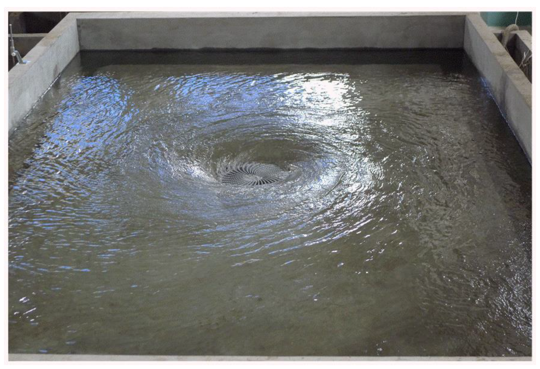
Figure 9 describes the physical model. In the process of model experiment, it is observed that during the discharge process of turbine-type manhole cover, free flow regime has a very short duration and the relevant physical quantities, especially volume fraction m, are difficult to measure. Therefore, the depth of water and the corresponding discharge flow measured by the physical model test are mostly in the stage of unstable submerged flow regime. Values of H and Q are listed in Table 3.
The measured H and Q in Table 3 are plotted as a scatter diagram in Figure 8d. Meanwhile, the curve corresponding to Formula (15) in Section 4.3 is plotted in the figure for comparison. It is observed that most of the points representing experimentally measured H and Q are distributed near the fitting curve of H-Q obtained by numerical calculation. While several points marked with a red circle in Figure 8d deviate from the fitting curve by some distance. Through calculation and comparison, it can be found that the physical quantities (H and Q) represented by these deviating points conform to the characteristics of free flow regime. This indicates that when these deviating points were measured, the discharge stage of turbine-type manhole cover did not reach submerged flow regime and still belonged to free flow regime. Therefore, these deviating points do not pertain to the research object of this section, and they can be omitted. It can be concluded from Figure 8d that the numerical simulation results are in good agreement with the physical test ones. Hence, the results of numerical calculation in the paper are accurate and reliable.
5.3. Comparison with Normal Manhole Covers
In the design of manhole covers, engineers usually pay more attention to the drainage capacity of manhole covers [3]. Design drainage capacity is a regular reference index, which is defined as the discharge of various types of manhole cover when the depth of water above manhole cover is 40 mm under design operation condition. According to Formula (19), design drainage capacity of turbine-type manhole cover is 43.8 L/s, which is marked with a black point in Figure 8d. Design drainage capacity of conventional manhole covers can be consulted from the design handbook for manhole covers, as shown in Table 4 below. It is revealed that design drainage capacity of turbine-type manhole cover is greatly improved compared with combined manhole cover, and is equivalent to that of the combined manhole cover having more than two units. Therefore, it is concluded that turbine-type manhole cover has a great advantage in drainage capacity.
6. Conclusions
The hydraulic characteristics and influence factors of turbine-type manhole cover were analyzed through numerical simulations. The effects of precipitation intensity on drainage were investigated, the relationship between the depth of water above manhole cover and discharge was analyzed, and finally the calculation formula for the discharge of turbine-type manhole cover was obtained. In addition, a physical experiment was carried out to study the hydraulic characteristics of turbine-type manhole cover, and the corresponding relationships between the depth and discharge were obtained through model test. The numerical simulation results agree well with the measured data of physical model test, which indicates the results from numerical simulation are accurate and reliable. Compared with conventional manhole covers, the discharge capacity of turbine-type manhole cover is improved greatly due to its special form of structural design. A peculiar period exists in the later stage of free flow regime of turbine-type manhole cover, which has the characteristic that the discharge increases while the depth of water remains constant at H0 which is determined by precipitation intensity and linearly correlated with the square root of it. The calculation of the discharge of turbine-type manhole cover needs to be divided into two situations: free flow regime and submerged flow regime. In the stage of free flow regime, discharge is influenced by m and linearly correlated with m2. In the stage of submerged flow regime, discharge is determined by the depth and linearly correlated with the square root of the depth. The characteristics and calculation formula of discharge flow of turbine-type manhole cover obtained in this paper will provide reference for the design and selection of turbine-type manhole cover.
Author Contributions
W.W. contributed to the conception of the study; L.F. and H.Z. performed the experiment; W.W., L.F. and B.Z. contributed significantly to analysis and manuscript preparation; L.F. performed the data analyses and wrote the manuscript; H.Z. and Z.B. helped perform the analysis with constructive discussions. All authors have read and agreed to the published version of the manuscript.
Funding
This work was supported by National Key R&D Program of China (Grant No. 2018YFC0407203) and the National Natural Science Foundation of China (Grant Nos. 52079122, 51779216).
Institutional Review Board Statement
Not applicable.
Informed Consent Statement
Not applicable.
Data Availability Statement
The data and materials that support the findings of this research are available from the corresponding author upon reasonable request.
Acknowledgments
This research is supported by Civil and Hydraulic Engineering Laboratory of Zhejiang University.
Conflicts of Interest
The authors declare no conflict of interest.
Abbreviations
| α1, αwater; | Volume fraction of water |
| α2, αair | Volume fraction of air; |
| ρ | Density of the mixture; |
| ρ1 | Density of water and water; |
| ρ2 | Density of water and air; |
| u | Velocity; |
| t | Time; |
| p | Pressure; |
| g | Acceleration of gravity; |
| μt | Coefficient of turbulence viscosity; |
| k | Turbulent kinetic energy; |
| ε | Turbulent dissipation rate; |
| P | Precipitation intensity; |
| L | Distance between adjacent turbine-type manholes; |
| φ | Runoff coefficient; |
| A | Total area of the cross section at velocity inlet boundaries; |
| V | Volume of water in the arcuate sink; |
| V0 | Volume of the sink; |
| m | Volume fraction of the water in the sink |
| H | Depth of water above manhole cover; |
| Q | Discharge; |
| K | Characteristic coefficients of turbine-type manhole cover; |
| Q1 | Discharge through vertical openings; |
| Q2 | Discharge through horizontal round holes; |
| A1 | Area of vertical openings; |
| A2 | Area of horizontal round holes; |
| β1 | Dimensionless number representing the discharge coefficient of vertical openings; |
| β2 | Dimensionless number representing the discharge coefficient of horizontal round holes; |
| η1 | Dimensionless number describing the function of vertical openings; |
| η2 | Dimensionless number describing the function of horizontal round holes; |
| TMC | Turbine-type manhole cover; |
| SMC | Single conventional manhole cover; |
| CMC | Combined conventional manhole cover. |
References
- Bach, P.M.; Rauch, W.; Mikkelsen, P.S.; McCarthy, D.T.; Deletic, A. A critical review of integrated urban water modelling—Urban drainage and beyond. Environ. Model. Softw. 2014, 54, 88–107. [Google Scholar] [CrossRef]
- Zhou, Q. A Review of Sustainable Urban Drainage Systems Considering the Climate Change and Urbanization Impacts. Water 2014, 6, 976–992. [Google Scholar] [CrossRef]
- Cullen, M.; Sherrie, M.P.; Warner, K.D.; Webb, R.J. Urban Drainage Design Manual; University Press of the Pacific: Honolulu, HI, USA, 1983. [Google Scholar]
- Butler, D.; Parkinson, J. Towards sustainable urban drainage. Water Sci. Technol. 1997, 35, 53–63. [Google Scholar] [CrossRef]
- Xia, J.; Zhang, Y.Y.; Xiong, L.H.; He, S.; Wang, L.F.; Yu, Z.B. Opportunities and Challenges of the Sponge City Construction Related to Urban Water Issues in China. Sci. China Earth Sci. 2017, 60, 652–658. [Google Scholar] [CrossRef]
- Carty, A.; Neill, C.O.; Nash, S.; Clifford, E.; Mulligan, S. Hydrodynamic modelling approaches to assess mechanisms affecting the structural performance and maintenance of vortex drops shaft structures. J. Struct. Integr. Maint. 2019, 4, 162–178. [Google Scholar] [CrossRef]
- Crispino, G.; Pfister, M.; Gisonni, C. Supercritical flow in junction manholes under invert- and obvert-aligned set-ups. J. Hydraul. Res. 2019, 57, 534–546. [Google Scholar] [CrossRef]
- Wang, C.; Li, S.S. Hydraulic Jump and Resultant Flow Choking in a Circular Sewer Pipe of Steep Slope. Water 2018, 10, 1674. [Google Scholar] [CrossRef] [Green Version]
- Wang, J.; Vasconcelos, J.G. Investigation of Manhole Cover Displacement during Rapid Filling of Stormwater Systems. J. Hydraul. Eng. 2020, 146, 04020022. [Google Scholar] [CrossRef]
- Fletcher, T.D.; Shuster, W.; Hunt, W.F.; Ashley, R.; Butler, D.; Arthur, S.; Trowsdale, S.; Barraud, S.; Semadeni-Davies, A.; Bertrand-Krajewski, J.-L.; et al. SUDS, LID, BMPs, WSUD and more—The evolution and application of terminology surrounding urban drainage. Urban Water J. 2015, 12, 525–542. [Google Scholar] [CrossRef]
- De Nardis, J.; Bernard, D.; Doyon, B. Hydrodynamic Diffusion in Integrable Systems. Phys. Rev. Lett. 2018, 121, 160603. [Google Scholar] [CrossRef] [Green Version]
- Del Giudice, G.; Gisonni, C.; Hager, W.H. Supercritical Flow in Bend Manhole. J. Irrig. Drain. Eng. 2000, 126, 48–56. [Google Scholar] [CrossRef]
- Itu, C.; Cerbu, C.; Galatanu, T.F. Modeling and Testing of the Sandwich Composite Manhole Cover Designed for Pedestrian Networks. Materials 2019, 12, 1114. [Google Scholar] [CrossRef] [PubMed] [Green Version]
- Liu, X.; Zhang, Q.; Yuan, X.; Li, J.; Wu, G.; Wu, M. Composite-Type Manhole Cover, Has Manhole Cover Connecting Pipe Flange Welded with Manhole Cover by Bolt, Flange Cover Connected with Manhole Cover Connecting Pipe Flange, and Feedstock Connecting Pipe Flange Welded with Flange Cover. China Patent CN205331691-U, 22 June 2016. [Google Scholar]
- Zhang, J. Manhole Cover, Has Well Cover Pedestal Whose Outer Side Is Fixed with Well Cover Pedestal Fixing Slot, and Cover Main Body Fixed with Water Leakage Hole, Where Well Cover Fixing Groove Is Fixed with Annular Well Cover Fixing Convex Part. China Patent CN204298938-U, 29 April 2015. [Google Scholar]
- Wu, P. Study on Hydrodynamic Characteristics and Discharge Capacitles of Airfoil-Shaped Gutter Grates. Master’s Thesis, Southwest Jiaotong University, Chengdu, China, 2015; p. 5. (In Chinese). [Google Scholar]
- Chen, A.S.; Leandro, J.; Djordjević, S. Modelling sewer discharge via displacement of manhole covers during flood events using 1D/2D SIPSON/P-DWave dual drainage simulations. Urban Water J. 2015, 13, 830–840. [Google Scholar] [CrossRef] [Green Version]
- Miller, D.J.; Kim, H.; Kjeldsen, T.R.; Packman, J.; Grebby, S.; Dearden, R. Assessing the Impact of Urbanization on Storm Runoff in a Pen-Urban Catchment Using Historical Change in Impervious Cover. J. Hydrol. 2014, 515, 59–70. [Google Scholar] [CrossRef] [Green Version]
- Martin, C.; Ruperd, Y.; Legret, M. Urban Stormwater Drainage Management: The Development of a Multicriteria Deci sion Aid Approach for Best Management Practices. Eur. J. Oper. Res. 2007, 181, 338–349. [Google Scholar] [CrossRef]
- Mustaffa, Z.; Rajaratnam, N.; Zhu, D.Z. An experimental study of flow into orifices and grating inlets on streets. Can. J. Civ. Eng. 2006, 33, 837–845. [Google Scholar] [CrossRef]
- Zhang, Z.; Zhao, Z.; Li, M.; Yang, P. Comparison of Drainage Capacity of Drainage Systems with Constant Flow and Instantaneous Flow. China Water Wastewater 2015, 31, 146–149. [Google Scholar]
- Ahuja, V.; Hosangadi, A.; Arunajatesan, S. Simulations of Cavitating Flows Using Hybrid Unstructured Meshes. J. Fluids Eng. 2001, 123, 331–340. [Google Scholar] [CrossRef]
- Hirt, C.; Nichols, B. Volume of fluid (VOF) method for the dynamics of free boundaries. J. Comput. Phys. 1981, 39, 201–225. [Google Scholar] [CrossRef]
- Chen, Q. Comparison of Different K-Epsilon Models for Indoor Air-Flow Computations. Numer. Heat Transf. Part B Fundam. 1995, 28, 353–369. [Google Scholar] [CrossRef]
- Menter, F.R. Two-equation eddy-viscosity turbulence models for engineering applications. AIAA J. 1994, 32, 1598–1605. [Google Scholar] [CrossRef] [Green Version]
- Beam, R.M.; Warming, R. An implicit finite-difference algorithm for hyperbolic systems in conservation-law form. J. Comput. Phys. 1976, 22, 87–110. [Google Scholar] [CrossRef]
- Leonard, B. A stable and accurate convective modelling procedure based on quadratic upstream interpolation. Comput. Methods Appl. Mech. Eng. 1979, 19, 59–98. [Google Scholar] [CrossRef]
- Shyy, W.; Thakur, S.; Wright, J. 2nd-Order Upwind and Central Difference-Schemes for Recirculating Flow Computa tion. AIAA J. 1992, 30, 923–932. [Google Scholar] [CrossRef]
- Wang, L.; Zhao, Y. Second-Order Approximation Function Method for Precision Estimation of Total Least Squares. J. Surv. Eng. 2019, 145, 04018011. [Google Scholar] [CrossRef]
- Jang, S.D.; Jetli, R.; Acharya, S. Comparison of the Piso, Simpler, and Simplec Algorithms for the Treatment of the Pressure Velocity Coupling in Steady Flow Problems. Numer. Heat Transf. 1986, 10, 209–228. [Google Scholar] [CrossRef]
- Cox, G.J.; Matuschak, M.C. An Abbreviation of the Method of Least Squares. J. Phys. Chem. 1941, 45, 362–369. [Google Scholar] [CrossRef]
- Hu, H.; You, X.; Xu, K. Universal Least Squares Method of a Linear Model. Sci. Surv. Mapp. 2008, 33, 101–832. [Google Scholar]
- Yao, Z. Handbook of Highway Drainage Design; China Communications Press: Beijing, China, 2002. (In Chinese) [Google Scholar]
Figure 1.
Manhole cover: (a) Conventional manhole cover; (b) Airfoil-shaped manhole cover; (c) Turbine-type manhole cover (Front view); (d) Turbine-type manhole cover (Back view).
Figure 1.
Manhole cover: (a) Conventional manhole cover; (b) Airfoil-shaped manhole cover; (c) Turbine-type manhole cover (Front view); (d) Turbine-type manhole cover (Back view).

Figure 2.
The numerical model of turbine-type manhole cover: (a) Three dimensional model of a turbine-type manhole cover; (b) Details of the one unit of turbine-type manhole cover, where numbers 1–6 represent arcuate panel, horizontal round holes, arcuate sink, vertical openings, drainage bridge and cylinder, respectively; (c) Grid divisions of flowing area of one unit of turbine-type manhole cover.

Figure 3.
Test layout and coordinate system setting.

Figure 4.
Monitoring section.

Figure 5.
Typical contours of fluid field at some point: (a) Contour of fluid field distribution at the top of turbine-type manhole cover at the condition of free flow regime; (b) Contour of fluid field distribution on the axial plane of the whole flow field at the condition of free flow regime; (c) Contour of fluid field distribution at the top of turbine-type manhole cover at the condition of submerged flow regime; (d) Contour of fluid field distribution on the axial plane of the whole flow field at the condition of submerged flow regime.

Figure 6.
Drainage process of turbine-type manhole cover: (a) variation of water surface when P is 1.5 mm/min; (b) variation of water surface when P is 7.5 mm/min.
Figure 6.
Drainage process of turbine-type manhole cover: (a) variation of water surface when P is 1.5 mm/min; (b) variation of water surface when P is 7.5 mm/min.

Figure 7.
Drainage process of turbine-type manhole cover: (a) Instantaneous depth curves at various precipitation intensities; (b) Instantaneous discharge curves at various precipitation intensities.
Figure 7.
Drainage process of turbine-type manhole cover: (a) Instantaneous depth curves at various precipitation intensities; (b) Instantaneous discharge curves at various precipitation intensities.

Figure 8.
Drainage characteristics of turbine-type manhole cover: (a) Relationship between H0 and P; (b) The function diagram of Q and H under the condition of unstable submerged flow regime; (c) The function diagram of Q and m2 with various precipitation intensities under the condition of free flow regime; (d) Simulated results of H-Q and comparison with experimental data under the condition of unstable submerged flow regime (TMC turbine-type manhole cover; SMC single conventional manhole cover; CMC combined conventional manhole cover.

Figure 9.
A photograph showing the physical model.

Figure 10.
Schematic of the experiment: Experimental platform layout.


Table 1.
Dimensions of the turbine-type manhole cover.
| Turbine-Type Manhole Cover | Size or Quantity |
|---|---|
| Radius of the model (R) | 218 |
| Total height (H) | 30 |
| Wall thickness (h) | 2 |
| Radius of cylinder axis (r) | 20 |
| Radius of curvature of arc panels (R1) | 165 |
| Number of arc panels | 34 |
| Radius of curvature of drainage bridges (R2) | 165 |
| Number of drainage bridges | 34 |
| Number of vertical openings per unit | 14 |
| Total area of vertical openings (A1) | 125,000 |
| Number of horizontal round holes per unit | 11 |
| Total area of horizontal round holes (A2) | 60,000 |
| Simplified calculation (test) area (l × l) * | 2000 × 2000 |
* The unit of length in the table is millimeter.
Table 2.
Relationships between precipitation intensity and boundary velocity.
| Precipitation Intensity P (mm/min) | Inlet Velocity v (m/s) |
|---|---|
| 1.5 | 0.1 |
| 3.0 | 0.2 |
| 4.5 | 0.3 |
| 6.0 | 0.4 |
| 7.5 | 0.5 |
| 9.0 | 0.6 |
Table 3.
H and Q measured from physical test.
| Number of Measurements | H (m) | Q (L/s) | Number of Measurements | H (m) | Q (L/s) |
|---|---|---|---|---|---|
| 1 | 0.0358 | 34.83 | 10 | 0.0738 | 56.21 |
| 2 | 0.0359 | 30.20 | 11 | 0.0796 | 65.33 |
| 3 | 0.0381 | 37.24 | 12 | 0.0851 | 68.42 |
| 4 | 0.0385 | 33.51 | 13 | 0.0903 | 66.64 |
| 5 | 0.0040 | 36.06 | 14 | 0.0997 | 72.98 |
| 6 | 0.0403 | 36.78 | 15 | 0.1056 | 72.92 |
| 7 | 0.0454 | 44.11 | 16 | 0.1128 | 74.83 |
| 8 | 0.0515 | 51.46 | 17 | 0.1201 | 78.18 |
| 9 | 0.0594 | 56.00 | - | - | - |
Table 4.
Design drainage capacity of conventional manhole covers [33].
Table 4.
Design drainage capacity of conventional manhole covers [33].
| Types of Manhole Cover | Discharge Capacity (L/s) | |
|---|---|---|
| Single manhole cover | One unit | 20 |
| Two units | 35 | |
| More than two units | 15 (per unit) | |
| Combined manhole cover | One unit | 30 |
| Two units | 50 | |
| More than two units | 20 (per unit) | |
Publisher’s Note: MDPI stays neutral with regard to jurisdictional claims in published maps and institutional affiliations. |
© 2021 by the authors. Licensee MDPI, Basel, Switzerland. This article is an open access article distributed under the terms and conditions of the Creative Commons Attribution (CC BY) license (https://creativecommons.org/licenses/by/4.0/).
Share and Cite
MDPI and ACS Style
Fan, L.; Zhan, H.; Zhang, B.; Bao, Z.; Wan, W. Investigation on Hydraulic Characteristics of Turbine-Type Manhole Cover. Water 2021, 13, 1530. https://doi.org/10.3390/w13111530
AMA Style
Fan L, Zhan H, Zhang B, Bao Z, Wan W. Investigation on Hydraulic Characteristics of Turbine-Type Manhole Cover. Water. 2021; 13(11):1530. https://doi.org/10.3390/w13111530
Chicago/Turabian StyleFan, Leilei, Hang Zhan, Boran Zhang, Zhiren Bao, and Wuyi Wan. 2021. "Investigation on Hydraulic Characteristics of Turbine-Type Manhole Cover" Water 13, no. 11: 1530. https://doi.org/10.3390/w13111530
Note that from the first issue of 2016, this journal uses article numbers instead of page numbers. See further details here.