
Study on Hydraulic Incipient Motion Model of Reinforced Tailings
by

Kehui Liu
1, 
Hai Cai
2,*,
Xiaofei Jing
1,*,
Yulong Chen
3,
Lu Li
4,
Shangwei Wu
1 and
Wensong Wang
5 1
School of Safety Engineering, Chongqing University of Science and Technology, Chongqing 401331, China
2
Sichuan Provincial Bureau of Geological and Mineral Exploration Geological Team 202, Chengdu 610000, China
3
School of Energy and Mining Engineering, China University of Mining and Technology, Beijing 100083, China
4
School of Foreign Languages and Literature, Fudan University, Shanghai 200433, China
5
State Key Laboratory of Coal Mine Disaster Dynamics and Control, School of Resources and Safety Engineering, Chongqing University, Chongqing 400044, China
*
Authors to whom correspondence should be addressed.
Water 2021, 13(15), 2033; https://doi.org/10.3390/w13152033
Submission received: 27 April 2021
/
Revised: 21 July 2021
/
Accepted: 22 July 2021
/
Published: 26 July 2021
(This article belongs to the Special Issue Seasonal Effects of Rainwater Infiltration on Volumetric Water Content and Water Quality in Mine Wastes)
Abstract
:Once the flood overtopping accident of a reinforced tailings dam occurs, it will cause great property losses and serious environmental pollution to the downstream residents. In order to further study the microscopic characteristics of the hydraulic erosion of reinforced tailings dams, considering that the beginning of reinforced tailings particles is the basis of flooding and erosion of reinforced tailings dams, in this paper, a reinforced tailings hydraulic erosion facility was used to carry out the tailings particle start-up test with reinforcement spacing of 5.0, 2.5, 1.7, 1.3, and 1.0 cm, and the influence the law of critical incipient velocity of tailings particles with different reinforcement spacing was revealed. The test results show that, the smaller the reinforcement spacing, the larger the incipient velocity of the reinforced tailings sample. Based on the sediment incipient motion theory, it is assumed that the resistance direction of particle incipient motion is opposite to the particle motion direction. A reinforcement coefficient is introduced to establish the incipient velocity formula of reinforced tailings particles. This model can provide theoretical support for the study of the hydraulic erosion rate of a reinforced tailings dam.
1. Introduction
Tailings pond is used to discharge tailings or other industrial waste residue after ore sorting [1]. Once the tailings dam break occurs, it will seriously threaten the safety of downstream residents and facilities, and bring many environmental and disaster problems [2]. The U.S. Environmental Program has sorted out tailings dam accidents in the 20th century. The main causes of the accidents are seepage damage, earthquake liquefaction, and flood overtopping [3]. According to statistics, overtopping dam failure is the main cause of tailing pond accidents, accounting for 36.9% of the total tailing pond accidents [4].
In order to prevent the tailings dam break from bringing serious property losses and serious environmental pollution, people carried out a large number of indoor tailings physical model tests. Dang et al. [5] studied the dam failure evolution stage of tailings reservoirs with different stacking densities during flood overtopping. Wang et al. [6] and Zhang et al. [7] discussed the dam displacement, phreatic line, dam break mode, and development law of dam break through the flood overtopping dam break test of a tailings reservoir. The reasons for dam break and the evolution of dam body failure of a tailings pond under different rainfall conditions are studied in Jing et al. [8,9]. The causes of dam failure caused by flood overflow of tailings pond are analyzed. Froehlich [10] thinks that the development stage of dam break starts from the rapid increase of dam break and ends at the end of dam break erosion. Hanson [11] used numerical simulation software to analyze the failure process and influencing factors of cohesive earth dam during overtopping and breaking. Shakesby et al. [12] considered that the main causes of dam failure are the large slope ratio of the dam body and the saturation of the tailings of the dam body through the analysis of the tailings dam failure accident of a Zambian gold mine. Gens [13] and Maria et al. [14] analyzed the process of gradual erosion damage of a tailings dam body through overtopping tests of a tailings dam under different rainfall according to the influence law of safety and stability of tailings dam changing with rainfall duration.
By adding geosynthetics to the tailings dam, the reinforcement effect can be achieved, so as to improve the stability of the dam. Jing et al. [15] studied the internal pore water pressure, earth pressure, phreatic line, dam failure, and other laws of tailings dam in the overtopping process under different reinforcement densities. Jing et al. [16] carried out the experiment of reinforced tailings dam overtopping, and the results show that the reinforced tailings dam can effectively reduce the water erosion during overtopping.
Although there are some research results on the evolution law of dam failure, internal stress, phreatic line, and displacement of reinforced tailings dam, most of them focus on the macro failure behavior of the reinforced tailings dam when flood overtopping occurs, but few on the mechanism of hydraulic erosion. The beginning of reinforced tailings particles is the basis of flood overtopping erosion of reinforced tailings reservoir, but there are few studies on the starting of tailings particles.
In terms of sediment incipient motion, a large number of studies have been carried out. Einstein [17] introduced the coefficient of hidden storm for the first time and gave the formula of incipient probability. Sundborg [18] believes that the important factors of cohesive soil incipient motion are the gravity of particles and the shear strength of soil. Kuhnle [19] studied the incipient shear stress of cohesionless mixed sand. Roberts et al. [20] show that the incipient shear stress of sediment is related to particle size and density, and ascends with the increase of density. Shamov [21] established the incipient velocity formula of coarse sediment using the exponential velocity formula. Li [22] considered the thickness of the near wall layer, water temperature, and sediment concentration, and the incipient velocity formula of sediment was established. Sha [23] considered the adhesion force and porosity caused by water contact, and established the formula of incipient velocity of coarse and fine particles. Sun et al. [24] obtained the expression of viscous force based on dimensional analysis and cross quartz test, and then proposed the formula of incipient friction velocity of viscous non-uniform sand from the perspective of probability theory and mechanics. Zhang [25] established a unified formula for incipient velocity of sediment, which can reflect the influence of bed friction, sediment concentration, and water temperature on the incipient velocity of sediment. These studies are mainly aimed at sediment incipient motion, but there are few studies on the establishment of a tailings particle incipient motion model in the process of reinforced tailings overtopping erosion.
In this paper, based on the reinforced tailings hydraulic incipient motion facility, specifically developed for the present study, tailings from Yunnan province are used as the test material to carry out the tailings particle incipient motion test with different rein-forced spacing. Based on the previous research results of sediment incipient motion, the reinforcement coefficient is introduced into the sediment incipient motion model, and the incipient velocity formula of reinforced tailings particles is established, so as to provide theoretical support for the study of hydraulic erosion rate of the reinforced tailings dam.
2. Incipient Motion Test Experiment of Reinforced Tailings
Adding reinforcement to tailings can effectively improve the shear strength of soil and reduce the erosion of flow during flood overtopping. Considering that the starting of reinforced tailings particles is the basis of reinforced tailings erosion, in order to study the influence of reinforcement spacing on the incipient velocity of tailings particles in the process of reinforced tailings dam hydraulic erosion, a set of reinforced tailings samples with different reinforcement spacing were prepared.
2.1. Experimental Facilities
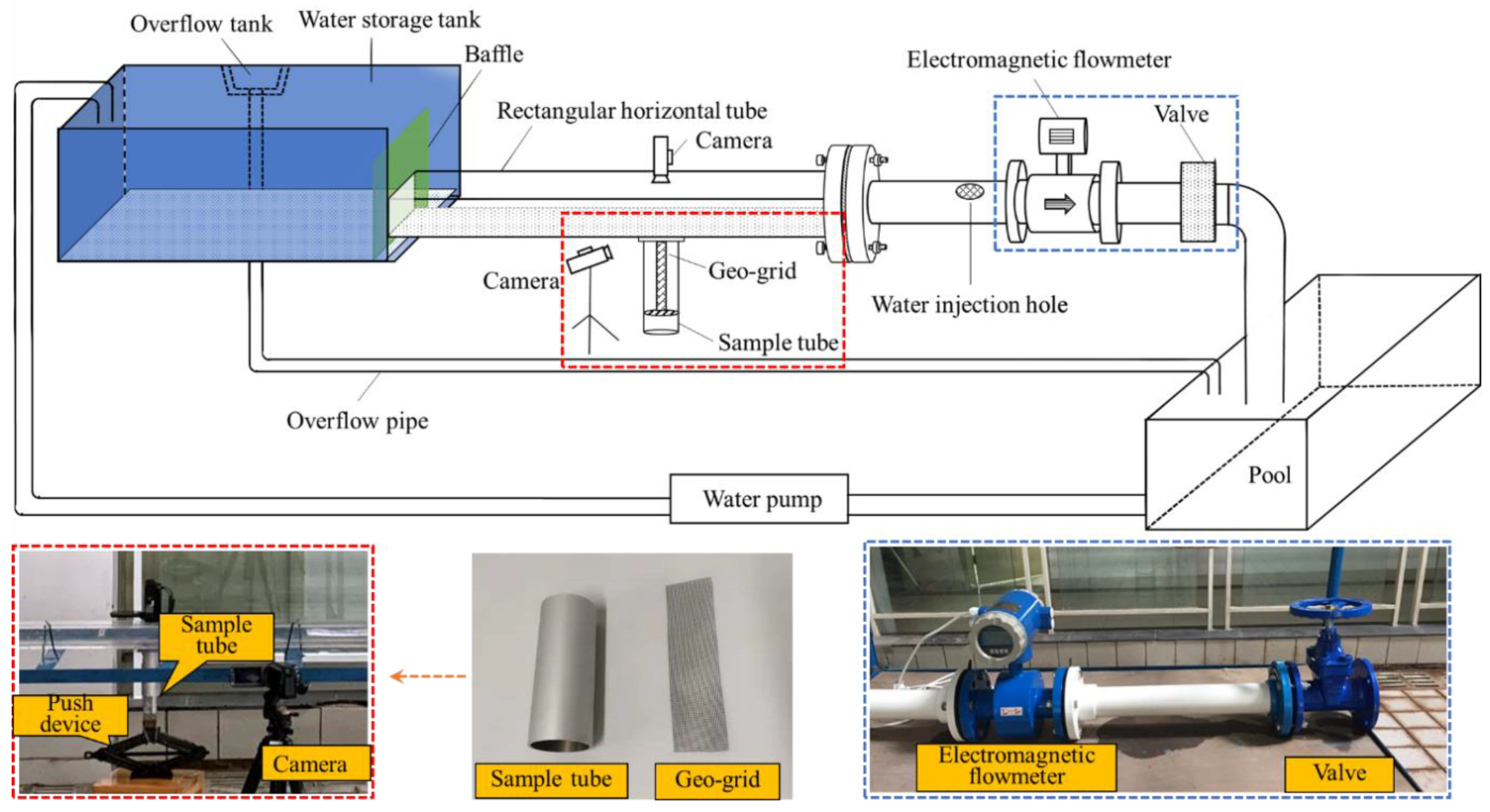
The overall design of the device is shown in Figure 1. The specific design ideas of the device are as follows: (1) A rectangular horizontal tube is made of transparent acrylic material. The size is 180 cm long, 8 cm wide, and 5 cm high. The inner wall is smooth, and the influence of hydraulic roughness can be ignored. (2) The round aluminum alloy cylinder sleeve with a diameter of 5.0 cm is used as the sample tube, and the start-up erosion test of reinforced tailings can be carried out by adding vertical reinforcing strips. (3) Place a jack under the sample tube as the sample pushing device. The piston moves the tailings sample upward by turning the screw rod. The screw rod moves upward by 0.33 mm for each rotation. The sample rises slowly by turning the screw rod by hand for 3~5 circles, and finally makes it flush with the lower surface of the horizontal pipe. (4) Making a glass tank (length × width × height = 2.0 m × 0.6 m × 0.6 m), which can be used as starting water and erosion test water after full storage. (5) The water pump is used as the power unit, with power of 1.5 kW, flow of 40 m3/h, lift of 9 m, and outlet diameter of 80 mm. (6) PVC pipe with DN of 75 cm is selected as the flow pipe. (7) A high-resolution camera (1920 × 1080/50 frames) is used as the observation system to record the sample start-up, erosion height change, and erosion time in real time. (8) The overflow tank can keep the water level constant during the test. (9) The electromagnetic flowmeter is used as the water flow monitoring equipment; the flow rate range is 1.19–119 m3/h and the measurement accuracy is 0.01 m3/h, and the data can be read directly through the electronic display screen.
2.2. Preparation of Reinforced Tailings Samples
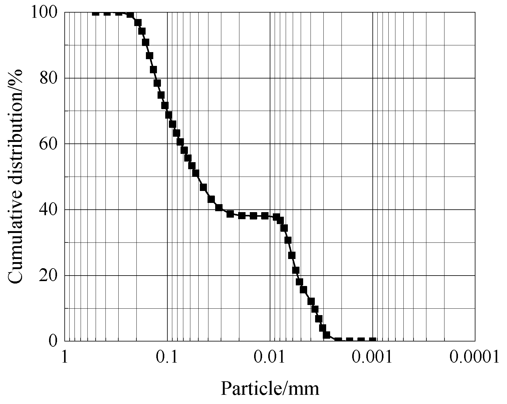
In this incipient motion test, tailings from Yunnan Province were used. The particle size range was 0.005~0.15 mm, and the median particle size was 0.05078 mm. The cumulative distribution curve of particle size is shown in Figure 2.
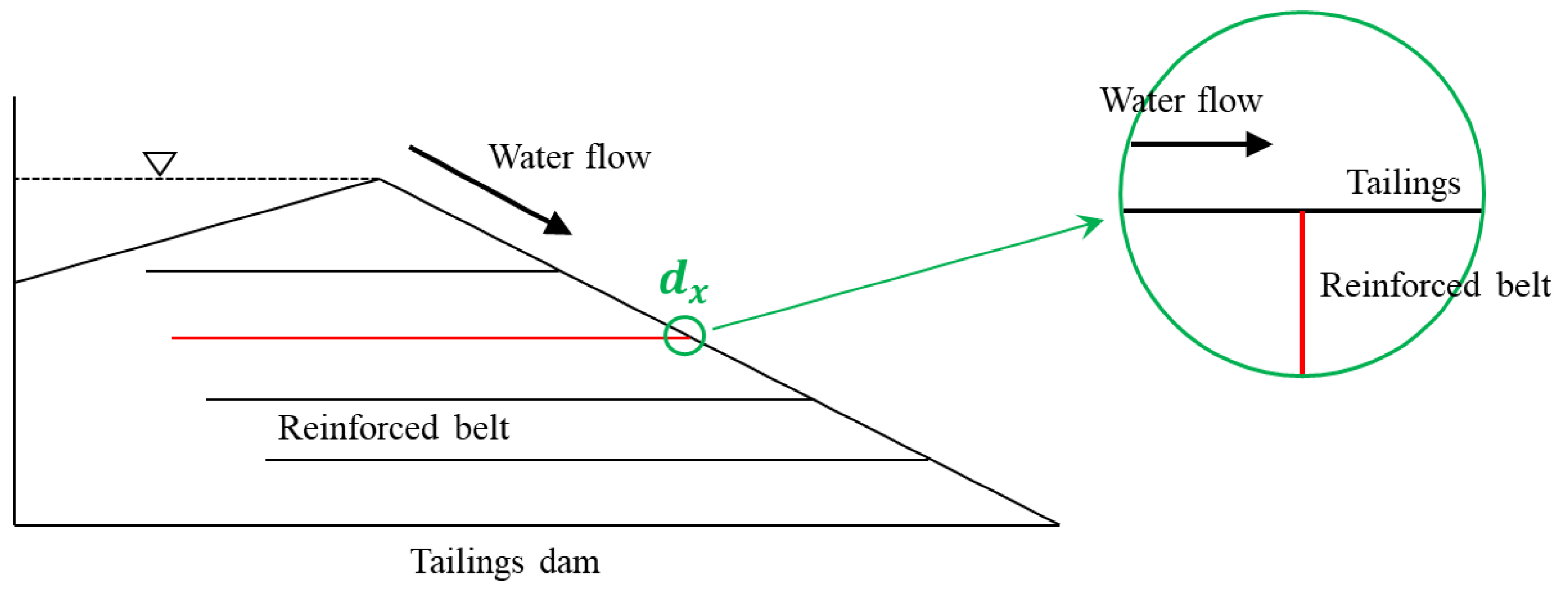
From the indoor reinforced tailings pond overtopping test model, it can be seen that the laying mode of the band in the tailings dam is horizontal laying, as shown in the Figure 3. At the beginning of the overtopping, the water flows along the dam from the top to the foot of the slope, and the tailings particles on the dam begin to be under the condition of water flow. Considering the influence of the belt on the starting of the tailing particles, a small section of near the belt is taken for analysis. When is small enough, and to simplify the experiment, it is assumed that the direction of water flow is perpendicular to the laying of the band, that is, the band is added vertically to the sample tube in this paper.
The incipient motion test steps of reinforced tailings are as follows.
First, preparation of water content: According to the geotechnical test standard, the tailing sample with a water content of 15% is prepared and sealed for 12 h; before the preparation of the sample, a small amount of Vaseline is evenly smeared on the inner wall of the sample pipe to reduce the resistance between the tailing particles and the pipe wall when the sample is pushed during the test.
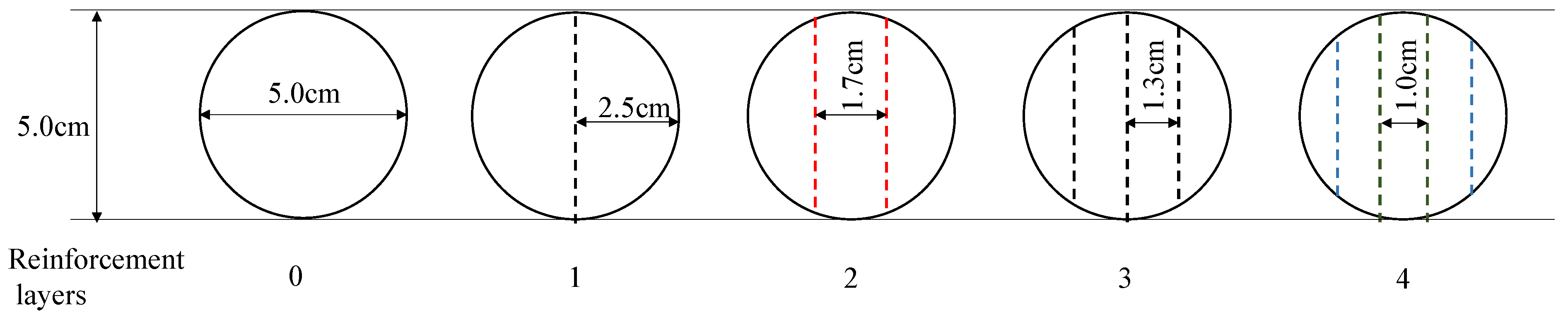
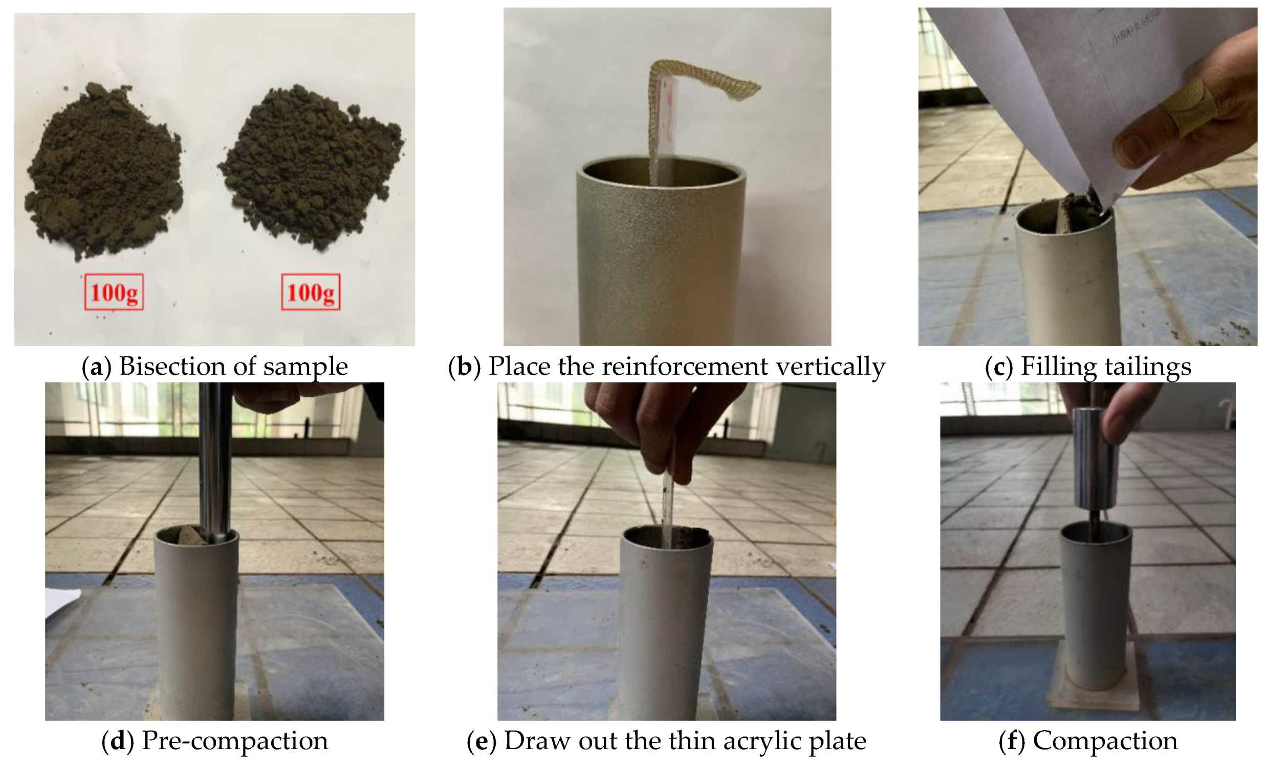
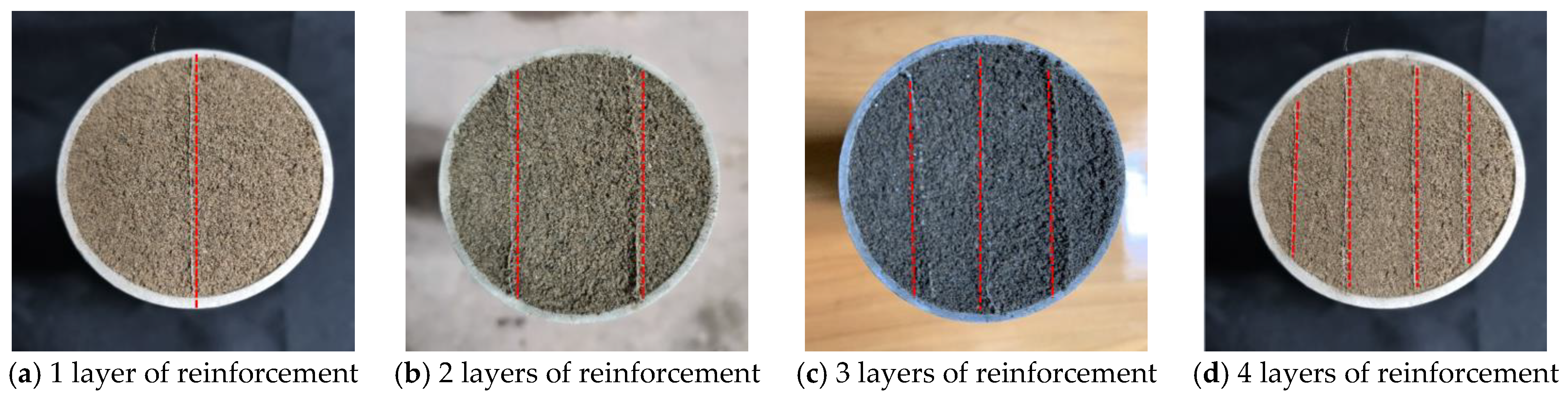
Second, compacted sample: When preparing the unreinforced tailings sample, directly carry out a small amount of compaction treatment to ensure that the compaction of the sample is basically the same. In the preparation of reinforced tailings samples, the reinforcement spacing of the samples is 5.0, 2.5, 1.7, 1.3, and 1.0 cm, respectively. The rib material is glass fiber window screen [26], and its aperture is 1.5 × 1.5 mm2; the function of the thin acrylic plate is to fix the shape of the rib in the sample preparation process, and keep the rib in the sample tube in a vertical state. No folding occurs; see Figure 4 for the specific layout.
Taking one layer of reinforced belt as an example, the whole preparation process of reinforced tailings sample is introduced, as shown in Figure 5. The specific process is as follows: (1) weigh 200 g of tailings sample with good water content and divide it into two parts; (2) place the reinforced belt vertically into the sample pipe after it is attached to the acrylic plate; (3) fill the separated tailings between the reinforced belt and the pipe wall; (4) simply initially compact the samples on both sides of the reinforced belt to ensure that the reinforced belt is vertical during subsequent compaction; (5) place the thin acrylic plate and take it out from the top of the sample tube; and (6) compact the whole reinforced tailings sample with a compaction hammer from the top of the sample tube.
Finally, flattening sample: It is inevitable that a small amount of tailings will be exposed from the bottom of the sample tube in the process of tamping the sample. Therefore, after tamping the sample, it is necessary to flatten the tailings at the bottom of the sample and cut off the exposed reinforcement. The final reinforced tailings sample is shown in Figure 6.
2.3. Experimental Procedures
First, fill a small amount of tailings with a good moisture content into the sample tube many times to prepare samples, and measure the thickness of samples, so as to calculate the density of the prepared samples.
Second, put the round sample tube into the horizontal tube of the incipient motion test device, and adjust the jack manually to make the surface of the sample flush with the bottom of the horizontal tube.
Then, open camera 1, electromagnetic flowmeter, and camera 2; slowly open the valve to make the water flow in the horizontal pipe flow; and start the water pump to re-inject the water into the storage tank, so as to ensure the constant water level.
Finally, slowly increase the valve. When the flow rate increases to a certain value, the tailings particles will start, and record the reading of the electromagnetic flowmeter.
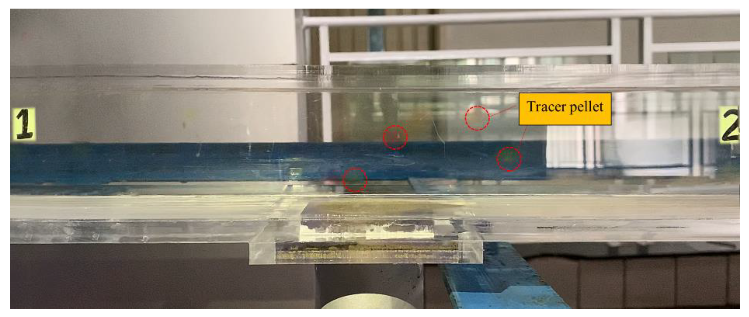
In addition, before the start of the test, it is necessary to verify the reliability of using the electromagnetic flowmeter to calculate the flow velocity. Firstly, during the test, the small balls are put into the horizontal pass from time to time, and then camera 1 is used to take photos. The flow velocity is calculated by the tracing method. In fact, labels 1 and 2, distanced from 0.5 m, are posted on the horizontal tube to facilitate camera 1 to track the small balls, as shown in Figure 7.
Among them, the flow rate Q can be recorded by electromagnetic flowmeter, which can be converted into velocity by formula (1), so as to determine the flow velocity when tailings particles start and erode.
where, is the flow rate, ; is the flow velocity, ; and is the cross-sectional area of the pipeline, . Considering that the inner wall of the horizontal pipe and PVC round pipe is smooth, the influence of hydraulic roughness can be ignored.
After many verification tests, it was found that the flow velocity measured by the tracer method was basically the same as that calculated by the flowmeter, which proves that it was reliable to use the flowmeter to calculate the flow velocity.
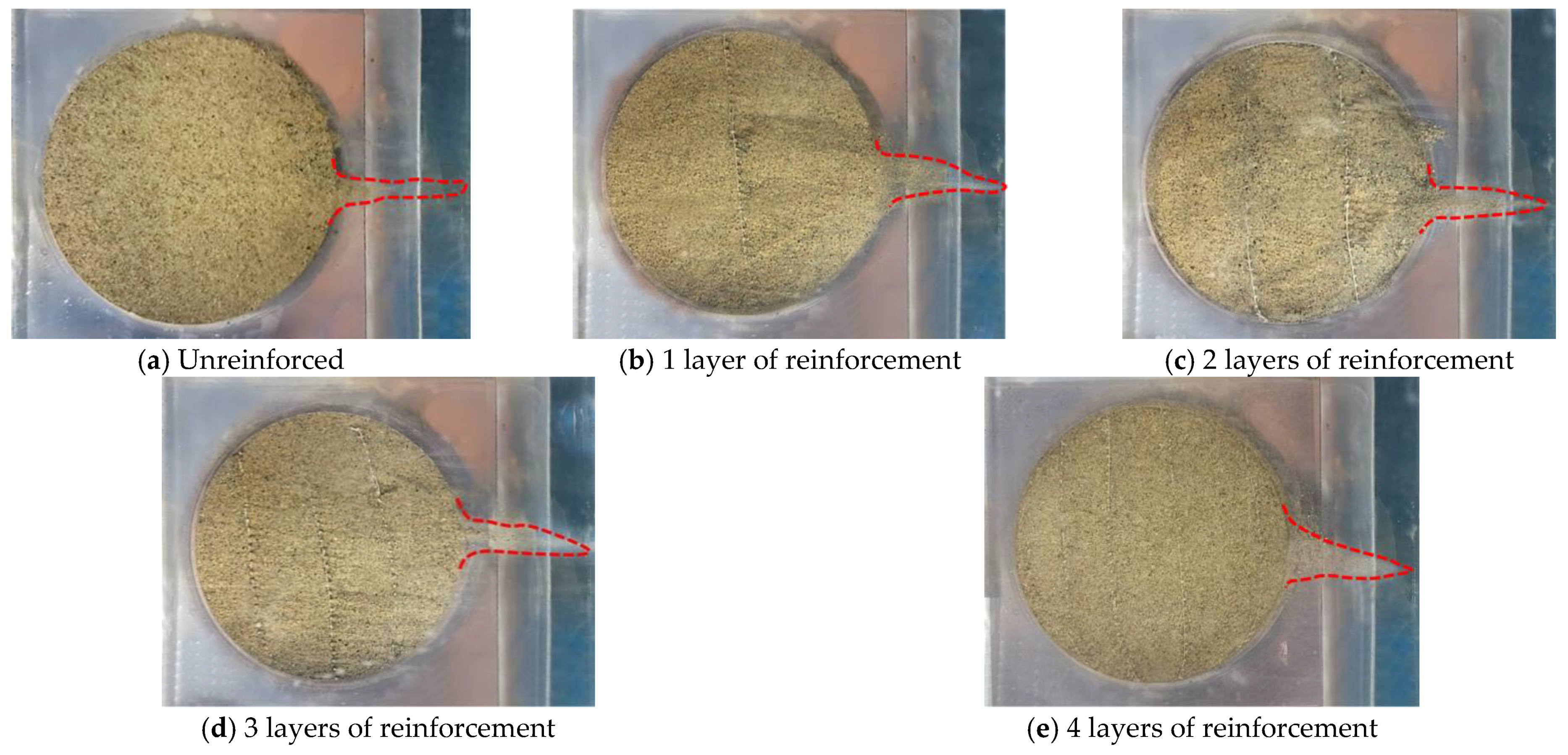
Threshold criteria: The randomness of sediment threshold puts forward a criterion for judging the threshold conditions. At present, a qualitative criterion is widely used in the laboratory, that is to say, a small amount of sediment moving on some bed surfaces is defined as the threshold criteria. The judgment method of sediment particle incipient motion is the visual observation method. Although there is a certain visual deviation, if the same person determines the particle incipient motion during the test, the judgment standard will not be different owing to personal subjective consciousness. At the same time, if the test is observed carefully, the error range is limited. Considering the limitation of test equipment and the simple operation of this method, the visual inspection method is used to judge the incipient motion of reinforced tailings particles. Finally, on the phenomenon of sediment incipient particles, the phenomenon of a thin line of smoke behind the sample is taken as the standard of a small amount of incipient motion for tailings particles; Figure 8 is the incipient motion diagram of tailings with different reinforcement spacing.
3. Incipient Motion Test Results and Analysis
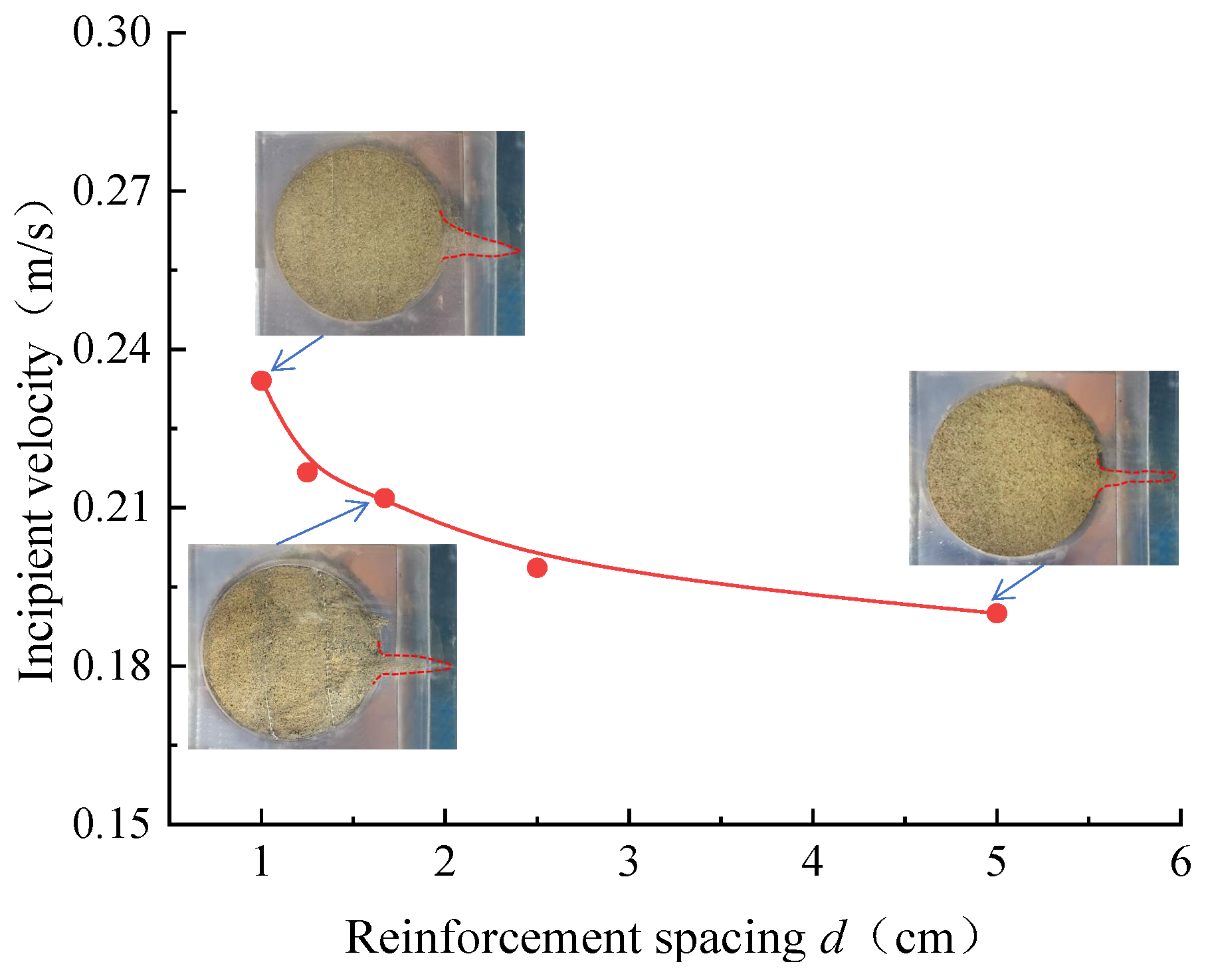
The main purpose of this start-up test is to measure the incipient velocity of tailings particles with reinforcement spacing of 5.0, 2.5, 1.7, 1.3, and 1.0 cm (reinforcement layers of 0, 1, 2, 3, and 4) under the action of water flow. In the process of the test, the density and incipient velocity of the sample were recorded. The incipient motion test of reinforced tailings was carried out under the reinforced spacing of 5.0, 2.5, 1.7, 1.3, and 1.0 cm, and the start-up velocity of reinforced tailings particles was obtained. See Table 1 for details.
The incipient velocity of tailings samples at different reinforcement spacings (5.0, 2.5, 1.7, 1.3, and 1.0 cm) is shown in Figure 9. It can be seen from the figure that the reinforcement spacing has an obvious influence on the incipient velocity of tailings particles. With the increase of reinforcement spacing, the incipient velocity of reinforced tailings particles decreases; the test shows that, when the reinforcement spacing is 2.5 cm, the incipient velocity of reinforced tailings particles is 0.199 m/s, and when the reinforcement spacing is reduced to 1.0 cm, the incipient velocity of reinforced tailings particles increases to 0.234 m/s. According to the quasi cohesion principle of geo-grid reinforcement [27], it can be considered that the tailing added with the reinforcement will increase an additional quasi cohesion, and the quasi cohesion provided by the reinforcement will gradually decrease with the increase of the reinforcement spacing. Therefore, under the action of water flow, the incipient velocity of reinforced tailing particles will decrease with the increase of the reinforcement spacing.
4. Incipient Motion Model of Reinforced Tailings Particles
At present, many studies have been done on the stress and critical incipient velocity of sediment. A large number of incipient velocity formulas are also established, but there is little research on the establishment of the incipient motion model of tailings particles in the process of reinforced tailings dam overtopping erosion. The incipient motion model of reinforced tailings particles is one of the foundations of the study on the asymptotic erosion failure of reinforced tailings dam overtopping, which is of great significance to the prediction of the time of tailings dam overtopping. Therefore, this paper mainly draws on the research results of previous studies on sediment incipient motion. Considering the blocking effect of reinforcement on particles, the reinforcement coefficient is introduced into the incipient motion model of unreinforced tailings particles to establish the incipient motion velocity formula of reinforced tailings particles.
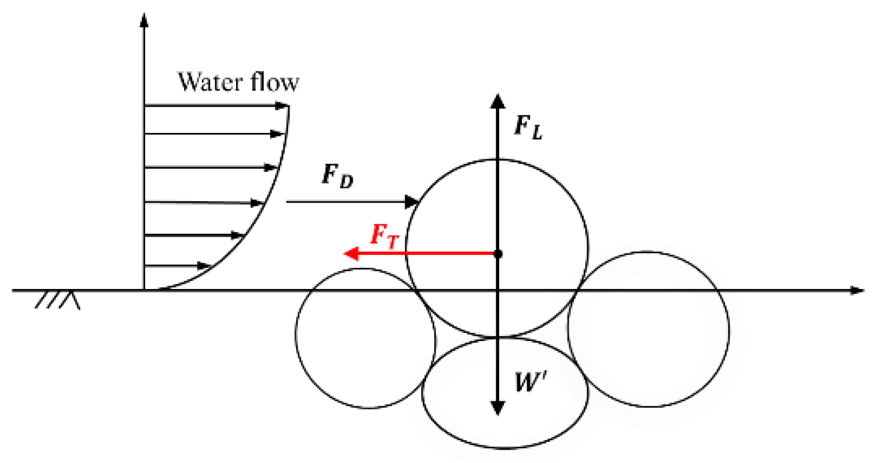
4.1. Force Analysis of Particles
Under the action of water flow, the reinforced tailings particles are not only subjected to effective gravity , drag force , and lift force , but also are subjected to the resistance of the reinforcement belt to the particle incipient motion. Based on runoff erosion mechanics under hedgerow, it is assumed that the resistance is , and the action direction of resistance is opposite to the direction of particle movement. The stress of reinforced tailings particles during incipient motion is shown in Figure 10, and the expressions of each force are as follows:
where, is the Chezy coefficient, . In natural cases, can be assumed to be a constant as a fraction of the thrust of a single sediment; is the ratio of uplift force to flow thrust intensity; is the average velocity; , , and are constants depending on the shape of sediment particles; and is the incipient particle size, m.
4.2. Establishment of Incipient Velocity Formula of Reinforced Tailings
In view of the fact that there is no specific expression of the resistance of the reinforcement to the particles at present, it can be seen that plants provide a resistance and shielding effect when the particles start. Therefore, it is considered to introduce a reinforcement coefficient to modify the incipient velocity formula of Cai [28], so as to obtain the incipient average velocity formula of reinforced tailings particles:
The incipient velocity formula of Cai Rongrong is as follows:
where, is a constant, generally 11.6; is the hydraulic radius, , where a and b are the height and width of the rectangular pipe; n is roughness, ; and is the incipient Reynolds number of sediment.
According to the incipient velocity data of reinforced tailings in Table 1, the incipient velocity of tailings without reinforcement is calculated according to Formula (6). At the same time, the experimental value of the incipient velocity of reinforced tailings particles is used. is calculated by formula (5), which is detailed in Table 2.
Taking into account the non-stiffened tailings incipient motion, that is to say, when the reinforcement spacing is 5.0 cm, there is no reinforcement, so is 1, and when the reinforcement spacing is 2.5, 1.7, 1.3, and 1.0 cm, the reinforcement produces a blocking effect on the particle incipient motion, so the reinforcement coefficient should be greater than 1, and and are plotted for numerical fitting (Figure 11).
It can be seen from Figure 11 that, when the reinforcement spacing d continues to increase, is closer to 1, which means that, with the infinite increase of reinforcement spacing, the influence of reinforcement on tailings particles will almost not exist. Thus, can be obtained by fitting the following:
By substituting Formula (7) into Formula (5), the formula of incipient velocity of reinforced tailings can be obtained, namely,
The confidence intervals of the constant, coefficient, and index in Equation (6) are (0.98, 1.02), (0.44, 0.69), and (0.82, 1.46), respectively.
is shown in Formula (6), as follows:
5. Conclusions
- (1)
- The hydraulic incipient motion tests of tailings with different reinforcement spacing (5.0, 2.5, 1.7, 1.3, and 1.0 cm) were carried out at a reinforced tailings hydraulic erosion facility, specifically developed for this study. It is found that the incipient velocity of reinforced tailings particles increases with the decrease of reinforcement spacing.
- (2)
- Based on the theory of sediment incipient motion, considering the blocking effect of reinforcement on particles, the reinforcement coefficient is introduced, and the formula of incipient velocity of reinforced tailings particles is established.
- (3)
- There is a nonlinear relationship between the reinforcement coefficient, , and the reinforcement spacing, . The reinforcement has little effect on the starting of the tailings particles movement, and only the particles near the reinforcement are strengthened by the reinforcement. When the reinforcement spacing, , is greater than 5 cm, tends to 1, which means that the reinforcement has no effect on the starting of the tailings particles movement.
Author Contributions
Conceptualization, K.L. and X.J.; Methodology, H.C.; Validation, Y.C. and S.W.; Supervision, W.W.; Writing—Original Draft Preparation, X.J. and H.C.; Writing—Review and Editing, L.L. and K.L. All authors have read and agreed to the published version of the manuscript.
Funding
This research is funded by the National Natural Science Foundation of China (Grants No. 51974051, 51804051, and 51804222), the Natural Science Foundation project of Chongqing Science and Technology Commission (No. cstc2018jcyjAX0231), Beijing Natural Science Foundation (No. 8204068), the Post-Funded Projects of Chongqing University of Science and Technology (No. ckhqzz2008005), the Self-made Equipment Foundation of Chongqing University of Science and Technology (No. ZZSB2019013), and the Scientific and Technological Research Program of Chongqing Municipal Education Commission (KJZD-K201901501).
Informed Consent Statement
Informed consent was obtained from all subjects involved in the study.
Data Availability Statement
The data used to support the findings of this study are available from the corresponding author upon request.
Conflicts of Interest
The authors declare no conflict of interest.
References
- Zeng, Q.W.; Xie, D.R.; Su, J.D.; Yuan, M. Risk analysis of dam failing of the tailings reservoir. Ind. Saf. Environ. Prot. 2010, 36, 44–46. [Google Scholar] [CrossRef]
- Hao, X.J.; Du, W.S.; Zhao, Y.X. Dynamic tensile behavior and crack propagation of coal under coupled static-dynamic loading. Int. J. Min. Sci. Technol. 2020, 30, 659–668. [Google Scholar] [CrossRef]
- Strawling, C.; Zhang, S.H.; Zhang, X.Y. Operational characteristics of tailings dams. Foreign Met. Mines 2002, 4, 36–42. [Google Scholar]
- Wu, Z.H.; Mei, G.D. Statistical analysis of tailings pond accidents and cause analysis of dam failure. China Saf. Sci. J. 2014, 24, 70–76. [Google Scholar]
- Dang, X.Z.; Gao, M.S.; Zhang, L.T.; Wang, X.G.; Zhang, S.X. Experimental study on the model of flood overtopping and dam break of a tailing pond under different deposit compactness. Mar. Geol. Front. 2018, 34, 79–84. [Google Scholar]
- Wang, G.J.; Tang, Y.J.; Du, C.; Kong, X.Y. Experimental study on dam break under water level variation in reservoir. J. Sediment Res. 2018, 43, 67–73. [Google Scholar]
- Zhang, X.K.; Sun, E.J.; Li, Z.X. Experimental study on evolution law of tailings dam flood overtopping. China Saf. Sci. J. 2011, 21, 118–124. [Google Scholar] [CrossRef]
- Jing, X.F.; Chen, Y.L.; Xie, D.; Williams, D.J.; Wu, S.W.; Wang, W.S.; Yin, T.W. The Effect of Grain Size on the Hydrodynamics of Mudflow Surge from a Tailings Dam-Break. Appl. Sci. 2019, 9, 2474. [Google Scholar] [CrossRef] [Green Version]
- Jing, X.F.; Pan, C.S.; Chen, Y.L.; Li, X.F.; Wang, W.S.; Hu, X. Improvement Effect of Reticular Glass Fibers on the Mechanical Properties of Tailings Sand with the Lenticle (Layered Sandy Soil). Water 2021, 13, 1379. [Google Scholar] [CrossRef]
- Froehlich, D.C. Embankment-dam breach parameters. Am. Soc. Civ. Eng. 1987, 65, 132–138. [Google Scholar]
- Hanson, G.J. Physical modeling of overtopping erosion and breach formation of cohesive embankments. Trans. ASAE 2005, 48, 1783–1794. [Google Scholar] [CrossRef]
- Shakesby, R.A.; Whitlow, J.R. Failure of a mine waste dump in Zimbabwe: Causes and consequences. Environ. Geol. Water Sci. 1991, 18, 143–153. [Google Scholar] [CrossRef]
- Gens, A. Aznalcollar dam failure part 2: Stability conditions and failure mechanism. Geotechnique 2006, 56, 185–201. [Google Scholar] [CrossRef] [Green Version]
- Maria, T.Z.; Luciano, A.O. The role of capillary water in the stability of tailing dams. Eng. Geol. 2009, 105, 108–118. [Google Scholar] [CrossRef]
- Jing, X.F.; Zhou, X.; Zhao, Y.S.; Liu, K.H.; Ye, C.; Pan, C.S. Study on influence of reinforcement density on overtopping failure of tailings dam. J. Saf. Sci. Technol. 2016, 12, 68–74. [Google Scholar] [CrossRef]
- Jing, X.F.; Chen, Y.L.; Dacid, J.W.; Marcelo, L.S.; Hengwei, Z. Overtopping failure of a reinforced tailings dam: Laboratory investigation and forecasting model of dam failure. Water 2019, 11, 315. [Google Scholar] [CrossRef] [Green Version]
- Einstein, H.A. Formula for the transportation of bedload. ASCE 1942, 107, 561–597. [Google Scholar]
- Sundborg, A. The river klarlven a study of fluvial processes. Geogr. Ann. 1956, 38, 125–316. [Google Scholar] [CrossRef]
- Kuhan, E.R.A. Incipient motion of sand-gravel sediment mixtures. ASCE J. Hydraul. Eng. 1993, 119, 1400–1415. [Google Scholar] [CrossRef]
- Roberts, J.; Jepsen, R.; Gotthard, D. Effects of particle size and bulk density on erosion of quartz particles. J. Hydraul. Eng. 1998, 124, 1261–1267. [Google Scholar] [CrossRef]
- Qian, N.; Wan, Z.H. Mechanics of Sediment Movement; Science Press: Beijng, China, 1983; pp. 237–240. [Google Scholar]
- Li, B.R. Calculation method of incipient velocity of sediment. J. Sediment Res. 1959, 1, 73–79. [Google Scholar]
- Sha, Y.Q. Introduction to Sediment Movement; China Industry Press: Beijng, China, 1965. [Google Scholar]
- Sun, Z.L.; Zhang, C.C.; Huang, S.H.; Liang, X. Scour of cohesive nonuniform sediment. J. Sediment Res. 2011, 3, 44–48. [Google Scholar]
- Zhang, H.W. A unified formula for incipient velocity of sediment. J. Hydraul. Eng. 2012, 43, 1387–1396. [Google Scholar]
- Tang, J.X.; Yin, G.Z.; Wei, Z.A.; Wan, L.; Zhang, D.M. Model test study about fine grained tailings dam of longdu tailings pon. China Min. Mag. 2004, 13, 54–56. [Google Scholar] [CrossRef]
- Yang, G.Q. Geogrid Reinforced Soil Structure Theory and Engineering Application; Science Press: Beijng, China, 2010. [Google Scholar]
- Cai, R.R.; Zhang, L.H.; Zhang, H.W. Modificantions to Li Baoru’s sediment incipint velocity formula. J. Hydraul. Eng. 2019, 50, 547–554. [Google Scholar] [CrossRef]
Figure 1.
Reinforced tailings incipient motion test facility.

Figure 2.
Cumulative distribution curve of particle size of the tailings sample.

Figure 3.
Laying method of the reinforcement belt in the reinforced tailings dam.

Figure 4.
The layout of reinforcement.

Figure 5.
Preparation process of the reinforced tailings sample.

Figure 6.
Sample diagram of reinforced tailings.

Figure 7.
Velocity measurement by the tracer method.

Figure 8.
Incipient motion diagram of tailings particles with different reinforcement layers.

Figure 9.
Relationship between incipient velocity of reinforced tailings particles and reinforcement spacing.
Figure 9.
Relationship between incipient velocity of reinforced tailings particles and reinforcement spacing.

Figure 10.
Force analysis of reinforced tailings particles.

Figure 11.
The fitting curve of the reinforcement coefficient f(d).


Table 1.
Incipient motion test data of reinforced tailings.
| Median Diameter (mm) | d (cm) | Mass (g) | Sample Height (cm) | Density (g/cm3) | Flow Rate (m3/h) | Incipient Velocity (m/s) | |
|---|---|---|---|---|---|---|---|
| 0.05 | 5.0 | 155 | 3.8 | 2.08 | 2.74 | 0.190 | 2909 |
| 2.5 | 212 | 5.2 | 2.08 | 2.86 | 0.199 | 3046 | |
| 1.7 | 211 | 5.2 | 2.07 | 3.05 | 0.212 | 3245 | |
| 1.3 | 214 | 5.3 | 2.06 | 3.12 | 0.217 | 3322 | |
| 1.0 | 210 | 5.1 | 2.10 | 3.37 | 0.234 | 3582 |
Table 2.
Reinforcement spacing and reinforcement coefficient.
| Median Diameter D (mm) | d (cm) | (m/s) | (m/s) | |
|---|---|---|---|---|
| 0.05078 | 5.0 | 0.187 | 0.190 | 1.016 |
| 2.5 | 0.187 | 0.199 | 1.064 | |
| 1.7 | 0.186 | 0.212 | 1.140 | |
| 1.3 | 0.186 | 0.217 | 1.167 | |
| 1.0 | 0.188 | 0.234 | 1.245 |
Publisher’s Note: MDPI stays neutral with regard to jurisdictional claims in published maps and institutional affiliations. |
© 2021 by the authors. Licensee MDPI, Basel, Switzerland. This article is an open access article distributed under the terms and conditions of the Creative Commons Attribution (CC BY) license (https://creativecommons.org/licenses/by/4.0/).
Share and Cite
MDPI and ACS Style
Liu, K.; Cai, H.; Jing, X.; Chen, Y.; Li, L.; Wu, S.; Wang, W. Study on Hydraulic Incipient Motion Model of Reinforced Tailings. Water 2021, 13, 2033. https://doi.org/10.3390/w13152033
AMA Style
Liu K, Cai H, Jing X, Chen Y, Li L, Wu S, Wang W. Study on Hydraulic Incipient Motion Model of Reinforced Tailings. Water. 2021; 13(15):2033. https://doi.org/10.3390/w13152033
Chicago/Turabian StyleLiu, Kehui, Hai Cai, Xiaofei Jing, Yulong Chen, Lu Li, Shangwei Wu, and Wensong Wang. 2021. "Study on Hydraulic Incipient Motion Model of Reinforced Tailings" Water 13, no. 15: 2033. https://doi.org/10.3390/w13152033
Note that from the first issue of 2016, this journal uses article numbers instead of page numbers. See further details here.