
Analysis of Applicability of CFD Numerical Studies Applied to Problem When Pump Working as Turbine


1
Departamento de Ingeniería Civil y Ambiental, Escuela Politécnica Nacional, Quito 170525, Ecuador
2
Departamento de Ingeniería Mecánica, Escuela Politécnica Nacional, Quito 170525, Ecuador
3
Laboratorio de Mecánica-Informática, Escuela Politécnica Nacional, Quito 170525, Ecuador
4
Carrera de Pedagogía Técnica de la Mecatrónica, Facultad de Filosofía, Letras y Ciencias de la Educación, Universidad Central del Ecuador, Quito 170129, Ecuador
5
Hydraulic and Environmental Engineering Department, Universitat Politècnica de València, 46022 Valencia, Spain
*
Author to whom correspondence should be addressed.
Water 2021, 13(15), 2134; https://doi.org/10.3390/w13152134
Submission received: 8 June 2021
/
Revised: 28 July 2021
/
Accepted: 29 July 2021
/
Published: 3 August 2021
(This article belongs to the Special Issue Hydropower and Pumping Systems)
Abstract
:The present research depicts an analysis of the implementation of computational fluid dynamics (CFD) in the study of pumps such as turbines and PATs. To highlight the benefits of CFDs for PAT studies, results from both experimental tests have been compared to better understand the reproduction error phenomena. For this, data analysis used in successful models has been applied to determine variables and parameters, and to report a low relative error. The results show that most of the studies focused on fixed speed rotation with some cases of variable speed rotation. Furthermore, there is not enough information in the academic literature for PAT of axial and mixed flows with fixed and variable speed. Finally, turbulence models based on Reynolds average Navier–Stokes (RANS) have been used to simulate PATs with fixed speed rotation in most cases.
1. Introduction
The improvement of the sustainability applied to water systems is mainly focused on the increase in energy efficiency [1]. This improvement is quantified by the measurement of the indicators such as applied energy, dissipated energy by valves, friction losses, the minimum energy required, among others [2]. When a water system is evaluated by audit, one of the most significant sectors of the energy balance is the dissipated energy, which is carried out using pressure reduction valves (PRVs) [3]. The replacement of these valves by recovery systems is a solution to improve the energy balance of the water systems and to increase the use of clean technologies to satisfy the demand of one’s own systems for the evolution to reach the maximum level of self-consumption [4].
When the use of the recovery systems was considered, the use of pump working as turbine (PATs) was an excellent solution in terms of its hydraulic operation, feasibility and easier management compared to classical machines (e.g., Francis and Pelton), which have higher efficiencies than PATs but are more expensive [5]. These aspects caused the implementation of PAT technology, which increased in recent years in some engineering applications such as irrigation, hydraulic power stations, water supply, and energy recovery systems [6,7,8]. Moreover, water pressure control and water management are applied as environmental solutions according to previous studies [9,10,11,12]. In this context, one of the main goals of previous studies was to obtain performance curves for PATs [7].
Considering the increased use of PATs in various engineering and industry applications and that the manufacturers do not provide the performance curves in turbine mode [7], further research has been carried out using multiple methodologies to obtain the characteristic curves of the pumps working in this mode. The different methods used are theoretical analyses, mathematical models, numerical simulations with CFDs, experimental tests, and empirical expressions. As an example of mathematical analysis, Plua et al. [13] proposed a new PATs prediction model that can be used in different hydraulic simulation software. However, the majority of the previous studies only focused on the operation under fixed rotational speed, whereby published researches showed the need to operate under variable rotational speed considering both hydraulic and electrical regulation [14]. Some of the researchers used numerical methods to evaluate the goodness of these recovery systems. In this sense, computational fluids dynamics (CFD) becomes an important tool for investigating internal flow and performances during turbo-machinery design [15].
Axial, mixed, and radial PATs have been studied using CFD simulations for fixed and variable speeds [8,10,11]. Results showed good agreement among parameters while comparing simulations with experiments for pump and turbine operation mode highlighted that the hydraulic efficiency is practically the same for both operation mode in some cases. To achieve the convergence of solutions, the grid mesh takes a very important part in the aforementioned studies. Moreover, Binama et al. [7] proposed the improvement of mesh quality to identify the losses in different parts of PATs. Rawal [8] suggests that, to obtain accuracy, convergence on CFD results with experimental data is a necessary experience for researchers. In this context, an unstructured mesh could give accurate simulation results. However, a structured mesh should be applied to capture some details, which are important to determine losses in PATs.
According to Fecarotta et al. [16], the CFD technique allows modellers to understand the field flows and the operating conditions for PATs with high accuracy and a low cost in comparison to other experiments. Therefore, the continuum considerations used in CFD to solve Navier–Stokes equations (NS) are the most common way to perform numerical simulation for hydraulic machinery [17,18]. However, the experimental part is necessary to calibrate CFD numerical models and to obtain reliable results in PATs under different optimization stages [15,19,20,21].
As aforementioned, the NS is solving for CFD simulation using a turbulence model to understand the flows field behavior in PATs [15,19]. For that, turbulence models are numerical techniques to optimize computational time resources and data storage [17]. The Reynolds average Navier–Stokes (RANS) and the large-eddy simulation (LES) are the more popular general turbulence models for NS in hydraulic machinery [17]. RANS models aim to obtain the average behavior of the internal flows in PATs with a lightweight computational mesh and unstructured characteristics [19]. On the other hand, large-eddy structures inside of an impeller could be obtained using LES with a complex structured mesh and more use of computational resources than RANS [18].
The present research aims to evaluate the application of numerical CFD simulation studies in PATs through a literature survey. Then, based on the relative error calculation between their results and the experiments, practical conclusions for the future numerical analysis of PATs are obtained. In addition, it is debated if this technique has been sufficiently applied in the different types of pumps and under the fixed or variable speed operating modes. The knowledge of its applicability will enable to establish future developments, which should be tackled by researchers, engineers, and companies the increase the sustainability in energy terms in the water pressurized systems.
2. Materials and Methods
Numerical simulations of PATs were based on a continuum mechanics approach for fluid mechanics [18]. For that, Navier–Stokes equations were solved using CFD methods. Thus, equations of mass conservation and linear momentum are indicated in a tensor description as following expressions:
where i and j are subscripts for the three-axis of space, respectively, u is the velocity magnitude in each direction in m/s, ρ is the fluid density in kg/m3, P is the static pressure tensor in N/m2, τ is the viscous stress tensor in kg/m2, t is time in s, and a is related to an external acceleration in m/s2, which affected the gradient pressure such as the gravity.
Those two equations were considered to solve velocity and pressure using finite volume techniques in all studies cases. The boundary conditions were based on Equation (2) of the variation of linear momentum. Therefore, the inlet path is a velocity magnitude, the outlet path is a static pressure value, the friction tensor is represented as no-slip walls to consider the effects of dynamics viscosity, μ, and the external acceleration is equal to zero due to the fact that the gravity is orthogonal to the fluid motion.
Equations (1) and (2) enable the definition of the average behavior of flows inside of PATs in all of the CFD simulations and to simplify solving equations. The filtered approach is indicated as [18]:
where is the filtered velocity and is the filtered pressure. Moreover, the following considerations were taken into account:
- The product of filtered velocities is
- The subgrid stress tensor is
- The filtered stress tensor rate is
- The filtered viscous stress tensor is
According to [10], is a nonlinear term and it can be solved using turbulence models such as RANS, ILES, or mixture models. Structured and unstructured meshes were applied for the studies of PATs similar to Figure 1a, which shows a Francis turbine grid mesh [22]. This mesh was constructed through a multiblock approach made in previous studies that were modified to obtain higher quality. The quality of mesh was verified with the check mesh tool and Ω, and y+ parameters.
The rotating mesh in the studies were used to consider interfaces connections, allowing the relative motion between volumes and elements. The arbitrary mesh interface (AMI) was applied for the interpolation of adaptive meshes to reduce continuity errors and improve its numerical efficiency. Based on Galerkin’s projection, this approach creates an intermediate mesh from two consecutive time-step meshes. Its approach is similar to general grid interface (GGI); however, the AMI method is more computationally efficient. According to [23], this algorithm is robust and stable for the case of complex meshes. An example of AMI interfaces is presented in Figure 1b.
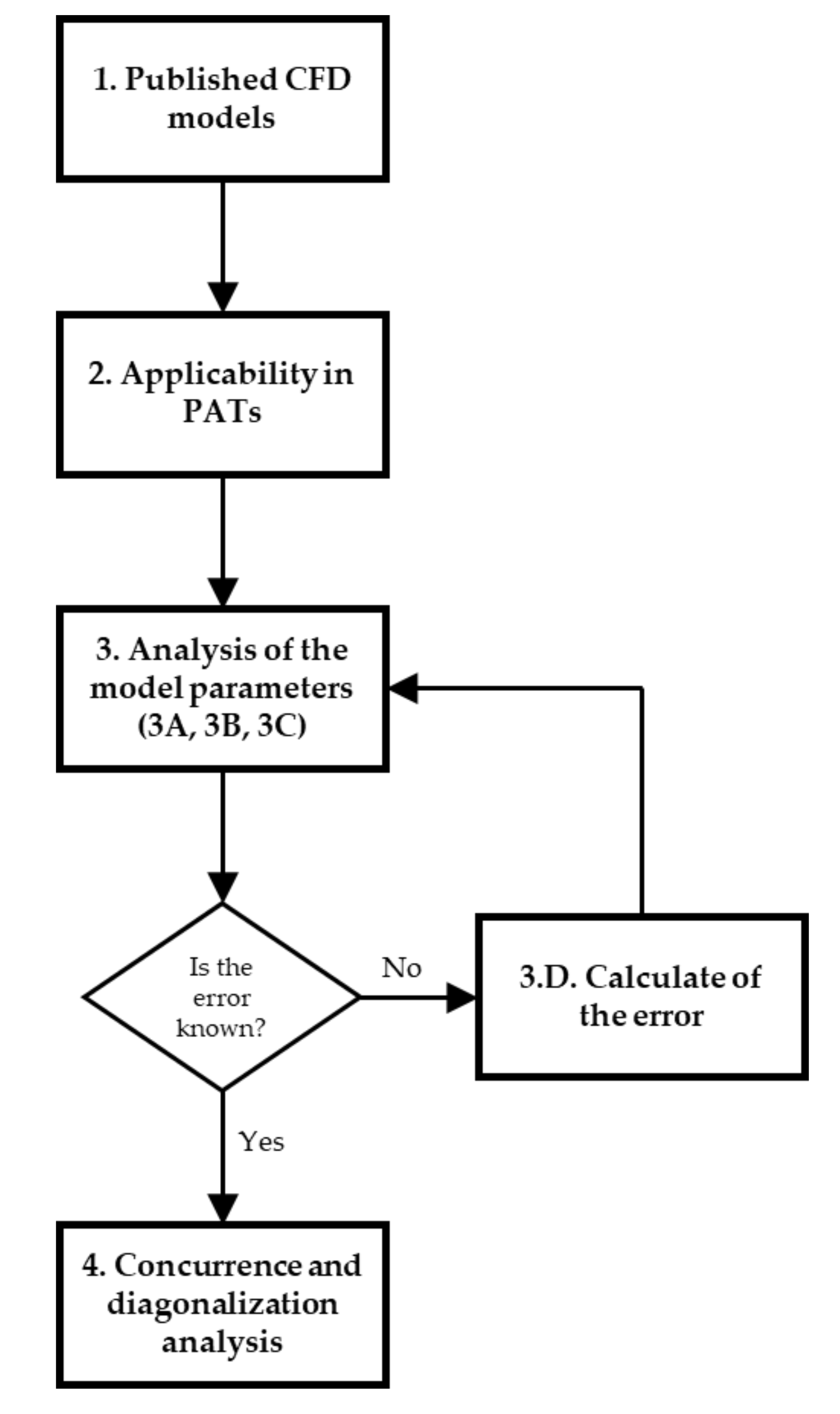
Based on the aforementioned descriptions of the PATs studies, Figure 2 depicts the methodology implemented in the present research. The steps followed in this methodology are the following:
- 1.
- Collection of information. Recent studies related to PATs research were found. A deep search was developed to do a great database, which helps to analyze the different published CFD analyses applied to pump working as turbine.
- 2.
- Selection of relevant information for this study. The papers of interest should be related to numerical simulation CFD applied to PATs: experimental studies, theoretical, mathematical models, new proposals for obtaining the characteristic curves of the pumps, studies of optimization of component elements, state of the art, studies of PATs for machine speeds fixed or variable, among others.
- 3.
- Information Analysis. The information consulted and collected from the studies analyzed is described below:
- Step 3A. From the CFD numerical simulation studies, the information obtained was: pump type-axial, radial or mixed; fixed or variable speed; rotational speed value; specific speed value; CFD package; boundary conditions at the entrance or exit of the machine; the turbulence closure model; mesh-type; and simulation results.
- Step 3B. The main results of the experiments were obtained from the experimental research.
- Step 3C. From the other studies, the results and conclusions obtained from different investigations were used to discover more about new applications and optimizations.
- Step 3D. Calculation of the relative error. In cases where both numerical simulation and experimental test results were obtained for the same conditions, the maximum relative error between the experiment and the numerical simulation was calculated according to the following equation:where and are the values of the parameters in the experiment and the numerical simulation, respectively. These parameters or study variables are specified in the nomenclature part of this paper corresponds to the values that different researchers have compared between numerical modelling CFD and experimental tests. These values will serve as a reference to evaluate the success of modelling.
It should be noted that this calculation of the parameters with the maximum dispersion were considered to obtain the significant values. For some cases, the papers directly reported these values. - 4.
- Concurrency and diagonalization. Based on the information collected and the results of the calculations, a concurrency and diagonalization analysis was performed to identify the number of investigations according to the type of PATs and to identify the main CFD modelling parameters used in successful experiences.
3. Results and Discussion
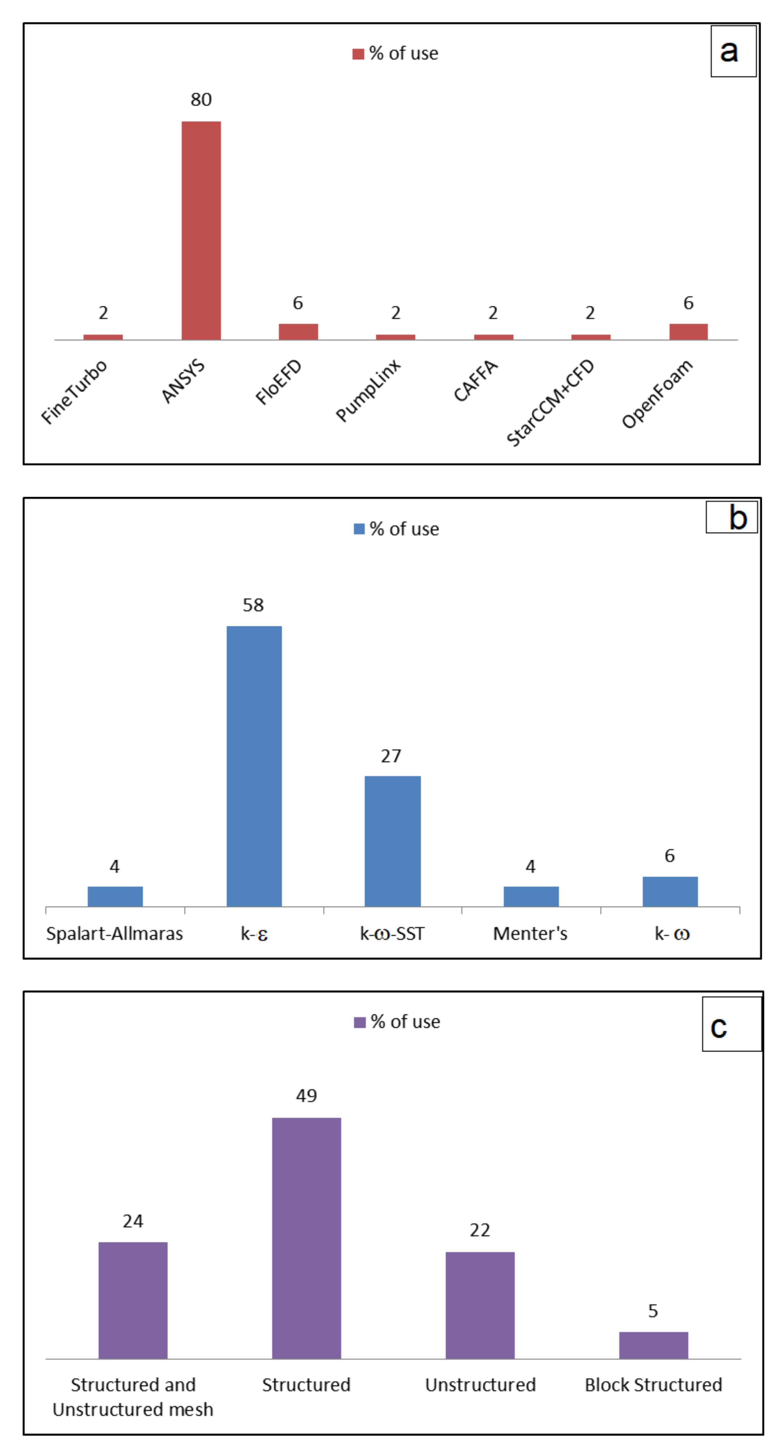
3.1. CFD Model Applied in PATs Simulations
In Figure 3a, it can be observed that the CFD computational package was mostly used for numerical models in PATs is ANSYS, as well as the preferred turbulence closure model is k-ε (Figure 3b). Figure 3a shows the most used software is the ANSYS package, while the use of free software such as OpenFoam is used less than 10% of the published research. In this sense, the development of methodologies, which can establish improvement in the development of meshes, as well as the development of CAD tools to make these meshes in OpenFoam, will help to introduce more researchers in the use of free packages as OpenFoam.
Figure 3b shows the most used turbulence closure model is k-epsilon. It represented 58% of the analyzed case studies. The k- was used in 27% of the analysed case studies and the rest of the turbulence models were used between 4% and 6%.
As shown in Figure 3a, the proprietary program ANSYS presents ease of handling, ease of simulation structure, and mesh optimizations through its accompanying software for CFD problems. On the other hand, the FloEFD software has the advantage of handling different programs in a single package, so it presents excellent ease of use. Finally, OpenFOAM benefited from being a free software package that could be adapted according to our specific needs [24], which gave it a significant advantage over the rest. To solve the RANS equations, the most used models in turbomachinery were k-ε and k-ω-SST (Figure 3b), which coincides with previous studies [22,25] due to the benefits they represent in terms of reproduction of flow phenomenon in PATs as well as computational consumption [18]. Furthermore, in these closure models, viscous effects were taken into account, allowing for greater accuracy of the results of numerical models.
The previous idea is also related to what is observed in Figure 3c. The structured mesh was the most used because it presented the most accurate results and captured the viscous effects [22]. The structured mesh was obtained from the multi-block approach. So, it is shown that the application of a structured mesh and an appropriate closure turbulence model allows captures the viscosity effects, and the fluid in PATs can be well simulated.
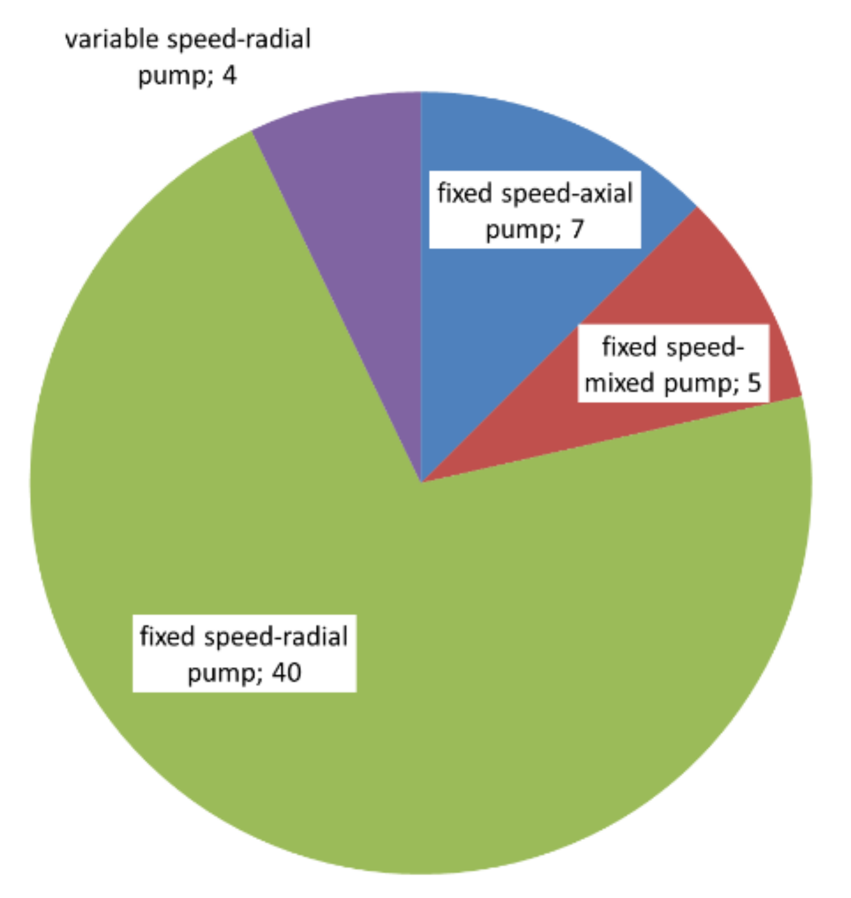
As shown in Table 1 and Figure 4, there are many investigations on PATs for radial flow pumps with fixed rotation speed and very few for variable rotation speed. However, this type of centrifugal pump is the only one that has been studied for this speed condition. The number of papers which show report numerical models for pumps with the mixed flow and axial flow is much lower compared to the radial. However, it is observed that, in recent years, different studies have been made for this type of machine.
The limited amount of research conducted on PATs in mixed and axial pumps (Figure 4) indicates that this field of study needs to be expanded to determine the feasibility of using this machinery in the applications mentioned above. The use of these machines is justified when the heads are low and the flow has high values [75]. In many real situations, the axial machines would adapt correctly, but the lack of previous experimental tests causes the water managers to have few analytical expressions to estimate the energy analysis using axial PATs [13].
Most centrifugal pumps, regardless of their specific speed, flow direction, and the number of impellers, can work in turbine mode to recover and generate energy. The consulted studies were classified by type of machine and type of rotational speed (fixed or variable) to find successful CFD applications in PATs and to find fields of research that have not been sufficiently studied. On the other hand, anticipating that the operation of the PATs will be in conditions of variable flow and recoverable height, it is necessary to know the strategies that can be used to establish hydraulic and electrical regulation in a system through machine arrangements and speed control. For this reason, the advances of numerical modelling must be understood to find expressions and relationships of prediction of the functioning of the PATs in this aspect.
3.2. Analysis of CFD Simulation When PAT Operated under Fixed Rotational Speed
In analyzing PATs with axial pumps (high specific speed values), it is necessary to point out that applying this type of pump is for large flow values with low heads. It is essential for their testing in large laboratory setups. In this type of pump, White [26] compared a test for a high specific speed 230.8 rpm (m,kW) and CFD simulation, which results in a calculated relative error from 12.5% to 84% in PAT mode for the H/HBEP relationship. According to this author, the difference between tested and simulated pumps is because both pumps were not identical. For the CFD simulation, there were simplifications in the elaboration of the machine’s geometry and the staging interface. The software used in the numerical simulation was CFX Turbogrid-2.2.
Table 2 shows a summary of the main parameters which were used and obtained in the CFD simulations. The analysis of these parameters as well as the considerations in the different published research are used in the following discussion. The mentioned parameters or study variables allow evaluating the effectiveness of numerical modelling compared to the experimental results carried out in PATs research. These parameters are indicated in the Nomenclature part of the paper.
Pienika [30] investigated an axial pump with the help of open-Code (CAFFA3d) created at the School of Engineering of the University of the Republic of Uruguay. The boundary conditions at the inlet and outlet were uniform pressure and mass flow, respectively. The experimental test was executed in the Laboratory of the School of Engineering of the University of la Plata. The maximum calculated relative error reached in H was 2.1%. Woo [29] presented research with multi-objective optimization for a counter-rotating axial type pump-turbine operated in both direct and reverse modes. The numerical simulation was performed with package ANSYS, with boundary conditions mass flow rate and atmospheric pressure in the inlet and outlet, respectively. The turbulence closure model was k-ω-SST, and the mesh was hexahedral. The reported relative error was less than 1% for the efficiency.
Kerschberger [27] has developed an inverse design method to optimize and redesign the blade profile. A simulation was carried out with ANSYS CFX5 V12, used a mixed mesh with structured and unstructured elements, and its closure model was k-ω. Renzi [28] conducted a case study of an axial flow pump in direct and reverse mode in a wastewater sewer to place it in a treatment plant. The simulation was executed with the ANSYS Workbench package a PAT with a rotational speed of 260 rpm and used a closure model k-ω-SST. The boundary conditions were mass flow rate per vane in the inlet section and gauge pressure in the outlet section. Finally, Carravetta [11] simulated unsteady flow calculations for three different closure times of the stroking valves only for pump mode. None of these three studies carried out experimental research to verify the CFD simulations performed.
Although it is not so common to employ centrifugal pumps with the mixed flow for PATs, according to Hlbocan [31], mixed flow pumps with a vane diffuser might be employed in a turbine operation mode without any troubles. This author used a CFD modelling for a pump with = 257 rpm (m,kW) and a n = 1800 rpm. The computational grid was composed of 2.5 million hexahedral elements, and a transient simulation was executed. The boundary conditions were for both pump and turbine modes, static pressure at the outlet, and mass flow at the inlet. The selected closure turbulence model was k-ε.
Capurso [32,33,34] conducted three investigations on double suction centrifugal pumps, which have a specific speed of = 21 rpm (m,kW). The simulations were developed using OpenFOAM and were applied to run in transient simulations, including moving meshes for incompressible flow in pump and turbine modes. In the first study [32], the flow in the impeller at the exit was analyzed considering the slip factor. In the second paper [33], the authors extended their research on the slip phenomenon, which developed a 1D performance prediction that allows reducing the prediction error for the experiments on the pump for a similar specific speed by 5% of the design point compared to a non-slip model. To establish comparisons between the modelling and the experiment for the H/HBEP parameter, relative errors of 2.4% and 4.8% were obtained, respectively. The third work [34] presented the design of a new impeller that optimizes the operation of the PAT and carried out an analysis of cavitation and NPSHr at PATs under different operating conditions. For all cases, the boundary conditions were mass flow rate at the inlet and uniform pressure distribution at the outlet, the rotation speed was 3900 rpm, and the closure model k-ω-SST. In [33], the grid was composed of unstructured hexahedral elements while in [34] hybrid mesh.
Rawal [8] performed experiments and numerical modelling on a single-stage mixed-flow pump with a specific speed of 93 rpm (m, kW) and a rotation speed of 1450 rpm. The experimental part was held at the University of Karlsruhe, Germany. The numerical simulation was performed with a commercial code, and the boundary conditions were total pressure at the inlet in the mass flow outlet. The closure model was k-ε, and the mesh was composed of unstructured tetrahedral mesh elements. The authors concluded that this numerical model helped to investigate several parameters that are not easily measured experimentally and established that experiment modellers should improve discrepancies between the experimental part and the simulation with better modelling techniques. Our research calculated a maximum relative error of 12.1% for the study variable that was H.
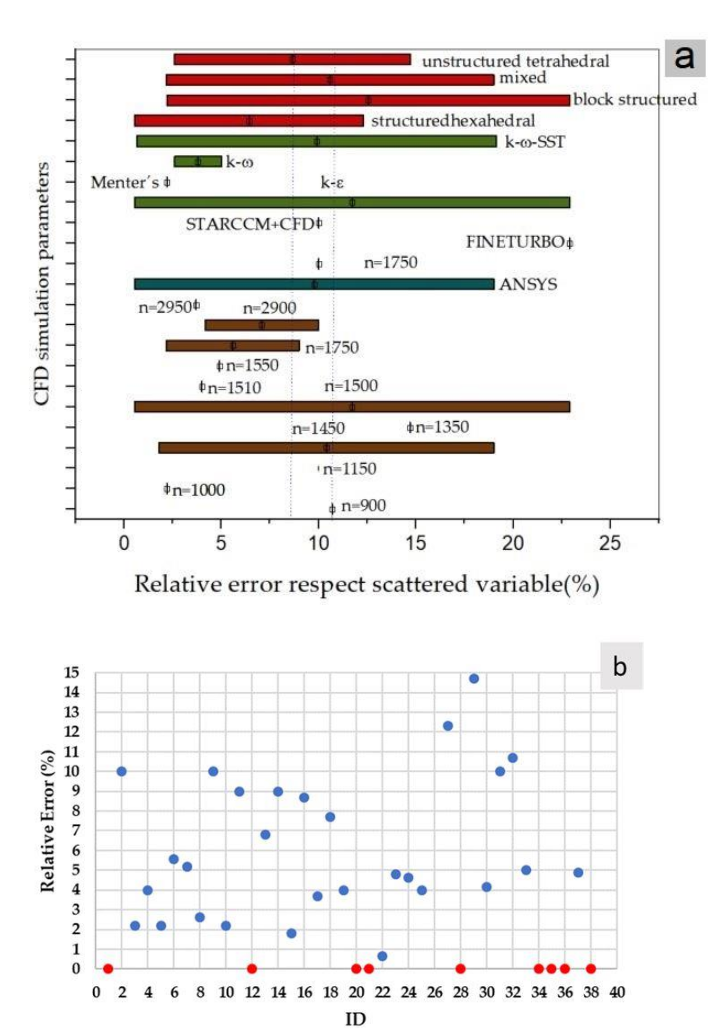
Regarding radial pumps with fixed rotation speed (a significant number of investigations and experimental tests), 40 studies were found. The boundary conditions in most studies for the input and output sections were flow rate and static pressure. The study variables, for which the relative error between numerical simulation and experimentation was obtained, were H, ψ, η, PSHAFT, and Q. Table 2 and Figure 5a show the main parameters used in numerical simulation compared to the calculated relative error.
The relative error range of 0 to 9% shows that this occurred in a range of rotation speeds from 1000 to 2950 rpm. The CFD package was used is ANSYS, and there were different closure models, i.e., k-ε,k-ω and k-ω-SST. From a mesh point of view, mixed grid unstructured and structured blocks were observed. When analyzing the error range from 9 to 11%, the rotation speeds varied from 900 to 1750 rpm as in the previous case. For the numerical simulation, it was observed that CFD packages ANSYS, StarCCM+CFD, and FloEFD were used. In this specific range, the closure models k-ε and k-ω-SST were applied, and the mesh had structured blocks, and an unsteady and structured hexahedral.
There were rotation speeds of 1450 and 1500 rpm in the range of 11–19% of relative error, meshes with structured blocks and k-ε closure model, and the FineTurbo package.
As shown in Figure 5a, the leading modelling parameters are the ANSYS package, the closure model k-ε, and mesh with structured block. From the experimental point of view, the most used rotation speed is 1500 rpm. Figure 5a shows that the relative error between experiments and numerical simulation in the research that uses Menter’s turbulence models is near to 2.5%.
Páscoa et al. [46] presented correlations to predict the head and flow of PATs based on direct operation in a centrifugal pump in reverse mode. The CFD package in this research was FLUENT and the closure turbulence model Spalart Allmaras. The number of nodes was 2,134,777 for a 3D unstructured. Yang et al. [76] compared three PAT prediction methods: a theoretical and empirical analysis, CFD, and experimental. A new formula was created to test PATs and then compared with Stepanoff and Sharma predictions. After the experimental test, the achieved results suggested that the numerical method’s agreement could predict PAT performance and BEP with acceptable accuracy. The grid was composed of hexahedral elements, and boundary conditions were static pressure at the inlet, and mass flow rate at the outlet. A simulation was carried out with ANSYS code and the closure model was k-ε. This author reported a relative error of 3.51%. The same author [47] presented an analysis of blade influence number on the performance and pressure pulsations in PATs, concluding that there is an optimal blade number for a PAT to achieve the highest efficiency, and that the pressure pulsations reduce with increasing blade number. The calculated relative error was 6.8% for efficiency. Finally, in new research [71], Yang et al. investigated how the radial gap between impeller tips and volute tongue influences the performance and the pressure pulsations of PATs using numerical simulation similar to the previous two simulations. The results showed an optimal radial related to the BEP and that, if the radial gap increased, the high-frequency pressure pulsation would be reduced. CFD Package, boundary conditions, closure turbulence, and grid are the same for the three last investigations.
Wang et al. [15] presented a numerical and experimental study on a centrifugal pump with forwarding curved blades. The principal parameters for the simulations were ANSYS Code, the k-ε turbulence model, static pressure at the inlet, the mass flow rate at the outlet and a hexahedral grid. The reported relative error for H was 10%. The same authors [36], through theoretical, practical, and numerical analysis, carried out a design of a special impeller in 2017 to use in PATs with the next conditions in the simulation: ANSYS Code, the k-ε turbulence model, the mass flow rate at the inlet, static pressure at the outlet, and a structured hexahedral grid. The calculated relative error when the efficiency was analyzed was 5.19%. Suet al. [73] focused on the internal flow-rate characteristics and attempted to reveal the periodic rules of flow-rate distribution. The main conclusions are that time average velocity diminished between the outlet and inlet section of the PAT, the net fluid passed in certain sections and others in the gap region between the rotor and the volute, and the reported relative error for η at the design point was 4.9%. In this report, CFX code and the k-ω-SST closure model were used.
Bahreini [35] designed three centrifugal pumps with CFturbo V.9 software, and their performance was analyzed by ANSYS CFX 16. The boundary condition at the inlet was mass flow while, at the outlet static frame and total pressure, the calculated relative error was 5.56%. Pérez-Sanchez and Simao [42] executed analysis for PATs installed in parallels systems. These studies have contributed to a better understanding of the PATs’ behavior in systems. Principal parameters in the simulation were FloEFD code and k-ε with all wall functions, and the mesh was generated with Solidworks. The reported relative error in this research was 10%.
Rossi et al. [41] presented a predicting model of PATs performance at design and in off-design operating conditions based on a predicting model derived from experimental data from 32 PATs and numerical simulation using CFD analysis. This analysis was executed with ANSYS CFX for a grid composed of tetrahedral wedges and hexahedral wedges and pyramids with a k-ω turbulence closure model. The reported relative error for the efficiency was 2.6%. Lal [40] carried out, with ANSYS for a grid of tetrahedral elements developed with ICEM-CFD, an analysis of cavitation and NPSHr at PATs under different operating conditions. Koswara et al. [61] carried out an analysis to optimize PATs changing the angle of impeller blade tip using ANSYS FLUENT software with the k-ε closure model and boundary conditions of pressure at the inlet and outlet of the domain. Results show that the optimal impeller blade angle is twenty-five degrees. The relative error calculated was 28.6% for p.
Figure 5b shows the relative error of the different thirty-nine case studies, which were considered in this analysis. The error relative was between 0.66 and 14.71%, except ID26, which had an error of 28.6%. The average error was 6.86% and the standard deviation was 5.45. This value enables us to use of the numerical results to develop analytical expressions and to estimate the characteristic curves for the development of the energy analysis after.
The smallest error reported for fixed rotational speed was 0.82% for discharge in the work of Wang et al. [56], who analyzed the effect of the slip factor using CFD and presented a new theoretical Head prediction method valid for low specific speed Pat (Ns < 60). The methodology showed more accuracy than other predicting models. In the validation of numerical simulation, this research presented a relative uncertainty in discharge, head, shaft power, and efficiency of PAT of ±0.82%, ±1.2%, ±1.72% and ± 2.5%, respectively.
3.3. PATs under Variable Rotational Speed
In the case of radial pumps used as PATs with variable speed rotation, the total range of rotational speeds varies from 300 to 2910 rpm and the packages used were FloEFD, PumpLinx, and ANSYS. The turbulence closure model used in all cases was k-ε. The boundary conditions at the inlet in most cases were volumetric flow and static pressures at the outlet. Different mesh types were used, both structured and unstructured, to perform the simulations. The calculation of relative error between the experiment and the value obtained in the numerical modelling for each study variable is specified in Table 3.
Frosina et al. [74] developed a new method for PATs with numerical simulation. Three centrifugal pumps with various specifics speeds were simulated in direct mode and compared with manufacturers’ data. Then, a numerical model was carried out in reverse mode and compared and validated with experimental data from a dedicated test bench from the University of Naples Federico II. There is a dispersion because some methods present high deviations, and the others are similar. The simulation was carried out with PumpLINX code for a hexagonal non-deformed grid and the k-ε turbulence closure model. The boundary condition at the inlet was volumetric flow, and in the outlet, pressure. The relative error calculated was 3.1% for p.
Pérez-Sanchez et al. [38] obtained the head drop for different rotational speeds in various machines by analyzing the behavior of pressure distribution for a PAT in a water pipe system. That study presented a CFD model with FloEFD code, the k-ε turbulence closure model with boundary conditions for the inlet and outlet of volume flow rate, and pressure recorded at the transducer. The reported relative error for H was 9%.
Pugliese [37] et al. evaluated the performance of different centrifugal PATs (48 rps): horizontal and vertical axis, single-stage and multistage, and other motor class efficiency. Principal parameters for the CFD study were ANSYS FLUENT code, structured hexahedral and unstructured tetrahedral mesh, uniform velocity distribution at the inlet and static pressure at the outlet, and the closure turbulence model k-ε. The calculated error for the efficiency was 34.62%.
Simao et al. [39] studied the effect of rotational speed and the associated velocity variations. The research aims to analyze the velocity profiles for different rotational speeds. A comparison was established between the CFD model and experimental test results to learn about hydrodynamic flow. Developing the CFD simulation with FloEFD. The boundary condition at the inlet was volume flow rate which occurred in the outlet static pressure. The closure turbulence model was k-ε with wall functions.
The analysis of the error when the machine operates under variable speed showed that the CFD simulations had a high error value, which was between 1.7 and 52.4%. Mainly, this error was upper when the analyzed variable was the efficiency. This parameter was difficult to make estimations for both analytical as well as numerical analysis, but it is crucial to obtain accurate energy studies [13]. Besides, it should be noted that hexahedral structural are preferred to tetrahedral because of their efficiency in optimizing the space in which a smaller number of cells is required to solve the geometry. Furthermore, the mesh quality generated is considered for the orthogonality and the adaptability, with the computational package that is being applied. However, due to the forms that need to be analyzed in PATs, unstructured hexahedral elements are necessary. In most analyzed cases, the use of hybrid meshes generated by the combination of tetrahedral and hexahedral cells has been visualized with good results.
In contrast, according to the research carried out, the analysis of pumps as turbines from the CFD perspective should be addressed considering the following. (i) The researcher must know the sources of error so that their respective values are in accepted ranges in engineering. It is essential to properly manage the mesh’s type and quality, numerical methods, and different models’ choices in modelling. (ii) From the meshing point of view, there is a wide variety of options, so it is necessary to adopt a mesh that suits the different geometry types. It should be noted that hexahedral structural are preferred to tetrahedral because their efficiency in optimizing the space is better. (iii) In some cases, the studies were presented to determine the mesh size suitable for carrying out the simulations to reach optimal acceptable results from computational resources and time. Other important aspects to analyze are selecting the Y+, the analysis time interval, and the time step.
4. Conclusions
There are not many studies related to numerical modelling in PATs, especially in machines with variable rotational speed. It is imperative to establish equations and laws that predict its behavior. Its proper handling would allow obtaining greater efficiency in its operation. The number of studies with free code package and with closure model k-ω-SST is minimal when their significant advantages and capabilities are considered. Finally, CFD simulation with ANSYS code and k-ε turbulence closure models presented simulations and results with an adequate relative error; this code package is currently the most used in the numerical analyses of PATs.
To solve the RANS equations, it is necessary to reformulate the Navier Stokes equations according to their average values, which results in new equations and introduces new variables. To model the turbulent flow, it is proposed to use closure models for turbulent viscosity, obtaining models of one, two, or several equations. In most turbomachinery applications, the so-called k-ε and k-ω models are applied. The main objective is to improve convergence and speed up the process. Another closure model is the k-ω-SST, which combines k-ε robustness with the accuracy of k-ω once. From a practical point of view, this latest model is the most recommended. When the investigations were carried out, the k-ε model was the most applied in most of the cases investigated.
This research shows the thirty-nine cases studies which were analyzed. This analysis shows the need to develop numerical and experimental analyses, which allow water modellers to analyze the behavior of PATs when they operate under variable rotational speed, improving the knowledge on axial machines. This analysis shows that only a few radial machines were studied under variable rotational speed numerically, and there are no studies which focus on mixed and axial machines operated as a turbine. If the energy improvement wants to reach by the installation of the micro-hydro power stations, the researchers must try to increase the knowledge database in machines, which will be able to operate when the recoverable head is low since there are many locations which show high recoverable values of energy. This opportunity has to help in the improvements of the different targets of the sustainable development goals.
Author Contributions
Conceptualization, V.H. and M.P.-S., methodology, F.P.; software, V.H.; formal analysis, F.P.; writing—original draft preparation, F.P., and M.P.-S.; writing—review and editing, M.P.-S. and P.A.L.-J.; visualization, V.H. and M.P.-S.; supervision, P.A.L.-J. All authors have read and agreed to the published version of the manuscript.
Funding
This research was financially supported by Escuela Politécnica Nacional (Project No. PIGR 20-03).
Institutional Review Board Statement
Not applicable.
Informed Consent Statement
Not applicable.
Data Availability Statement
Not applicable.
Acknowledgments
The authors gratefully acknowledge the financial support provided by Escuela Politécnica Nacional for the development of the project PIGR 20-03, PIJ17-13, PII-DIM-2019-06, and Process Simulation Laboratory of Mechanical Engineering Faculty.
Conflicts of Interest
The authors declare no conflict of interest.
Nomenclature
| H | head |
| P | power |
| p | pressure |
| Q | flow rate |
| Ns | specific speed |
| n | rotational speed |
| D | external machine diameter |
| Greek symbols | |
| ψ | |
| η | efficiency |
| ω | specific kinetic energy dissipation rate |
| ε | turbulent kinetic energy dissipation rate |
| Δ | change |
| Subscripts | |
| BEP | Best Efficient Point |
References
- Lee, S.; Pomeroy, C.; Burian, S. Setting Future Water Rates for Sustainability of a Water Distribution System. J. Water Resour. Plan. Manag. 2021, 147, 04020108. [Google Scholar] [CrossRef]
- Ahmadi, S.; Saboohi, Y.; Vakili, A. Frameworks, quantitative indicators, characters, and modeling approaches to analysis of energy system resilience: A review. Renew. Sustain. Energy Rev. 2021, 144, 110988. [Google Scholar] [CrossRef]
- Stefanizzi, M.; Capurso, T.; Balacco, G.; Binetti, M.; Camporeale, S.M.; Torresi, M. Selection, control and techno-economic feasibility of Pumps as Turbines in Water Distribution Networks. Renew. Energy 2020, 162, 1292–1306. [Google Scholar] [CrossRef]
- Ferrarese, G.; Malavasi, S. Perspectives of Water Distribution Networks with the GreenValve System. Water 2020, 12, 1579. [Google Scholar] [CrossRef]
- Renzi, M.; Rudolf, P.; Stefan, D.; Nigro, A.; Rossi, M. Installation of an axial Pump-as-Turbine (PaT) in a wastewater sewer of an oil refinery: A case study. Appl. Energy 2019, 250, 665–676. [Google Scholar] [CrossRef]
- Pérez-Sánchez, M.; Sánchez-Romero, F.J.; López-Jiménez, P.A.; Ramos, H.M. Bombas Operando Como Turbinas (PAT): Principios de Funcionamiento y Selección; Editorial UPV: Valencia, Spain, 2020. [Google Scholar]
- Binama, M.; Su, W.-T.; Li, X.-B.; Li, F.-C.; Wei, X.-Z.; An, S. Investigation on pump as turbine (PAT) technical aspects for micro hydropower schemes: A state-of-the-art review. Renew. Sustain. Energy Rev. 2017, 79, 148–179. [Google Scholar] [CrossRef]
- Rawal, S. Numerical Simulation on a Pump Operating in a turbine mode. In Proceedings of the 23rd International Pump Users Symposium, Houston, TX, USA, 5–8 March 2007. [Google Scholar]
- Nautiyal, H.; Kumar, V.; Thakur, A. CFD Analysis on Pumps Working as Turbines. Hydro Nepal J. Water Energy Environ. 1970, 6, 35–37. [Google Scholar] [CrossRef]
- Páscoa, J.; Silva, F.J.; Pinheiro, J.S.; Martins, D.J. Accuracy details in realistic CFD modeling of an industrial centrifugal pump in direct and reverse modes. J. Therm. Sci. 2010, 19, 491–499. [Google Scholar] [CrossRef]
- Carravetta, H.; Fecarotta, A.; Ramos, O. Numerical simulation on Pump as Turbine: Mesh reliability and performance concerns. In Proceedings of the 2011 International Conference on Clean Electrical Power (ICCEP), Ischia, Italy, 14–16 June 2011; pp. 169–174. [Google Scholar]
- Ramos, H.M.; Borga, A. Pumps as turbines: An unconventional solution to energy production. Urban Water 1999, 1, 261–263. [Google Scholar] [CrossRef]
- Plua, F.; Sánchez-Romero, F.-J.; Hidalgo, V.; López-Jiménez, P.; Pérez-Sánchez, M. New Expressions to Apply the Variation Operation Strategy in Engineering Tools Using Pumps Working as Turbines. Mathematics 2021, 9, 860. [Google Scholar] [CrossRef]
- Carravetta, A.; Fecarotta, O.; Del Giudice, G.; Ramos, H. Energy Recovery in Water Systems by PATs: A Comparisons among the Different Installation Schemes. Procedia Eng. 2014, 70, 275–284. [Google Scholar] [CrossRef] [Green Version]
- Wang, T.; Kong, F.; Yang, S.; Fu, Y. Numerical Study on Hydraulic Performances of Pump as Turbine with Forward-Curved Blades. In Proceedings of the Fluids Engineering Division Summer Meeting. American Society of Mechanical Engineers, Chicago, IL, USA, 3–7 August 2014. [Google Scholar]
- Fecarotta, O.; Carravetta, A.; Ramos, H.M. International Journal of Energy and Environment CFD and comparisons for a pump as turbine: Mesh reliability and performance concerns. Int. J. Energy Environ. 2011, 2, 2076–2909. [Google Scholar]
- Cando, E.; Luo, X.W.; Yu, A.; Zhu, L.; Liu, J.; Lu, L.; Hidalgo, V. Unsteady numerical analysis of the liquid-solid two-phase flow around a step using Eulerian-Lagrangian and the filter-based RANS method. J. Mech. Sci. Technol. 2017, 31, 2781–2790. [Google Scholar] [CrossRef]
- Hidalgo, V.; Escaler, X.; Valencia, E.; Peng, X.; Erazo, J.; Puga, D.; Luo, X. Scale-Adaptive Simulation of Unsteady Cavitation Around a Naca66 Hydrofoil. Appl. Sci. 2019, 9, 3696. [Google Scholar] [CrossRef] [Green Version]
- Bogdanovic-Jovanovic, J.; Milenkovic, D.; Svrkota, D.; Bogdanovic, B.; Spasić, Z.T. Pumps used as turbines power recovery, energy efficiency, CFD analysis. Therm. Sci. 2014, 18, 1029–1040. [Google Scholar] [CrossRef]
- Barrio, R.M.; Fernández, J.; Blanco, E.F.; Parrondo, J.L.; Marcos, A. Performance characteristics and internal flow patterns in a reverse-running pump–turbine. Proc. Inst. Mech. Eng. Part C J. Mech. Eng. Sci. 2011, 226, 695–708. [Google Scholar] [CrossRef]
- Vasanthakumar, P.; Arulmurugu, A.; Vinoth, R.; Gowtham, R.; Kumaresan, S.; Prasath, V. Investigation of Centrifugal Pump as Turbine: A Review Report; IJERT: Gujarat, India, 2014; Volume 3, pp. 2287–2292. [Google Scholar]
- Hidalgo, V.; Velasco, M.; Cando, E. Rotatory 3D Structured Mesh Study Using OpenFOAM to Simulate the Flow in Francis Turbine. Proceedings of MET 2021, 1–14 June 2021; pp. 1–15, Online. [Google Scholar]
- Carneiro, F.; Moura, L.; Rocha, P.C.; Lima, R.P.; Ismail, K. Application and analysis of the moving mesh algorithm AMI in a small scale HAWT: Validation with field test’s results against the frozen rotor approach. Energy 2019, 171, 819–829. [Google Scholar] [CrossRef]
- Diaz, V.H.H.; Luo, X.; Huang, R.; Cando, E. Numerical Simulation of Cavitating Flow Over 2D Hydrofoil Using OpenFOAM Adapted for Debian Operating System with LXDE Based in Kernel GNU/Linux. Am. Soc. Mech. Eng. Fluids Eng. Div. FEDSM 2014, 2. [Google Scholar] [CrossRef]
- Baker, T.J. Mesh generation: Art or science? Prog. Aerosp. Sci. 2005, 41, 29–63. [Google Scholar] [CrossRef]
- White, J.D.; Holloway, A.G.L.; Gerber, A.G. FEDSM2005-77460 Predicting Turbine Performance of High Specific Speed Pumps Using CFD. 2005. Available online: http://www.asme.org/about-asme/terms-of-use (accessed on 31 July 2021).
- Kerschberger, P.; Gehrer, A. Hydraulic development of high specific-speed pump-turbines by means of an inverse design method, numerical flow-simulation (CFD) and model testing. IOP Conf. Ser. Earth Environ. Sci. 2010, 12. [Google Scholar] [CrossRef]
- Renzi, M.; Rudolf, P.; Stefan, D.; Nigro, A.; Rossi, M. Energy recovery in oil refineries through the installation of axial Pumps-as-Turbines (PaTs) in a wastewater sewer: A case study. Energy Procedia 2019, 158, 135–141. [Google Scholar] [CrossRef]
- Kim, J.-W.; Suh, J.-W.; Choi, Y.-S.; Lee, K.-Y.; Kim, J.-H.; Kanemoto, T.; Kim, J.-H. Simultaneous efficiency improvement of pump and turbine modes for a counter-rotating type pump-turbine. Adv. Mech. Eng. 2016, 8. [Google Scholar] [CrossRef] [Green Version]
- Pienika, R.; Schenzer, D. Axial Flow Pump Used as Turbine for Hydropower Generation. In Proceedings of the III Latin American Hydro Power and Systems Meeting, Quito, Ecuador, 5–7 September 2017. [Google Scholar]
- Hlbočan, P.; Varchola, M. Numerical Simulation on a Mixed-Flow Pump Operating in A Turbine Mode. Eng. Mech. 2013, 20, 97–105. [Google Scholar]
- Capurso, T.; Stefanizzi, M.; Torresi, M.; Pascazio, G.; Caramia, G.; Camporeale, S.M.; Fortunato, B.; Bergamini, L. How to Improve the Performance Prediction of a Pump as Turbine by Considering the Slip Phenomenon. Proceedings 2018, 2, 683. [Google Scholar] [CrossRef] [Green Version]
- Capurso, T.; Stefanizzi, M.; Pascazio, G.; Ranaldo, S.; Camporeale, S.M.; Fortunato, B.; Torresi, M. Slip Factor Correction in 1-D Performance Prediction Model for PaTs. Water 2019, 11, 565. [Google Scholar] [CrossRef] [Green Version]
- Capurso, T.; Bergamini, L.; Camporeale, S.M.; Fortunato, B.; Torresi, M. CFD Analysis of the Performance of a Novel Impeller for a Double Suction Centrifugal Pump Working as a Turbine. 2019. Available online: www.euroturbo.eu (accessed on 31 July 2021).
- Bahreini, A.; Sattari, A. Numerical and Economic Study of Performance of Centrifugal Pump as Turbine. J. Comput. Appl. Mech. 2017, 48, 151–160. [Google Scholar] [CrossRef]
- Wang, T.; Wang, C.; Kong, F.; Gou, Q.; Yang, S. Theoretical, experimental, and numerical study of special impeller used in turbine mode of centrifugal pump as turbine. Energy 2017, 130, 473–485. [Google Scholar] [CrossRef]
- Pugliese, F.; De Paola, F.; Fontana, N.; Giugni, M.; Marini, G.; Francos, J.F. Experimental and numerical investigation of centrifugal Pumps as Turbines. In Proceedings of the 10th International Conference on Energy Efficiency in Motor Driven System, Rome, Italy, 6–8 September 2017. [Google Scholar]
- Pérez-Sánchez, M.; Simão, M.; López-Jiménez, P.A.; Ramos, H.M. CFD Analyses and Experiments in a PAT Modeling: Pressure Variation and System Efficiency. Fluids 2017, 2, 51. [Google Scholar] [CrossRef] [Green Version]
- Simão, M.; Pérez-Sánchez, M.; Carravetta, A.; López-Jiménez, P.; Ramos, H.M. Velocities in a Centrifugal PAT Operation: Experiments and CFD Analyses. Fluids 2017, 3, 3. [Google Scholar] [CrossRef] [Green Version]
- Lal, B.; Deshmukh, T.S. Performance Analysis of Centrifugal Pump at Different Operating Mode. Smart Moves J. Ijoscience 2018, 4, 8. [Google Scholar] [CrossRef] [Green Version]
- Rossi, M.; Nigro, A.; Renzi, M. A predicting model of PaTs’ performance in off-design operating conditions. Energy Procedia 2019, 158, 123–128. [Google Scholar] [CrossRef]
- Simão, M.; Pérez-Sánchez, M.; Carravetta, A.; Ramos, H.M. Flow Conditions for PATs Operating in Parallel: Experimental and Numerical Analyses. Energies 2019, 12, 901. [Google Scholar] [CrossRef] [Green Version]
- Derakhshan, S.; Nourbakhsh, A. Theoretical, numerical and experimental investigation of centrifugal pumps in reverse operation. Exp. Therm. Fluid Sci. 2008, 32, 1620–1627. [Google Scholar] [CrossRef]
- Sedlář, M.; Jiříšoukal, J.J.; Komárek, M. CFD Analysis of Middle Stage of Multistage Pump Operating in Turbine Regime. Eng. Mech. 2009, 16, 413–421. [Google Scholar]
- Fernández, J.; Barrio, R.; Blanco, E.; Parrondo, J.L.; Marcos, A. Numerical investigation of a centrifugal pump running in reverse mode. Proc. Inst. Mech. Eng. Part A J. Power Energy 2009, 224, 373–381. [Google Scholar] [CrossRef]
- Páscoa, J.C.; Silva, F.J.; Pinheiro, J.S.; Martins, D.J. A New Approach for Predicting PAT-Pumps Operating Point from Direct Pumping Mode Characteristics. J. Sci. Ind. Res. 2012, 71, 144–148. [Google Scholar]
- Yang, S.-S.; Kong, F.-Y.; Qu, X.-Y.; Jiang, W.-M. Influence of Blade Number on the Performance and Pressure Pulsations in a Pump Used as a Turbine. J. Fluids Eng. 2012, 134, 124503. [Google Scholar] [CrossRef]
- Maleki, A.; Ghorani, M.M.; Haghighi, M.H.S.; Riasi, A. Numerical study on the effect of viscosity on a multistage pump running in reverse mode. Renew. Energy 2020, 150, 234–254. [Google Scholar] [CrossRef]
- Fernández, J.; Blanco, E.; Parrondo, J.L.; Stickland, M.T.; Scanlon, T.J. Performance of a centrifugal pump running in inverse mode. Proc. Inst. Mech. Eng. Part A J. Power Energy 2004, 218, 265–271. [Google Scholar] [CrossRef] [Green Version]
- Fengxia, S.; Junhu, Y.; Senchun, M.; Xiaohui, W. Investigation on the power loss and radial force characteristics of pump as turbine under gas–liquid two-phase condition. Adv. Mech. Eng. 2019, 11. [Google Scholar] [CrossRef]
- Wang, X.; Yang, J.; Xia, Z.; Hao, Y.; Cheng, X. Effect of Velocity Slip on Head Prediction for Centrifugal Pumps as Turbines. Math. Probl. Eng. 2019, 2019, 1–10. [Google Scholar] [CrossRef] [Green Version]
- Miao, S.C.; Yang, J.; Shi, F.; Wang, X.; Shi, G. Research on energy conversion characteristic of pump as turbine. Adv. Mech. Eng. 2018, 10. [Google Scholar] [CrossRef] [Green Version]
- Shi, H.X.; Chai, L.P.; Su, X.Z.; Jaini, R. Performance Optimization of Energy Recovery Device Based on PAT with Guide Vane. Int. J. Simul. Model. 2018, 17, 472–484. [Google Scholar] [CrossRef]
- Yang, S.-S.; Wang, C.; Chen, K.; Yuan, X. Research on Blade Thickness Influencing Pump as Turbine. Adv. Mech. Eng. 2014, 6. [Google Scholar] [CrossRef]
- Shi, F.; Yang, J.; Wang, X. Analysis on the effect of variable guide vane numbers on the performance of pump as turbine. Adv. Mech. Eng. 2018, 10. [Google Scholar] [CrossRef]
- Miao, S.C.; Yang, J.-H.; Shi, G.-T.; Wang, T.-T. Blade profile optimization of pump as turbine. Adv. Mech. Eng. 2015, 7. [Google Scholar] [CrossRef] [Green Version]
- Sun, Y.; Zuo, Z.; Liu, S.; Liu, J.; Wu, Y. Distribution of Pressure Fluctuations in a Prototype Pump Turbine at Pump Mode. Adv. Mech. Eng. 2014, 6. [Google Scholar] [CrossRef]
- Schleicher, W.; Oztekin, A. Hydraulic design and optimization of a modular pump-turbine runner. Energy Convers. Manag. 2015, 93, 388–398. [Google Scholar] [CrossRef] [Green Version]
- Natanasabapathi, S.R.; Kshirsagar, J.T. Pump as Turbine—An Experience with CFX-5.6; Kirloskar Brothers Ltd.: Pune, India, 2004. [Google Scholar]
- Barrio, R.; Fernández, J.; Parrondo, J.; Blanco, E. Performance Prediction for a Centrifugal Pump Working in Direct and Reverse Mode Using Computational Fluid Dynamics. Renew. Energy Power Qual. J. 2010, 1, 1429–1433. [Google Scholar] [CrossRef]
- Koswara, E.; Budiman, H.; Fikri, N. Flow Analysis in Pump as Turbines (PATs) Using Ansys Fluent Software. 2020. Available online: http://jurnal.umj.ac.id/index.php/sintek (accessed on 31 July 2021).
- Yang, S.S.; Kong, F.Y.; Jiang, W.M.; Qu, X.Y. Research on rotational speed to the influence of pump as turbine. IOP Conf. Ser. Earth Environ. Sci. 2012, 15. [Google Scholar] [CrossRef]
- Rosa, H.M.P.; Emerick, B.S. Revista Brasileira de Engenharia Agrícola e Ambiental CFD simulation on centrifugal pump impeller with splitter blades Simulação CFD em rotor de bomba centrifuga com pás intermediárias. Eng. Agrícola Ambient. 2020, 24, 3–7. [Google Scholar]
- Ismail, M.A.; Othman, A.K.; Zen, H. Numerical Investigation of Rotational Speed on Pump as Turbine for Microhydro Applications. Appl. Mech. Mater. 2016, 833, 11–18. [Google Scholar] [CrossRef]
- Liu, M.; Tan, L.; Cao, S. Theoretical model of energy performance prediction and BEP determination for centrifugal pump as turbine. Energy 2019, 172, 712–732. [Google Scholar] [CrossRef]
- Aidhen, A.S.; Malik, S.; Kishanrao, C.D. Theoretical, Numerical and Experimental Research of Single Stage, Radial Discharge Centrifugal Pump Operating in Turbine Mode. Int. J. Innov. Technol. Explor. Eng. 2019, 8, 1265–1270. [Google Scholar] [CrossRef]
- Du, J.; Yang, H.; Shen, Z.; Chen, J. Micro hydro power generation from water supply system in high rise buildings using pump as turbines. Energy 2017, 137, 431–440. [Google Scholar] [CrossRef]
- Rossi, M.; Nigro, A.; Renzi, M. Experimental and numerical assessment of a methodology for performance prediction of Pumps-as-Turbines (PaTs) operating in off-design conditions. Appl. Energy 2019, 248, 555–566. [Google Scholar] [CrossRef]
- Arulmurugu, P.V.; Pandian, A. Numerical investigation of centrifugal pump as turbine. Adv. Appl. Fluid Mech. 2015, 7, 147–163. [Google Scholar] [CrossRef]
- Baburaj, E.; Sivaprakasam, R.; Manikandan, C.; Sudha, K. CFD Analysis of Pump as Turbine for Micro-Hydro Schemes. 2013. Available online: www.ijirset.com (accessed on 31 July 2021).
- Yang, S.-S.; Liu, H.-L.; Kong, F.-Y.; Xia, B.; Tan, L.-W. Effects of the Radial Gap Between Impeller Tips and Volute Tongue Influencing the Performance and Pressure Pulsations of Pump as Turbine. J. Fluids Eng. 2014, 136, 054501. [Google Scholar] [CrossRef]
- Ismail, M.A.; Othman, A.K.; Zen, H. Numerical Simulation on End Suction Centrifugal Pump Running in Inverse Flow for Microhydro Applications. Appl. Mech. Mater. 2015, 773–774, 358–362. [Google Scholar] [CrossRef] [Green Version]
- Su, X.; Huang, S.; Zhang, X.; Yang, S. Numerical research on unsteady flow rate characteristics of pump as turbine. Renew. Energy 2016, 94, 488–495. [Google Scholar] [CrossRef]
- Frosina, E.; Buono, D.; Senatore, A. A Performance Prediction Method for Pumps as Turbines (PAT) Using a Computational Fluid Dynamics (CFD) Modeling Approach. Energies 2017, 10, 103. [Google Scholar] [CrossRef] [Green Version]
- Rosado, L.E.C.; López-Jiménez, P.A.; Sánchez-Romero, F.-J.; Fuertes, P.C.; Pérez-Sánchez, M. Applied Strategy to Characterize the Energy Improvement Using PATs in a Water Supply System. Water 2020, 12, 1818. [Google Scholar] [CrossRef]
- Yang, S.-S.; Derakhshan, S.; Kong, F.-Y. Theoretical, numerical and experimental prediction of pump as turbine performance. Renew. Energy 2012, 48, 507–513. [Google Scholar] [CrossRef]
Figure 1.
(a) Grid mesh for a Francis turbine; (b) AMI interfaces.

Figure 2.
Methodology Flowchart.

Figure 3.
(a) CFD packages used in the published simulation; (b) Closure turbulence models, (c) Used mesh.
Figure 3.
(a) CFD packages used in the published simulation; (b) Closure turbulence models, (c) Used mesh.

Figure 4.
Consulted researches.

Figure 5.
(a) Error analysis as a function of CFD parameters; (b) Error analysis as a function of relative error and ID (red points indicate the data is not available in the research or it cannot be calculated).
Figure 5.
(a) Error analysis as a function of CFD parameters; (b) Error analysis as a function of relative error and ID (red points indicate the data is not available in the research or it cannot be calculated).


Table 1.
Consulted researches.
| Type of Machine | Published Research | Consulted References |
|---|---|---|
| Axial | 7 | [5,11,26,27,28,29,30] |
| Mixed | 5 | [8,31,32,33,34] |
| Radial | 44 | [10,15,19,20,28,35,36,37,38,39,40,41,42,43,44,45,46,47,48,49,50,51,52,53,54,55,56,57,58,59,60,61,62,63,64,65,66,67,68,69,70,71,72,73,74] |
Table 2.
Boundary conditions, study variable and reported/calculated error in radial pumps with fixed speed rotation.
Table 2.
Boundary conditions, study variable and reported/calculated error in radial pumps with fixed speed rotation.
| ID | Reference | Boundary Conditions | Study-Variable | Relative Max Error (%) | |
|---|---|---|---|---|---|
| Inlet | Outlet | ||||
| 1 | [10] | stagnation pressure | static pressure | - | - |
| 2 | [15] | static pressure | mass flow | H | 10 |
| 3 | [20] | constant total pressure | constant static pressure | η | 2.18 |
| 4 | [19] | - | - | H | 4 |
| 5 | [20] | constant total pressure | constant static pressure | η | 2.18 |
| 6 | [35] | mass flow | static frame total pressure | H | 5.56 |
| 7 | [36] | mass flow | static pressure | η | 5.19 |
| 8 | [41] | volume flow rate | average static pressure | η | 2.6 |
| 9 | [42] | flow rate | static pressure | Q | 10 |
| 10 | [44] | - | - | H | 2.2 |
| 11 | [45] | uniform velocity distribution | constant static pressure | H | 9.0 |
| 12 | [46] | mass flow | static pressure | H, η | - |
| 13 | [47] | static pressure | mass flow | η | 6.8 |
| 14 | [49] | uniform velocity | constant static pressure | H | 9 |
| 15 | [51] | - | - | Q | 0.82 |
| 16 | [52] | velocity inlet | static pressure | η | 8.70 |
| 17 | [53] | total pressure | mass flow | H | 3.70 |
| 18 | [54] | static pressure | mass flow | η | 7.69 |
| 19 | [55] | velocity inlet | pressure outlet | η | 3.99 |
| 20 | [56] | velocity inlet | pressure outlet | - | - |
| 21 | [69] | total pressure | environmental pressure | - | - |
| 22 | [58] | mass flow | - | - | - |
| 23 | [50] | mass flow | - | H | 4.81 |
| 24 | [59] | pressure | mass flow | η | 4.64 |
| 25 | [60] | constant total pressure | variable static | ψ | 4.00 |
| 26 | [61] | pressure inlet | pressure outlet | p | 28.60 |
| 27 | [62] | static pressure | mass flow | P | 12.31 |
| 28 | [63] | static pressure | mass flow | - | - |
| 29 | [64] | mass flow | static pressure | P | 14.71 |
| 30 | [65] | static pressure | mass flow | η | 4.17 |
| 31 | [66] | - | - | H | 10.00 |
| 32 | [67] | velocity | static pressure | H | 10.70 |
| 33 | [68] | volumetric flow rate | average static pressure | ψ | 5.00 |
| 34 | [70] | enviromental pressure 1bar | mass flow | - | - |
| 35 | [71] | static pressure | mass flow | - | - |
| 36 | [72] | mass flow | static pressure | ψ | - |
| 37 | [73] | total pressure | flow rate | η,ψ (design point) | 4.9 |
| 38 | [43] | mass flow, velocity direction, turbulence kinetic energy k and turbulent dissipation ε | static pressure | ψ | 22.9 |
| 38 | [76] | static pressure | mass flow | PSHAFT | 3.51 |
Table 3.
Radial pumps analysis with variable speed rotation.
| n | Package | Numerical Simulation | Boundary Condition | Error Calculation | Reference | |||
|---|---|---|---|---|---|---|---|---|
| rpm | Closure M | Grid | Inlet | Outlet | Variable-Study | Relativemax Error (%) | ||
| 300–2200 | PumpLinx | k-ε | hexagonal not deformed cells | flow | pressure | p | 3.10 | [74] |
| 520–1500 | FloEFD | k-ε | structured hexaedral | flow rate | pressure | ΔH, η | (1,7–44,48), (0–52,4) | [39] |
| 810–1500 | FloEFD | k-ε with wall functions | structured hexahedral | flow rate | static pressure | H | 9 | [38] |
| 1500–2910 | ANSYS-FLUENT | k-ε | structured hexahedral/unstructured tetrahedral | Unif. velocity | static pressure | η | 34.62 | [37] |
Publisher’s Note: MDPI stays neutral with regard to jurisdictional claims in published maps and institutional affiliations. |
© 2021 by the authors. Licensee MDPI, Basel, Switzerland. This article is an open access article distributed under the terms and conditions of the Creative Commons Attribution (CC BY) license (https://creativecommons.org/licenses/by/4.0/).
Share and Cite
MDPI and ACS Style
Plua, F.; Hidalgo, V.; López-Jiménez, P.A.; Pérez-Sánchez, M. Analysis of Applicability of CFD Numerical Studies Applied to Problem When Pump Working as Turbine. Water 2021, 13, 2134. https://doi.org/10.3390/w13152134
AMA Style
Plua F, Hidalgo V, López-Jiménez PA, Pérez-Sánchez M. Analysis of Applicability of CFD Numerical Studies Applied to Problem When Pump Working as Turbine. Water. 2021; 13(15):2134. https://doi.org/10.3390/w13152134
Chicago/Turabian StylePlua, Frank, Victor Hidalgo, P. Amparo López-Jiménez, and Modesto Pérez-Sánchez. 2021. "Analysis of Applicability of CFD Numerical Studies Applied to Problem When Pump Working as Turbine" Water 13, no. 15: 2134. https://doi.org/10.3390/w13152134
Note that from the first issue of 2016, this journal uses article numbers instead of page numbers. See further details here.