1. Introduction
The formation of a hydraulic jump in stilling basins is frequently used as an energy dissipation system to reduce the scour downstream of hydraulic structures [
1]. Methods for enhancing the energy dissipation, and thus shortening the length of the basin, have been proposed in many studies. These methods typically include the use of appurtenances, such as baffle piers, end sills, blocks, or roughness elements [
2,
3,
4,
5,
6,
7,
8,
9,
10], while few studies also examined the possibility of using bed water jets as a means of dissipation. This last method can be a cost-effective solution, considering that water jets can be generated by deriving the flow from the upstream storage of the hydraulic structure using a system of pipes and by exploiting the head difference to the stilling basin. In particular, Tharp [
11] first studied the effectiveness of injecting submerged water jets on the classical hydraulic jump. Mele and Viti [
12] analyzed the effect of a secondary recirculating current caused by the difference of pressure head in two sections connected through a false floor, reporting substantial modifications in the flow patterns. France [
13] used a similar arrangement to generate inclined counterflow jets in the stilling basin, describing their ability in reducing the tailwater depth required to stabilize the hydraulic jump, especially when the jet inclination generates a stronger counterflow component. These results have been recently confirmed by Alghwail et al. [
14], who studied the effect of a single counterflow jet originating from a submerged orifice, by carrying out experiments with varying inclination, width, and position of the opening. They indicated optimal behavior when the jet is inclined at 45° and when it is located in the jump area, approaching the upstream section. Varol et al. [
15] investigated the effect of water jets on the characteristics of hydraulic jumps, in terms of flow structure, roller length, water surface profiles, and energy losses, while Helal et al. [
16] confirmed the performance of this kind of dissipation device in improving the efficiency of submerged hydraulic jumps.
Still, practical situations exist where the downstream tailwater depth is very low and the classical jump cannot be created, even with the use of dissipation elements. In similar conditions, channel expansion can be a suitable solution [
17], which, however, is prone to the possible occurrence of spatial hydraulic jumps (i.e., S-jump), characterized by unstable and asymmetric flows for specific narrow ranges of tailwater levels, for which a slight variation in the boundary condition can result in strong modifications of the cross-sectional velocity distribution and local velocity maxima [
18,
19,
20,
21,
22,
23,
24,
25]. Previous studies have demonstrated that these undesirable phenomena may be prevented or limited by inserting in the stilling basin solid sills [
20,
26], roughness elements [
27], or cross-beam devices [
24,
25].
In the present study, the use of counterflow jets (i.e., opposed to the main direction of the approaching flow), generated by a transversal pipe fed by the same upstream storage supplying the main flow, is considered as an alternative dissipation system to stabilize the spatial hydraulic jump and to reduce the risk of flow asymmetry and instability phenomena in abruptly expanding channels. From a practical point of view, the device provides a double benefit, by adding the momentum of the jets to the downstream force and, at the same time, reducing the upstream flow rate, as if the return period of the flood was lower.
Several configurations, under three inflowing conditions, were first investigated to explore the system’s functioning and its performance in establishing near-bed uniform flow conditions in the tailwater channel. Some of the best-performing configurations were then selected to be tested under more severe boundary conditions, providing further insights on the dissipative mechanism and on the flow field induced by the device downstream from it.
2. Materials and Methods
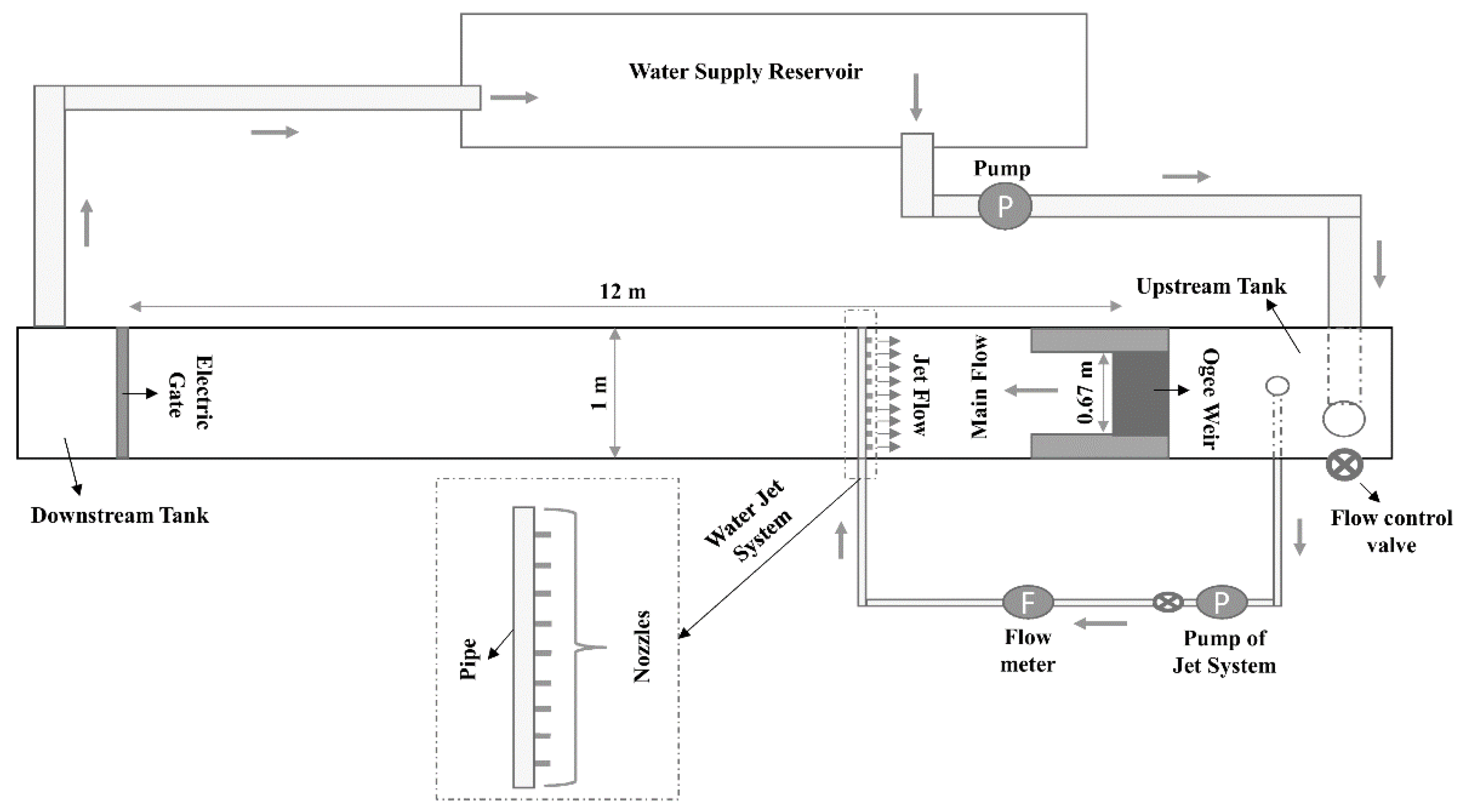
The experiments were carried out in a flume in the hydraulic laboratory of the Faculty of Water Science Engineering at the Shahid Chamran University of Ahvaz, Iran. The flume consisted of a storage tank (1 m wide and 2.4 m long), an ogee weir (with a height of 0.6 m and a width of 0.67 m), and a rectangular horizontal channel (12 m long, 1 m wide, and 0.87 m deep). Two plexiglass walls were installed at the toe of the weir on both sides of the channel to create a narrow section (0.6 m long and 0.67 m wide), i.e., an abrupt expansion (with an expansion ratio of
b/B = 0.67 m, where
b and
B are, respectively, the upstream and the downstream width). A vertical sluice gate was installed in the terminal part of the flume to control the tailwater depth (
Figure 1).
The first phase of the experiments was then aimed at defining these reference tailwater conditions to be used for the subsequent testing of the device. By adjusting the terminal gate, this phase then consisted of the identification of the boundary downstream water levels leading to the formation of S-jumps for the considered inflowing discharges of 56.3, 44.5, and 36.9 L/s; selected tailwater depths were equal to 0.179, 0.144, and 0.109 m for the tested Froude number Fr = 7.4, 8.7, and 9.5 (Fr = v1/(g·h1)0.5, where v1 and h1 are the velocity and the depth of the approaching flow and g is the gravitational acceleration).
Under these reference conditions, measurements of the near-bed longitudinal flow velocity were carried out with a micro-propeller (Nixon Streamflow 403–404, characterized by an accuracy of ±1.5% of true velocity) at 9 equidistant points (i.e., with a spacing of 0.1 m) on each of the 8 representative cross-sections located 0.25, 0.50, 0.75, 1.0, 1.25, 1.5, 2.5, and 8 m downstream from the abrupt expansion. The measurements were performed at a constant height of 0.5 cm from the channel bed (i.e., the minimum height achievable with the instrumentation used), for a time duration of 30 s; the time-averaged velocity was then considered for each registered time series. Water depth was also surveyed within the defined measuring grid, using a point gauge with an accuracy of ±1 mm.
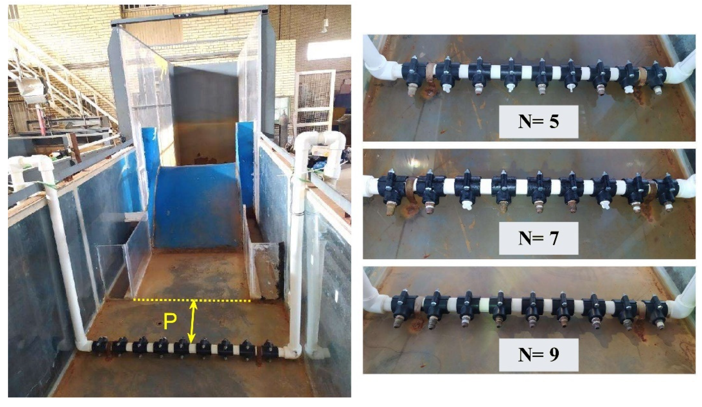
In the second phase of the experiments, the dissipator was installed in the stilling basin. The investigated device is a water jet injection system, consisting of a 3.17 cm diameter PVC pipe orthogonally crossing the flume, with nozzles of 0.95 cm in diameter and equal spacing of 8.5 cm (
Figure 2). The PVC pipe was connected to the upstream tank and the flow rate of the jets was regulated by a pump and measured with an electromagnetic flowmeter. In this experimental phase, the inlet discharge was increased compared to the one in the reference conditions, in order to keep the upstream
Fr values constant while also supplying the jets.
A total of 54 different configurations of the device were tested, by changing the following hydraulic and geometric parameters:
Froude number of the approaching flow (Fr) and the corresponding reference tailwater levels identified in the first phase (hs);
Distance of the jet system from the expansion section in the flume (P): 0.4, 0.6, and 0.8 m;
Jet density, i.e., number of open nozzles in water jet injection system (
N): 5, 7, and 9 (
Figure 2);
Jet flow rate (Qj): 8.1 and 7.2 L/s.
In the experimental runs with the installed device, the measurements of flow velocity and depth were executed analogously to the first phase, but only in two control sections, located 0.5 m downstream from the dissipator, and at the terminal section at 8 m from the expansion. The position of the first measurement section, which can be considered a suitable end section for the stilling basin (i.e., downstream from the region where the main dissipative phenomena take place), was identified in preliminary tests in order to ensure an unbiased comparison of the devices.
The performances of the different configurations were evaluated by comparing the near-bed flow features observed downstream from the device to the ones of the original S-jump conditions. For the characterization of the flow uniformity in quantitative terms, Scorzini et al. [
24] introduced the parameter
βb, which is a modified version of the Boussinesq momentum correction coefficient for near-bed velocity:
where
B is the channel width,
vb(
x) is the near-bed longitudinal velocity across the section, and
vmb is the average value of
vb(
x).
The product βb·vmb2 provides information on the dynamic force of the flow (per unit height at the measurement depth) and then on its scouring potential, which is important when assessing the effectiveness of a stilling basin downstream from a hydraulic structure. βb and βb·vmb2 were computed for both the reference and the 54 “with device” conditions, thus allowing for a comparative analysis of the performances of the different tested configurations of the dissipator.
In addition, a global assessment of the dissipated energy between the reservoir (
E1) and the control section at 0.5 m downstream from the device (
E2) was carried out based on the experimental measurements. In calculating the efficiency (Δ
E =
(E1 − E2)/E1), the kinetic energy correction coefficient was neglected for the upstream section (1), under the hypothesis of uniform velocity distribution, while for the downstream one (2), the near-bed coefficient
αb was used in lieu of the global Coriolis value (
α), assuming it as representative of the whole cross-section.
αb was computed similarly to
βb based on the longitudinal velocities measured at the elevation of 0.5 cm from the channel bed:
Based on the results of this analysis, three of the best-performing geometries were selected to be tested under more severe tailwater levels (75, 80, and 90% of
hs) in order to investigate the effectiveness of the counterflow jets under a large spectrum of boundary conditions, as may occur in the actual operating conditions of a hydraulic structure. In this phase, 3D velocity measurements (with an electromagnetic velocity meter (JFE Advantech Co. ACM3-RS 3 axis, with an accuracy of ±2% of true velocity)) in four different cross-sections, located 0.25, 0.5, 1, and 2 m downstream from the dissipator, allowed a more detailed reconstruction of the flow velocity field in the tailwater channel, with the possibility of calculating the global Coriolis and Boussinesq correction coefficients of the flow,
α and
β [
1,
28]:
where
A is the total cross-sectional flow area,
v(
x,z) is the longitudinal velocity over the whole cross-sectional profile, and
vm is the mean flow velocity.
This analysis also allowed the verification of the representativeness of the bed coefficients, αb and βb, for describing the uniformity of the flow features instead of using the global coefficients, α and β. Indeed, although both the parameters (α and αb; β and βb) are flow uniformity coefficients, the ones denoted with lowercase “b” consider only the velocity field in the proximity of the channel bed instead of that for the whole cross-sectional area.
Moreover, in order to obtain more information on the dissipative mechanism in the stilling basin equipped with the bed counterflow jets, for the selected configurations, pressure transducers (Hoggler Hot Series), measuring the dynamic pressure at the basin floor, were installed in the centerline of the flume at four points, located both downstream and upstream from the jets (0.25 and 0.75 m in the first case, and 0.25 and 0.85 m in the second case). For each pressure tap, data were sampled at a frequency of 200 Hz over a time duration of 60 s. Due to the turbulent flow characteristics developing within the basin, the pressure regime can be analyzed as a stochastic phenomenon. Therefore, as proposed by Toso and Bowers [
29], pressure fluctuations were treated as random variables, which can be characterized by statistical parameters, such as mean, standard deviation, skewness, and kurtosis. In particular, the pressure coefficient
Cp′ [
29], which compares the standard deviation of the pressure head
σ with the inflow velocity head, was calculated from the experimental measurements:
where
v1 is the approaching flow velocity and
g is the gravitational acceleration.
Analogous coefficients for the mean pressure head
Pm and both negative and positive fluctuations from the mean, ∆
P+ and ∆
P−, were expressed as well [
29]:
3. Results and Discussion
The reproduced reference conditions are the ones typical of the spatial hydraulic jump, with the main flow concentrated at one side of the cross-section, high local velocities extending over the whole tailwater channel, and a reverse flow area on the opposite side. For all the tested hydraulic conditions, the flow reached the end of the channel without completing the transition to subcritical flow. This is clearly visible in
Figure 3, where
βb values are considerably greater than unity in all the measurement sections, reaching the maximum values at 2.5 m downstream from the expansion section, and still being over 2 at the end of the flume. The comparison of
βb and
βb·vmb2 obtained with the installed device to the ones shown in
Figure 3 then provides direct information on the effectiveness of the counterflow jets in stabilizing the hydraulic jump occurring in the expanding channel.
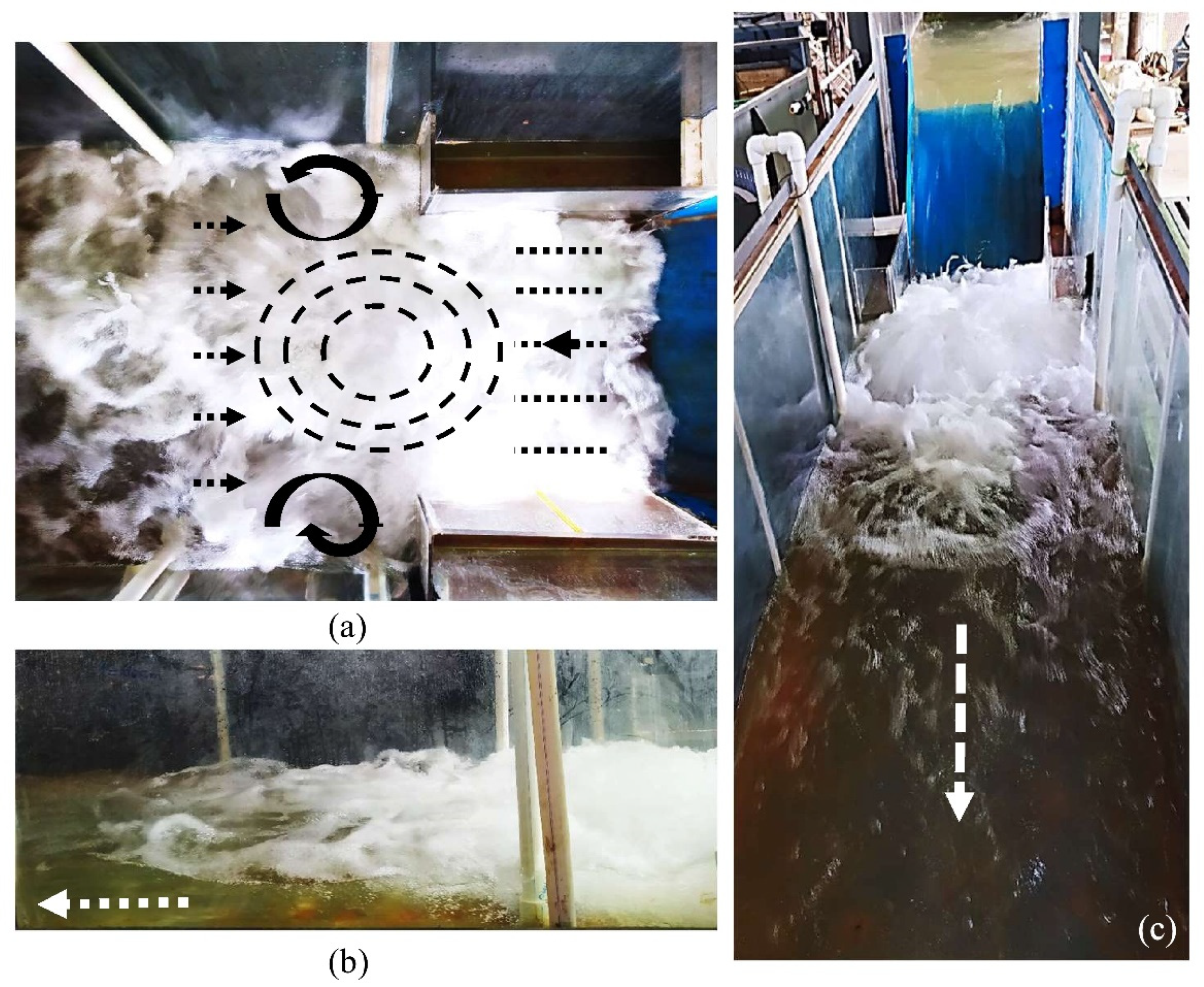
Figure 4 shows the flow patterns in the stilling basin equipped with the jet injection system. The interaction between the supercritical flow issuing from the narrow section and the counterflow jets results in a high-turbulence zone in the middle of the expansion section, with a higher flow depth and strong air entrainment, pushing away the top part of the flow and leading to local radial vortices, somewhat similar to many classical hydraulic jumps. The turbulence is almost entirely concentrated in the area upstream from the jets, resulting in quite regular subcritical flow conditions within a short distance downstream from the device, i.e., allowing for stilling basins of limited length.
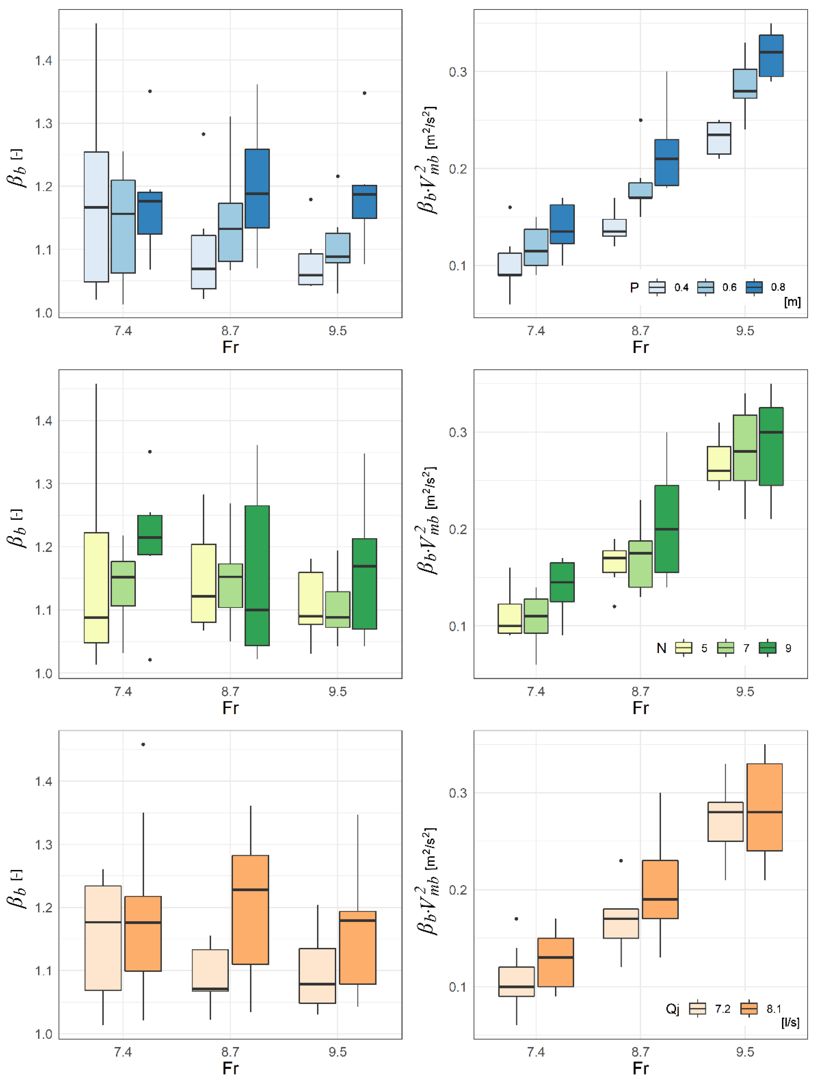
This qualitative evidence is highlighted in quantitative terms in
Figure 5, which summarizes the values of
βb and
βb·vmb2 registered for all the experimental runs at the measurement section located 0.5 m downstream from the dissipator (i.e., 0.9, 1.1, and 1.3 m from the abrupt expansion for
P equal to 0.4, 0.6, and 0.8 m, respectively). In this section, the flow depth was always slightly higher than the one at the end of the flume (as expected in a horizontal channel in subcritical condition) and the results for
βb (ranging from 1.01 to 1.46, with a mean of 1.15) and
βb·vmb2 (the maximum registered value was equal to 0.35 m
2/s
2) reveal a good effectiveness of the system in improving the flow features in the tailwater channel, allowing the transition to subcritical flow in a stilling basin of limited length, even for the worst-performing configurations. At the end of the flume (i.e., at the measurement section at 8 m from the expansion), the flow was found to be always uniform, with
βb values constantly smaller than 1.03.
It should be noted that these runs were carried out under the same water levels defined in the reference conditions (
hs), resulting in a higher downstream
Fr, with reduced jump stabilization capability in the applications with flow-dependent boundary conditions. In addition,
Figure 5 indicates that the distance of the device from the expansion section (
P) is an influencing factor for the performance of the system, as demonstrated by the slightly higher values of
βb and
βb·vmb2 found in the tests with the larger values of
P.
An explanation for this behavior can be deduced from the observation of
Figure S1 (in the Supplemental Materials), which shows the flow patterns in the stilling basin for two configurations of the device that differ only in the value of
P (0.4 versus 0.8 m). It can be seen that, in the first case, the high-pressure region invades a larger portion of the narrow channel and the main flow approaches the jets with a higher velocity. Since the variation of the kinetic energy flux associated with the collision of the jets is a function of the cube of the velocity [
30], this mechanism implies a higher rate of conversion into pressure head and/or energy dissipation for a given discharge, which could then explain the slightly worse performances of the devices with
P = 0.8 m.
Figure 5 also shows that the bed velocity
vmb has been found to increase with the jet density (i.e., higher number of open nozzles,
N), suggesting that the flow tends to be diverted towards the free surface when the jets are less uniformly distributed across the channel. This phenomenon could be a consequence of the increase in total momentum and kinetic energy per unit of
Qj associated with a smaller number of nozzles (i.e., higher velocity of the jets), resulting in a higher local pressure upstream of the device. Regarding the influence of the jet discharge
Qj, this was found to negatively affect
βb, except for
Fr = 7.4, while the values of
βb·vmb2 were not surprisingly higher for increasing
Qj, because of the larger flow rate under the same downstream boundary condition.
Moreover, as expected under controlled tailwater conditions, the energy dissipation was basically a function of Fr, with almost no influence from the geometric parameters of the device, registering a reduction in the flow energy (ΔE) of about 74, 79, and 82% for Fr equal to 7.4, 8.7, and 9.5, respectively.
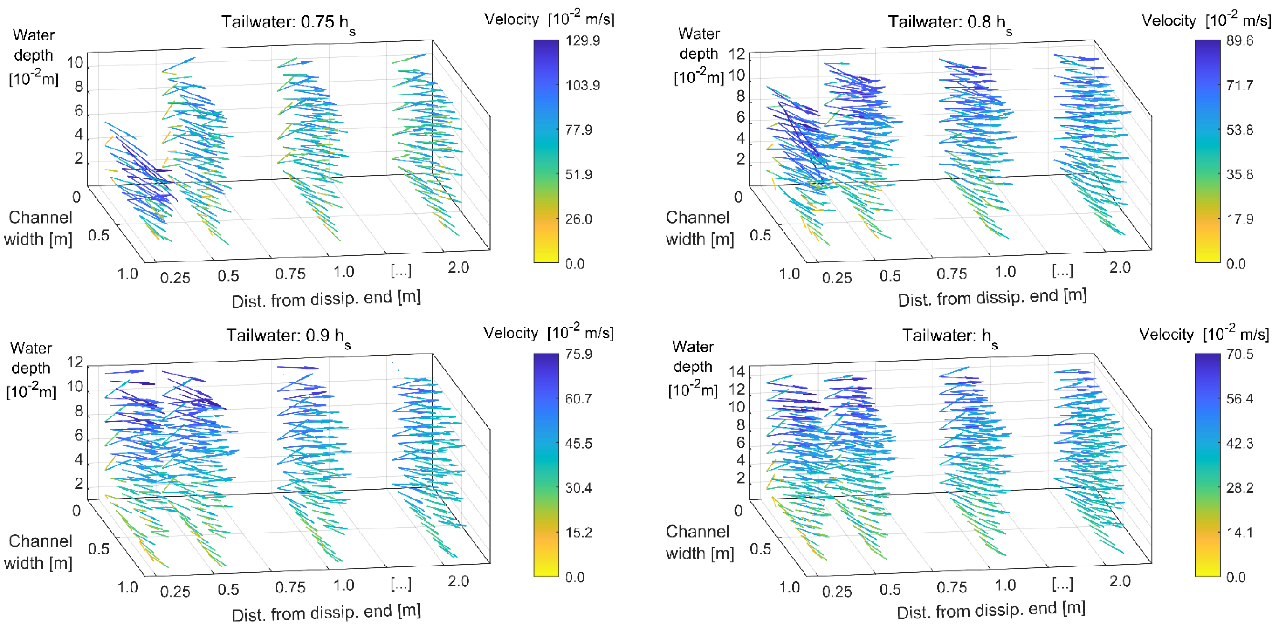
In the second phase of the analysis, some of the most effective configurations were selected for a detailed investigation aimed at testing their performance under more severe tailwater conditions and better describing the flow features in the tailwater channel. Given the small variability observed in the behavior of the tested geometries, hereinafter, we report for illustrative purposes the results related to the following configurations (Fr = 7.4 in all runs):
Qj = 7.2 L/s, N = 7, P = 0.4 m;
Qj = 8.1 L/s, N = 9, P = 0.4 m;
Qj = 7.2 L/s, N = 5, P = 0.6 m.
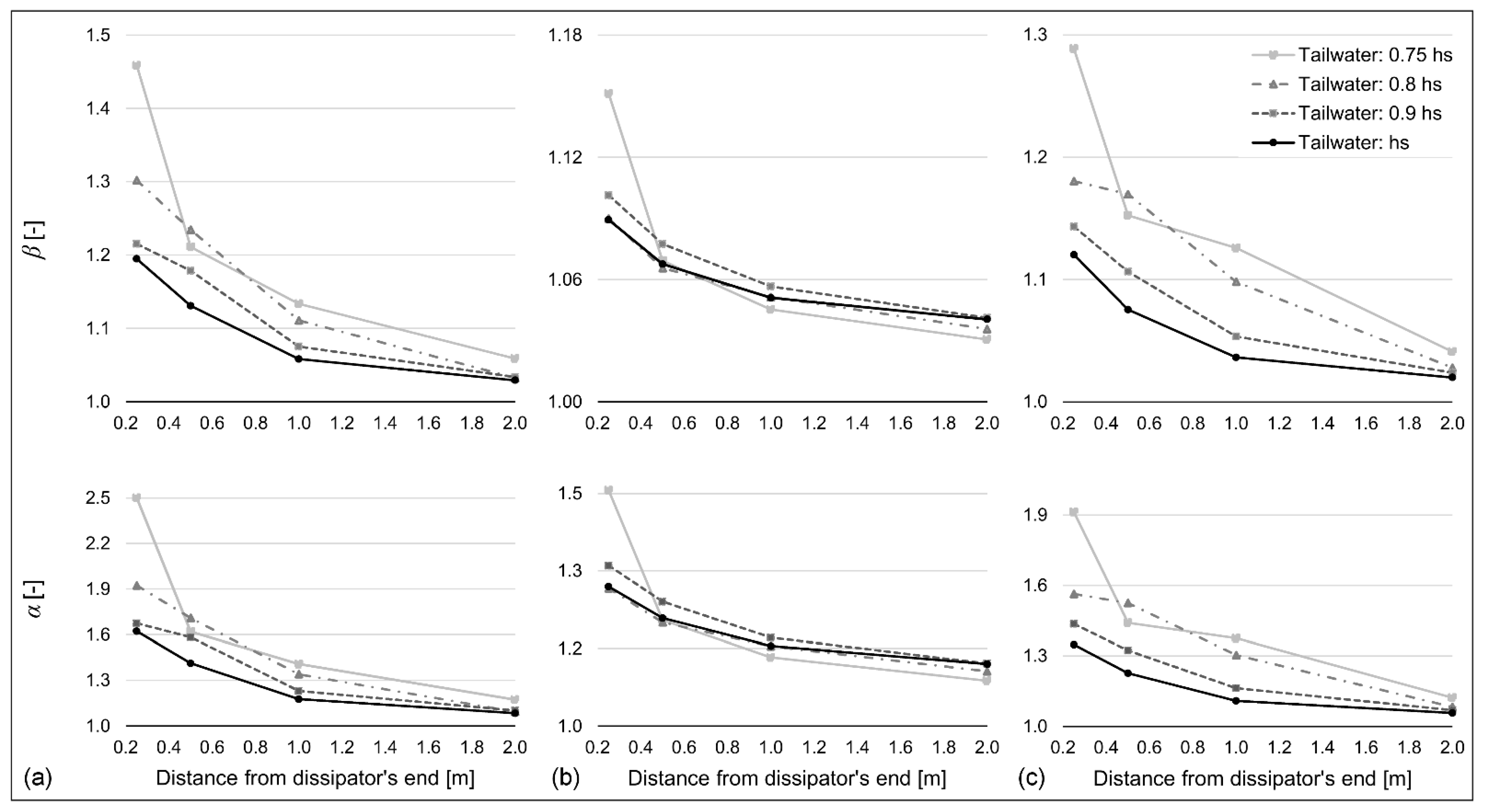
As expected, the flow becomes gradually more uniform when moving towards the downstream part of the flume. Higher values of α and β were registered in the first measurement section under the lowest tailwater condition (0.75 hs), as a consequence of a local non-stationary phenomenon characterized by a plunging effect and local oscillating water depth immediately downstream from the device, associated with pronounced air entrainment near the free surface. Except for this anomaly, the performance of Configuration 2 was found to be particularly stable also for lower tailwater levels, showing the ability of the system in stabilizing the hydraulic jump, even with lower force available downstream.
With lower tailwater conditions, the percentage of the energy dissipated in the stilling basin was increased, allowing for better exploration of the stabilization capabilities of the device. The maximum increase was registered for Configurations 1 and 2, changing from 74% under
hs to about 79% under 0.75
hs. Additionally, since in this last phase of the experiments the velocity measurements were available for four whole cross-sections on a regular grid, it was also possible to evaluate the error induced by assuming
αb = α or neglecting it in the computation of the dissipated energy, observing that the use of
αb instead of α causes an average error of 0.15%, with a maximum value of 1.16%, while neglecting it (i.e.,
α = 1) leads to an average error of 0.38%, thus confirming the suitability of approximating
α with
αb. Moreover, in these experiments, the values of
α and
β were found to be linearly dependent, according to the equation
(R
2 = 0.9975), in line with the observations of Mohanty et al. [
31].
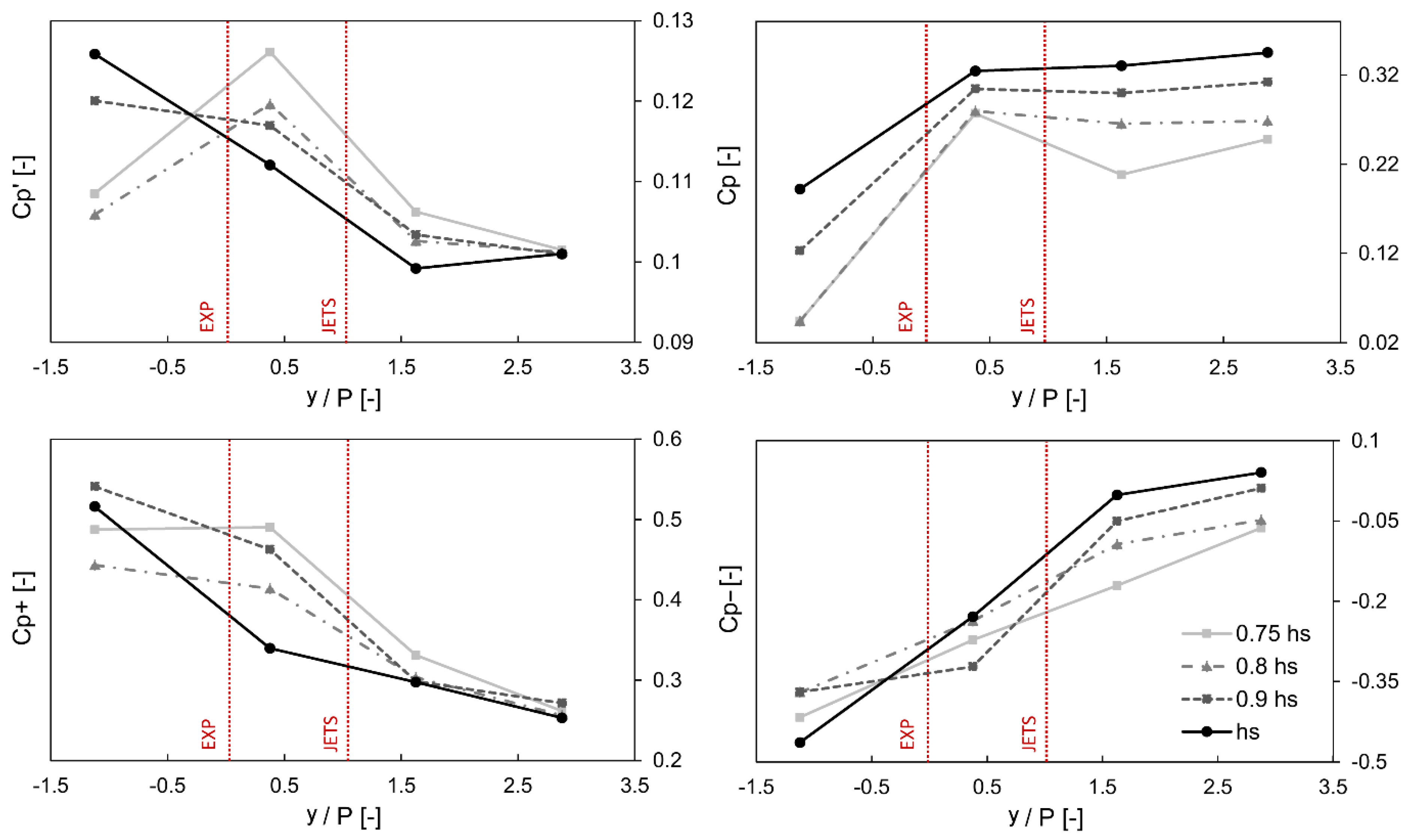
Finally,
Figure 8 shows the calculated dimensionless bed pressure coefficients, measuring the standard deviation, mean, and maximum positive and negative deviations from the mean (Equations (5)–(7)) of the pressure fluctuations along the centerline of the flume, under
Fr = 7.4 and different tailwater levels, as a function of
y/P,
y being the distance of each pressure transducer from the position of the counterflow jets (
y/P = 1 indicates the position of the device, while
y/P = 0 the expansion section).
Figure 8 refers to Configuration 1, but very similar trends have also been observed for the other two configurations considered, which are not reported here for the sake of conciseness. The panel for the mean pressure
Cp roughly resembles the water surface profile, while the other plots in
Figure 8 corroborate the qualitative description of the flow features provided in
Figure 4.
Indeed,
Figure 8 shows a reduction of the pressure fluctuations in the downstream part of the tailwater channel for all the tested tailwater depths, indicating that most of the turbulence occurs within the basin, also with maximum positive and negative pressure deviations, reaching
Cp± values of about 0.5 in the expansion area.
Cp′ was found to increase when moving from
hs to 0.75
hs, because of the additional turbulent structures induced by the jets.
However, it can be observed that minimum values attained for
Cp′ at
y/P = 2.87 (
Cp′ ~ 0.1) were a bit larger than those reported in the literature for hydraulic jumps [
29,
32,
33], suggesting that, in spite of the quite uniform flow velocity field registered (
Figure 7), bed pressure oscillations are not completely contained within the basin, mainly as a consequence of the reported water surface fluctuations in the area downstream from the device [
34].


 ,
, 


