Simulation and Verification of Hydraulic Performance and Energy Dissipation Mechanism of Perforated Drip Irrigation Emitters


1
College of Water Resources and Architectural Engineering, Shihezi University, Shihezi 832000, China
2
Key Laboratory of Modern Water-Saving Irrigation of Xinjiang Production and Construction Corps, Shihezi University, Shihezi 832000, China
3
College of Water Resources and Civil Engineering, China Agricultural University, Beijing 100083, China
*
Authors to whom correspondence should be addressed.
Water 2021, 13(2), 171; https://doi.org/10.3390/w13020171
Submission received: 23 November 2020
/
Revised: 27 December 2020
/
Accepted: 8 January 2021
/
Published: 13 January 2021
(This article belongs to the Special Issue Water Conservation in Irrigated Agricultural Systems)
Abstract
:Drip irrigation has become an application trend of water-saving irrigation technology due to its excellent water-use efficiency. However, the energy dissipation form of the commonly used labyrinth channel is relatively simple, and the corresponding energy dissipation mechanism research is inadequate. This article proposes a new kind of channel structure of drip irrigation emitters based on the structure of scalariform perforation plates in plant xylem vessels. We establish a total of 16 sets of orthogonal structure schemes. Using numerical simulation and physical experiments, the hydraulic performance and energy dissipation mechanism of the perforated drip irrigation emitters (PDIE) are studied. The results show that the flow index of PDIE is 0.4665–0.5266. The hydraulic performance of PDIE in the high-pressure zone is the best, and the flow index is 0.4665–0.5046. As the pressure increases, the velocity of the flow of the upper perforation increases rapidly, the flow ratio decreases, the flow index decreases, and the hydraulic performance improves. To further verify the energy dissipation mechanism, a lower flow ratio and a better hydraulic performance were obtained through appropriately expanding the upper part of the upper perforation inlet to the channel boundary. The research sheds new insights for optimizing the hydraulic performance of PDIE. Results reported here provide a theoretical basis for the structural design of drip irrigation emitters and the energy dissipation mechanism research.
1. Introduction
Drip irrigation emitter is an important part of a micro-irrigation system. It transforms continuous jet into uniform and stable dripping flow, stabilizing flow and reducing pressure [1]. The sensitivity of the drip irrigation emitter’s discharge rate to change with working pressure is called hydraulic performance [2]. The structure and energy dissipation of the emitters are closely related to the hydraulic performance [3]. Therefore, it is of great significance to explore the structure design and energy dissipation mechanism of drip irrigation emitters to improve the micro-irrigation system’s performance.
At present, the numerical simulation based on computational fluid dynamics (CFD), experimental test, and theoretical analysis based on fluid mechanics are the main research methods for the hydraulic performance and energy dissipation mechanism of drip irrigation emitters. The experimental test is mainly used to study the hydraulic performance and anti-clogging performance of drip irrigation emitters [4,5]. Further, numerical simulation is the primary method to analyze the flow field in the flow passage to explore energy dissipation and blockage [6].
The labyrinth channel is a typical channel structure at present. Many scholars have conducted in-depth research on labyrinth channel drip irrigation emitters by the CFD software package. Based on the CFD software package, Wei et al. [7] calculated the relationship between the pressure and the internal velocity distribution of the emitters for three different drip irrigation emitters. The results showed that the simulation values were in good agreement with the test results. Zhang et al. [8] calculated the relationship between the drip irrigation emitters’ flow rate and working pressure through the CFD software package and obtained the flow field distribution in the arc labyrinth channels. The results of the simulation are consistent with the test results of the enlarged physical model. Li et al. [9] compared the CFD calculation results with the test results by the two-dimensional digital particle-tracking velocimetry visualization system of the full flow field. The authors suggested that the CFD software package can optimize the structure of drip irrigation emitters. Liu et al. [6] measured the drip irrigation emitters’ flow field under different pressures through digital particle image velocimetry. The authors further indicated that the flow channel’s vortex could improve the emitter’s self-cleaning ability and anti-blocking ability. Guo et al. [10] analyzed the two-ways mixed-flow emitters from the macroscopic flow rate and microscopic velocity. They believe that when the flow ratio of the forward and reverse flow of the two-ways mixed-flow emitter is closer to 1, the hydraulic performance of two-ways mixed-flow emitters is better. Yu et al. [11] found a good angle range of labyrinth channel of drip irrigation emitters and appropriate numerical analysis methods by analyzing the distribution of sand particles in the labyrinth channel at different corners and with computational fluid dynamics discrete element method. Wu et al. [12] used CFD to study the flow in the channel of labyrinth drip irrigation emitters, in which the anti-clogging performance of these emitters was carried out by way of analyzing the velocity distribution characteristics in different cross-sections of the same structure unit.
Besides, some scholars have proposed new types of drip irrigation emitters based on the labyrinth channel. Li et al. [13] designed a fully turbulent channel by introducing the fractal curve constructed by fractal theory into the labyrinth channel design. Long et al. [14] built a rectangular labyrinth channel drip irrigation emitter with double internal teeth with a better hydraulic performance by adding internal teeth to the rectangular labyrinth channel drip irrigation emitters. Feng et al. [3] improved the emitters’ anti-clogging performance and hydraulic performance by removing the low-speed vortex area in the channel according to the primary channel design method. Tian et al. [15] proposed a bidirectional flow channel of drip irrigation emitters. They combined orthogonal experiments and numerical simulations to explore the bidirectional flow channel’s energy dissipation mechanism.
Many new types of drip irrigation emitters, such as Barbed labyrinth channel emitters [16], Divided-flow emitters [17], and Pit drip irrigation emitters [18], put forward different ideas for the design and optimization of the drip irrigation emitters.
According to the mode of energy dissipation and the structure of the flow channel, the commonly used drip irrigation emitters are divided into labyrinth emitters and pipe-type pressure compensating emitters. The labyrinth channel irrigation emitter is simple in structure and straightforward in energy dissipation [16,19]. The pipe-type pressure compensating emitter has good hydraulic performance, but its design is intricate, and there are some problems such as diaphragm aging [20]. Most research focuses on the relationship between the structural parameters and hydraulic performance of the drip irrigation emitters’ channel. However, the mechanism of energy dissipation is seldom studied. Based on the perforated drip irrigation emitters (PDIE) developed by the author team, this study adopts the CFD software package for numerical simulation, proposes a numerical simulation method suitable for PDIE, and further analyzes the hydraulic performance and energy dissipation mechanism of PDIE according to the flow field of the channel. This work is meaningful for optimizing the hydraulic performance of PDIE, which can provide a theoretical basis for the structural design of the drip irrigation emitters and the study of the energy dissipation mechanism.
2. Materials and Methods
2.1. Control Equation
The flow in the PDIE can be approximated as viscous incompressible fluid motion.
The continuity equation is as follows:
The momentum equation is as follows:
where is the flow velocity, m/s; u, v, and w are the velocity components of fluid particles in the three-dimensional space direction x, y, and z respectively, m/s; ρ is the density of water, kg/m3; μ is dynamic viscosity, N·s/m2; p is the pressure on the fluid, Pa; Fu, Fv, and Fw are the force of fluid particles in the three-dimensional direction x, y, and z, N/m3.
The flow index equation is as follows:
where q is the channel’s average flow rate, l/h; x is the flow index, and H is the inlet pressure, MPa.
The relative error equation is as follows:
where δ is the relative error; m is the test value, l/h; and n is the simulated value, l/h.
2.2. Numerical Simulation Model
2.2.1. Structure and Geometric Parameters
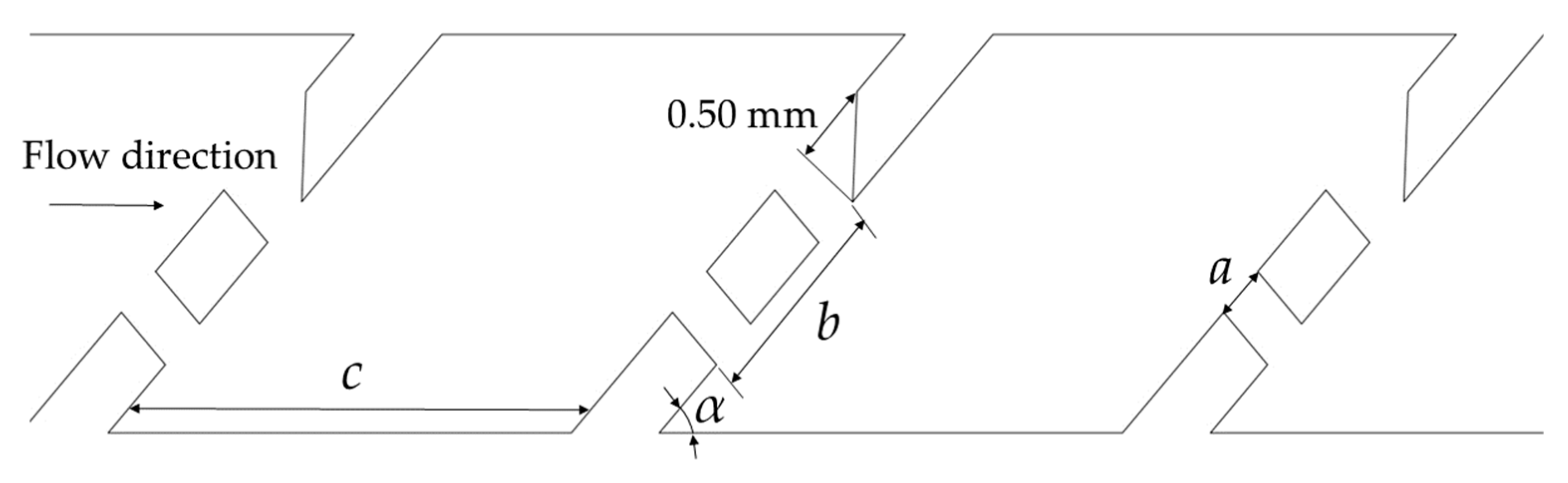
The PDIE is designed according to the structure of scalariform perforation plates (SPP) in plant xylem vessels (Figure 1) [21]. The structure of PDIE is shown in Figure 2, where a is the width of the perforation, b is the distance to the far side of the two perforations, c is the length of the channel cavity, and α is the scalariform angle perforation plate. The value range of critical structural parameters of the channel is as follows: a is 0.25 mm–0.40 mm, with values of 0.05 mm at intervals; b is 1.20–1.50 mm, with value every 0.10 mm; c is 3.10 mm–3.70 mm, with value every 0.20 mm; α is 45°–60° and is evaluated at intervals of 5°. There are altogether four parameters and four levels. The channel width is 2.70 mm, the depth is 0.80 mm, the scalariform perforation plate width is 0.45 mm, and the number of the PDIE units is 15.
2.2.2. 3D Modeling and Mesh Independence Analysis
3D modeling of PDIE based on SolidWorks 2018 (appropriately lengthens the inlet section of the channel to make the flow fully develop). The ICEM CFD (ver.19.0) was used to divide the channel into unstructured grids. In order to ensure high computational efficiency and reduce the influence of mesh on the calculation results, the maximum mesh size of 0.20, 0.19, 0.18, 0.17, 0.15, 0.14, 0.13, 0.12, 0.11, 0.10, 0.09, 0.08, 0.07, and 0.05 mm, respectively, was selected to calculate the flow rate of the PDIE under the pressure of 0.10 MPa with Fluent 19.0. Considering the calculation accuracy and efficiency comprehensively, when the difference of the calculation results is less than 0.5%, it is considered that the number of grids does not influence the calculation results [18]. Therefore, the maximum grid size was set as 0.07 mm in ICEM CFD. The total number of perforated drip irrigation emitter channel grids is about 3.1 million, as shown in Figure 3.
2.2.3. Fluent Setup
The flow field of the perforated drip irrigation emitter channel is turbulent except for near the wall. This study uses the standard k-ε model to calculate the flow field inside the channel. The inlet was set as the pressure inlet, and the set values were 0.05, 0.075, 0.10, 0.125, 0.15, 0.175, 0.20, 0.225, 0.25, 0.275, and 0.30 MPa, respectively. The outlet is set as the pressure outlet, and the set value is 0 MPa. No-slip boundary and enhanced wall function are adopted for all walls. An uncoupled implicit algorithm is used in the numerical simulation of the PDIE. Among them, in the Controls-Solution Controls option setting of Solve, set the pressure term, momentum term, turbulent kinetic energy term, and specific dissipation rate term as the more accurate second-order upwind formula. To reduce the iterative calculation error and increase the convergence accuracy, the residual convergence standard of the Monitors-Residual Monitors item in Solve is adjusted to 1 × 10⁻⁴. To improve the stability of the simulation calculation, the pressure and velocity coupling adopt the SIMPLE solver, and the simulated calculated flow rate value under different inlet pressures is compared with the experimental value [11].
2.3. PDIE Simulation
2.3.1. Influence Factors of Flow Index
The structure parameters of PDIE are four factors and four levels. The structural schemes of PDIE are designed according to the orthogonal experimental design table L16(45) [22]. The structural schemes are shown in Table 1. The other structural parameters are fixed values [15].
In the performance study of drip irrigation emitters, the flow index reflects the sensitivity of flow rate to pressure change. The smaller the flow index, the better the hydraulic performance of the drip irrigation emitters [18]. In this work, we used Stata16 to obtain the flow indexes and correlation coefficients of 16 groups of structural schemes and three pressure areas (0.05–0.10, 0.10–0.20, and 0.20–0.30 MPa) through multiple regression fitting of pressure and flow rate.
To analyze the effects of the flow ratio between the upper side perforation and the lower side perforation of the scalariform perforation plates on the flow index, the flow rate of lower side perforation is defined as Q1, the flow rate of upper side perforation is Q2, and Q1/Q2 represents the ratio of the flow rates on both sides. Q1 and Q2 are calculated by the Surface Integrals function of fluent based on the cross-section parallel to the scalariform perforation plates. Figure 2 shows the flow direction of Q1 and Q2.
2.3.2. Velocity Distribution
The structural scheme 11 with the flow index in the low-pressure area as an example is taken. The simulation results of Fluent 19.0 at the inlet pressures of 0.10 MPa and 0.20 MPa were imported into Tecplot 360 EX 2016. By Tecplot 360 EX 2016, velocity distribution diagram of the middle longitudinal section of the second and third units of the perforated drip irrigation emitters under the working pressure of 0.10 MPa and 0.20 MPa for the structural scheme 11 were obtained.
2.4. Experimental Verification
To verify the reliability of numerical simulations, a numerical control machine tool with a machining accuracy of 0.01 mm and a repeat positioning accuracy of 0.005 mm was used to produce PDIE samples in equal proportions to transparent and colorless acrylic material. A high-power microscope was used to check the size. Process 5 groups of test samples (Figure 4b). Each set of samples includes five pieces. The test inlet pressures were 0.05, 0.075, 0.10, 0.125, 0.15, 0.175, 0.20, 0.225, and 0.25 MPa (Figure 4a). Each sample is tested three times, and each test time is five minutes. The flow rate of PDIE under different pressures was tested by the measuring cylinder volume method, and an electronic balance with an accuracy of 0.001 g was used to check. Take the average of the test result and the simulation value for mutual comparison.
3. Results
3.1. Effects of Pressure on the Flow Index
The flow index of 16 structural schemes of PDIE are different in 0.05–0.10, 0.10–0.20, and 0.20–0.30 MPa. The simulation results of flow indexes are shown in Table 2. The flow indexes of 16 groups of structural schemes are 0.4665–0.5266. Under the same structural scheme, the flow rate of the PDIE increases with the increase of inlet pressure. The flow index of PDIE decreases as the pressure increases. The pressure of PDIE increased by five times, resulting in an average decrease of 5.39% in the flow index of the high-pressure zone relative to the flow index of the low-pressure zone and an average decrease of 2.83% in the flow index of the medium-pressure zone than the flow index of the low-pressure zone. The flow rate is less sensitive to working pressure. PDIE has an excellent hydraulic performance. The relative error between the simulated value and the experimental value is 1.381–2.439%, indicating that the simulation calculation results are reliable. The relative error between the simulated value and the measured value is calculated for each structural scheme and each pressure. The relative error of structural scheme 1 is 2.439% under 0.30 MPa, which is the largest among the 16 structural schemes. The relative error of structural scheme 13 is 1.381% under 0.05 MPa, which is the smallest of the 16 structural schemes. Correlation coefficients of the pressure-flow curves of the simulation values of the 16 structural schemes are all higher than 0.998. Taking the structural scheme 13 and the structural scheme 1 as examples to draw the pressure-flow relationship curve, as shown in Figure 5.
3.2. Effects of Flow Ratio on Flow Index
By calculating the flow rates of the upper side perforations and the lower side perforations in 16 structural schemes, the flow rate of the lower side flow and the flow rate of upper side flow within 0.05–0.30 MPa were obtained, as shown in Table 3. The smaller Q1/Q2 is, the greater the ratio of Q2 to the total flow rate, the smaller the flow index of the PDIE, and the better the hydraulic performance. Conversely, the greater the ratio of Q1 to the total flow rate, the more outstanding the flow index is and the worse the hydraulic performance is. The flow ratio decreases as the pressure increases. The flow ratio of the high-pressure zones decreased by 1.46% compared with the average flow ratio in the low-pressure zone, and the flow index decreased by an average of 5.39%. The flow ratio in the medium-pressure zone decreased by 0.82% compared with the flow ratio in the low-pressure zone, and the flow index decreased by 2.33% on average.
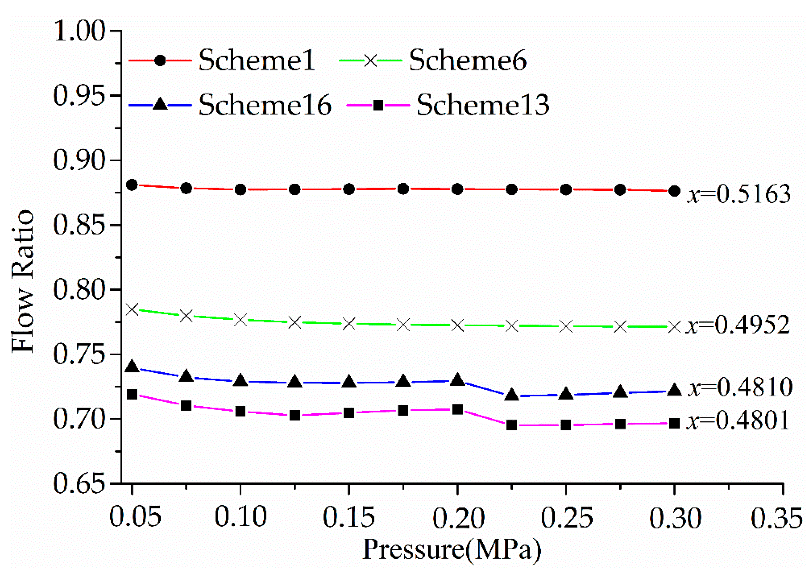
The flow ratio and hydraulic performance of PDIE were analyzed in depth by taking scheme 1 and 6 with larger flow indexes and scheme 16 and 13 with smaller flow indexes among 16 structural schemes as examples. The relationship curve between the flow ratio and the flow index of the four groups of structural schemes is shown in Figure 6. As the pressure increases, both Q1 and Q2 increase, and the flow ratio drops slowly. This result indicates that Q2 is growing faster than Q1. The flow ratio of these structural schemes with smaller flow indexes is also smaller, and its curve change trend is more pronounced. For the decrease of each pressure area’s average flow ratio, the reduction of scheme 1 is 0.18%, scheme 6 is 0.58%, scheme 16 is 0.83%, and scheme 13 is 1.05%.
3.3. Energy Dissipation Mechanism and Velocity Distribution
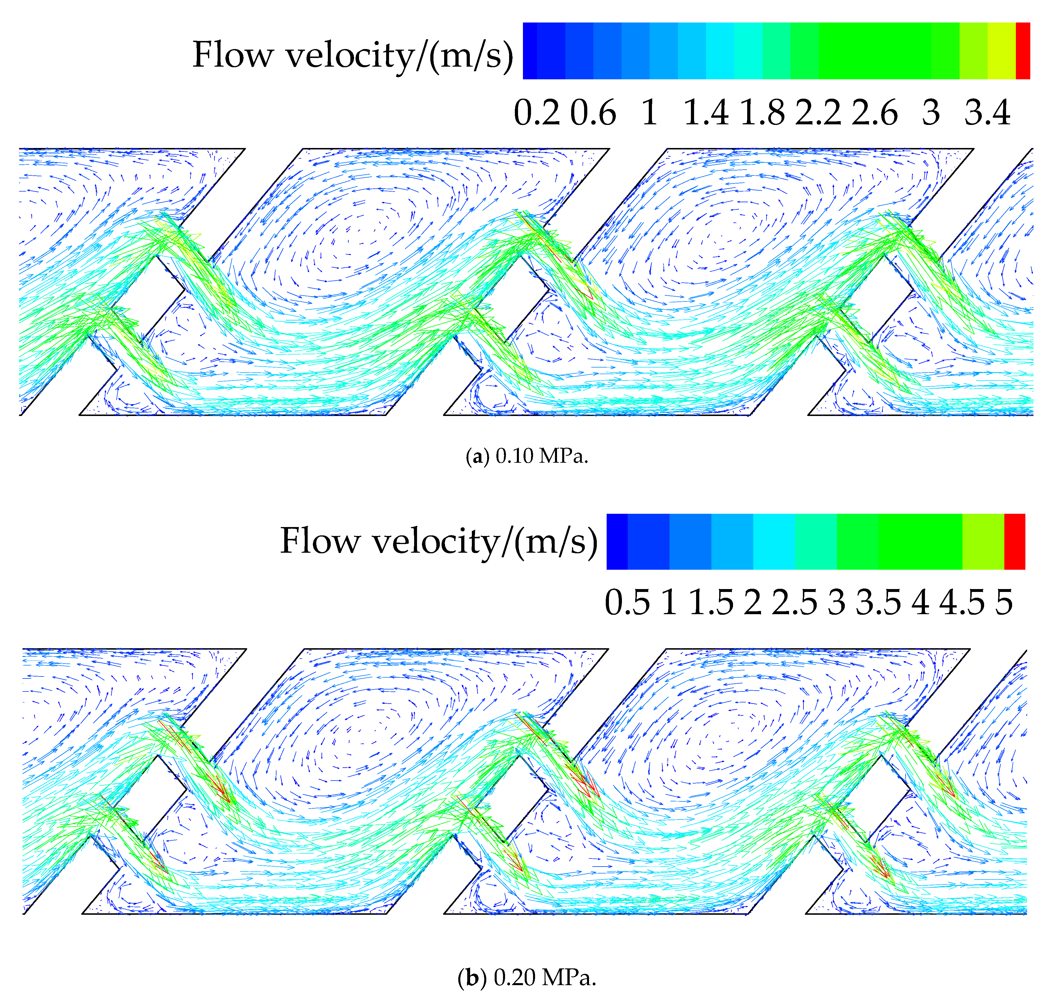
The velocity distribution and energy dissipation mechanism between different structural schemes of PDIE are similar. Taking scheme 11 with middle flow index in low-pressure area as an example, the flow field and energy dissipation mechanism of PDIE are analyzed from the perspective of microscopic velocity. Figure 7 is a velocity distribution diagram of the middle longitudinal section of the second and third units of the PDIE under the working pressure of 0.10 MPa and 0.20 MPa for the structural scheme 11.
By observing the velocity distribution of the perforated drip irrigation emitters (Figure 7), the flow changes direction under the shunt action of the scalariform perforation plate and forms two high-speed streams passing through two perforations. The velocity of lower side flow drops after impacting the wall of the channel. Then, the lower side flow is mixed with the upper side flow to form a flow. In this process, the velocity drops significantly, and the energy dissipation is excellent. The two streams form the mainstream with high velocity. The mainstream with higher velocity and the vortex area with lower velocity are mixed continuously, and the energy is further consumed. These combined effects produce a steady drip flow from the perforated drip irrigation emitters.
The average velocity of streams of two sides at the outlet of perforations was calculated by the “Report” in Fluent. The cross-sectional areas of the perforations on both sides are equal. Under the working pressure of 0.10 MPa, the velocity of the upper side flow is 2.99 m/s, the velocity of the lower side flow is 2.83 m/s, and the velocity of the lower side flow is smaller than that of the upper side flow. Under the working pressure of 0.20 MPa, the velocity of the upper side flow is 3.51 m/s, and the velocity of the lower side flow is 2.92 m/s. The increase in the velocity in the upper side flow is 1.01 m/s. The velocity increase in the lower side flow is 0.84 m/s. The rise of 1.01 m/s in the upper side flow velocity is more significant than the rise of 0.84 m/s in the lower side flow. Therefore, the flow rate of the upper side flow increased more than that of the lower side flow. The working pressure of PDIE increases, the flow ratio decreases, and the flow index also decreases.
3.4. Structure Optimization Based on Energy Dissipation Mechanism
Above, the relationship between the macroscopic flow rate ratio and the hydraulic performance of PDIE under different pressures and the relationship between the microscopic flow rate and the hydraulic performance of PDIE have been analyzed. The results show that the lower the flow ratio, the smaller the flow index, and the better the hydraulic performance. According to the energy dissipation mechanism, to reduce the flow ratio, the inlet of the upper side perforation can be enlarged to adjust its flow rate and improve the hydraulic performance of PDIE.
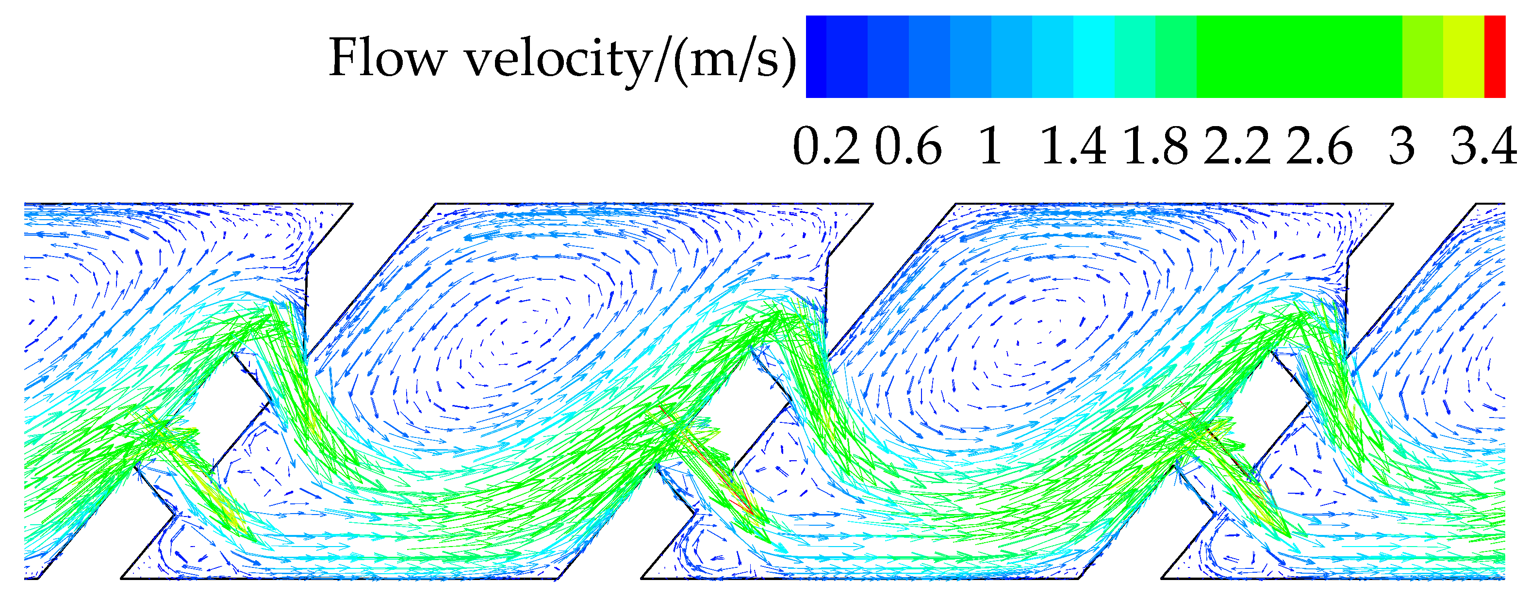
To further prove the energy dissipation mechanism described above, we take structural scheme 11 that is one of 16 group structural schemes of PDIE as an example. After many attempts, the upper side of the inlet of the upper perforation was finally enlarged by 0.50 mm in the direction of the wall of the channel, as shown in Figure 8. The velocity distribution of the optimized structural scheme 11 under 0.10 MPa working pressure is shown in Figure 9.
In the optimized structural scheme, under a pressure of 0.10 MPa, the velocity of the upper side flow is 2.32 m/s, and the velocity of the lower side flow is 1.91 m/s. The flow ratio decreased from 0.777 to 0.709, falling by 8.75%. The flow index of the optimized scheme obtained by simulation calculation is 0.4940 in the low-pressure zone, 0.4825 in the medium-pressure zone, and 0.4726 in the high-pressure zone. The flow index in the low-pressure area and medium-pressure area decreased by 2.12% and 0.64%, respectively, and that in the high-pressure area increased by 0.30%. The hydraulic performance of PDIE is obviously improved.
4. Discussion
At present, the primary method to improve the performance of drip irrigation emitters is to optimize the channel structure [3,11]. Based on the design of scalariform perforation plates in plant xylem vessels [21], this study proposed a kind of perforated drip irrigation emitter and conducted orthogonal experiments on the four main structural parameters extracted to explore the hydraulic performance and energy dissipation mechanism of PDIE.
In this work, physical experiments and simulation calculations were carried out on the flow rate of PDIE. The relative error between the simulated values and the test results of PDIE is 1.381–2.439%, and the correlation coefficients of pressure-flow rate curves are all higher than 0.998, indicating that the calculations method of the CFD software package is reliable. Therefore, this method can be used to study perforated drip irrigation emitters. The simulation calculation shows that the flow index of PDIE is 0.4665–0.5266. Like Xu et al. [18], we found the most of the test values are less than the simulated values. A possible explanation is that the wall of the prototype cannot be processed to be smooth, which causes the flow rate to produce additional energy dissipation inside the performance of drip irrigation emitter.
The main reason why the flow index of PDIE in the high-pressure area is better than that of the middle- and the low-pressure regions is the increase in pressure, which leads to a rise in the flow rate of the two perforations’ streams. The increasing flow rate causes hedging between the two streams is intensified, the mixing between the mainstream zone and the vortex zone is amplified, and the energy consumption increases [10]. In the low-pressure area of 0.05–0.10 MPa, the minimum flow index of the perforated drip irrigation emitter is 0.4919, whereas the flow index of the labyrinth channel drip irrigation emitter under the same working pressure is generally above 0.5 [15]. The hydraulic performance of PDIE is better than that of the common labyrinth drip irrigation emitter in each pressure range. Under the same working pressure, PDIE can provide a more stable and uniform flow rate, which has positive value for improving irrigation efficiency and reducing irrigation project investment [1].
The better the hydraulic performance of the structural scheme, the lower the flow index is, the more significant the decrease of Q1/Q2 is with the pressure increase, and the smaller is the value of Q1/Q2. PDIE has a similar energy dissipation mechanism to the bidirectional flow channel of drip irrigation emitters [15]. The velocity distribution shows that the main energy consumption of PDIE is due to the mixing of two streams formed by the scalariform perforation plate. The increase of PDIE’s working pressure causes Q1 and Q2 to increase, and the rise in Q2 is more remarkable than Q1. This results in a decrease in flow ratio and flow index and, thus, the improvement of hydraulic performance. Therefore, the flow ratio can be optimized by appropriately adjusting the structure of the upper side perforation of the scalariform perforation plate. Moreover, the collision and mixing of two streams can be enhanced to improve the perforated drip irrigation emitters’ hydraulic performance.
After optimizing the structure of PDIE based on the above energy dissipation mechanism, the flow index in the low-pressure area and medium-pressure area decreased by 2.12% and 0.64%, respectively, and that in the high-pressure area increased by 0.30%. The optimized scheme results verify the energy dissipation mechanism obtained in this work and provide a theoretical basis for the further optimization of the hydraulic performance of PDIE. The possible reason for the small change of the flow index in the high-pressure area is that the high-pressure area’s velocity is high enough, and the energy dissipation in the original structural scheme is relatively complete.
Nevertheless, Guo et al. [10] studied the energy dissipation mechanism of two-ways mixed-flow drip irrigation emitters. His work shows that the flow ratio of positive flow and negative flow is closer to 1, and the hydraulic performance of two-ways mixed-flow drip irrigation emitters is better. His research differs significantly from the results of this study. The reason may be that the two-ways mixed-flow drip irrigation emitters form the positive and negative flow of water, which directly impact each other. In contrast, the two flows of PDIE in the same direction mainly occur at the side of the flow.
Finally, to further improve the plugging resistance and hydraulic performance of perforated emitter, some problems still need to be studied.
- Integrating with the energy dissipation mechanism, the effects of structural parameters on hydraulic performance can be researched to improve the hydraulic performance of PDIE [23].
- Various particle sizes were added in the experiment and combined with particle image velocimetry to study the effects of different structural parameters on the anti-clog performance of PDIE [6].
- Besides, the impact of the lower side flow and the wall of the channel and the mixing of the main flow area with higher velocity and the vortex area with a lower flow rate will also consume energy. On the one hand, the vortex area can improve the drip irrigation emitter’s energy dissipation effect, slow down the attachment of viscous clogging material on the wall, and promote detachment [3].
In this work, the hydraulic performance of PDIE was analyzed from the perspective of macroscopic flow ratio and microscopic velocity, starting from the energy dissipation mechanism. The results show that appropriately increasing the perforation flow rate on the upper side can enhance the mixing and collision of the two streams and improve the energy dissipation effect and hydraulic performance of PDIE. To comprehensively study the potential connection of anti-blocking performance, hydraulic performance, and geometric structure, the structural parameters of PDIE can be further optimized based on the channel structure of emitters. To improve the anti-blocking performance of perforated drip irrigation emitters, particle image velocity measurement technology should be combined to study the influence of working pressure and structural parameters on the drip irrigation emitters’ anti-clogging performance to improve the anti-blocking performance of PDIE.
5. Conclusions
In this work, the hydraulic performance of PDIE was analyzed from the perspective of macroscopic flow ratio and microscopic velocity, starting from the energy dissipation mechanism. The maximum relative error between the simulation flow rate of the perforated drip irrigation emitters and the test flow rate is 2.439%. The flow rates of the simulation are reasonable, which can provide a theoretical reference for exploring the energy dissipation mechanism and hydraulic performance of the perforated drip irrigation emitters. Sixteen structural schemes designed by orthogonal experiments show that the flow index of perforated drip irrigation emitters is 0.4665–0.5266. The hydraulic performance of perforated drip irrigation emitters is excellent. The hydraulic performance of the high-pressure area is better than that of the medium- pressure and low-pressure areas. The perforated drip irrigation emitters mainly consume energy through the hedge of the two water streams formed by the scalariform perforation plate. The hydraulic performance of perforated drip irrigation emitters can be improved by optimizing the flow ratio.
Author Contributions
Z.W. and J.Z. provided the idea of the study and writing of the manuscript; S.X. conducted the data analysis; N.L. and B.Z. provided important advice on the concept of the methodology. All authors have read and agreed to the published version of the manuscript.
Funding
This work was supported by the National Key Research and Development Program of China (2017YFC0403205), Innovation and Development Project of Shihezi University (CXFZ201905), and Innovation Team Project in Key Fields of Xinjiang Production and Construction Corps (2019CB004).
Institutional Review Board Statement
Not applicable.
Informed Consent Statement
Not applicable.
Data Availability Statement
The data that support the finding of this study are available from the corresponding author upon reasonable request.
Acknowledgments
We sincerely thank the College of Water Resources and Architectural Engineering (Shihezi University) for providing the experimental site.
Conflicts of Interest
The authors declare no conflict of interest.
Abbreviations
| PDIE | Perforated drip irrigation emitters |
| SPP | Scalariform perforation plates |
| CFD | Computational fluid dynamics |
References
- Madramootoo, C.A.; Morrison, J. Advances and challenges with micro-irrigation. Irrig. Drain. 2013, 62, 255–261. [Google Scholar] [CrossRef]
- Lin, Z.; Gary, P.M. Relationships between common irrigation application uniformity indicators. Irrig. Sci. 2012, 30, 83–88. [Google Scholar]
- Feng, J.; Li, Y.; Wang, W.; Xue, S. Effect of optimization forms of flow path on emitter hydraulic and anti-clogging performance in drip irrigation system. Irrig. Sci. 2018, 36, 37–47. [Google Scholar] [CrossRef]
- Al-Amoud, A.I.; Mattar, M.A.; Ateia, M.I. Impact of water temperature and structural parameters on the hydraulic labyrinth-channel emitter performance. Span. J. Agric. Res. 2014, 12, 580–593. [Google Scholar] [CrossRef] [Green Version]
- Lili, Z.; Yang, P.; Zheng, W.; Li, Y.; Liu, Y.; Zhang, C. Effects of water salinity on emitter clogging in surface drip irrigation systems. Irrig. Sci. 2020. [Google Scholar] [CrossRef]
- Liu, H.; Li, Y.; Liu, Y.; Yang, P.; Ren, S.; Wei, R.; Xu, H. Flow Characteristics in Energy Dissipation Units of Labyrinth Path in the Drip Irrigation Emitters with DPIV Technology. J. Hydrodyn. 2010, 22, 137–145. [Google Scholar] [CrossRef]
- Wei, Q.; Shi, Y.; Dong, W.; Lu, G.; Huang, S. Study on hydraulic performance of drip emitters by computational fluid dynamics. Agric. Water Manag. 2006, 84, 130–136. [Google Scholar] [CrossRef]
- Zhang, J.; Zhao, W.; Wei, Z.; Tang, Y.; Lu, B. Numerical and experimental study on hydraulic performance of emitters with arc labyrinth channels. Comput. Electron. Agric. 2007, 56, 120–129. [Google Scholar] [CrossRef]
- Li, Y.; Yang, P.; Xu, T.; Ren, S.; Lin, X.; Wei, R.; Xu, H. CFD and digital particle tracking to assess flow characteristics in the labyrinth flow path of a drip irrigation emitter. Irrig. Sci. 2008, 26, 427–438. [Google Scholar] [CrossRef]
- Guo, L.; Bai, D.; Wang, X.; He, J.; Zhou, W.; Cheng, P. Numerical simulation and verification of hydraulic performance and energy dissipation mechanism of two-ways mixed flow emitter. Trans. Chin. Soc. Agric. Eng. 2017, 33, 100–107, (In Chinese with English Abstract). [Google Scholar]
- Yu, L.; Li, N.; Liu, X.; Yang, Q.; Li, Z.; Long, J. Influence of Dentation Angle of Labyrinth Channel of Drip Emitters on Hydraulic and Anti-Clogging Performance. Irrig. Drain. 2018, 68, 256–267. [Google Scholar] [CrossRef]
- Wu, D.; Li, Y.; Liu, H.; Yang, P.; Sun, H.; Liu, Y. Simulation of the flow characteristics of a drip irrigation emitter with large eddy methods. Math. Comput. Model. 2013, 58, 497–506. [Google Scholar] [CrossRef]
- Li, Y. Effects of fractal flow path designing and its parameters on emitter hydraulic performance. Chin. J. Mech. Eng. 2007. [Google Scholar] [CrossRef]
- Long, J.; Zhiqin, L.I.; Yanchao, M.A.; Chao, W. Analysis of Double Gear Rectangular Labyrinth Hydraulic Characteristics. J. Taiyuan Univ. Technol. 2016, 47, 774–778, (In Chinese with English Abstract). [Google Scholar]
- Tian, J.; Bai, D.; Yu, F.; Wang, X.; Guo, L. Numerical simulation of hydraulic performance on bidirectional flow channel of drip irrigation emitter using Fluent. Trans. Chin. Soc. Agric. Eng. 2014, 30, 65–71, (In Chinese with English Abstract). [Google Scholar]
- Ma, R.; Wei, Z.; Chen, X.; Ma, S. Barbed labyrinth channel optimization based on constrained multi-objective particle swarm algorithm. J. Drain. Irrig. Mach. Eng. 2018, 36, 1330–1336, (In Chinese with English Abstract). [Google Scholar]
- Yuan, W.; Wei, Z.; Chu, H.; Ma, S. Optimal design and experiment for divided-flow emitter in drip irrigation. Trans. Chin. Soc. Agric. Eng. 2014, 30, 117–124, (In Chinese with English Abstract). [Google Scholar]
- Xu, T.; Zhang, L. Influence and analysis of structure design and optimization on the performance of a pit drip irrigation emitter*. Irrig. Drain. 2020. [Google Scholar] [CrossRef]
- Li, Z.; Ma, J. Experiment on flow pattern in labyrinth emitter. Trans. Chin. Soc. Agric. Eng. 2012, 28, 82–86, (In Chinese with English Abstract). [Google Scholar]
- Wei, Z.; Yuan, W.; Zhou, X.; Zhao, G. Research Progress of Pressure Compensating Emitters in Micro-irrigation Systems in China. Trans. Chin. Soc. Agric. Mach. 2014, 45, 94–101, (In Chinese with English Abstract). [Google Scholar]
- Ai, Q.; Xu, F.; Chen, Q.; Chen, J.; Wang, P. Flow resistance characteristics of scalariform perforation plates in plant xylem vessels. Trans. Chin. Soc. Agric. Mach 2011, 42, 143–148, (In Chinese with English Abstract). [Google Scholar]
- Hedayat, A.S.; Sloane, N.J.A.; Stufken, J. Orthogonal Array: Theory and Applications. Technometrics 2000, 42, 440. [Google Scholar]
- Li, G.Y.; Wang, J.D.; Alam, M.; Zhao, Y.F. Influence of geometrical parameters of labyrinth flow path of drip emitters on hydraulic and anti-clogging performance. Trans. ASABE 2006, 49, 637–643. [Google Scholar] [CrossRef]
Figure 1.
Orifice flow characteristics of scalariform perforation plates. Note: “SPP” represents scalariform perforation plates.
Figure 1.
Orifice flow characteristics of scalariform perforation plates. Note: “SPP” represents scalariform perforation plates.

Figure 2.
Structure diagram of perforated drip irrigation emitters (PDIE). Note: “a” represents the width of the perforation, “b” represents the distance to the far side of the two perforations, “c” represents the length of the channel cavity, “α” represents the angle of the scalariform perforation plate, “Q1”is the flow rate of lower side perforation, and “Q2” is the flow rate of upper side perforation.

Figure 3.
Fluid domain meshing.

Figure 4.
Test system. Note: The test system was assembled by Shihezi University of China. Figure (a) represents the pipe system of the test system, Figure (b) represents the samples of PDIE and the location of the sample in test system.
Figure 4.
Test system. Note: The test system was assembled by Shihezi University of China. Figure (a) represents the pipe system of the test system, Figure (b) represents the samples of PDIE and the location of the sample in test system.

Figure 5.
Pressure-flow rate curves of structural schemes 13 and 1. Note: Figure (a) showed the pressure-flow rate curves of the structural scheme 13, and Figure (b) showed the pressure-flow rate curves of the structural schemes 1. The points indicate the flow rate of simulation values or test results.

Figure 6.
Pressure-flow ratio curves of structural schemes 1, 6, 13, and 16. Note: “x” represents the flow index of different structural schemes.
Figure 6.
Pressure-flow ratio curves of structural schemes 1, 6, 13, and 16. Note: “x” represents the flow index of different structural schemes.

Figure 7.
Velocity distribution in different pressure for structural scheme 11. Note: Figure (a) showed the velocity distribution of structural scheme 11 in 0.10 MPa, and Figure (b) showed the velocity distribution of structural scheme 11 in 0.20 MPa.
Figure 7.
Velocity distribution in different pressure for structural scheme 11. Note: Figure (a) showed the velocity distribution of structural scheme 11 in 0.10 MPa, and Figure (b) showed the velocity distribution of structural scheme 11 in 0.20 MPa.

Figure 8.
Optimized scheme based on structural scheme 11. Note: “a” represents the width of the perforation, “b” represents the distance to the far side of the two perforations, “c” represents the length of the channel cavity, “α” represents the angle of the scalariform perforation plate.
Figure 8.
Optimized scheme based on structural scheme 11. Note: “a” represents the width of the perforation, “b” represents the distance to the far side of the two perforations, “c” represents the length of the channel cavity, “α” represents the angle of the scalariform perforation plate.

Figure 9.
Velocity distribution under 0.10 MPa of the optimized scheme.


Table 1.
Structural schemes of PDIE.
| Structural Schemes | Parameters | |||
|---|---|---|---|---|
| a (mm) | b (mm) | c (mm) | α (°) | |
| 1 | 0.25 | 1.20 | 3.10 | 45 |
| 2 | 0.25 | 1.30 | 3.30 | 50 |
| 3 | 0.25 | 1.40 | 3.50 | 55 |
| 4 | 0.25 | 1.50 | 3.70 | 60 |
| 5 | 0.30 | 1.20 | 3.30 | 55 |
| 6 | 0.30 | 1.3 | 3.10 | 60 |
| 7 | 0.30 | 1.40 | 3.70 | 45 |
| 8 | 0.30 | 1.50 | 3.50 | 50 |
| 9 | 0.35 | 1.20 | 3.50 | 60 |
| 10 | 0.35 | 1.30 | 3.70 | 55 |
| 11 | 0.35 | 1.40 | 3.10 | 50 |
| 12 | 0.35 | 1.50 | 3.30 | 45 |
| 13 | 0.40 | 1.20 | 3.70 | 50 |
| 14 | 0.40 | 1.30 | 3.50 | 45 |
| 15 | 0.40 | 1.40 | 3.30 | 60 |
| 16 | 0.40 | 1.50 | 3.10 | 55 |
Table 2.
Flow indexes of simulation values of PDIE in different pressure ranges.
| Structural Schemes | Flow Index | ||
|---|---|---|---|
| 0.05–0.10 MPa | 0.10–0.20 MPa | 0.20–0.30 MPa | |
| 1 | 0.5266 | 0.5147 | 0.5046 |
| 2 | 0.5213 | 0.5112 | 0.4959 |
| 3 | 0.4947 | 0.4833 | 0.4699 |
| 4 | 0.5130 | 0.5073 | 0.4975 |
| 5 | 0.5063 | 0.4953 | 0.4791 |
| 6 | 0.5041 | 0.4953 | 0.4812 |
| 7 | 0.5211 | 0.5049 | 0.4882 |
| 8 | 0.5158 | 0.4986 | 0.4862 |
| 9 | 0.4954 | 0.4866 | 0.4733 |
| 10 | 0.5006 | 0.4822 | 0.4691 |
| 11 | 0.5047 | 0.4856 | 0.4712 |
| 12 | 0.5126 | 0.4941 | 0.4771 |
| 13 | 0.4996 | 0.4732 | 0.4665 |
| 14 | 0.5024 | 0.4851 | 0.4679 |
| 15 | 0.4919 | 0.4798 | 0.4707 |
| 16 | 0.4941 | 0.4778 | 0.4688 |
Table 3.
Flow ratio of PDIE in different pressure ranges.
| Structural Schemes | Flow Ratio | ||
|---|---|---|---|
| 0.05–0.10 MPa | 0.10–0.20 MPa | 0.20–0.30 MPa | |
| 1 | 0.8790 | 0.8777 | 0.8773 |
| 2 | 0.8807 | 0.8785 | 0.8761 |
| 3 | 0.7375 | 0.7312 | 0.7305 |
| 4 | 0.7698 | 0.7632 | 0.7592 |
| 5 | 0.7924 | 0.7841 | 0.7770 |
| 6 | 0.7804 | 0.7741 | 0.7718 |
| 7 | 0.8606 | 0.8519 | 0.8433 |
| 8 | 0.8198 | 0.8154 | 0.8117 |
| 9 | 0.7404 | 0.7319 | 0.7291 |
| 10 | 0.7546 | 0.7493 | 0.7454 |
| 11 | 0.7822 | 0.7721 | 0.7672 |
| 12 | 0.7866 | 0.7783 | 0.7694 |
| 13 | 0.7118 | 0.7055 | 0.6981 |
| 14 | 0.7420 | 0.7326 | 0.7224 |
| 15 | 0.7148 | 0.7108 | 0.7060 |
| 16 | 0.7336 | 0.7285 | 0.7214 |
Publisher’s Note: MDPI stays neutral with regard to jurisdictional claims in published maps and institutional affiliations. |
© 2021 by the authors. Licensee MDPI, Basel, Switzerland. This article is an open access article distributed under the terms and conditions of the Creative Commons Attribution (CC BY) license (http://creativecommons.org/licenses/by/4.0/).
Share and Cite
MDPI and ACS Style
Xing, S.; Wang, Z.; Zhang, J.; Liu, N.; Zhou, B. Simulation and Verification of Hydraulic Performance and Energy Dissipation Mechanism of Perforated Drip Irrigation Emitters. Water 2021, 13, 171. https://doi.org/10.3390/w13020171
AMA Style
Xing S, Wang Z, Zhang J, Liu N, Zhou B. Simulation and Verification of Hydraulic Performance and Energy Dissipation Mechanism of Perforated Drip Irrigation Emitters. Water. 2021; 13(2):171. https://doi.org/10.3390/w13020171
Chicago/Turabian StyleXing, Shaobo, Zhenhua Wang, Jinzhu Zhang, Ningning Liu, and Bo Zhou. 2021. "Simulation and Verification of Hydraulic Performance and Energy Dissipation Mechanism of Perforated Drip Irrigation Emitters" Water 13, no. 2: 171. https://doi.org/10.3390/w13020171
Note that from the first issue of 2016, this journal uses article numbers instead of page numbers. See further details here.