Article

Numerical Canal Seepage Loss Evaluation for Different Lining and Crack Techniques in Arid and Semi-Arid Regions: A Case Study of the River Nile, Egypt

by
Elsayed Elkamhawy
1,
Martina Zelenakova
2,* and
Ismail Abd-Elaty
1
1
Department of Water and Water Structures Engineering, Faculty of Engineering, Zagazig University, Zagazig 44519, Egypt
2
Department of Environmental Engineering, Faculty of Civil Engineering, Technical University of Kosice, 04001 Kosice, Slovakia
*
Author to whom correspondence should be addressed.
Water 2021, 13(21), 3135; https://doi.org/10.3390/w13213135
Submission received: 2 October 2021 / Revised: 25 October 2021 / Accepted: 3 November 2021 / Published: 7 November 2021
(This article belongs to the Special Issue Assessment and Management of Flood Risk in Urban Areas)

Abstract

:
Owing to the potential negative impacts of climatic changes and the grand Ethiopian renaissance dam, water scarcity has become an urgent issue. Therefore, the Egyptian Ministry of Water Resources and Irrigation has started a national project of the lining and rehabilitation of canals, to reduce seepage losses and for efficient water resource management. This study presents a new approach for assessing three different lining and crack techniques for the Ismailia canal, the largest end of the river Nile, Egypt. A 2-D steady state seep/w numerical model was developed for the Ismailia canal section, in the stretch at 28.00–49.00 km. The amount of seepage was significantly dependent on the hydraulic characteristics of the liner material. The extraction from aquifers via wells also had a considerable impact on the seepage rate from the unlined canals; however, a lesser effect was present in the case of lined canals. The concrete liner revealed the highest efficiency, followed by the geomembrane liner, and then the bentonite liner; with almost 99%, 96%, and 54%, respectively, without extraction, and decreasing by 4% for bentonite and geomembrane liners during extraction; however, the concrete lining efficiency did not change considerably. Nevertheless, the efficiency dramatically decreased to 25%, regardless of the lining technique, in the case of deterioration of the liner material. The double effect of both deterioration of the liner material and extraction from the aquifer showed a 16% efficiency, irrespective of the utilized lining technique.

1. Introduction

Arid and semi-arid regions such as Egypt have recently suffered from water scarcity, which is getting more severe due to global climate change [1] and the establishment of dams in the Blue Nile, such as the Grand Ethiopian Renaissance Dam (GERD) [2,3]. Seepage losses from unlined irrigation canals are considered a significant reason for water losses, in addition to evaporation loss, and these losses reduce the conveyance efficiency [4]. Such is the case in the Ismailia canal, one of the most important canals in Egypt, with a total length of 129 km, and which sustains seepage losses throughout its entire length [5,6]. In some sections, the seepage loss reaches more than 20% of the total discharge; thus, losses of water through earthen conveyance canals must be reduced. Seepage can be significantly decreased by lining [7,8]. However, lining efficiency is greatly affected by the presence of cracks and the deterioration of lining materials [9].
Seepage loss, not only affects the delivered amount of water, but also causes different problems, such as waterlogging, which has negative effects on the soil–air–water balance in plants’ root zone, consequently decreasing crop yields. As well conveying contaminants to the ground water [10], it causes grass and weed growth in adjacent land [11]. However, the seepage of water from irrigation systems is a major source of groundwater recharging, which is considered one of the main sources of fresh water in Egypt [10].
Seepage losses from irrigation networks depend on various factors, such as the underlying soil permeability, canal water depth, wetted perimeter length, groundwater level, and velocity of the flowing water [10,11]. Seepage losses can be measured in situ using inflow–outflow, ponding, and double ring infiltration methods [1,4,12,13], in addition to the electrical resistivity method [14]. Due to the difficulties in the field measurement of seepage losses, analytical methods can be used, with some assumptions. However, analytical methods can be adopted to a limited extent, due to their assumptions rarely being met in the field [15]. Based on knowledge of the hydraulic characteristics of a canal, such as the discharge, velocity, geometry, and the soil hydraulic properties, engineers have developed empirical formulas that are easy and simple to use. Mowafy [6] compared analytical and empirical methods, and concluded that the analytical equation and empirical formula of Molesworth and Yennidunia were the most appropriate for computing seepage losses in Egyptian canals. El-Enany, El-Alfy [16], and Abuzeid [11] also recommended the same methods from Molesworth and Yennidunia. However, in some cases, the required data are not available. Consequently, numerical methods have recently become more common and widely used to determine the seepage from irrigation canals. Numerical methods are characterized by flexibility, as they can be used to solve more complex problems than analytical methods, are less time and effort consuming, and have fewer inputs with respect to empirical formulas [1].
Besides with the lining of earthen canals, seepage losses can be also reduced through other techniques, such as decreasing the wetted perimeter and increasing the flow velocity [1,10,17]. Despite the lower cost of these techniques, the maintenance of canals is regularly required and its efficiency is lower than lining techniques. The lining of earthen canals has different benefits, beyond decreasing seepage losses. Water-logging and weed growth can be avoided, increasing the canal discharge carrying capacity, the canal lifetime, and reducing silting; consequently, reducing the maintenance costs and potential side slope failures [18]. Different materials can be used in earthen canal lining, such as geomembrane, bentonite, and concrete [19,20]. The lining of canals with geomembrane produced about a 90% reduction of the water seepage [21,22]. However, Abd-Elhamid et al. [19] showed a reduction of more than 90%, this can be attributed to the hydraulic conductivity of different geomembranes. Abd-Elaty et al. [23] developed a numerical study to investigate the groundwater contamination from polluted streams, by changing the boundary conditions, installing a cut-off wall, and using linings for polluted drains. Using the stream-lining scenario prevented contamination from the polluted drains and protected the freshwater in the aquifer (See Figure 1).
As a result of the potential negative impacts of the GERD and climate changes, the Ministry of Water Resources and Irrigation (MWRI) has undertaken a national project for the rehabilitation and lining of earthen canals, so as to reduce seepage losses and increase the efficiency of water resource management. The key objective of this study was to investigate numerically the impact of different linings on the amount of water seepage from the Ismailia canal. The numerical model seep/w was developed in this study to simulate the Ismailia canal section in the stretch from 28.00. to 49.00 km, so as to assess the impact of different linings and cracks in lining materials on the amount of water seepage. The seepage of water was also investigated under the effect of extraction from aquifers through well pumping. The effect of lining material deterioration through potential cracks was also examined, as well the coupled effect of liner material deterioration and the extraction from the aquifer. A cost analysis of the different lining methods was also presented, to help decision makers in making a suitable selection of lining technique.

2. Materials and Methods

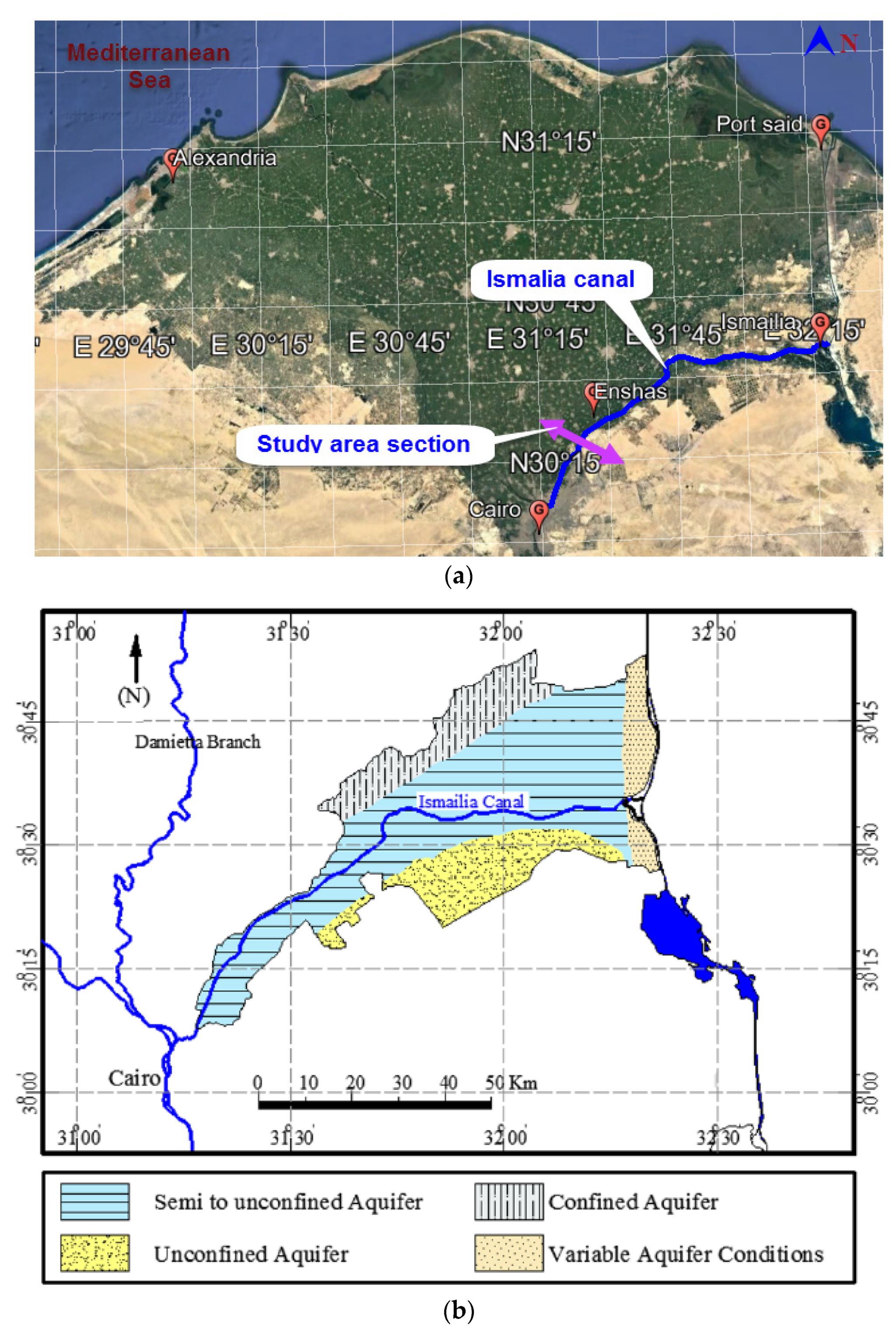
2.1. Case study and Site Investigation

The Ismailia canal is considered one of the most important canals in Egypt, it starts near Cairo, has an total length of 129 km, and serves about 320,000 ha [5]. In some stretches of the Ismailia canal, severe seepage losses occur, which represent about 20% of the total canal discharge [6]. A site investigation using boreholes was carried out of an Ismailia canal section, of the stretch 28.00–49.00 km, to identify the soil profile, ground water table, and to determine the soil grain size distribution. Figure 2 presents a location map of the study area and the hydrogeology of the aquifers, for confinement of the quaternary aquifer.
Soil grading is considered a main feature governing soil permeability, which in turn governs the soil hydraulic conductivity. The studied soil was classified as sandy soil with a trace of silt, based on the unified soil classification system (USCC). The first meter of the soil profile from the ground surface was silty clay deposits, and the ground water table was at a depth of 3 m below the ground surface.

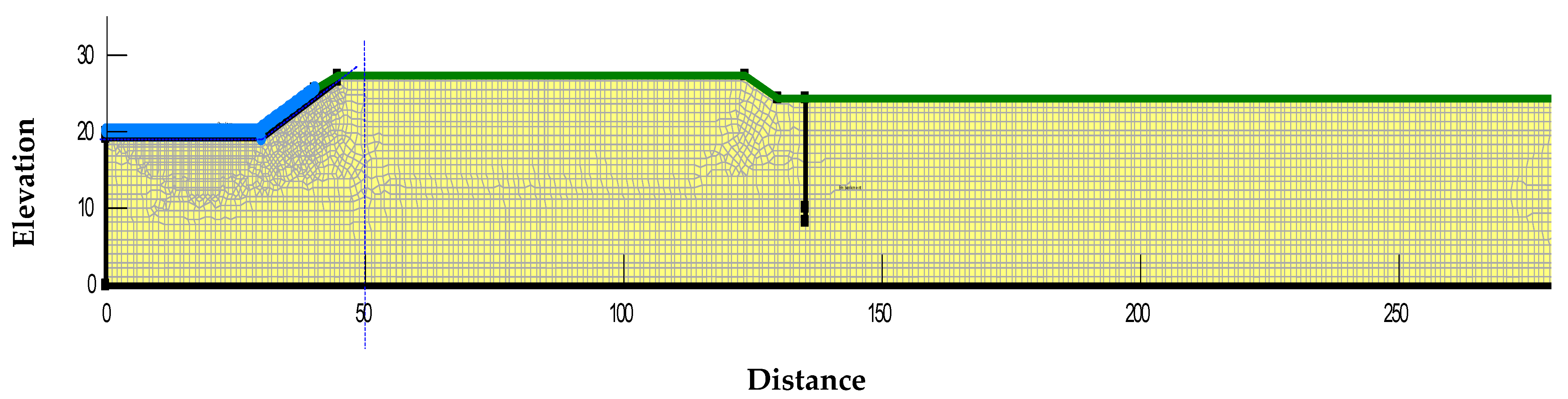
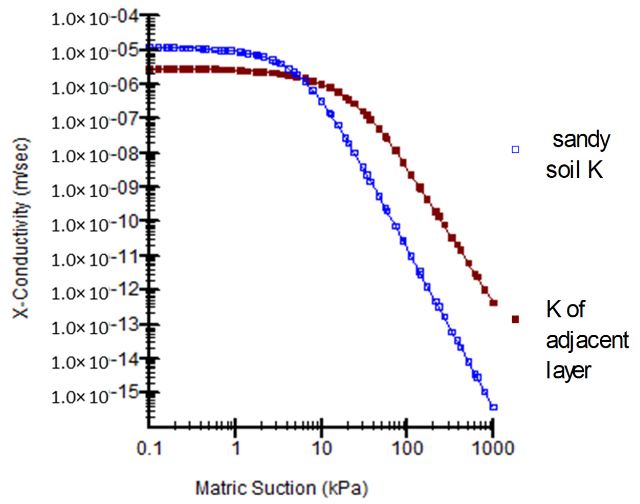
2.2. Numerical Modelling

Based on Darcy’s law and a continuity equation, the two-dimensional partial differential Equation (1) governs seepage through porous media. Due to the analytical solution difficulty of this equation, a numerical solution based on a finite element approach was used to solve the governing equation using seep/w [28]. Figure 3 indicates the seep/w numerical model of the studied section (the stretch from 28.00 to 49.00 km), with a canal bed width of 59 m and 2:1 side slope. Based on the soil report, the studied section consists of sandy soil with a trace of silt as the main soil type and a thin lined band of silty clay deposits. The hydraulic properties for the main and thin liner band soil are shown in Figure 4. It was assumed that the soils are isotropic and homogenous, and the different lining materials were defined as an interface with the determined hydraulic conductivity. The boundary conditions of the seep/w model were defined as the ground water table being at 3.0 m below the ground surface and the canal water levels fluctuating between 12.4 m and 13.1 m, corresponding to the minimum and maximum discharges, respectively. To assess the effect of extraction from the aquifer on the canal seepage rate, a well with a determined pumping rate was defined in the numerical model. In the seep/w numerical model, the total head is used to define the boundary conditions. Thus, to simulate the damage that can occur to the lining material, the total head above and below the liner was set as equal, and in such way the cracks in the liner can be represented:
x ( k x   H x   ) + y ( k y   H y   ) +   Q = θ t
where; H is total head; kx is the hydraulic conductivity in the x-direction; ky is the hydraulic conductivity in the y-direction; Q is the applied boundary flux; θ is the volumetric water content; and the time is t.
Table 1 indicates the variables employed in this study. Hydraulic conductivity is considered the key factor in seepage analysis problems. Unfortunately, there is a misunderstanding regarding the soil permeability and soil hydraulic conductivity. The hydraulic conductivity is used to measure how easily water moves through the porous media. It depends on the permeability of the porous media, the degree of saturation, and the density, as well the fluid viscosity, with the dimensions LT−1. While, the permeability is considered an intrinsic feature of soil, which measure how well a porous media can transmit a fluid, independently from the fluid itself. It measures the ability of a porous material to allow fluids to pass through it, with the dimensions L2.
The soil hydraulic conductivities were defined as a function with matric suction representing different saturation states, as shown in Figure 4. It is worth noting that the maximum value of the hydraulic conductivity is define as the saturated hydraulic conductivity (Ksat) that occur at matric suction near to zero, and then the soil hydraulic conductivity decreases as the matric suction increases. This can be explained as following: the soil hydraulic conductivity decreases as the air content increases in the soil pores, where these pores are partly filled with water; therefore, the available paths for water to flow are limited and discontinuous. While, the hydraulic conductivity increases with increasing water content, reaching the maximum value at soil saturation [29]. As mentioned before, the hydraulic conductivity depends on the soil permeability, so the volumetric water content (θ) is also considered a key parameter and is also represented as a function versus matric suction. The saturated volumetric water content equals the soil porosity; it also decreases as the matric suction increases, until reaching the residual water content. The relation between the hydraulic conductivity and volumetric water content versus matric suction is known as the soil water characteristic curves (SWCCs). It is worth noting that the saturated hydraulic conductivity of a coarse soil has a higher value than that of fine soil; however, at high matric suctions (i.e., low saturated cases), the value of the hydraulic conductivity of a coarse soil becomes less than that of a fine soil. This can be attributed to the discontinuities of the fluid passage and the large number of air voids [29].

3. Results and Discussion

3.1. Seepage Losses for the Earth Canal

A 2-D steady state seep/w numerical software was utilized to simulate an Ismailia canal cross section, at the stretch from 28.00 to 49.00 km, to investigate the impact of using different lining materials on the amount of the water seepage from the earthen canal. The numerical model was established based on the variables presented in Table 1. In order to verify the numerical model, seepage losses were numerically determined and compared with different analytical and empirical methods, as shown in Figure 5a,b, respectively. It can be clearly seen that the amount of water seepage calculated numerically in this study matched closely with both the analytical and empirical solutions of Molesworth and Yennidunia, both in the case of maximum and minimum discharges, which were 0.0106274 and 0.0089846 m3 s−1 km−1, respectively. This observation agree with the recommendations of Mowafy [5] and El-Enany, and El-Alfy [16], regarding the use of this method to determine the seepage loss of earthen canals in Egypt. As expected, the amount of seepage in the case of maximum discharge was slightly higher than that of the minimum discharge; this can be attributed to the defined total head and the wetted perimeter corresponding to each case.
As expected, the seepage losses during maximum discharge of the canal were more than those in the case of a minimum discharge, as indicated in Figure 6. This can be attributed, as mentioned before, to the total head and wetted perimeter. Where, in the case of the maximum discharge, both the wetted perimeter and total head were more than those of the corresponding minimum discharge case. Figure 6 also shows the effect of extraction from the aquifer on the seepage of the earthen canal. As was expected, the amount of water seepage increased dramatically; increasing the ratio by almost 466% and 523% for the maximum and minimum discharge thresholds, respectively. This observation matches closely with Abd-Elhamid et al. [19], in which the water not only seeped freely under the effect of the total heads, but extraction from the aquifer through wells also greatly increased the flow of the water seepage. Therefore, it can be concluded that seepage losses are highly affected by pumping schemes.

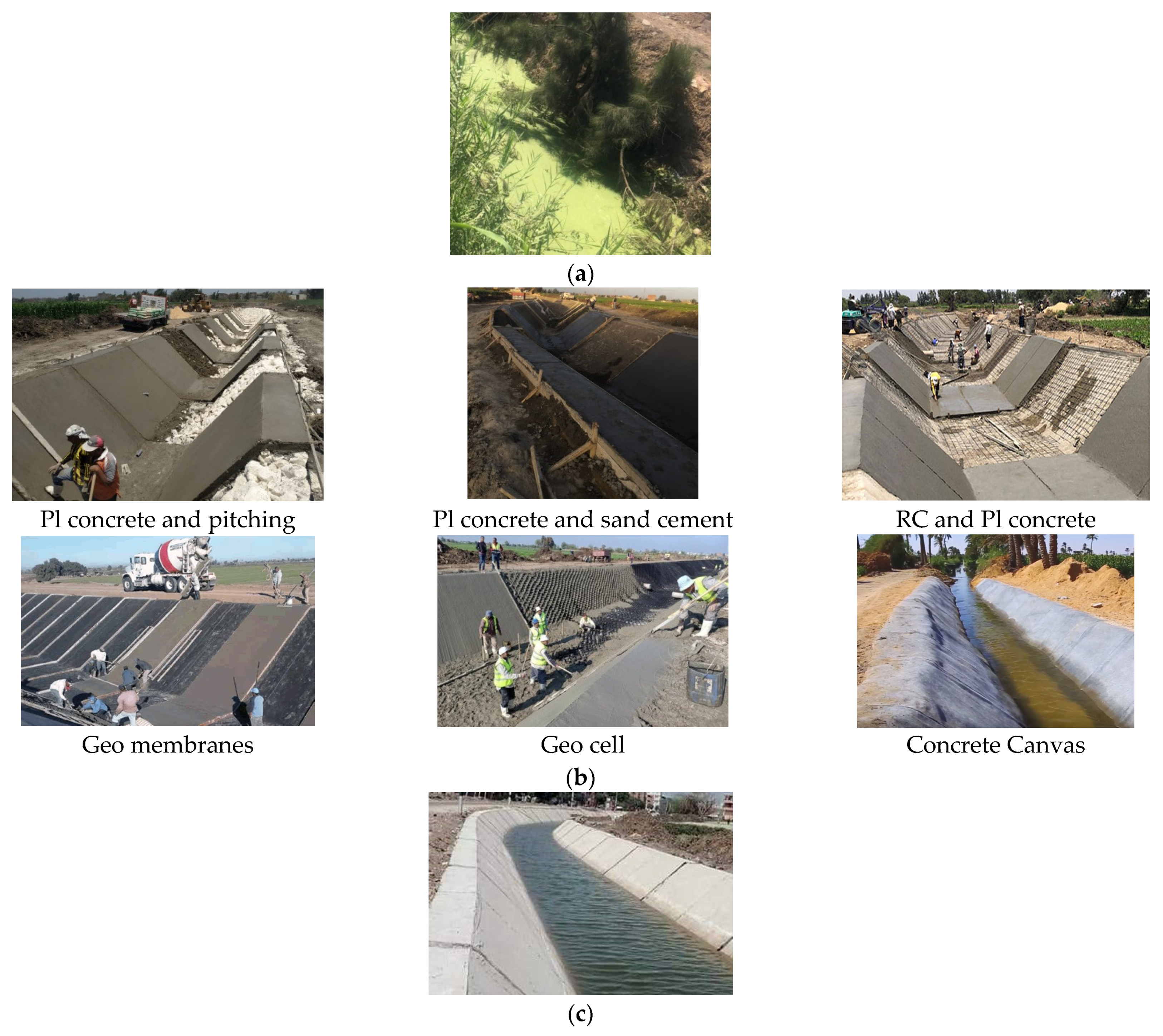
3.2. Seepage Losses from a Lined Canal

The impact of using different lining techniques can be easily observed in Figure 7a, for both maximum and minimum discharge thresholds. Where, the amount of water seepage decreased sharply in the case of using a concrete liner, followed by the geomembrane liner. However, the bentonite liner showed a moderate efficiency, as indicated in Figure 7b. The concrete, geomembrane, and bentonite liner efficiencies were around 99%, 96%, and 54%, respectively. These different efficiencies can be attributed to their different hydraulic conductivities.
Figure 8a depicts the seepage losses during extraction from the aquifer for the different liners studied. As mentioned previously, extraction from the aquifer leads to a dramatic increase of the water seepage, regardless of the canal’s discharge thresholds. However, the use of a lining effectively reduced the seepage of water, as indicated in Figure 8b. Extraction from the aquifer reduced the lining efficiency by almost 4% for the bentonite and geomembrane liners; however, the concrete lining efficiency was not changed considerably. This can reflect the extent to which the concrete lining is more effective. Although the extraction from the aquifer as an external source, increases the rate of water seepage, the lining material effectively resists this external source, thus the seepage rate considerably decreases.

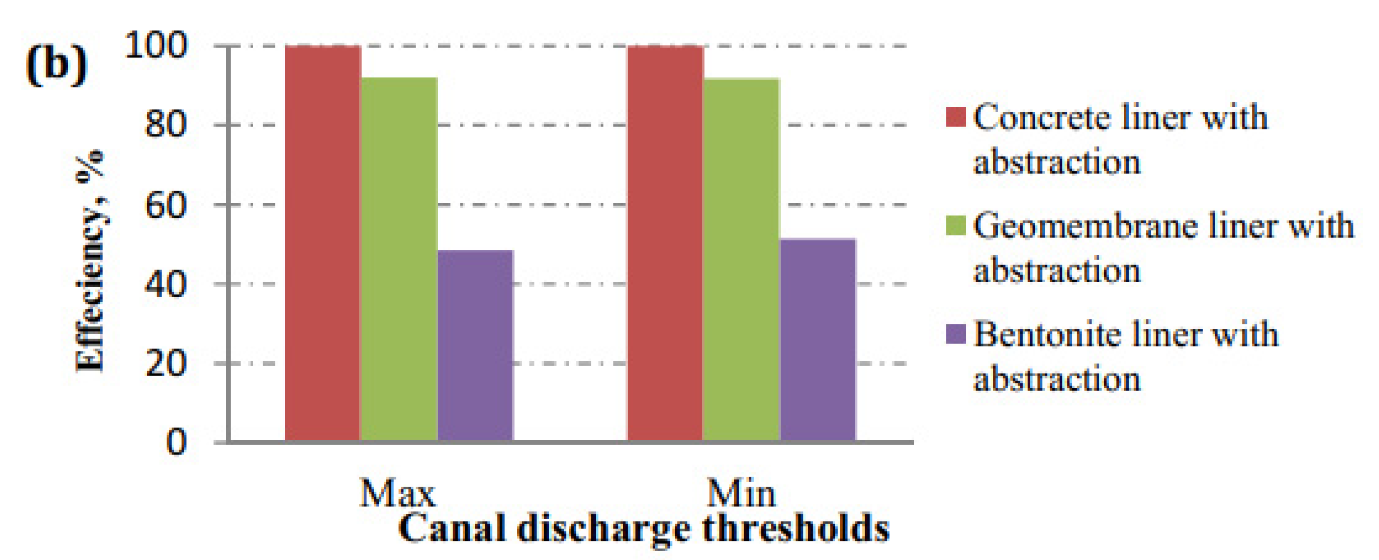
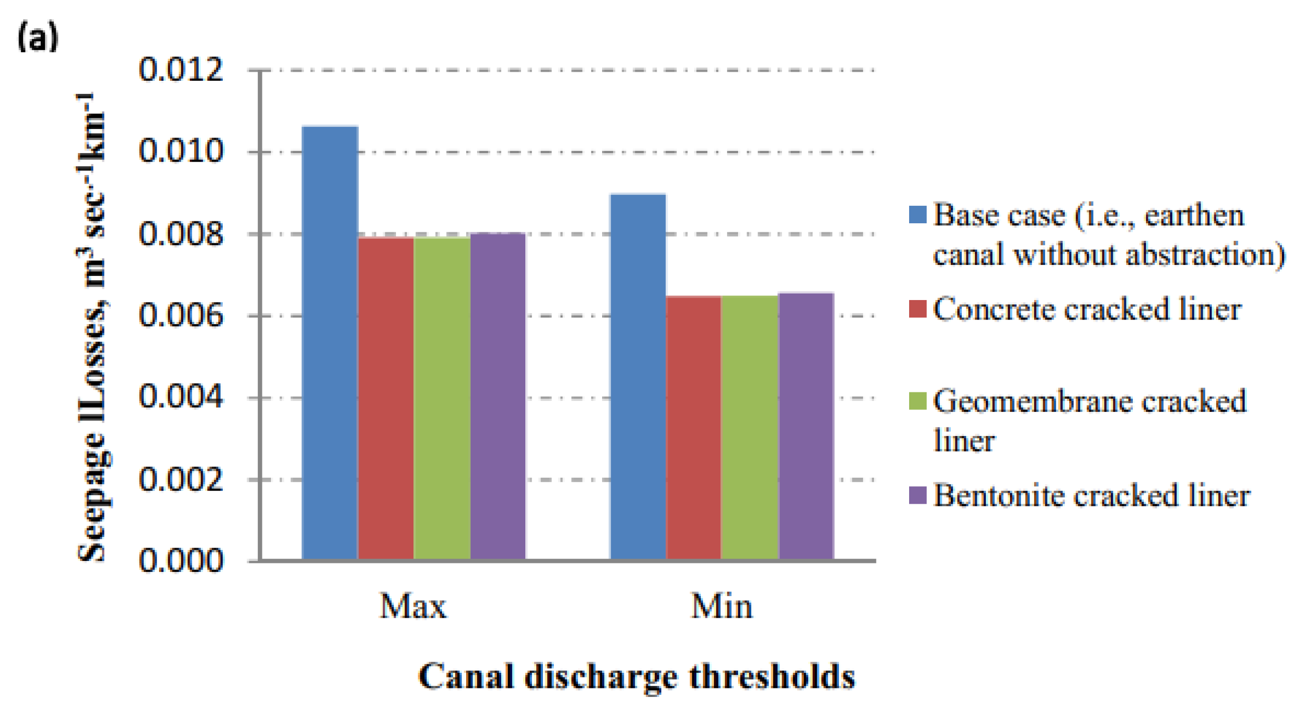
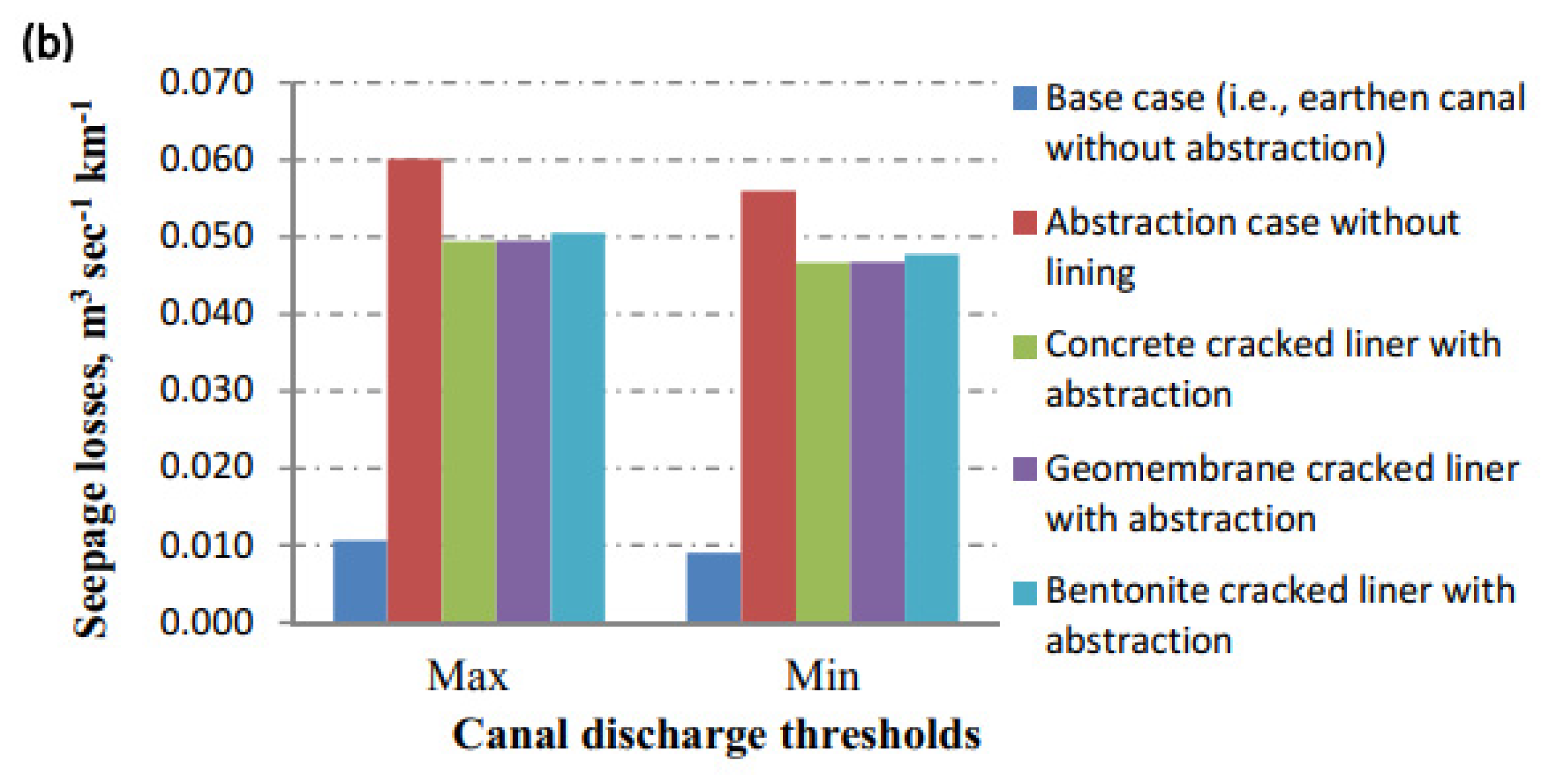
3.3. Seepage Losses from a Cracked Lined Canal

Deterioration of a lining material can occur within a few years, particularly with rigid linings; hence, the seepage can return to that of an unlined canal [9]. To deal with such cases, cracks were simulated using the seep/w numerical model at the point where the canal bed meets the right inclined side of the canal, to investigate the efficiency of different lining techniques after deterioration of the lining material. Figure 9a reveals the canal seepage losses of different cracked liners. The effect of lining material deterioration can be clearly seen, where the lining efficiency significantly decreased, reaching around 25%, regardless of the lining technique (i.e., the lining material). The zone in which cracks were defined to simulate the lining material deterioration showed a rate of seepage much higher than other zones, as shown in Figure 10. Where, the seepage rate is represented by flow vectors, and the size of the flow vector is an indicator of the seepage rate. The effect of extraction from aquifer was also investigated after deterioration of the lining material. As expected, extraction from an aquifer further reduced the efficiency of the liner. The lining efficiency reduced from 25% in the case of a cracked liner to almost 16% with extraction from aquifer, irrespective of the utilized lining technique and canal discharge thresholds, as shown in Figure 9b. This clearly reflects the paramount importance of lining material deterioration, coupled with extraction from an aquifer.

3.4. Cost Analysis for the Used Lining Materials

Egypt has a dense network of waterways, including 33,000 km of irrigation canals and 21,000 km of open drains. The lining of this great length of irrigation canals could improve the water efficiency and requires the selection of lining materials to minimize the construction costs. Abd-Elaty et al. [30,31,32] presented the cost of different lining types for a 25 cm thickness of concrete, geo-membranes with concrete, and mixed bentonite with sand. The study area of the Ismailia canal has a lining perimeter of 86 m and bed width of 59 m, the difference between the berm and bed levels is 6.25 m, with a side slope of 2:1; the high and low water levels are (13.10) and (12.40), while the bed and bank levels are (7.65) and (13.90) for the section at the stretch between 28 + 00 and 49 + 00 km. The calculated costs for the three lining types are presented in Table 2, of which the first is a concrete lining with plain concrete and pitching, plain concrete and sand with cement, and reinforced concrete and sand with cement, giving 18.10, 18.05, and USD 26 for each square meter. The second is geomembrane and plain, geo cell and plain, and concrete canvas and sand, giving 26.40, 22.80, and USD 29.50 for 1.0 m2; these are new types of technology in Egypt. The third is bentonite and compacted soil with a cost of USD 6.30 for 1.0 m2. It is worth mentioning that the cost analysis was estimated based on the Egyptian market price [33,34,35].

4. Discussion

Table 3 presents the results of the numerical model for the seep/w, in which the canal seepage reached 0.0106274 and 0.060172 m3 s−1 km−1 for the base case for the earth material, with and without extraction, for maximum flow. The seepage losses decreased to 1.59 × 10⁷, 3.77 × 10⁴, and 5.06 × 10³ m3 s−1 km−1 for linings with concrete, geomembrane, and bentonite without extraction, respectively. While, the losses reached 6.13 × 10⁷, 8.35 × 10⁴, and 2.06 × 10⁻² m3 s−1 km−1 during extraction. Moreover, cracks occurring in the lining material, due to soil failure or defects in the lining material, increased the canal seepage to 7.91 × 10³, 7.92 × 10³, and 8.01 × 10³ m3 s−1 km−1 without extraction. In the case of extraction, this reached 4.94 × 10², 4.95 × 10², and 5.06 × 10² m3 s−1 km−1, which was the most severe case of seepage loss. For the minimum flow, the canal seepage for the earth material, with and without extraction, was 0.008985 and 0.055996 m3 s−1 km−1 for the base case. The seepage loss decreased when lining with concrete, geomembrane, and bentonite without extraction, to 1.27 × 10⁷, 3.02 × 10⁴, and 4.09 × 10³ m3 s−1 km−1. Meanwhile, it was 5.66 × 10⁷, 7.39 × 10⁴, and 1.85 × 10² m3 s−1 km−1 with extraction. Moreover the canal seepage increased to 6.48 × 10³, 6.49 × 10³, and 6.56 × 10³ m3 s−1 km−1 in the case of cracking of the lining material without extraction, and it reached 4.66 × 10², 4.67 × 10², and 4.77 × 10² m3 s−1 km−1 during extraction.

5. Conclusions

The Egyptian Ministry of Water Resources and Irrigation has started a national project of the rehabilitation and lining of earthen canals, because of the potential negative impacts of GERD and climate changes, in order to reduce seepage losses and have a more efficient water resource management. A two-dimensional seep/w numerical model was employed in this study to simulate a Ismailia canal section at the stretch 28.00–49.00 km, and to investigate the efficiency of three different lining techniques. The effect of lining material deterioration was also investigated, as well as extraction from an aquifer through a well pumping, to help decision makers in making a suitable lining technique selection. Lining efficiency was greatly dependent on the utilized lining technique. The concrete liner was the most efficient, with 99%; followed by the geomembrane liner, with 96%; and with 52% in the case of the bentonite liner. Extraction from an aquifer through well pumping has a considerable impact on the water seepage from earthen canals; however, its impact decreased significantly in the case of lined canals. The deterioration that can occur in lining materials has a considerable impact on lining efficiency, irrespective of the utilized lining technique, where the lining efficiency was reduced to around 25%. The coupled effect of lining material deterioration and extraction from an aquifer led to a reduced lining efficiency, to around 16%, regardless of the utilized lining technique. It is recommended to follow the necessary precautions to prevent cracks in the lining material during the implementation process. Using water-stop seals in the zone where the canal bed meets its vertical sides is also recommended, particularly in the case of using a rigid lining material, to prevent leakage due to potential cracks in the liner material.

Author Contributions

All authors whose names appear on the submission made substantial contributions. Site investigation and soil specimens were brought and prepared for testing by I.A.-E., Numerical simulations and analyses were performed by E.E. The first draft of the manuscript was written by E.E. and I.A.-E.; M.Z. revised and presented suggestive comments about the previous versions of the manuscript. All authors have read and agreed to the published version of the manuscript.

Funding

This work was supported by the Slovak Research and Development Agency under the Contract no. APVV-20-0281. This work was supported by the project of the Ministry of Education of the Slovak Republic VEGA 1/0308/20 Mitigation of hydrological hazards, floods and droughts by exploring extreme hydroclimatic phenomena in river basins.

Institutional Review Board Statement

Not applicable.

Informed Consent Statement

Not applicable.

Data Availability Statement

Data for this work can be found within the article, and for further data feel free to contact the first and corresponding authors.

Conflicts of Interest

The authors confirm that there is no conflict concerning the publication of this manuscript.

References

  1. El-Molla, D.A.; El-Molla, M.A. Seepage losses from trapezoidal earth canals with an impervious layer under the bed. Water Pract. Technol. 2021, 16, 530–540. [Google Scholar] [CrossRef]
  2. Sadek, M.; Hagagg, K. Impact of reduced flow on 137Cs behavior in Ismailia Canal and surrounding groundwater systems. Environ. Sci. Pollut. Res. 2020, 27, 44279–44291. [Google Scholar] [CrossRef]
  3. Abd-Elhamid, H.; Abdelaty, I.; Sherif, M. Evaluation of potential impact of Grand Ethiopian Renaissance Dam on Seawater Intrusion in the Nile Delta Aquifer. Int. J. Environ. Sci. Technol. 2019, 16, 2321–2332. [Google Scholar] [CrossRef]
  4. Waller, P.; Yitayew, M. Irrigation and Drainage Engineering; Springer: Berlin/Heidelberg, Germany, 2015. [Google Scholar]
  5. Eltarabily, M.G.; Moghazy, H.E.; Abdel-Fattah, S.; Negm, A.M. The use of numerical modeling to optimize the construction of lined sections for a regionally-significant irrigation canal in Egypt. Environ. Earth Sci. 2020, 79, 80. [Google Scholar] [CrossRef]
  6. Mowafy, M.H. Seepage losses in Ismailia canal. In Proceedings of the Sixth International Water Technology Conference, Alexandria, Egypt, 23–25 March 2001. [Google Scholar]
  7. Atmapoojya, S.L.; Ingle, R.N.; Kacimov, A.R.; Swamee, P.K.; Mishra, G.C.; Chahar, B.R. Design of minimum seepage loss canal sections. J. Irrig. Drain. Eng. 2001, 127, 189–192. [Google Scholar] [CrossRef]
  8. Wachyan, E.; Rushton, K.R. Water losses from irrigation canals. J. Hydrol. 1987, 92, 275–288. [Google Scholar] [CrossRef]
  9. Plusquellec, H. Overestimation of benefits of canal irrigation projects: Decline of performance over time caused by deterioration of concrete canal lining. Irrig. Drain. 2019, 68, 383–388. [Google Scholar] [CrossRef]
  10. Abd-Elhamid, H.F.; Said, A.M.; Abdelaal, G.M.; Abd-Elaty, I. Impact of polluted open-drain geometry on groundwater contaminant in unconfined aquifers. Arab. J. Geosci. 2021, 14, 432. [Google Scholar] [CrossRef]
  11. Abuzeid, T.S. Conveyance losses estimation for open channels in Middle Egypt case study: Almanna main canal, and its branches. JES J. Eng. Sci. 2021, 49, 64–84. [Google Scholar]
  12. Sarki, A.; Memon, S.; Leghari, M. Comparison of different methods for computing seepage losses in an earthen watercourse. Agric. Trop. Subtrop. 2008, 41, 197–205. [Google Scholar]
  13. Eshetu, B.D.; Alamirew, T. Estimation of seepage loss in irrigation canals of Tendaho sugar estate, Ethiopia. Irrig. Drain. Syst. Eng. 2018, 7, 3–7. [Google Scholar]
  14. Zhang, Q.; Chai, J.; Xu, Z.; Qin, Y. Investigation of irrigation canal seepage losses through use of four different methods in Hetao irrigation district, China. J. Hydrol. Eng. 2017, 22, 05016035. [Google Scholar] [CrossRef]
  15. Singh, S.; Lal, C.; Shahi, N.C.; Chand, K. Estimation of canal seepage under shallow water table conditions. J. Acad. Ind. Res. 2013, 1, 571–575. [Google Scholar]
  16. El-Enany, M.; El-Alfy, K.S.A.E.-W.; Soheib, M.F.; Armanious, S.D.; Gergis, E.S. Modification of the improved irrigation system in the old lands in Egypt. (Dept. C). MEJ. Mansoura Eng. J. 2004, 29, 21–45. [Google Scholar] [CrossRef]
  17. Soothar, R.; Mirjat, M.S.; Mangrio, M.A.; Chandio, A.S.; Leghari, N. Estimating seepage losses in different size of earthen watercourses at farm level. Pak. J. Agric. Agric. Eng. Vet. Sci. 2015, 31, 81–92. [Google Scholar]
  18. Elkamhawy, E. Rehabilitation of Irrigation and Drainage Networks in Sharkia Irrigation Directorate. Master’s Thesis, Zagazig University, Zagazig, Egypt, 2016. [Google Scholar]
  19. Abd-Elhamid, H.F.; Abdelaal, G.M.; Abd-Elaty, I.; Said, A.M. Efficiency of using different lining materials to protect groundwater from leakage of polluted streams. J. Water Supply Res. Technol.-Aqua 2019, 68, 448–459. [Google Scholar] [CrossRef]
  20. Stark, T.; Hynes, J. Geomembranes for Canal Lining; Geosynthetics: Salt Lake City, UT, USA, 2009. [Google Scholar]
  21. Blanco, M.; Castillo, F.; Soriano, J.; Noval, A.M.; Touze-Foltz, N.; Pargada, L.; Rico, G.; Aguiar, E. Comparative Study of Three Different Kinds of Geomembranes (PVC-P, HDPE, EPDM) Used in The Waterproofing of Reservoirs. In Proceedings of the Eurogeo 5, Valencia, Spain, 16–19 September 2012. [Google Scholar]
  22. Ojoawo, S.; Adegbola, A. The system dynamics modeling method in application of geo-membranes as landfill liners. Am. Int. J. Contemp. Res. 2012, 2, 138–144. [Google Scholar]
  23. Abd-Elaty, I.; Zelenakova, M.; Straface, S.; Vranayová, Z.; Abu-hashim, M. Integrated modelling for groundwater contamination from polluted streams using new protection process techniques. Water 2019, 11, 2321. [Google Scholar] [CrossRef] [Green Version]
  24. Available online: https://www.youm7.com/story/2021/6/12/%D8%AD%D9%8A%D8%A7%D8%A9-%D9%83%D8%B1%D9%8A%D9%85%D8%A9-%D8%AA%D8%A8%D8%B7%D9%8A%D9%86-85-%D9%83%D9%85-%D9%85%D9%86-%D8%AA%D8%B1%D8%B9-%D8%A7%D9%84%D8%BA%D8%B1%D8%A8%D9%8A%D8%A9-%D8%AD%D9%81%D8%A7%D8%B8%D8%A7-%D8%B9%D9%84%D9%89/5351354 (accessed on 5 June 2021).
  25. Available online: https://www.geosynthetica.com/geosynthetics-agricultural-water-security/ (accessed on 20 June 2015).
  26. Available online: https://www.elaard.com/87592 (accessed on 15 March 2020).
  27. Sallouma, M.K.M. Hydrogeological and Hydrochemical Studies East of Nile Delta, Egypt. Ph.D. Thesis, Faculty of Science, Ain Shams University, Cairo, Egypt, 1983; 166p. [Google Scholar]
  28. Krahn, J. Seepage Modeling with SEEP/W: An Engineering Methodology; GEO-SLOPE International: Calgary, AB, Canada, 2004. [Google Scholar]
  29. Elkamhawy, E.; Wang, H.; Zhou, B.; Yang, Z. Failure mechanism of a slope with a thin soft band triggered by intensive rainfall. Environ. Earth Sci. 2018, 77, 340. [Google Scholar] [CrossRef]
  30. Abd-Elaty, I.; Said, A.M.; Abdelaal, G.M.; Zeleňáková, M.; Jandora, J.; Abd-Elhamid, H.F. Assessing the impact of lining polluted streams on groundwater quality: A case study of the Eastern Nile Delta Aquifer, Egypt. Water 2021, 13, 1705. [Google Scholar] [CrossRef]
  31. Abd-Elaty, I.; Kuriqi, A.; El Shahawy, A.E. Environmental rethinking of wastewater drains to manage environmental pollution and alleviate water scarcity. Nat. Hazards (Dordr.) 2021, 27, 1–28. [Google Scholar] [CrossRef]
  32. Abd-Elhamid, H.F.; Abd-Elmoneem, S.M.; Abdelaal, G.M.; Zeleňáková, M.; Vranayova, Z.; Abd-Elaty, I. Investigating and Managing the Impact of Using Untreated Wastewater for Irrigation on the Groundwater Quality in Arid and Semi-Arid Regions. Int. J. Environ. Res. Public Health 2021, 18, 7485. [Google Scholar] [CrossRef] [PubMed]
  33. Available online: https://www.alibaba.com/product-detail/Hdpe-Geocell-Hdpe-Geocell-Earthwork-HDPE_60684636819.html?spm=a2700.pccps_detail.normal_offer.d_title.196f7179blSCfI&s=p (accessed on 10 August 2021).
  34. Available online: https://www.alibaba.com/product-detail/Hdpe-Geomembrane-Suppliers-for-Waste-Containment_1600232356483.html?spm=a2700.details.0.0.48d971779Yz4jD (accessed on 10 August 2021).
  35. Available online: https://www.alibaba.com/product-detail/Concrete-Canvas-Cement-Blanket-Concrete-Waterproof1600321346374.html?spm=a2700.galleryofferlist.normal_offer.d_title.69ce7b4eXPOvz6&s=p (accessed on 10 August 2021).
Figure 1. Streams problems and different lining materials. (a) Earth canal without lining. (b) Different lining types [24,25,26]. (c) Irrigation water in lined canals.
Water 13 03135 g001
Figure 2. Location map and hydrogeology of the study area. (a) Study area location. (b) Study area aquifers (Eltarabily, 2020 [5] and modified from Sallouma 1983) [27].
Water 13 03135 g002
Figure 3. Schematic diagram of the numerical model of the Ismailia canal for the stretch 28.00–49.00 km.
Water 13 03135 g003
Figure 4. Hydraulic conductivity functions of the main sandy soil and adjacent clay deposit layer of the canal.
Water 13 03135 g004
Figure 5. Canal seepage losses from the earth canal using (a) analytical formulas, (b) empirical formulas.
Water 13 03135 g005
Figure 6. Canal seepage losses under well extraction.
Water 13 03135 g006
Figure 7. Canal linings of different materials without extraction with (a) seepage losses and (b) efficiency.
Water 13 03135 g007
Figure 8. Canal linings of different materials with extraction for (a) seepage losses and (b) efficiency.
Water 13 03135 g008aWater 13 03135 g008b
Figure 9. Canal seepage losses of different cracked liners, (a) without extraction and (b) with extraction.
Water 13 03135 g009aWater 13 03135 g009b
Figure 10. Seepage losses (a) base case (i.e., unlined canal), and (b) cracked liner.
Water 13 03135 g010
Table 1. Variables employed in this study.
Discharge, m3 s−1CaseKsat, m s−1Well Extraction (0.00236 m3 s−1)Cracks in Liner
Max. discharge 397.12 Base case1.158 × 10−5
Concrete liner4.63 × 10−14
Geomembrane liner1.16 × 10−10
Bentonite liner3.82 × 10−8
Min. discharge 300.48Base case1.158 × 10−5
Concrete liner4.63 × 10−14
Geomembrane liner1.16 × 10−10
Bentonite liner3.82 × 10−8
Table 2. Specifications, quantities, and prices of different lining materials.
ItemLining TypeMaterialVolumePrice ($/m2)Study Area
Thickness (cm)Price ($/m2)
1Plain concrete and pitching Plain concrete1 m379107.90
Pitching without mortar 1 m3343010.2
Total price---18.10
Plain concrete and sand with cement Plain concrete1 m3791511.85
Sand cement1 m331206.20
Total price---18.05
Reinforced concrete and sand with cement Reinforced concrete1 m31981019.80
Sand cement1 m331206.20
Total price---26
2Geomembrane and plain concrete Plain concrete1 m3792015.80
Sand cement1 m331206.10
High-density ploy ethylene geomembrane1 m24.500.104.50
Total price---26.40
Geo cell and plain concrete Plain concrete1 m3792015.80
High-density geo cell1 m270.107
Total price---22.80
Concrete canvas and sand Sand1 m37.50201.50
Concrete canvas1 m228128
Total price---29.50
3Bentonite and compacted soil Compacted soil1 m39302.70
Bentonite1 m318203.60
Total price---6.30
Table 3. Results of canal seepage with a lining and cracks, considering extraction.
Discharge,
(m3 s−1)
CaseWithout Extraction
(m3 s−1 km−1)
With Extraction
(m3 s−1 km−1)
Max. discharge 397.12 Base case0.01062740.060172
Concrete linerWithout crack1.59 × 1076.13 × 107
With crack7.91 × 1034.94 × 102
Geomembrane linerWithout crack3.77 × 1048.35 × 104
With crack7.92 × 1034.95 × 102
Bentonite linerWithout crack5.06 × 1032.06 × 102
With crack8.01 × 1035.06 × 102
Min. discharge 300.48Base case0.0089850.055996
Concrete linerWithout crack1.27 × 1075.66 × 107
With crack6.48 × 1034.66 × 102
Geomembrane linerWithout crack3.02 × 1047.39 × 104
With crack6.49 × 1034.67 × 102
Bentonite linerWithout crack4.09 × 1031.85 × 102
With crack6.56 × 1034.77 × 102
Publisher’s Note: MDPI stays neutral with regard to jurisdictional claims in published maps and institutional affiliations.

