
A Review on Promising Membrane Technology Approaches for Heavy Metal Removal from Water and Wastewater to Solve Water Crisis


1
Chemistry Department, Faculty of Science, Alexandria University, Alexandria 21526, Egypt
2
Department of Chemistry, College of Science, Qassim University, Qassim 52571, Saudi Arabia
3
Arab Academy for Science, Technology and Maritime Transport, Alexandria 1029, Egypt
*
Author to whom correspondence should be addressed.
Water 2021, 13(22), 3241; https://doi.org/10.3390/w13223241
Submission received: 1 September 2021
/
Revised: 16 October 2021
/
Accepted: 19 October 2021
/
Published: 16 November 2021
(This article belongs to the Section Water Use and Scarcity)
Abstract
:Due to the impacts of water scarcity, the world is looking at all possible solutions for decreasing the over-exploitation of finite freshwater resources. Wastewater is one of the most reliable and accessible water supplies. As the population expands, so do industrial, agricultural, and household operations in order to meet man’s enormous demands. These operations generate huge amounts of wastewater, which may be recovered and used for a variety of reasons. Conventional wastewater treatment techniques have had some success in treating effluents for discharge throughout the years. However, advances in wastewater treatment techniques are required to make treated wastewater suitable for industrial, agricultural, and household use. Diverse techniques for removing heavy metal ions from various water and wastewater sources have been described. These treatments can be categorized as adsorption, membrane, chemical, or electric. Membrane technology has been developed as a popular alternative for recovering and reusing water from various water and wastewater sources. This study integrates useful membrane technology techniques for water and wastewater treatment containing heavy metals, with the objective of establishing a low-cost, high-efficiency method as well as ideal production conditions: low-cost, high-efficiency selective membranes, and maximum flexibility and selectivity. Future studies should concentrate on eco-friendly, cost-effective, and long-term materials and procedures.
1. Introduction
Fresh water resources (H2O) are used in all areas of life. Water pollution is a major issue related to human health, and it circulates widely and causes water shortages. The desalination of seawater and brackish water is the best choice to overcome water problems [1]. Intense industrial progress, energy engineering, agriculture, and public utilities have increased water use rates, and new technologies need to be found to improve water quality. The treatment plant must provide a flow chart that complies with the latest standard specifications for H2O supply [2]. The preparation of drinking H2O and obtaining zero-charge H2O requires several treatment steps: the electrochemical condensation of H2O after the slow sand filtration process is used as a biological process to remove pathogens in drinking H2O. The chemical processes involved in H2O drinking include the formation of dissolved oxidative pollutants. The precipitate is removed by filtration and coagulation. The sedimentation removes most of the solids by gravity and reduces the solid load in the downstream filtration process [3]. The physical process involves flocculation, adsorption and disinfection with ultraviolet rays and ozone. Electrochemical demineralization effectively removes heavy metal ions in water [4].
The goal of wastewater treatment (sources, Figure 1) is to reduce/remove inorganic and organic components, harmful chemicals, kill pathogenic bacteria, and so on [5,6,7]. As a result, the quality of treated water is improved to satisfy the criteria of WHO guidelines or an individual country’s pollution control body. Pollutants in municipal and industrial wastewater vary depending on location [8,9]. As a result, the forms of wastewater treatment are determined by the nature of the wastewater and the necessary quality of water after treatment.
Wastewater treatment typically consists of three stages [10]: primary, secondary, and tertiary (Figure 2). The primary and secondary treatment processes, respectively, are employed to remove the bulk of big particles and organic waste. After the primary and secondary treatments, certain unwanted materials remain in the treated water; the tertiary treatment acts as a polishing unit to eliminate such matter. In most cases, these therapies include a mix of physical, chemical, and biological activities [11].
1.1. Primary Treatment Processes
This procedure (Figure 3) consists of two sequential steps: preparatory treatment and sedimentation [12,13]. Screening, grit chambers, and skimming tanks are used in preliminary treatment to remove big particles and debris from wastewater, oil, and fats. In addition, the wastewater is sedimented or chemically precipitated in primary settling tanks, which eliminates organic solids, colloidal and finer suspended particles as sludge.
1.2. Secondary Treatment
Biodegradable soluble organic molecules are degraded by microorganisms during the secondary treatment process (Figure 4) [14]. In the presence of oxygen, suitable microorganisms feed on the wastewater, expanding their population by devouring organic matter as feed. In general, biochemical oxygen demand (BOD) is employed as a wastewater measurement parameter; when organic matter is eliminated, the BOD level falls [15]. This biological unit process is further subdivided into two types: suspended growth systems and attached growth systems. The wastewater circulates around and through the free-floating microorganisms in the suspended growth system, forming biological flocs that sink at the bottom. The settling flocs contain microorganisms that are recycled back into the wastewater treatment process. Suspended growth systems include activated sludge processes and aerated lagoons. Attached-growth processes, on the other hand, employ media such as a fixed bed of gravel, ceramic, or plastic media to hold and grow microorganisms. The wastewater runs over the media, forming a biofilm that thickens with growth and falls or is removed as sloughing. The same is true for trickling filters and rotating biological contactors (RBC).
When compared to suspended-growth systems, attached-growth procedures are easier to operate, needless equipment maintenance, and use less energy. At the same time, it requires more room, has odor concerns, and is limited in its ability to manage big volumes of wastewater.
1.3. Tertiary Treatment
Tertiary treatment methods are sometimes referred to as advanced treatment approaches [16]. This process eliminates a significant amount of phosphorus, nitrogen, biodegradable organic waste, heavy metals, viruses, and pathogenic bacteria [17,18]. Disinfection, membrane separation, and electrodialysis are some of the most advanced therapeutic procedures that have been developed. Table 1 summarizes the benefits and drawbacks of conventional wastewater treatment as well as tertiary treatment.
The screening and degreasing of highly polluted H2O to remove bulk materials and the coagulation and flocculation of suspended colloidal particles are the prerequisites for the liquid separation process. Other pretreatment methods include oxidation to remove excess organics and pathogens, insecticide, and heavy metal ions [19]. Flocculation is used in many industries, such as mineral extraction, chemical industry, food processing industry, and drinking water H2O treatment to improve the separation of solids and liquids through filtration using sand beds or activated carbon inorganic adsorbents to maintain the quality of H2O, but they really cannot solve all the problems. Chemical coagulation is carried out before MF. Iron-based coagulant and clay coagulant are used to improve the turbidity and the pretreatment of NOM H2O total suspended solids [20]. Calcium chloride (CaCl2) added to the humic acid (HA) solution intensifies HA through charge neutralization, complexation, and bridging. Polyacrylamide (PAAm) is a common flocculant. Flocculation improves the recovery rate of the process water and reduces the amount of sludge [21]. The surface of the open pond system that is settling can be exchanged with the nearby aquatic environment. For example, water seeping into the ground, the leakage of H2O from natural streams can cause flocculants to diffuse into surface and groundwater. Potential environmental hazards do not involve degradation products of PAAm, and residual monomers contained in the flocculants due to the incomplete polymerization process. In some studies, acrylamide is reported to be a neurotoxin for humans, classified as carcinogenic, mutagenic, and as a toxic compound. Polyacrylamide PAAms are water-soluble molecules. High molecular weight PAAms (106–107 g·mol−1) are used as flocculants, leaving a transparent supernatant for subsequent solid and liquid separation. Compared with the cationic form, the anionic form of PAAm has very low aquatic toxicity, so it is not harmful to the environment. The most valent anion, PAAm, contains about 30 moles of acid molecules that crosslink when dissolved in water. These molecules are nominally linear, although they may curl or curl to varying degrees due to chain substitution or the effect of electrolytes in water. All types of PAAm contain a certain degree of residual acrylamide monomer, depending on the degree of polymerization. The PAAm used to treat drinking H2O does not contain more than 0.05% of residual acrylamide. The fate of PAAm and related residual acrylamide in the water system limits the use of PAAm as a flocculant because its solubility in H2O is, unlike Absorb organic and inorganic components from the soil. The leaching potential and H2O pollution in the soil are the main environmental risks associated with the use of PAA [22].
Electrocoagulation (EC) pretreatment is applied to saltwater solution to eliminate natural organic matter (NOM) by reducing the coagulation pH value and increasing the contact time between the coagulant and NOM, (pH 5.5, current density (J) 10 mA/cm2), the dose is 25 mg aluminum ion/L). If a direct current is passed through the wastewater solution, EC is accompanied by electrophoresis: the dispersed phase moving to the opposite electrode loses charge, and deposits and separates from the solution. During the electrolysis of water, the salt concentration hardly changed. At the end of the process, the alkalinity increased from pH 7.1–7.7, which must be adjusted [23]. EC water treatment was initially purified by removing Fe2+ ions, Ca2+ ions and organic impurities. EC was improved by adjusting the experimental conditions: anode/(cathode) area ratio, current density, anode type (aluminum, steel) and cathode (Pt or graphite) volume or nanometer level) and the position of the positive and negative electrodes. Whether it is parallel or perpendicular, it will affect the efficiency of the current. Due to chloride ion-assisted pitting corrosion, the high salt content of the feed H2O leads to the dissolution of aluminum, and the high concentration of SO4−2 ions further aggravates this dissolution. EC microfiltration (MF) pretreatment can remove hydrophilic NOM residues: polysaccharides and polyamides) as well as hydrophobic NOM and nanocolloids. The Donnan effect largely rejects SO4−2, Ca+2, Mg+2, Sr+2 ions. (J = 10 mA/cm2) is used for aluminum and iron anodes to maximize NOM control and minimize electrolysis time [24].
Common methods to remove heavy metals such as Cu2+ and Ni2+ from industrial water include chemical precipitation, ion exchange, cementation, coagulation and adsorption. While reverse osmosis (RO) is used to remove NaCl. The Locations of H2O on earth depicted in Figure 5 while the progress of the water reclamation cost from different sources is shown in Figure 6. Salty H2O feed (brackish water/seawater/groundwater), low salinity products of H2O, and very salty H2O were removed. Desalinated water is suitable for most household, industrial and agricultural uses. Various organic and inorganic membranes include mixing membranes such as polyvinyl alcohol and PVAsago starch recovered ethyl acetate. The bioreactor FO cellulose triacetate membrane removes 98% of organic carbon and 90% of ammonium nitrogen; polymeric ceramic membranes (zeolite-coated ceramic films and catalytic nanoparticles, hybrid organic-inorganic nanocomposite membranes and biofilms such as hybrid protein-polymer biomimetic membranes, zeolite and catalytic films) are reasonably removed from commercial practice and yield improvements of a low-to-moderate performance [25].
Environmentally friendly ion exchange membranes (IEM) are employed in the electrodialysis (ED) method to demineralize, concentrate, and alter products while maintaining the energy conserved. Fouling from colloidal, organic, scaling, and biofouling reduces process efficiency and raises process costs. Natural, processed H2O and many effluent streams contain colloidal fouling in the form of clay minerals, colloidal silica, (Fe, Al, Mn) oxides, and organic colloids [27]. The main colloidal particles in natural H2O are small aluminum silicate clays. The colloidal particles with opposite charges are attracted to the solution, forming an electric double layer on the surface of the colloidal particles to prevent coagulation. The organic pollutants (oil, carbohydrate, protein, aromatic hydrocarbon, HA and defoamer) in the wastewater dissolved in the solution are also treated with ED [28].
Various suspended molecular weight organic colloids/flakes removed by the pretreatment of the feed solution are used in the ED operation. Almost all feed solution filtration in ED systems will remove particles. However, depending on the nature of the feed solution and the required H2O quality, flocculation, metal hydroxide precipitation and ion exchange are required. Negatively charged particles or big organic anions move and deposit on the anion exchange membrane (AEM) when an electric field (E) is applied to the feed solution. The pulsation of the electric field with the best frequency improves the electrophoretic movement of the charged particles [29].
RO can remove clay, iron oxide, silica particles, macromolecular proteins, polysaccharides, and organic matter (OM) and colloidal polysilicic acid in the size range of 1–1000 nm, as well as bacteria and viruses (biocolloids). However, RO desalination has no clear limits. Although better seawater quality is achieved through advanced RO membrane treatment, neither the membrane nor the traditional pretreatment can guarantee the complete removal of NOM. Organic matter in feed (OM) RO: Natural NOM; Algae organic matter (AOM) is composed of extracellular and intracellular macromolecules; and OM wastewater effluent is composed of NOM matrix and soluble microbial products. In addition to the complex macromolecular products that affect the quality of H2O and the chemical and biological degradation of animal and plant residues combined with inorganic ions, NOM also exists in surface H2O, underground, and in seawater composed of humic acid substances [30].
Forward osmosis (FO) of the therapeutically efficient organic and inorganic contaminants of the perforated H2O residues with ignored membrane compliance that can be washed with reversion to restore H2O flow, recover more than 80% H2O. A common composite membrane used in RO is a thin film of PA [31]. In addition to the hollow fiber membrane of the polymeric ethylene (PTFE) polymer. In the RO operation, OM is pretreated by O3 species, OM is oxidized in combination with ceramic filtration, and the contamination of the membrane is controlled to reduce the cleaning agent. As an example, in the drinking water, the Pb2+ allowed are 2 mg L−1 and 10 μm L−1, respectively. These ions should be recycled with sludge, rainfall, extraction of solvents, membrane technology. Membrane faces: Economic, environmental, and technical restrictions that limit its use. The sorption processes that are used efficiently to treat lean emissions require small spaces and often, effectively eliminate metals to the permitted limit. However, the high temperature treatment and activation of carbonization and activation of activated carbon must resolve the difficulty of separating the adhesion of the sorbents used from treated water. Low-cost and efficient biosorbents were developed using rich and renewable marine resources and environmentally friendly. The biomass of agricultural waste algae, the shells of crustaceans and resources are alternatively bio-adsorbent [32].
2. Removal of Heavy Metals
As a result of fast growth, several environmental issues have developed. Because of its high toxicity, non-degradability, and carcinogenic properties, heavy metal ion pollution of water is of special concern [33]. Toxic metal ions, such as cobalt (Co), copper (Cu), nickel (Ni), cadmium (Cd), and lead (Pb), have a high mobility in the aquatic ecosystem. As a result of the food chain, they can readily accumulate in living creatures [21]. Humans face a variety of health hazards because of this [34]. Long-term consumption of contaminated water, for example, can harm internal organs in the human body and cause a variety of diseases, even at trace levels, which is why metal ions in drinking water have such low permissible values (e.g., 0.005 mg L−1 for Cd, 0.01 mg L−1 for Pb, 0.02 mg L−1 for Ni, 1.0 mg L−1 for Cu and Co) [35,36]. A number of techniques have been proposed for this aim. As a result, effective metal ion removal from water is important. A variety of techniques have been proposed to achieve this goal. Figure 7. Represents a Schematic diagram of the filtration spectrum of related separation processes and separated components
2.1. Pressure-Driven Membranes for Heavy Metal Removal
2.1.1. Low-Pressure Membranes
Ultrafiltration (UF) membranes are physical sieving processes that remove solutes based on membrane pore size (5–20 nm) and solute molecular weight (1–100 kDa) [38,39]. The major benefit of UF is its low operating pressure. Because of the low pressure of UF, space needs are reduced, as are energy consumption and capital expenses [40,41]. Despite this, because to its comparatively high pore size, UF cannot be used directly to extract heavy metals from wastewater. As a result, complexing agents or membrane modification may be required. The addition of charged groups to the UF membrane may be an option for increasing the rate of heavy metal recovery. Metal ion separation by charged UF membranes is caused by ion repulsion by the fixed charge groups on the membrane skin. This technique attempts to offer a high-water flow and high heavy metal removal efficiency. Nonetheless, research on charged UF for heavy metal removal is in in its early stages. Yao et al. [42] produced two novels positively charged UF membranes to improve the performance of the UF membrane in Cr6+ removal: a tertiary amine-based UF membrane (TA membrane) and a quaterized TA membrane. The first membrane was created by combining polyvinylidene fluoride (PVDF) and a tertiary amine-containing block copolymer polymethyl methacrylate-b-dimethylamino-2-ethyl methacrylate. A nonsolvent induced phase separation technique was then used to construct the blended material to the TA membrane. Meanwhile, the second membrane was created by surface quaternization of the TA membrane. The results revealed that these two charged UF membranes were capable of rejecting Cr6+ completely.
Micellar-Enhanced Ultrafiltration (MEUF)
MEUF has been presented as a viable approach for circumventing the constraints of UF in heavy metal removal. It has been used to remove different heavy metals from wastewater. MEUF’s fundamental idea is to enhance the molecular size of metal ions by adding surfactants [40,43]. The addition of a surfactant to wastewater increases metal ion complexation with the surfactant. Surfactant molecules will bind to one another, creating micelles, which are huge molecular aggregates. Ionic or hydrophobic interactions tend to absorb metal ions in the structure of the micelles [40,44]. Because of their high molecular size, micelles are easily eliminated when passing over the UF membrane, but unbound metal ions and surfactant monomers can breach the UF membrane and exit into the permeate stream, as illustrated in Figure 8.
MEUF surfactants are typically amphiphilic compounds with a hydrophobic chain and a hydrophilic head group. To produce an ion-pair complex in the application of heavy metal removal, an ionic surfactant with the opposite charge to the metal ion is required [44]. Anionic surfactants, including sodium dodecyl sulfate [46,47,48,49], and sodium dodecyl benzonate sulfonate [50,51], have been widely used for cationic heavy metal removal. Meanwhile, cationic surfactants, including cetylperidinium chloride (CPC), cetyltrimethyl ammonium bromide [52,53], and octadecylamine acetate [54], could be utilized to remove anionic heavy metals. Aside from the kind of surfactant, the concentration of the surfactant has a significant impact on the MEUF efficacy. When the surfactant concentration falls below the critical micellar concentration (CMC), micelles do not form, and the surfactant remains a monomer that can easily penetrate the UF membrane pores [55]. By gradually increasing the concentration of surfactant up to the CMC, the micelle will gradually form and provide sites for the metal ions to attach. However, increasing the surfactant concentration causes micelles to break down into smaller molecules, resulting in a decrease in metal removal efficiency. According to research published by Baek et al. [56], raising the concentration of the surfactant CPC improved chromate elimination. It is consistent with the findings of Baek and Yang [57], who found that increasing the molar ratio (nitrate: chromate: CPC) from 1:1:3–1:1:5 to 1:1:10 improved nitrate removal from 56% to 78% and 89%, respectively. When the CPC concentration was too high; however, the chromate removal was reduced owing to a rise in Cl ions in the solution. The MEUF process’s removal efficiency is additionally impacted by the solution’s operating pressure, pH, and temperature. Several investigations [58,59,60] found that raising the pressure caused an increase in the micelle aggregation layer on the membrane surface, which enhanced heavy metal removal. Table 2. Show the performance of MEUF in heavy metal removal [45].
The increase in pH also increased metal removal. Juang et al. [61] found that increasing the pH from 2 to 12 increased the removal of cationic heavy metals such as Co2+, Cr3+, Cu2+, Mn2+, and Zn2+ by more than 80%. Xu et al. [65] obtained a similar result, increasing the pH from 3 to 11 and increasing the cadmium removal from 83–99%. Meanwhile, heavy metal removal decreased as temperature increased due to demicellization because of micelle palisade layer disruption [43]. As the temperature rose, surfactant ions began to detach from the micelle, allowing more surfactant monomers to pass to the permeate side [54]. The disadvantage of MEUF is the generation of a secondary pollutant when the complexations of the metal-surfactant are not properly treated. As a result, further separation of metal ions from the micelle has emerged as a concern in MEUF processes. Kim et al. [66] successfully recovered 95% of Cd and Cu by adding nitric acid, sulfuric acid, and hydrochloric acid to the MEUF retentate. Chelating agents can also be added to the retentate solution to create a complexation with metals. A subsequent UF process separates the chelating agent and metals from the solution. The addition of iminodiacetic acid, ethylenediaminetetraacetic (EDTA), and citric acid, respectively, resulted in Cu recovery rates of 82.5%, 99.9%, and 100% [66].
Polymer-Enhanced Ultrafiltration (PEUF)
Several researchers have developed PEUF as a method for removing heavy metals from wastewater. PEUF’s principal is like MEUF’s. PEUF, on the other hand, uses a water-soluble polymer to form a complexation with metal ions, resulting in a macromolecule with a high molecular weight. As shown in Table 3, polymers such as polyethyleneimine (PEI) [67,68,69,70], polyacrylic acid (PAA) [67,68,71], poly (acrylic ac-id-co-maleic acid) (PAM) [72], polyvinyl amine (PVAm) [73], and poly (ammonium acrylate) [74] have been used as complexing agents in PEUF to recover various types of heavy metals. PEUF has the advantages of high removal efficiency combined with high binding selectivity, resulting in concentrates containing highly concentrated metal. According to Qiu et al. [72], the use of a complexing agent composed of a copolymer of maleic acid and acrylic acid in PEUF was capable of removing more than 99% of Cu2+, Zn2+, Ni2+, and Mn2+. Meanwhile, the addition of PVAm as the polymeric agent in PEUF could reject 99% of Pb2+ and Fe3+ [73]. The removal efficiency of heavy metals in PEUF processes is affected not only by the type of metal and polymer, but also by the polymer-to-metal ratio and pH [72,75]. According to Qiu et al. [72], increasing the polymer-to-metal ratio improved heavy metal ion removal efficiency. Cu2+, Zn2+, Ni2+, and Mn2+ rejection rates of 99.8%, 98.8%, 99.0%, and 99.6% were obtained with polymer/metal ratios of 6, 7, 7, and 6, respectively. Meanwhile, Barakat and Schmidt [75] found that metal rejection was more efficient at neutral and higher pH than at lower pH. At higher pH, metal ions bind more strongly to polymeric ligands, whereas at lower pH, the polymeric ligands’ affinity for metal ions is weak. This is due to the presence of positive charges as well as the low stability of the complexion metal-polymer at low pH. The affinity and stability of metal-polymer complexes would increase as the pH increased.
The development cost of membrane filtration and desalination technology is low, and it can separate suspended or dissolved components in wastewater. Membrane is a physical barrier that can pass through them based on the physicochemical properties of certain compounds. The membrane consists of a porous support layer and a thin and dense top layer [76]. Pore size-based membrane filtration-ultrafiltration (UF) removes extremely tiny particles and dissolved molecules from fluids based on molecular size; however, the permeability of the filter medium is modified by its chemical, molecular, or electrostatic characteristics in all filtration applications. For a sample of water, UF can only separate molecules whose size differs by at least one order of magnitude. UF cannot separate molecules of similar sizes. Materials with molecular weights ranging from 1 kDa to 1000 kDa, as well as colloids and particles retained by certain UF membranes, are passed through by salt and H2O. The UF membrane cleans the material that passes through the filter and collects the material that the filter retains. Substances that are substantially smaller than the pore size pass through the filter, but substances that are much bigger than the pore size are held by the filter and can be concentrated or separated from low molecular weight pollutants. UF is used for separating proteins from buffer components for buffer exchange, desalting or concentration, removing or exchanging sugars, non-aqueous solvents, separating free from protein-binding ligands, removing low molecular weight materials, or rapidly changing environmental ions and the pH value depends on the protein to be retained, and the most commonly used membranes have a nominal molecular weight limit (NMWL) of 3–100 kDa. UF is more effective than precipitation because it can concentrate and dilute solutes at the same time, without phase change, which denatures unstable substances, and can be carried out at room temperature or lower [77].
Microfiltration (MF) removes particles/biological entities in the range of 0.025 μm to 10.0 μm from the fluid through a microporous membrane filter. Although non-membrane or deep-layer materials (such as those found in fibrous media) can be used to remove micron-sized particles, only membrane filters with precisely defined pore sizes can ensure quantitative retention. Membrane filters can be used for final filtration or pre-filtration, while the depth filter is used in clarification applications that do not require quantitative retention or as a pre-filter to extend the life of downstream membranes. When used together in a MF process system, membrane filters and depth filters complement each other. The retention limit defined by the membrane filter can also be used to quantitatively verify the integrity and efficiency of the system. Fluids containing bacteria, for example, can be filtered to trap microorganisms on the membrane’s surface for further culture and examination, in addition to filtering for clarity or sterilizing. MF can also be used to remove intact cells and some cellular debris from lysates during sample preparation. For these sorts of separations, the cutoff values for membrane pore size are in the range of 0.05–1.0 µm [78].
2.1.2. High-Pressure Membranes
Nanofiltration (NF) is a pressure-driven membrane that operates between UF and RO (RO). It is primarily made of synthetic polymers that are negatively charged on the surface and is thus capable of dissociating heavy metals [79]. As a result, the removal mechanism in NF combines the rejection of uncharged components via a sieving mechanism with electrical (Donnan) interactions between metal ions in solution and the membrane [41,80]. NF has higher rejection of multivalent metal ions than UF, as well as higher water permeability and lower operating pressure than RO [81,82]. It is thought to be an energy-efficient process for heavy metal removal. Table 4 summarizes several commercially available NF membranes that have been used to remove various types of heavy metals. Most commercial NF membranes can remove more than 90% of heavy metals. Merwe [83] classified rejection in NF into three distinct phenomena: (a) rejection of multivalent anions, (b) rejection of cations, and (c) size-based rejection. NF can remove multivalent anions such as sulphate (SO42−) to a high degree (95–99%) [84], whereas monovalent anions such as chloride ion (CI−) are typically rejected at a rate of 5–45% [85,86]. This is because the negative charges of multivalent anions have a strong electrical repulsion with the negative charge on the membrane surface [87]. When cations are associated with multivalent anions to maintain electroneutrality, the rejection is high. When sodium is associated with sulphate, for example, it is rejected to roughly the same extent as the sulphate ion [88]. Uncharged dissolved materials and some positively charged ions, on the other hand, may be rejected if their molecular weight exceeds the NF molecular weight cut off. Polymer phase inversion and interfacial polarization are two techniques for producing NF. The resulting NF membrane from polymer phase inversion is a homogeneous asymmetric membrane. It is typically made from cellulose acetate and sulfonated polysulfone. Interfacial polarization, on the other hand, creates a thin-film-composite layer on top of a porous substrate. Cross-linked polyamide polymers reacted to the carboxylic group to form the thin-film composite. Polymers such as polysulfone (PS) [89,90], polyethersulfone (PES) [91,92], poly-phenylsulfone (PPSU) [93], polyvinyl alcohol (PVA) [94], and polyacrylonitrile (PAN) [95,96] could be used for porous substrates.
Metal removal efficiency is greatly influenced by pore size and the presence of charged groups on the NF membrane surface. Metal ion removal is improved by an NF membrane with smaller pores and a highly charged surface. Several studies have been carried out in order to create an NF membrane with smaller pores and a highly charged surface. Zhu et al. [97] used polybenzimidazole (PBI) and PES/polyvinylpyrrolidone to create a small-pore NF with a dual layer hollow fiber membrane (PVP). The results demonstrated that the dual-layer NF membrane could reject Mg2+ and Cd2+ with rejection rates of 98% and 95%, respectively. Meanwhile, Gao et al. [98] modified the negatively charged PEI cross-linked P84 hollow fiber substrate with chelating polymers derived from negatively charged functional groups such as PAM, PAA, and poly (dimethylamine-coepichlorohydrin-co-ethylenediamine) (PDMED). With a rejection rate of around 98 percent, they successfully removed heavy metals such as Pb (NO3)2, CuSO4, NiCl2, CdCl2, ZnCl2, Na2Cr2O7, and Na2HASO4. This is due to the chelating polymers’ ability to alter membrane pore size and surface charge. The removal efficiency of heavy metals by NF is also significantly affected by pH. The charged groups (i.e., the carboxylic and sulfonic groups) on the membrane surface are negatively charged at neutral pH [88]. When the pH drops, the charged groups on the NF surface are released, removing the electrical interaction between metal ions and the membrane. This is consistent with the findings of several studies [99,100,101], that found a decrease in heavy metal rejection rates as pH increased. The change in pH also causes a change in ion solubility, which affects the rate of ion removal. Bouranene et al. [102] investigated whether Pb2+ rejection was greater than Co2+ rejection at pH 5. As the pH increased, the difference between the rejections of the two cations widened. Furthermore, operating parameters such as pressure, temperature, and crossflow velocity have an impact on NF performance. At pressures of 10 bar or higher, Gherasim and Mikulasek [99] and Ozaki et al. [103], reported that NF provides good separation. Meanwhile, as the temperature and crossflow velocity rise, so does the NF membrane flux. Nonetheless, temperature has no effect on the rejection of NF membranes toward heavy metals. An RO membrane has extremely small pores and can reject both monovalent and multivalent particles. Shenvi et al. [104], demonstrated the heavy metal separation mechanism in RO using three basic principles: (a) absorption of water from the feed solution by the membrane surface, (b) diffusion of water across the membrane due to the concentration gradient, and (c) movement of water molecules down the gradient to the permeate side of the membrane The water molecules desorb from the membrane and form a nearly pure solution on the permeate side, while the heavy metals are retained and concentrated on the feed side, thanks to these three principles. Several studies [105,106,107,108], have been carried out to investigate the performance of RO in heavy metal removal. The results showed that at various operating pressures, RO could achieve more than 99% removal efficiency of Cu2+, Ni2+, Zn2+, and As5+. Although RO has been studied for heavy metal removal, its high-power consumption limits its applications [109].
2.2. Electrically Driven Membrane Processes for Chemical-Free Heavy Metal Ion Removal
2.2.1. Deionization by Ion-Exchange Membrane-Based Processes
Electrodialysis (ED), electrodeionization (EDI), and membrane capacitive deionization (MCDI) are electrically driven membrane processes that use a charged membrane for cation/anion separation and electrical potential difference as the driving force of ion transport. Based on the fixed charge in the membrane matrix, the membrane can be classified as cation- or anion-exchange membrane. Donnan exclusion is a phenomenon that causes cation/anion separation. The cation-exchange membrane (CEM), which has a negative fixed charge, allows cations (counterions) to pass through while rejecting anions (coions). Anions, on the other hand, will pass through the anion-exchange membrane (AEM), whereas cations will be rejected because the AEM matrix contains a positive charge. An electrically driven membrane process will produce both deionized and concentrated streams as a result of this process. Because the separation is powered by an electrical potential, chemical regeneration, as in a traditional ion-exchange system, is no longer necessary.
Electrodialysis (ED)
Figure 9 depicts an ED cell configuration. CEM and AEM are alternately arranged between an electrode pair in ED. A spacer separates the membranes to form compartments or chambers. Ions are attracted toward the electrode with the opposite charge when electrolyte solutions are transferred into the compartments and a potential difference is established on the electrode. Deionization occurs in the dilute compartment while enrichment occurs in the concentrate chamber due to the selective separation performed by the membranes. This process produces two streams with different ion concentrations, namely dilute and concentrated ED was initially commercialized as a RO alternative for brackish water desalination during its early development [94]. Unlike RO, which is limited by osmotic pressure, ED can achieve a high level of water recovery. In the concentrate chamber, ED can also be used to achieve a high concentration factor. This ability is used to concentrate seawater during the production of table salt [94]. Furthermore, due to its lower scaling tendency, ED necessitates less complicated pretreatment. Furthermore, the low operating pressure makes the ED system simpler than the RO system. However, ED is only competitive in desalination for low to moderate salinity because energy consumption increases with ionic concentration.
ED has been used to remove heavy metals with good results [114,115]. Table 5 summarizes some reported ED performances for heavy metal removal. Nataraj et al. [114] investigated the performance of a pilot-scale ED for Cr6+ removal from a model solution with varying initial chromium concentrations, namely 10–50 mg/L. The ED performed well, meeting the maximum allowable level of chromium of 0.1 mg/L. At a lower initial concentration (10 mg/L), the highest removal efficiency was obtained. Abou-shady et al. [116] investigated the performance of ED in the separation of Pb2+ and NO3− as a function of pH. They discovered that separation was most effective at pH levels between 3 and 5. Energy consumption was estimated to be 1.25–1.50 Wh/L in the pH range, with current efficiencies ranging from 7.5–35%. Scaling was not observed during operation because the solution was kept acidic to dissolve Pb2+. Gherasim et al. [115], investigated the efficacy of ED in the removal of Pb2+ from a model aqueous solution. The optimal operating conditions, according to their findings, were 10 V applied voltage, 70 L/h flow rate, and 25 °C feed temperature. Under these conditions, the initial Pb concentration of 500–1000 mg/L could be reduced to a final concentration of 1–2 mg/L. Furthermore, the concentration of Pb in the concentrate compartment was increased fivefold, allowing for its reuse. Cifuentes et al. [117], demonstrated the efficacy of ED in Cu and Fe separation as well as water recovery from the working solution of copper electrowinning operations.
Several studies have also developed IEMs to improve ED separation performance during heavy metal removal. Caprarescu et al. [118] created IEMs and used them in an ED cell to remove zinc from a synthetic effluent. A phase inversion technique was used to create the membrane, which was made up of 80% acrylic copolymer and 20% polyvinyl alcohol in a dimethyl sulfoxide mixture containing 5% ion-exchange resins. When the highest ion-exchange capacity membrane was used, the ED was able to remove 80 percent of the zinc. The removal was completed with an energy consumption of 232.89 kW/m3 and a current efficiency of 8%. Nemati et al. [119] created a heterogeneous CEM from a poly (vinyl chloride) and 2-acrylamido-2-methylpropane sulfonic acid-based hydrogel mixture (AMAH). A solution containing Na+ and Ba2+ was then used to characterize the membrane.
The addition of AMAH caused an increase in Ba2+ flux. When the membrane was used to treat Pb2+ and Ni2+ solutions, it achieved remarkable removals of heavy metals with 99.9% and 96.9% removal efficiency, respectively. By incorporating carboxy methyl cellulose-co-Fe3O4 nanoparticles into the PVC matrix, Jafari et al. [120], created heterogeneous CEM. The membrane was tested in an ED system for the treatment of Pb2+ solutions. The addition of 16% carboxy methyl cellulose and 2% Fe3O4 nanoparticles resulted in a membrane with the highest Pb2+ flux.
Even though ED has been shown to be effective in treating heavy metal solutions, its current efficiency is still relatively low. As a result, in order to achieve nearly complete heavy metal removal, ED will necessitate a higher energy consumption. This is due to the fact that the ED stack resistance or conductivity is affected by the solution conductivity. The total resistance of the stack/cell increases as the solution concentration decreases. At a certain ionic concentration, a large portion of the electric current is used to split water, and ionic transportation is no longer efficient. This happens when the process reaches a limiting current density because of concentration polarization [121]. As a result, if the effluent concentration is expected to be extremely low, an additional post-treatment step will be required.
Electrodeionization (EDI)
It was demonstrated that ED could effectively remove heavy metals from a wastewater solution. However, as ion concentration decreases, so does removal efficiency. As the ion concentration decreases, so does the overall stack resistance, resulting in high-energy consumption and low separation efficiency. To address this issue, EDI was created by incorporating ion-exchange resins into the traditional ED stack. Figure 10 depicts a schematic of the EDI process and stack configuration. EDI achieves deep deionization without chemical regeneration by combining ED and conventional ion-exchange processes [123]. The presence of ion-exchange resins maintains the diluate compartment’s conductivity even at very low ion concentrations [124]. As a result, at high resistance solutions, ionic flux and current efficiency remain high. As a result, ion-exchange resins were considered as an ionic bridge that allows for fast ionic transfer in EDI compartments [117].
EDI was previously developed to produce ultrapure water [123,125]. On a commercial scale, EDI was used to produce ultrapure water instead of the traditional mixed-bed ion exchange [126]. The intriguing features of EDI have piqued the interest of researchers, who are now looking into other potential applications. EDI, like ED, can generate two streams with varying ion concentrations, allowing for purification and concentrating applications. EDI can be used to recover pure water and valuable constituents by achieving a high concentrating factor toward the components in the concentrate stream during a deep deionization process [125,127,128]. For example, Souilah et al. [125], investigated the performance of EDI in the treatment of electrolysis effluent containing 40 mg/L Zn, 6 mg/L Cu, and 4 mg/L Cd. Mixed-bed ion-exchange resins were used to fill the EDI stack. The EDI was used to reduce the effluent’s conductivity to 40 S/cm. simultaneously, the metal content of the concentrate compartment was enriched 100-fold, which can be reused for the subsequent electrolysis process. The recovery of Cr6+ solution from wastewater was demonstrated by Xing et al. [126]. The Cr6+ concentration in the concentrate compartment was successfully increased from 40–100 mg/L to 6300 mg/L. Furthermore, the estimated energy consumption was 41–7.3 kWh/mol Cr. EDI was able to separate ions from the mixture in addition to enriching heavy metal ions, as reported by Lounis et al. [128] and Taghdirian et al. [129]. The separation was aided by ion-exchange resins based on different ionic migrations. According to their findings, the final ratios for Mo/U and Ni2+/Co2+ mixtures were 3 and 155, respectively. Semmens et al. [130], used bench-scale EDI to remove copper sulphate from a plating rinse solution. In the process, the rinse solution would be reused. They found that EDI with ion exchange resins only in the diluate compartment could produce the best effluent quality. Feng et al. [131], investigated the performance of EDI on the treatment of a synthetic wastewater solution containing copper. The EDI exhibited good separation performance by achieving >99.5% Cu2+ removal, so the Cu2+ concentration in the effluent was reduced to 0.23 mg/L. In addition, the copper was concentrated at five- to 14-fold in the concentrate stream. Arar et al. [132] examined the effect of operating parameters on EDI performance during Cu2+ ion removal from an aqueous solution. They discovered that using EDI with ion exchange resins only in the dilute compartment produced the highest effluent quality. Feng et al. [131], investigated the efficacy of EDI in the treatment of a copper-containing synthetic wastewater solution. The EDI performed well in terms of separation performance, achieving >99.5% Cu2+ removal, lowering the Cu2+ concentration in the effluent to 0.23 mg/L. Furthermore, the copper was concentrated five to fourteen times in the concentrate stream. Arar et al. [132], investigated the effect of operating parameters on EDI performance during the removal of Cu2+ ions from an aqueous solution. Obviously, initial concentration, flow rate, and sulfuric acid concentration in the electrode compartment all had an effect on performance. In a previously reported study [133], the theoretical performance of EDI in Cu2+ ion removal was also investigated.
The potential use of EDI in the removal of Ni2+ was also mentioned. Spoor et al. [134,135] discovered that acidifying the feed solution could prevent the formation of Ni (OH) in EDI compartments. Dzyazko et al. [136,137] proposed a similar strategy. They also discovered that ion-exchange resins with the highest ion-exchange capacity had the highest Ni2+ diffusion. Dzyazko et al. [138] compared organic and inorganic ion-exchange resins inserted in EDI cells for Ni2+ ion removal in the following works. They discovered that inorganic ion-exchange resins transport less nickel than organic ion-exchange resins. Lu et al. [139,140,141], investigated the effect of ion-exchange resin size distribution and applied voltage on Ni2+ removal. The results indicated that a narrow size distribution was effective for Ni2+ removal. The EDI removed more than 99.8% of the Ni and produced effluent with a resistivity of more than MΩ cm. In the literature, EDI performances (see Figure 6) in other heavy metal removals with satisfactory results have also been reported for example, CrO2−4 ions were removed with 99.8% efficiency [142], and Pb2+ was removed with more than 95% efficiency [143]. Table 6. Shows performances of EDI in some heavy metal removal
Despite the effective separation performance, heavy metal recovery by EDI was mostly done in the lab. Because commercially available EDI stacks are fabricated for ultrapure water production, additional work is required for commercialization. Furthermore, commercial EDI stacks are typically designed to have a low ion concentration or conductivity.
Membrane Capacitive Deionization (MCDI)
MCDI drives ionic transport and stores adsorbed ions using electrical potential difference and porous electrodes, respectively [148]. The adsorption and desorption processes of MCDI are depicted schematically in Figure 11. Adsorption occurs when ions are attracted to an electrode by electrostatic force. The amount of adsorbed ion is determined by the electrode’s ionic capacity. A high ion capacity electrode can store many ions. Freshwater or desalinated water is produced during the adsorption process. When the electrodes reach saturation, regeneration should be carried out. This is accomplished by simply reversing the polarity of the electrodes. The desorption process generates an effluent with a high ion concentration. The use of IEMs in MCDI prevents coion adsorption, which is common in conventional capacitive deionization (CDI) [148,149,150]. As a result, MCDI typically has better ionic separation and energy efficiency than CDI, resulting in higher desalination efficiency. Despite the fact that MCDI operation appears to be simpler than ED and EDI, a breakthrough may occur due to electrode saturation, resulting in inconsistent product quality. MCDI is commonly used in the desalination of brackish water. MCDI is an appealing alternative to the RO system due to its simple operation and system, low-pressure operation, and lower energy consumption. Furthermore, by selecting the appropriate membranes and electrodes, selective separation can be accomplished [151]. For example, using an asymmetric hydrogenated manganese oxide (HMO)-activated electrode, lithium ions could be separated from a mixture of various ions [152].
The electrode’s selectivity was as follows: Li+ > Mg2+ > Ca2+ > K+ > Na+. According to the findings, lithium-ion separation required 23.3 Wh/g of lithium in energy consumption. Siekierka et al. [153], achieved more efficient lithium removal. When the MCDI was outfitted with a lithium-manganese-titanium oxide (LMTO) electrode, the energy consumption was estimated to be 0.08 Wh/g.
In addition, the electrode had a lithium adsorption capacity of 35 mg/g of Li+ and a removal efficiency of 60%. Shi et al. [154], used MCDI to separate Mg2+ and Li+. To achieve high separation efficiency, monovalent selective CEM was used. The study found that with 1.8 Wh/mol or 12.5 Wh/g energy consumption, 2.95 lithium selectivity could be obtained. Pb2+ separation from a Ca2+ and Mg2+ mixture was demonstrated by Dong et al. [155]. An asymmetric MCDI cell was used to separate the samples. Their research suggested that MCDI with AEM should only be used for effective Pb2+ separation. Gaikwad and Balomajumder reported on the performance of MCDI during Cr6+ and F− removal [156]. The MCDI was outfitted with an activated carbon electrode made from Limonia acidissima shells. The electrode had a chromium adsorption capacity of 0.8086 mg/g, which was considered relatively good. Furthermore, when MCDI was run at an initial chromium concentration of 10 mg/L, it was able to remove 92.2% of the Cr. A study [157], reported palladium recovery from catalyst solution wastewater by MCDI.
With 1.42–1.52 Pd to ammonium ion selectivity, MCDI could remove up to 99.94% Pd from wastewater. However, palladium could not be easily desorbed from the electrode, resulting in incomplete electrode regeneration. It was thought to be the result of a strong interaction between palladium ions and the electrode. To address this issue, researchers created a highly porous N-doped graphene-based capacitive device. The MCDI was evaluated for its ability to remove multiple heavy metals (Pb2+, Cd2+, Cu2+, Fe2+) at concentrations ranging from 0.05–200 mg/L. The novel electrode improved MCDI performance, with removal efficiencies ranging from 90–100%. The electrode also demonstrated excellent regeneration cycles. To avoid the extensive parasitic effects of Faradaic reactions, MCDI is typically operated at a relatively low applied voltage (per cell) [157]. Anodic oxidation, cathodic reduction, and Faradaic ion storage are examples of typical Faradaic reactions [157]. The Faradaic reactions will reduce the MCDI process’s efficiency and the integrity of the electrodes and membranes. As a result, the use of MCDI for the treatment of a high concentration heavy metal solution will be limited. As a result, more research is needed to investigate the feasibility of MCDI in heavy metal removal, particularly at high concentrations.
2.2.2. Heavy Metal Detoxication by Electrified Membranes (Ems)
Electrochemical reduction is an effective strategy for heavy metal detoxication because it converts high-valence heavy metal ions into low-valence metal species such as metal oxides, ions, and elemental metals (Figure 12C) [158,159].
Low-pressure electro-filtration was used to remove low-concentration hexavalent chromium, Cr6+, from drinking water sources using a CNT-poly (vinyl alcohol) (PVA) composite EM [160]. The results showed that the membrane surface electrical potential governed the overall efficiency of Cr6+ removal. Because of surface passivation, the voltages applied to the EM for Cr6+ reduction were higher than the theoretical value (Cr3+/Cr6+, 1.33 V vs. NHE); [161] as a result, 45% and 99% of Cr6+ were removed by applying 3 and 7 V, respectively, implying that thorough Cr6+ removal by EM is accomplished with increased overpotentials.
Heavy metal detoxication with cathodic EMs does not work for coinage metals such as Cu, Pb, Au, Ag, and Hg. The reduction of coinage metals generally results in the formation of elemental metals, which tend to deposit on the membrane surface or in the membrane pores, compromising membrane permeability severely. Electrochemical oxidative transformation using EMs has the potential to detoxify metals that are less toxic in their high-valence states (e.g., As and Sb). However, research on metal using anodic EMs is limited. Finally, techno economic analyses should be performed to determine whether heavy metal detoxication via EMs is feasible compared to conventional technologies.
2.2.3. Electrocoagulation (EC)
Electrocoagulation (EC) is the process of producing coagulants in situ by electrically dissolving aluminum or iron ions from aluminum or iron electrodes [163,164]. Metal ions are produced at the anode, while hydrogen gas is produced at the cathode. The hydrogen gas can help flocculated particles float out of the water [163]. Heidmann and Calmano [165], investigated the removal of Zn2+, Cu2+, Ni2+, Ag+, and Cr2O72− using an EC system with aluminum electrodes initial concentrations of Zn, Cu, Ni, and Ag ions ranging from 50–5000 mg/L had no effect on removal rates, whereas higher initial concentrations resulted in higher removal rates of Cr, Zn, Cu, Ni, and Ag ions being hydrolyzed and co-precipitated as hydroxides. It was proposed that Cr6+ be reduced to Cr3+ at the cathode before precipitating as hydroxide. Kabdasl et al. [166], used stainless steel electrodes to investigate the treatability of a metal plating wastewater containing complexed metals originating from the nickel and zinc plating processes by EC. Their research found that the highest TOC abatement (66%) as well as nickel and zinc removals (100%) were obtained with an applied current density of 9 mA/cm2 at the original electrolyte (chloride) concentration and pH of the composite sample used. Nanseu-Njiki et al. [167], used EC to evaluate the treatment of synthetic solutions containing Hg2+ at a concentration of 2 × 10⁻⁵ M. When the distance between the electrodes was 3 cm, the current density ranged from 2.5 Adm−2 to 3.125 Adm−2, and the pH of the Hg2+ solutions ranged from 3–7, the removal efficiency was greater than 99.9%. Ölmez [168] investigated the ability of EC to remove hexavalent chromium with a high Cr6+ concentration of 1470 mg/L. The optimal conditions for 100% Cr6+ removal was determined to be 7.4 A applied electric current, 33.6 mM electrolyte (NaCl) concentration, and 70 min application time. Furthermore, EC has been used to remove Mn2+, As5+, Mn2+, and Ni2+, among other things (See Table 7).
2.3. Heavy Metal Recovery by MD
MD transport is driven by temperature difference, and a porous hydrophobic membrane serves as a selective barrier between the liquid feed phase and the vapor permeate phase (Figure 13). Because of the high temperature, water vaporizes in the liquid feed phase. The water vapor is then transferred through the pores of the membrane, while the liquid phase is prevented from passing through due to the membrane’s hydrophobicity or lower wettability. Finally, in the permeate phase, the water condenses. MD comes in four configurations: direct contact, sweeping gas, vacuum MD, and air gap [172,173]. Figure 13B–E show each configuration. MD can be used to recover pure water from wastewater, according to the mass transfer step. Furthermore, because MD is not limited by osmotic pressure, high water recovery is possible. These characteristics make MD an appealing option for heavy metal removal because it can perform both pure water and heavy metal recovery [174]. MD has several advantages over other membrane processes, including complete rejection of nonvolatile compounds, low operating pressure, a less complex system, and independence from feed concentration [175].
Table 8 summarizes several reported MD performances for heavy metal removal. Ji [176], employed VMD to remove a heavy metal solution containing 600–3000 mg/L Zn, 200–1000 mg/L Ni, and 400–2000 mg/L Cu. The performance of VMD was investigated as a function of pH, calcium, and EDTA. The vacuum MD was able to produce effluent with a S/cm of 40 and a permeate flux of 6 kg/m2/h. Dual-layer electrospun membranes for heavy metal recovery were created by Attia et al. [177]. A super hydrophobic top layer and a hydrophobic support layer made up the dual-layer membrane. The incorporation of alumina nanoparticles resulted in super hydrophobic properties. The prepared membrane was then used in an air gap MD to remove heavy metals. When used to filter a model solution containing Pb, Cd, Cr, Cu, and Ni, the membrane could achieve heavy metal rejections of more than 99 percent. Even at high feed concentration (2500 mg/L), the membrane demonstrated a relatively high flux of >23 L/m2/h. Attia et al. [178] also conducted theoretical and experimental studies to investigate the performance of air gap MD in heavy metal removal. The results confirmed that a superhydrophobic electro-spun membrane can remove heavy metals 99% of the time. Using the electrospinning technique, Attia et al. [179], created a superhydrophobic membrane from polyvinylidene fluoride. The membrane was then tested in air gap MD, and its performance was compared to that of the pristine membrane. The superhydrophobic membrane removed 99.4% of the lead, which was higher than the 72.8% removed by the pristine membrane.
MD has several drawbacks that limit its application, including temperature polarization, wetting phenomenon, and low permeating flux [181]. Polymeric materials, such as polypropylene, polytetrafluoroethylene and polyvinylidene fluoride, are commonly used to make MD membranes [182]. These materials are known to be extremely hydrophobic. The water contact angle of a water droplet on the surface is commonly used to define hydrophobicity. Membrane wettability can be classified as hydrophilic or hydrophobic based on the contact angle, as shown in Figure 14. Despite their high hydrophobicity, membranes made of those materials are still wettable. Membrane pores can be partially or completely filled by liquid during the wetting phenomenon. Wetting reduces membrane flux by increasing mass transfer resistance. The liquid phase that fills the membrane pores may act as a bridge, contaminating the permeate phase [183]. Numerous efforts have recently been made to improve membrane hydrophobicity. The literature contains a thorough discussion of superhydrophobic membrane preparation. A superhydrophobic membrane can be created by incorporating low-surface-energy materials, increasing membrane surface roughness on the micro/nanoscale, and improving the membrane fabrication process. Efforts to improve MD performance are also being directed toward the use of nanoparticles for membrane modification [179].
2.4. Forward Osmosis (FO)
Since the mid 1960s, the potential of forward osmosis (FO) for the production of clean water has been unlocked as an alternative to conventional membrane processes. Over the last decade, significant progress has been made in the cutting-edge research and development of FO for water reclamation via desalination and wastewater treatment. FO is primarily a membrane process driven by natural osmotic pressure created when different concentrations of draw and feed solutions are separated by a semipermeable membrane, as shown in Figure 15a. Because there is no need for externally applied hydraulic pressure, FO can be installed with simple and low-cost low-pressure apparatus, lowering the capital costs associated with pumping and system construction. As a result, this emerging technology has been positioned as a long-term and cost-effective alternative to traditional membrane-based separation technologies such as RO and membrane distillation. Another significant advantage of the FO process is its ability to reject almost all solutes and suspended solids while operating at room temperature. As a result of these factors, the FO process has been widely used for desalination, wastewater reclamation, food processing, and power generation, as illustrated in Figure 15b.
FO is ideal for industrial wastewater remediation and recycling. The majority of industrial wastewaters, including steel plant effluents, pharmaceutical industry wastewater, and tannery effluents, are complex matrices containing organic, inorganic, and toxic components. The utility of FO in these systems stems from the fact that it promotes dewatering and aims to concentrate loadings. This not only aids in water recycling, but also increases the likelihood of value-added product recovery. FO has been shown in experiments to successfully remove a variety of contaminants such as nitrates, sulphates, and phosphates, hardness, high levels of suspended solids, CODs, and heavy metals from industrial effluents [128,161,185]. The draw solution-induced dewatering operating principle makes it a broad-spectrum, robust option for treating such complex streams. It has also removed pharmaceutical and personal care products, organics such as phenolics, and petroleum residues successfully [186,187].
However, because forward osmosis produces a dilute draw solution, a secondary purification step is required to generate pure water as well as the draw solutes. A variety of draw solutes have been tested for having a higher osmotic potential than the feed solution, including simple inorganic compounds such as sodium chloride and magnesium sulphate, macromolecules such as glucose, chelating compounds such as polyelectrolytes, and so on. Several methods have been developed based on the recovery options of the draw solutes, such as thermally responsive hydrogels, magnetic salts, thermal draw solutes, and so on. However, because of their low cost, ease of recovery, and widespread availability, and the most commonly used draw solutes include NaCl, MgSO4, and others.
2.4.1. Membrane Selection
Asymmetric membranes are primarily used in forward osmosis. These are made up of a thin active layer (usually in the dense phase) on top of a loose support layer. The dense top layer is responsible for the majority of the selectivity, with separation occurring as a result of its pore and chemical structure. Because of the high pressure that the membrane must withstand, a thick support layer is attached to the active layer of the membrane in a RO membrane. The fundamental nature of FO membranes differs due to (a) a lower pressure requirement and (b) the required diffusivity of the draw solution. In FO, the draw solution must diffuse through the support layer from the draw solution side to the support layer-active layer surface, while the solvent must diffuse through the active layer and support layer and into the draw solution. Because of the increased, mass transfer resistance in the feed and draw solution sides, experiments using RO membranes for FO have suffered from severe concentration polarization. Because of their selectivity and semi-permeability, cellulose acetate and polyamide were used as active layer substrates in the first generation of FO membranes, and polyester mesh as the support layer to provide mechanical support to the membranes. The active layer’s dimensions ranged from 0.1–1 μm, while the support layer’s thickness ranged from 100–200 μm [188]. The development of thin film composites aimed at fusing the active layer and support layer signaled the beginning of a new era in FO membrane research. The active layer in thin-film-composite (TFC) membranes is polyamide deposited on top of a polyethersulfone or polysulfone layer that is impregnated on a nonwoven fabric support sheet, resulting in a layered structure. The flux obtained from the TFC membrane, which is available in spiral and flat sheet structures, is nearly double that obtained from previous mem-brane developments.
2.4.2. Composite Membranes
Along with traditional polymeric membranes for RO, technological advances toward ceramic FO membrane development have begun in recent years. Ceramic membranes with NF pore sizes have not yet been developed for large-scale use. Composite and mixed matrix membranes are two other areas that have received a lot of attention. The main idea is to modify the structure of an organic matrix by incorporating inorganic elements, and vice versa for inorganic matrices like zeolites [189,190].
Smart complexes with metal organic frameworks and metallic membrane-based chelate complexes with higher selectivity in forward osmosis applications are also being developed. Aside from selective transport, such membranes increase the likelihood of future industrial demand being met [190].
Nanocomposites are the most recent addition to the arsenal of materials used to improve the performance efficiency of FO membranes. Sandwiching the organic deposition with the distribution network also helps to improve structural parameter properties, with increased porosity and decreased tortuosity leading to sustained improvements in transmembrane throughput, phase selectivity, and overall flux from the process. Grafting inside the support layer is the most common method of creating such membranes. Membranes made from graphene Nano sheets grafted into a highly porous polymeric nonwoven support layer demonstrated reduced concentration polarization and higher rejection of oily feedstocks [191]. Table 9. Shows performance evaluation of FO membranes in heavy metal removal applications.
2.5. Adsorptive Membranes (AMs)
In terms of adsorbents, in addition to low-cost adsorbents (e.g., natural materials, biomaterials, and waste materials, etc.), membranes can also be considered as effective adsorbents to be referred to as adsorptive membrane (AM) owing to specific adsorption groups and exclusive morphological properties on the membranes to contribute support adsorption removal of heavy metal ions from wastewater. AMs are an excellent choice for environmental protection through wastewater purification via the adsorption process. Considering this positive impact, AMs are presented in this review article, which include polymeric membranes (PMs), polymer ceramic membranes (PCMs), electrospinning nanofiber membranes (ENMs), and nano-enhanced membranes (NEMs), (see Figure 16); additionally, the advantages and disadvantages of various AMs fabrication methods are all briefly compared in Table 10. However, to evaluate the quality of the AMs for practical application, the AMs must be chemically stable and reusable. As a result, one of the necessary features that make this process more affordable and ecologically beneficial is the regeneration and reuse of adsorbents.
AMs are available with a variety of commercial geometries or laboratory-prepared geometries (Figure 17a) [199]. Surprisingly, single AMs with thin sheets and hollow fibers are flexible, cheap, and practical, adsorb quickly at low pressure, and recycle constantly. Due to the low recovery ability of single AMs, these single AMs are layered in sequence and housed in a rigid cylindrical shell to obtain the requisite adsorption capacities, which are referred to as spiral wound and membrane stack. There are several advantages to both spiral-wound and membrane stacks, including high compatibility and a cross-sectional dimension that is perpendicular to the flow direction and significantly longer than the flow path, as well as resistance to settling and cracking while maintaining frictional support in the column wall. As a result, the residence durations and backpressures of these membrane-based columns are less than those of single AMs with great volumetric capacity on a large scale. Table 11 shows performance of heavy metal removal using AMs [199].
2.6. Heavy Metal Removal by Liquid Membrane (LM)
Metal ion extraction from aqueous effluent is a common use of LM technology. Much research on LM separation have been conducted in recent years, as an alternate method to traditional liquid–liquid extraction. It has a large interfacial area, and the system can selectively recover solute [217]. LM is essentially a liquid membrane. It consists of a liquid phase that acts as a membrane barrier between two phases of aqueous solution or gas mixtures that can be supported or unsupported. Concentration gradients are the most prevalent driving factor in the LM process [218]. There are four kinds of LM: (1) Emulsion Liquid membrane. (2) Supported Liquid membrane. (3) Bulk Liquid membrane. (4) Polymer inclusion membrane (BIM).
2.6.1. Emulsion Liquid Membrane (ELM)
As a variation of liquid/liquid extraction, emulsion liquid membrane (ELM) is a well-established technique. ELM has been identified as one of the most appealing types of liquid membranes, as well as being more selective than polymer-based membranes [219]. Furthermore, most molecules have greater diffusivity across liquids than through polymer membranes, resulting in greater extraction efficiency [220]. The extraction and stripping operations in the ELM technique occur in a single phase, making the procedure economically practical. ELM is the process of combining two emulsions, either water in oil in water or oil in water in oil. Impurities to be removed are present in the external phase. A membrane phase made of organic solution serves as a barrier between the exterior and interior phases. The solute moves from the membrane phase to the internal phase [221,222]. Figure 18 shows Emulsion liquid membrane process. The three primary processes involved in the ELM system: emulsification, extraction, and demulsification. Blender [222], homogenizer [222,223], ultrasonic probe [224,225,226], and stirrer [227] might be used to create emulsion. Those studies characterized the emulsion generated in terms of emulsion diameter, membrane breakdown, and emulsion swelling. The emulsion’s performance was also evaluated in impurity extractions.
2.6.2. Supported Liquid Membrane (SLM)
One type of liquid membrane configuration is supported liquid membrane (SLM). SLM refers to liquid that has been embedded in the pores of a thin microporous solid substrate because of capillary action [228,229]. Because of their simplicity, SLMs have found applications in a wide range of disciplines, including hydrometallurgy, biotechnology, wastewater treatment, and the pharmaceutical sector, analytical and environmental chemistry [230]. SLM is divided into two types based on size, shape, surface area, and application: flat sheet supported liquid membrane (FSSLM) and hollow fiber supported liquid membrane (HFSLM). The concentration gradient and molecular diffusion are the primary driving forces [229].
The removal and recovery of Cu, Cr, and Zn from plating rinse wastewater was studied utilizing SLM. SLMs with particular organic extractants as liquid membrane carriers in series are capable of removing and concentrating heavy metals with extremely high purity, which is highly promising for heavy metal recycling in the electroplating industry [231].
2.6.3. Bulk Liquid Membrane (BLM)
Two miscible aqueous liquids (feed and strip) are separated by a third immiscible organic liquid in BLMs (cania). The carrier facilitates mass transfer from one liquid (feed) to another liquid (strip). Because bulk transport occurs by convection, the unstirred border layer frequently constitutes the greatest transport barrier. BLMs are frequently used to experiment with new carriers, carrier systems, and transport processes. Their primary role is to optimize data for both SLMs and ELMs. Traditional BLMs’ main disadvantage has been their low interfacial surface areas and mass transfer rates as compared to SLMs and ELMs. Direct scale-up of this type of contactor is therefore very impractical [230]. BLM may be built in a variety of ways, but the most typical are two parts: a common section holding the M phase and a separate part where the S and R phases are either separated by a solid impermeable barrier or physically separated without any barrier. The barrier is often constructed as a flat or cylindrical wall that sits between the S and R phases.
At the optimum conditions, maximum extraction of 98.8% zinc, 95.8% copper, and 95.0% nickel metal ions was achieved, and maximum removal of the metal ions was in the order Zn > Cu > Ni with an organic LM containing a complexing agent (D2EHPA), in a separating funnel at 25 °C [232].
2.6.4. Polymer Inclusion Membrane (BIM)
Metal ions, small compounds, inorganic anions, and other contaminants are removed from aqueous solutions using polymer inclusion membranes. It is a system used in separation procedures to separate various species [233]. These membranes are environmentally beneficial since they are used to separate heavy and hazardous metals from aqueous solutions [234].
When compared to liquid membranes, the mass transfer rates of liquid membranes are poor, and there are issues such as emulsion breakdown and limited stability. PIMs, on the other hand, are favored over liquid membranes because of their high diffusion coefficient, good selectivity, cheap cost, low energy need, and other comparable properties. Furthermore, the demand for fewer chemical processes in the manufacturing stages, as well as the usage of biodegradable and ecologically friendly polymers, has boosted study in recent years [235]. When the literature is scrutinized because the produced self-supporting membranes have excellent stability, better mechanical properties, good chemical resistance, are produced using a simple preparation technique, use minimal hazardous chemicals, and are versatile over time, they have significant advantages both in analytical applications and in water/wastewater technology for removing pollutants [233].
Polymer inclusion membranes are made up of three different components [233]. They are the basic polymer, the plasticizer, and the carrier. A thin, flexible, and stable film is produced using these three primary components [236]. Table 12 illustrates the most widely utilized materials in the literature for the manufacture of polymer inclusion membranes, as well as their evaporation times. Membrane composition, characteristics of base polymers, carriers, and plasticizers, membrane shape, and the chemistry of the aqueous solutions comprising the phases are all variables influencing PIM performance. Most researchers nowadays employ a PIM composition of 40% (w/w) base polymer, 40% (w/w) carrier, and 20% (w/w) plasticizer.
Metal Transport of Polymer Inclusion Membranes (PIMs)
According to the literature, studies on the transport of several metals using polymer inclusion membranes have been conducted. Metal transport performance is often reported as cobalt, nickel, copper, and zinc. The cause for this is determined by ion radii as well as hydration energies [241]. Table 13 shows the performance of polymer inclusion membranes employed in the transport of different metals.
2.7. Adsorption for the Removal of the Heavy Metals
Adsorption is the accumulation of adsorbate molecules on the surface of the porous solid adsorbent, resulting in an excessively large surface area at the adsorbate/adsorbent interface. Adsorbent-adsorbent interaction force includes permanent dipole, induced dipole and quadruple electrostatic effect, van der Waals force. The driving force of adsorption is the tendency of the adsorbent to satisfy its imbalanced residual force. Adsorption involves a mass transfer process by which substances are transferred from the liquid phase to the surface of the adsorbent and combined by physical or chemical absorption [251].
The latter type includes irreversible ions or covalent bonds formed between the adsorbate molecules and the active site atoms of the adsorbent, high adsorption heat (ΔH adsorption), and monolayer formation. It is site specific. Exothermic or endothermic, the binding energy can reach hundreds of kilojoules/mole. Regarding activation energy, the system may not reach equilibrium at low temperatures. Physical adsorption is a reversible process that involves the van der Waals force and the formation of electrostatic bonds between the adsorbate molecules and the active sites of the adsorbent. When the sorbent interaction is greater than the solute–solvent interaction force, the solute adsorbs to the surface of the sorbent. Physical adsorption occurs near room temperature and does not form multiple layers of site-specific adsorbates, and desorption can occur at elevated temperatures. An exothermic system (the energy involved is less than 40 kJ/mol, the adsorption system usually quickly reaches thermodynamic equilibrium [252].
The percentage of adsorption (%) is calculated using the following equation:
% adsorption= (Co − Ct)/Co × 100.
The adsorbed amount of Co2+ (qt) on at time (t) is given by the following equation:
qt = (Co − Ct) V/m.
The Co2+ concentration retained in the adsorbed phase (qe):
where V is the volume (L); m is the weight (g) of adsorbent; Co is the initial concentration of metal ions in the solution (mg/L), Ce is the equilibrium concentration or final concentration of metal ions in the solution (mg/L) and Ct is the concentration of metal ions in the solution at time t (mg/L), qe is the sorption capacity at equilibrium (mg/g).
qe = (Co − Ce) V/m,
The factors affecting adsorption can be summarized as follows: The higher the initial concentration of adsorbate, the more these molecules diffuse from the bulk solution to the adsorbent/solution interface. The surface charge of the adsorbent varies with the pH value of the solution, which depends on the zero charge point of each adsorbent. Adsorption is a thermodynamic exothermic process. Low temperature is conducive to physical adsorption, and high temperature is conducive to chemical adsorption. However, due to the damage of the active sites, the adsorption capacity will be reduced at extremely high temperatures. The adsorption force is proportional to the internal surface of the adsorbent and the solubility of the adsorbate. Polar adsorbents strongly adsorb polar solutes from non-polar solvents. Due to the increased availability of active sites in the inner surface area, the percentage of adsorption increases rapidly as the dose of adsorbent increases.
For a fixed amount of adsorbent, the adsorption rate increases rapidly with a low contact time and then is limited by the initial concentration of the adsorbent and the dose of the adsorbent. The adsorption isotherm is an empirical equation that relates adsorption capacity to adsorbate concentration in bulk solution at constant temperature. For example: the Freundlich adsorption isotherm describes a heterogeneous adsorption surface and its active sites have different affinities for the adsorbent. The strongest binding site is occupied first, and the binding strength decreases as the degree of site occupancy increases [253].
where (qe) is the adsorption capacity at equilibrium state, (Ce) is the equilibrium concentration, and (kF and nF) are constants. The parameter nF ranges from (1–10) and nF ≈ 0 reflect the more heterogeneous surface, nF less than unity describes chemisorption and nF above unity for physisorption.
qe = KF (Ce)1/nF
In(qe) = In KF + 1/nF In (Ce ),
Langmuir’s model explains the adsorption of a monolayer to a surface with a limited number of identical and homogeneous active sites. It is related to the amount or pressure of gas adsorbed on the surface of the adsorbent and the pressure of the gas. Molecules are adsorbed at a fixed number of well-defined local energy equivalent locations. Each site can contain one adsorbed molecule and there is no interaction between the adsorbed molecules. Langmuir’s equation is described below:
where Ceq is the equilibrium concentration of adsorbate remains in the solution; q is the adsorbed amount on per unit mass of adsorbent at equilibrium; qmax and b are Langmuir constants related to sorption capacity and sorption energy, respectively. The maximum sorption capacity (qmax) is the adsorbate amount of metal at complete monolayer coverage.
q = (bqmax Ceq)/(1 + b Ceq)
The linear form: Ceq/q = 1/bqmax + Ceq/qmax,
The mass transfer of the adsorbent molecules from the bulk solution to the adsorbent surface through the adsorbent/solution interface is controlled by hydrodynamic conditions; that is, the increase in the speed of agitation increases: turbulence and reduces the thickness of the boundary layer around the adsorbent surface, within the adsorbent Internal diffusion of particles within the surface, internal diffusion of adsorbed molecules in the pores and on the surface of the adsorbent, and the transfer of the adsorbate from the exterior of the porous adsorbent to the internal surface sites. The Adsorption Kinetic Model estimates the adsorbate absorption rate and the time required to reach a steady state and controls the adsorption mechanism. A pseudo-first order kinetic model based on adsorption capacity, a pseudo-second order kinetic model based on Hemet’s acidity constant of the solid phase adsorbent, an intraparticle diffusion model, and a liquid film diffusion model.
Pseudo first order equation assumes 1° adsorption kinetics [254]:
where: qe and qt are the adsorption capacity at equilibrium and time t, respectively (mg/g), k1 is the rate constant of 1° order adsorption (min−1).
dqt/dt = k1 (qe − qt),
log(qe − qt) = log(qe) – k1/2.303 t.
The plot of log (qe − qt) versus time (t) gives a straight line from which kl and qe can be determined from the slop and intercept. The applicability of this equation to experimental data signifying that the parameter kl (qe − qt) does not represent the number of available sites and the parameter log(qe) is an adjustable parameter differ from the intercept. whereas in true first order, log(qe) equals to the intercept.
The pseudo-second-order equation is based on the equilibrium adsorption:
where k2 (g/mg h) is the rate constant of 2° adsorption process. The linear plot of t/qt versus t gave a straight line of slope 1/qe and intercept l/k2qe2.
dqt/dt = k2 (qe − qt)2
1/ (qe – qt) = 1/qe + k2t
t/qt = 1/(k2qe)2 + t/qe
The program is more likely to predict general adsorption behavior. In intra-particle diffusion, the entire adsorption process can be controlled by one or more steps (such as membrane or outer diffusion, pore diffusion, surface diffusion, and pore surface adsorption) or a combination of multiple steps, in addition to being adsorbed on the adsorbent’s outer surface. The slow diffusion of the adsorbate into the pores of the adsorbent from the outer surface is expressed by the following formula:
where ki is the intra-particle diffusion rate constant (mg·g−1min−1/2) and c is the intercept. Due to the porous nature of adsorbent, pore diffusion is expended to be surface sorption. Plotting: qt versus t1/2 give a straight line passing through the origin assuming diffusion of the species and the slope equals the rate constant of intra-particle transport (ki).
qt = ki t1/2 + c,
When the diffusion of the adsorbate through the liquid film surrounding the adsorbent particles is the rate determining step of adsorption processes, the liquid film diffusion model becomes the ideal approach to define the adsorption kinetics.
where F is the fractional attainment of equilibrium (qt/qe) and kfd (min−1) is the film diffusion rate coefficient. A linear plot of −ln(l − F) vs. time Having a negative intercept implies that the adsorption kinetics are governed by diffusion through the liquid film.
In(1 − F) = −kfd t,
The thermodynamic parameters enthalpy (ΔH°), entropy (ΔS°) and Gibb’s free energy (ΔG°)) of adsorption reflect the temperature effects on adsorption processes and indicate the applicability of the adsorption process:
where Kd is the distribution coefficient (Kd = qe/Ce).
ΔG° = −RT 1nKD =
ΔH° − TΔS°,
Generally, in adsorption process, the relationship between the distribution coefficient and the temperature under the assumption that ΔH° is constant can be expressed:
In Kd = ΔS°/R − ΔH°/RT.
The value of ΔH° adsorption can be calculated from the slope of the straight line obtained in plot of In KD versus 1/T. For physisorption, ΔH°adsorption ≈ 20 to 40 kJ·mol−1, but for chemisorption, ΔH°adsorption ≈ 200 kJ·mol−1. The activation energy (Ea kJ·mol−1) can be calculated from Arrhenius equation:
where A is Arrhenius factor, R is the universal gas constant (8.314 J/mol K) and T is the absolute temperature. When InK2 is plotted versus 1/T, a straight line with slope −Ea/R is obtained. The physisorption processes usually have Ea ≈ 5–40 kJ/mol while the higher Ea (40–800 kJ/mol) suggest the chemisorption [252].
lnK2 = ln A − Ea/RT,
All industries should control the metal content in drinking water and the allowable level of discharge to the environment in the following way: Elwakeel et al. [255] reported the use of inorganic polymers, such as: composite adsorbent (PANNaYzeolite) from Recover Cu2+, Cd2+, and Pb 2+ from wastewater. The acidity (pH) of the solution affects the absorption kinetics. The pseudo second-order rate equation fits the kinetic curve, while the adsorption data of the metal ion on the adsorbent data surface fits the Langmuir and Freundlich adsorption isotherms and Sips equations. Cu2+ and Cd2+ are endothermic, while adsorption of Pb2+ is an exothermic process. Use 5M HCl to desorb the metal ions. The high concentration of NaCl hardly changes the adsorption performance [255]. Adsorbent functionalized magnetic chitosan is grafted to immobilize hydrazinoamine derivatives. Covers Ni2+ and Pb2+ from aqueous polymetallic synthetic solutions. Selective adsorption is a function of pH, which is a controlling factor for absorption kinetics. The metal ions are successfully desorbed, and the adsorbent is recovered. The adsorption data was adjusted to different adsorption isotherms and modeled using the Sips equation. The absorption kinetics obeyed the 2° order rate equation. The adsorption capacity is: 4.3 mmol Ni g−1, 2.5 mmol Pb.g−1. Under acidic conditions, the adsorbent is more selective for Pb2+ [256].
Efficient and environmentally friendly calcium alginate (A)/polyethyleneimine (PEI) derivative adsorbent, encapsulation matrix removal (APEI) (Pb2+, Cu2+, Cd2+, Zn2+ and Ni2+ comes from an aqueous solution. Fucusvesiculosus algae material partially replaces the industrial alginate in the biosorbent, speeding up the manufacturing process, APEI adsorption capacity: Pb2+ ≈ Cu2+ > Cd2+ ≈ Ni2+ > Zn2+) and Cu2+ > Pb2+ > Zn2+ ≈ Ni2+ > Cd2+ for AFPEI. AFPEI magnetic beads have the highest adsorption capacity (Cu2+ is 1.44 mmol g−1; Pb2+ is 1.09 mmol g−1; Ni 2+ is 1.03 mmol.g−1; Ni 2+ is 1.07 mmol g−1) Zn2+; 0.87 mmol.g−1 For Cd2+, pH 4. Use 0.1 M HCl/CaCl2 solution to recover the adsorbent. 05 M; they are paired with Pb2+ and Cu2+ ions. In the 5th adsorption and desorption cycle, the removal efficiency of these substances remained above 70% and 40%, and the absorption kinetics followed the pseudo second-order rate equation [257].
Adsorption performance of PEI and alginate. Alginate improves the encapsulation characteristics for recycling: Cd2+, Cu2+ and Zn2+ ion kinetics, equilibrium, adsorption and desorption behaviors of aqueous solutions, and the influence of inorganic interfering ions on adsorption efficiency were studied. The uniform distribution of heavy metals adsorbed on the beads [258].
The high affinity of chitosan for: molybdate, vanadate, arsenate, chloroplatinate, and chloropalladate metal anions is related to its intrinsic properties, diffusion properties, and the properties of metal ions in solution. The adsorption mechanism and control steps optimize the use and design of CT-based biosorbents. Physically modified gel beads and sulfur-containing amino acid chemically modified grafted PEI efficiently recover toxic and/or valuable metal anions. Grafting capacity: serine > cysteine > alanine) to CT immobilized magnetic nanoparticles, effective adsorbent for uranyl at pH 4 (maximum adsorption capacity ≈185 mg/U.g1). The adsorption data conforms to the absorption kinetics described by the Langmuir equation and the pseudo second-order rate equation. Nanoparticles minimize the impact of intra-particle diffusion on absorption kinetics, and the equilibrium contact time range is 4560 min. The external magnetic field promotes solid/liquid separation. Use 0.5 M urea acid solution with pH > 2 to desorb uranyl ions [259].
Green Porous Disc Algae Biomass (AB): Cross-linked Glutaraldehyde (GLAPEI) is incorporated into the AB disc. Two adsorbents (AB and AB/PEI) and alginate disks (for reference) recovered palladium Pd2+ ions. Adding 9% (w/w, dry weight) of GLAPEI significantly increases (more than 100%) the adsorption capacity. Regardless of the type of adsorbent, the flow rate (545 mL/min−1) hardly affects the adsorption rate. The pseudo 2° order rate equation fits the kinetic curve well. The adsorption data of Pd2+ ions in the alginate and AB discs are adjusted to Langmuir equation, while the in the AB/PEI adsorbent obeys the Sips model. Alginate beads and AB (Laminari adigitata) are prepared by homogeneous caionotropic gelation; PEI is cross-linked with glutaraldehyde added to seaweed beads. The adsorbed heavy metal ions occupy all the active sites on the beads. The pH value of the solution affects the absorption kinetics. For alginate hydrogels, freeze-drying preserves porosity, while for algae adsorbents, swelling minimizes the effect of the drying process. The maximum adsorption capacities of alginate, algae, and algae/PEI beads were 415, 296, and 218 mg Pb.g−1 and 112, 77, and 67 mg Cu g−1, respectively. Although the adsorption capacity of seaweed beads is slightly lower than that of alginate beads, the more environmentally friendly nature and economical synthesis of seaweed beads makes this absorbent more competitive and environmentally friendly. Under optimized experimental conditions, the PEI in the algae beads reduced the adsorption performance of metal cations [260].
Chemically unmodified marine biological adsorbent has the best high removal efficiency of Pb2+, Cu2+ and brown algae: Pb2+ is 5–283 mg·g−1, Cu2+ ion is 51–106 mg/g−1, and this is due to the chemical adsorption of metal ions to the alginate polysaccharide anion as the main component and contains a high content of COOH groups. The algae materials are primarily ground to a size of 0.2–1.2 mm to maximize the specific surface area. Algae are difficult to recover after the adsorption process. Therefore, it is difficult to use in traditional fixed-bed column systems due to the clogging effect. Therefore, the algae powder is encapsulated in biopolymers–chitosan or alginate, because the NH2 or COOH in the residue of each component has inherent adsorption characteristics. Linear alginate polysaccharide composed of β-d-mannuronate (M) and α-l-guluronate (G) extracted from brown algae. The acid-base and solubility properties can form spherical hydrogels, which are used to encapsulate active substances used as adsorbent and coagulant particles [261].
The COOH group has a high affinity for Pb2+, Cu2+ and Cd2+ ions. Incorporating activated carbon to improve its adsorption capacity or maghemite nanoparticles to improve the separation capacity. However, these adsorbents are expensive, and their environmental impact is unclear. An inexpensive green material, algal biomass (AB), is difficult to recover after the adsorption process. Mixture: Alginate and powdered biosorbent are poured into the CaCl2 solution. Due to the delayed diffusion of Ca2+ ions after the surface layer is formed, heterogeneous alginate gel beads with different surface and center layers are produced. Repeated adsorption–desorption cycles under different acid-base conditions will partially dissolve the gel biopolymer and gradually lose its adsorption capacity. Alginate beads in uniform form obtained by the “internal gelation” method. The progressive acid released in the beads reacts with Ca salt to produce Ca2+ ions, and the Ca2+ ions react with COOH in the biopolymer chain to form a stable and uniform three-dimensional network [261].
The hydrogel beads are more stable in continuous adsorption/desorption cycles. The brown algae species contains 30% to 40% alginate, in addition to its inherent adsorption characteristics, it can also be used to synthesize hydrogel beads. The extracted alginate AB forms hydrogel beads. Encapsulation of algal flour in Ca alginate beads produces hydrogel beads for metal bonding. Polyethyleneimine (PEI) is a metal chelating agent used to modify the surface of adsorbents to improve the effect of on Zn2+, Cd2+ and Cu in complex systems (in the presence of Na+). (II) The adsorption capacity of K+ or Ca2+) is cross-linked with glutaraldehyde immobilized in the alginate matrix through PEI, and for Cu2+, Zn2+ and Ni2+ through PEI grafted with tannic acid encapsulated in alginate beads. The high-density NH2 carrier compound in the Incorporation alginate seaweed capsule broadens the pH range of the adsorbent to improve the adsorption capacity and selectivity. Recovery of base and precious metals (formation of metal chloride solution). The glutaraldehyde cross-linked PEI with the addition of AB beads enhances the binding of metal anions. Alginate and AB (Laminiariadigitata) are used to synthesize beaded adsorbents: materials are ionized and gelled with Ca2+. PEI is cross-linked with glutaraldehyde added with seaweed beads. Considering the Na+ or Ca2+ ions in sewage (such as municipal and industrial wastewater), beads with high absorption properties are used to adsorb Pb2+ and Cu 2+ and ions [262].
Air drying comparison Freeze drying will affect the shrinkage and swelling of the beads and the mass transfer in the solution. Compared with pure alginate beads, alginate-based material in algal biomass (based on alginate content in alginate biomass). These adsorbents are used for the pretreatment of metal-containing solutions, not for purifying streams to reach potable levels [262]. Cellulose (cells) grafted with a crosslinked glutaraldehyde thiourea chitosan compound (GLAChit) is functionalized with poly (aminocarboxymethyl) (PCMChit). Compared to unmodified cells and GLAChit, the adsorption characteristics of the magnetic core (Magn PCMChit) absorb Er3+ ions. Adsorption increases with the gradual deprotonation of the reactive groups ROH, RSH, NH2 and COOH. Chemical modification increases the adsorption yield, more specifically, poly (aminocarboxymethylation is as high as 117–145 mg Er3+ g−1. The adsorption capacity increases with the increase of temperature. The adsorption of is endothermic. The spontaneity increases with the chemical modification of [263] is an adsorbent compound (MGMA) that is obtained by coating a magnetite core with a polymer based on glycidyl methacrylate and grafting diethylene triethylene Amine (DETA) synthesis. The superparamagnetic properties make it easy to separate from the liquid phase when an external magnetic field is applied. The absorbent (MGMADETA) recovers Hg2+ ions from aqueous multimetallic solutions and counter ions of different pH values. The adsorbent shows that the relative selectivity of the adsorbent to Hg2+ exceeds that of other base metals. Absorption kinetics and adsorption isotherms are modeled using pseudo-order rate equations [264].
3. Membranes for Water and Wastewater Treatment
3.1. Membrane Fabrication and Modification Methods
Membrane manufacturing is a complicated part of the membrane field that consists of many processes that give the membrane its varied properties. Most synthetic membranes are constructed of polymers, with some including ceramics, metals, and other materials to improve the membrane’s characteristics for a specific purpose. In the field of water and wastewater treatment, the most widely used membrane technologies are MF, UF, NF, RO, and MD. Table 14 illustrate some of the fabrication methods and polymers used to create polymeric membranes for membrane-based water and wastewater treatment processes. Typically, membrane fabrication determines the structural properties of the membrane that will be obtained. Membrane fabrication typically focuses on specific membrane properties that are desirable for a given application. Membrane pore size, pore size distribution, porosity, and thickness are a few examples. Material selection and fabrication technique both contribute to the characteristics. Furthermore, the method of membrane fabrication has a significant impact on the effectiveness and performance of the membrane [265].
Thin film composites can consist of the following layers: individual polymers, graft polymers and/or a mixture of reactive and non-reactive polymers, Figure 19. Graft polyacrylonitrile (PAN) in cellulose acetate (CA) to form a layer; then casting or spin coating technology. The PAN layer supports a cross-linked CA top layer. A layer composed of organic and inorganic membrane materials (Figure 20) manufactured by casting, spin coating, or dip/dip techniques. Ceramic TF composite film and CA layer prepared by dip coating technology. The difference between the mixed matrix film and the TF compound is that only a layer of inorganic particles is dispersed throughout the natural polymer matrix. Certain characteristics of the polymer matrix are improved by inorganic particles.
For example, by incorporating TiO2 nanoparticles, the H2O permeability and thermal stability of the CA film are enhanced [267]. The liquid polymer coating film is composed of polymer, plasticizer and carrier. Due to its good stability, natural cellulose triacetate polymers are often used to form these films. The conveyor facilitates the transportation of materials for separation. Natural polymer requirements: separation of heavy metal ions; extraction of organic molecules, such as phenol and acid dyes. Natural polymer composite material forms: flat plates, hollow fibers and nanofibers, as shown in Figure 21. The flat sheet membrane is easy to prepare and can remove permeable substances by gravity flow without applying high pressure. Both hollow fiber membranes and nanofiber membranes have a high: (surface area)/volume ratio. Therefore, more efficient adsorbents, filters or catalysts. The hollow fiber membrane is a very compact and high density packing system that takes up very little floor space. Nanofiber membranes have high porosity and charge density, good mechanical strength, and high flow permeability [76].
The manufacture of polymer membrane depends on the type of polymer and the required film structure: phase inversion, interfacial polymerization, stretching, etching, and electrospinning. Phase inversion: a homogeneous polymer solution changes from a liquid to a solid in a controlled manner [254], by immersing it in a non-solvent, that is, water. Stratification and precipitation occur as a result of solvent (from the polymer solution) and water exchange (from the coagulation bath). The non-solvent and solvent must be miscible. A thermally induced phase separation method based on the phenomenon that the quality of a solvent generally decreases as the temperature decreases. After the separation is complete, solvent is removed by extraction, evaporation, or lyophilization. In evaporation-induced phase separation, the polymer solution is prepared in a mixture of volatile solvents or non-solvents, and then the solvent is allowed to evaporate, resulting in precipitation or stratification/precipitation. This technique is a solution casting method. In gas phase induced phase separation, the polymer solution is exposed to an atmosphere containing a non-solvent (water); absorption of the non-solvent cause’s delamination/precipitation. Immersion precipitation and thermally induced phase separation are the most widely used methods to prepare polymer membranes with various morphologies. In dip precipitation, the polymer solution is poured onto a suitable support and then immersed in a coagulation bath containing a non-solvent, where the solvent and non-solvent are exchanged to form a membrane [268]. The schematic diagram of the process after the polymer solution is immersed in the solvent-free bath is shown in Figure 22. The solvent diffuses into the coagulation bath (at a flow = J2), while the non-solvent; it will diffuse on cast film (at J1). After exchange of solvent and non-solvent for a certain period, the solution became thermodynamically unstable and layered. Finally, a solid polymer membrane is obtained with an asymmetric structure. The pore size obtained in the “skin” UF membrane J2 »J1 is 10–300 Å, while the pore size of the J2 = J1 MF membrane is 0.2–0.5 µm [269].
The CARO High Performance Anisotropic Membrane prepared by the Immersion Precipitation Method is one of the most critical advancements in desalination technology. How to “customize” the membrane pore structure, including its cross-sectional morphology, by selecting polymers, solvents, non-solvents, additives, precipitation time, bath temperature and other parameters. For example, various casting conditions and tailored post-treatments can enhance the CA membrane’s H2O flow and salt rejection rate [270]. The main polymers used for film formation and the advantages and disadvantages are listed in Table 15 [270].
In precipitation by immersion: increasing the concentration of polymer in the casting solution will produce a film with low porosity. Macropore formation is suppressed and a sponge-like structure can be formed. UF membranes are obtained in the polymer concentration range of 12–20% by weight%, while the RO film is obtained from a casting solution with a polymer concentration ≥ 20% by weight [264]. The choice of solvent/non-solvent system will affect the morphology and performance of the membrane. The low miscibility of the polymer in the solvent produces a non-porous film, while in the case of high miscibility a more porous film is obtained. Aprotic solvents are preferred for membrane casting, because solvents such as dioxane or acetone will accelerate precipitation (flashing) after being immersed in the non-solvent H2O and produce highly porous anisotropic membranes [271]. In order to improve the morphology and performance of the membrane, various LiCl and polyvinylpyrrolidone (PVP) or poly ethylene glycol (PEG) are added to the casting solution as a pore former to increase the viscosity of the solution or accelerate the reverse process. Evaporation-induced phase separation prepares membranes for various applications. Prepare a suitably viscous polymer solution in a solvent (or a binary/ternary combination of solvents) and a non-solvent, and then cast it onto a flat porous substrate using the doctor blade technique [230]. When the volatile solvent evaporates from the casting solution, TF polymer is formed on the porous carrier. The use of solvents with different boiling points can control the morphology of the solution cast film. The most significant approach for commercializing TF (TFC) RO and NF composite membranes is interfacial polymerization (IP). The microporous polysulfone supports an aqueous solution of polymeric amine, and then the amine-impregnated membrane is immersed in a hexane solution of diisocyanate. The film was then crosslinked by heat treatment at 110 °C [272]. The resulting TFC polyurea membrane has a better salt rejection rate than the overall skin asymmetric CA membrane and provides high water flux. Most NF and RO membranes produced by the IP method have a thin top layer that supports the PA. (TMC) is the most common reactive monomer used to form a functional PA layer in RO/NF membranes. Other monomers include: phenylenediamine, piperazine, triethylenetetramine, N, N-’diaminopiperazine, N(2-aminoethyl) piperazine, and poly(ethyleneimine). TF PA membrane prepared by IP technology from phenylenediamine (MPD) and trimesoyl chloride (TMC) [273].
The treatment of complex industrial wastewater by simultaneous removal of multiple heavy metal ions via a one-step method is still extremely challenging. To that aim, they manufacture ferrous sulfide (FeS) and carboxyl-functionalized ferroferric oxide (CFFO) nanoparticles, which were then injected (individually/in an optimal ratio) into a polyvinylidene fluoride (PVDF) matrix using the phase inversion approach. In a single filtering operation, the FeS/CFFO/PVDF membrane efficiently treated Pb, Cd, Cr, and As polluted industrial ground water with a high removal efficiency of around 88% for Cr4+, 99% for Cd2+, 99% for Pb2+, and 95% for As. Furthermore, the created membranes significantly decrease their concentrations below WHO’s maximum contamination limit [274].
The phase inversion method was utilized to develop novel polyvinylidene fluoride (PVDF)/tin (IV) oxide (SnO2) ion exchange membranes, and their performance and properties were assessed. The inclusion of SnO2 nanoparticles (SnNPs) increased the pure water flow from 25.5 ± 1.5 L/m2.h in the pristine PVDF membrane to 250.5 ± 12.5 L/m2h in the 1.00 wt% PVDF/SnNPs membranes. This was due to an increase in the membranes’ total porosity and hydrophilicity. Furthermore, the 0.25 wt % PVDF/SnNPs membrane had the greatest tensile strength of 21.3 ± 0.6 MPa compared to 14.3 ± 0.4 MPa in the pure PVDF membrane with maximum removal of Pb2+, Cu2+, Zn2+, Cd2+, and Ni2+ achieved by the 0.25 wt% PVDF/SnNPs membrane [275].
The monomer of TFC membrane prepared by IP technology contains more polar functional groups, so the surface of the prepared membrane is smoother or more hydrophilic and has better antifouling performance. The microporous membranes commonly used in MF, UF and MD are manufactured by extrusion and stretching techniques. Films based on PE and PP [266].
Electrospinning produces porous membranes for filtration and desalination. A high potential is applied between the polymer solution drop and the grounded collector. When the electrostatic potential exceeds the surface tension of the droplet, a charged liquid jet is formed, as shown in Figure 23. The unique feature of these fiber membranes is the controllable aspect ratio (aspect ratio = (fiber length (L))/(fiber diameter (d)). Electrospun fiber membranes have been utilized in filtration and MD processes [276,277,278].
The CA membrane was modified and designed for the target application. By mixing, grafting and curing to change the properties of the polymer. The term “hybrid” refers to a physical combination of two (or more) polymers to achieve the required characteristics. The monomer is covalently linked to the polymer chain during “grafting” Throughout the curing process of the oligomer mixture polymerizes to form a coating that physically adheres to the substrate. Curing provides a smooth surface by filling surface voids [280]. This is somewhat different from curing (or vulcanizing) rubber, which produces chemical cross-links between loose wound polymer chains. When the chains are stretched under tension, they become elastic and retract after the pressure is released [280]. Curing is a very fast process; a schematic diagram of polymer modification is shown in Figure 24.
Graft copolymerization changes the physical and chemical properties of the polymer surface. During the grafting process, the side chain is covalently attached to the backbone or substrate of the polymer to form a copolymer with a branched structure. Graft method: It can be classified according to the type of graft medium and the initiation mechanism. It is carried out in homogeneous/heterogeneous medium. Initiation mechanism: The polymerization of the vinyl monomer in the presence of polymer, which is found in the backbone of the polymer Initiation of the transfer of the growth reaction chain, the growth of the grafted chain it starts from the active site on the polymer backbone. This method is called the “grafting” method. Grafting is done with a single monomer or a mixture of binary monomers. For a single monomer, grafting occurs in one step, but when grafting with a mixture of binary monomers, the reaction is carried out with the simultaneous or sequential use of two monomers. Mosaic grafting involves grafting two monomers side by side to get the desired characteristics. This is where the bipolar membrane comes from. Polymerizing vinyl monomers in the presence of a polymer with reactive functional end groups that can be activated as follows: In the “graft to” method, the polymer with reactive end groups is attached to the base polymer backbone. The reaction of the functional group. In the “graft” method, macromonomers or macromonomers, that is, vinyl derivatives of cellulose, are polymerized with the same or another vinyl monomer [282]. The monomer is grafted onto the polymer backbone by high energy radiation. In direct/mutual radiation grafting, the monomer and polymer (grafted substrate) are irradiated simultaneously to produce free radicals that begin polymerization, whereas indirect pre-radiation/grafting separates the former from the latter. The polymer’s primary chain is in touch. The graft copolymer provides new properties, such as water absorption, improved elasticity, hydrophilic or hydrophobic properties, ion exchange and dye adsorption capacity, heat resistance, heat sensitivity, pH sensitivity, antibacterial effect, antimicrobial attack, and so on, depending on the chemical structure of the monomer grafted on the cellulose [283]. To obtain a cellulose graft copolymer with high water absorption, hydrophilic monomers such as acrylic acid (AA), acrylamide (AAm), 2-acrylamide methylpropanesulfonic acid (AASO3H), etc. It must be grafted onto cellulose. To improve the compatibility and adhesion of hydrophilic cellulose fiber and hydrophobic compound components, methyl methacrylate, styrene, acrylonitrile, butadiene, isobutyl ethylene should be grafted on the surface of cellulose Hydrophobic monomers such as base ethers and vinyl acetate [284]. Polysulfone membrane is strong, creep resistant, broad pH tolerance (1 < pH < 13) and temperature tolerance (up to 125 °C), chlorine resistance, easy to manufacture, and various types of membranes attributable to the membrane Pore size. It is easy to scale due to the interaction with various solutes and organic compounds. PA membranes can operate in a wide pH range and provide high pressure support during RO applications. However, PA membranes are susceptible to chlorine degradation and a tendency to biological fouling. The semi-permeable membrane composed of the TF membrane used in RO is essentially a molecular sieve composed of multiple layers of PA material, with PS as a porous support layer. The TFC membrane is made up of three layers, Figure 25: (1) ultra-thin skin PA layer (0.1 microns) on top, (2) PS porous support in the middle (0.2 microns thick) and (3) non-woven lower RO (0.35 microns thick). TF membrane compounds are affected by compaction effects when operating under pressure. As the pressure increases, the polymers compress together, resulting in a decrease in porosity, limiting the efficiency of the system. Some of the advantages of TF membranes include excellent thermal stability, pH stability, microbial resistance, and salt rejection [282,283].
3.2. Membrane Performance
The efficiency of membrane performance may be assessed in terms of flow, retention/rejection, chemical and mechanical stability, all of which should be economically possible. A high-quality membrane may significantly improve the performance of the membrane operation.
Uses parameters to evaluate membrane performance: transmembrane flux (J), rejection rate, contact angle characteristics, and recovery rate. Membrane (J) is volumetric flux that penetrates through a unit area of membrane. (L/m2 h). J = function (pore size, pressure drop, water viscosity. The design of the membrane system should be based on a stable long-term flow rate in long-term operation [284].
Rejection of a membrane describes desalting degree.
where, Cp = Salt concentration in permeate, Co = Salt concentration in feed.
The hydrophilicity of membrane surface is evaluated on basis of the pure H2O contact angle (θ in degree) measurement. To improve statistics of θ measurement, each reported data point is the average of ten measurements of θ, at the same condition. From values of θ, work of adhesion of polymer dispersion: ωA = γ W (1 + cos θ).
Where γ is the surface tension of H2O = (7.2 × 10⁻² N/m). For a given membrane, ωA measure the hydrophilicity [285].
3.3. Membrane Fouling Mitigation
Membrane fouling occurs when particles or solutes accumulate on the membrane surface and/or inside the membrane pores, resulting in reduced membrane flux and separation/filtration performance (membrane surface fouling and membrane deep fouling, respectively). Membrane fouling can be classified into four types: inorganic fouling (scaling), organic fouling, particulate/colloidal fouling, and biofouling. Membrane fouling occurs in the porous membrane via various mechanisms, which typically include complete pore blocking, internal pore blocking, partial pore blocking, and cake formation. The foulant-caused membrane obstruction leads to increased hydraulic resistance to penetrate mass transfer. Membrane fouling is a serious challenge in the membrane process because it increases energy requirements because more energy is required to overcome fouling resistance in order to maintain membrane flux, decreases mass transfer rate due to the introduction of new resistance, increases the need for membrane cleaning through chemical and/or physical means to remove foulants, and increases operating expenses. When operating at constant flux, the flux is observed to drop for a fixed transmembrane pressure (TMP), or a higher TMP is required for the pressure-driven process during fouling [286].
Industrial membranes achieve high H2O permeation through an asymmetric structure that includes a thin surface layer that exhibits good separation performance on a thick support layer, providing mechanical strength and low resistance to H2O transmission [287]. Although the thin skin layer increases the permeability to H2O, the pollutants in the H2O feed will deposit and accumulate on the membrane surface (external fouling), reducing the H2O flux. For MF and UF membranes, pollutants can block the internal pores and cause internal fouling, Figure 26. Over time, the reduction of H2O permeate will bring inconvenience to actual operation and increase operating costs due to the need for membrane cleaning and replacement or increased energy input to compensate for the decrease in permeate. Fouling hinders the widespread adoption of energy-saving membranes in industrial applications, Figure 26. Membrane fouling caused by influent H2O pollutants; (b) Bovine serum albumin (BSA) on the UF membrane (polyacrylonitrile (PAN 50) causes the permeable H2O to decrease over time.
Although MF and UF membranes suffer external and internal contamination due to their porous structure, NF and RO membranes mainly experience external contamination due to their narrow surface layers. Reversible dirt comes mainly from external dirt, combined with weak dirt that can be removed by cleaning (such as a backwash) to restore water permeability. When dirt has an affinity for the membrane and strongly adheres to the membrane surface or pore wall, it cannot be removed by chemical or physical means, resulting in irreversible fouling. Modifying the surface improves antifouling performance. Figure 27 shows TF coating on the membrane’s surface and grafting of polymer chains on a surface. The grafting material has no affinity for scale (such as proteins, emulsions, and organics), thus avoiding the beneficial interaction between the membrane and scale. Coating the surface with a dense, non-porous layer will prevent scale from penetrating the surface layer, thereby preventing internal scale.
In addition to the chemical properties of the membrane surface, surface roughness and fillers will also affect the anti-fouling performance. Although membranes with nano-patterned surfaces have improved antifouling properties, membranes with rough surfaces are more susceptible to contamination because scale deposits in valleys on the membrane surface, hindering hydrodynamic removal. Due to favorable electrostatic interactions, surface charges can promote back-charge fouling. The surface of NF and RO (PA-based) membranes has negative charges, which makes them susceptible to contamination by positively charged foulants (such as multivalent ions). Cellulose diacetate is produced by chemically oxidizing acetylated cellulose. CA is used to prepare RO membranes using phase inversion technology. When using a crossflow RO test device, the composition of the membrane will affect the H2O flux and salt rejection rate. Performance and antifouling properties of CARO film functionalized with 15% by weight AMPS through chemical oxidation.
Poly(isophthalamide) copolymer, PIPAgMAA and use it to modify the surface and antifouling properties of CA film. Grafting promotes the solubility of PIPA in common aprotic solvents and makes it useful as a potential membrane material for CA membrane modification. The compatibility of CA and PIPAgMAA in the hybrid membrane was confirmed by a single glass transition temperature, and the improved hydrophilicity of the membrane was explained by the low contact angle. The thermal and mechanical stability of the CA film is improved by mixing it with PIPAgMAA. The separation efficiency of the CA/PIPAgMAA membrane was studied for several commercial proteins, the protein uniformly covers the surface of the membrane and because specific sites are preferentially adsorbed on the CA membrane, uneven protein clusters are formed. By incorporating synthetic PIPAgMAA into CA, the irreversible contamination resistance matrix is greatly reduced [289].
In Uyama et al. [290], graft polymerization was used to regulate particle and macromolecule adherence on the substrate surface. The functional group is introduced into the polymeric substrate by ultraviolet irradiation, glow discharge, or O3, and is then decomposed and polymerization initiated. Fibers and powders, polyethylene film, polyurethane film, PS film, polypropylene film, and polyvinylidene fluoride film are used to improves resistance to biofouling CARO film reportedly reacts surface OH groups with atom transfer radical polymerization initiator (ATRP), 2-Brisobutyryl bromide and grafts methacrylic acid with regenerated activator by electron transfer -Hydroxyethyl (PHEMA). Graft density increases roughness and hydrophilicity. Compared with the original membrane, the biofouling resistance of the PHEMA modified membrane immersed in the seawater aquarium was measured, and the influence of the PHEMA coating on the H2O flux and retention was measured. Compared with the original CA membrane, the salt rejection rate and H2O flux of the low graft density. PHEMA modified membrane have only increased by 6 times, and the resistance to microbial biological contamination of ocean water has increased by 24% [291].
The surface modified microporous polypropylene hollow fiber membrane is produced via graft polymerization of N, N-dimethylaminoethyl methacrylate (DMAEMA). Temperature, monomer concentration, and amount of benzoyl peroxide pre-adsorption affect the degree of grafting. The suitable grafting temperature is 75 °C, the grafting grade is the highest, and the hydrolysis and decomposition of DMAEMA is the lowest. The micropores on the surface of the membrane are blocked by the grafted polymer, especially when the degree of grafting is high. A moderate degree of grafting improves the hydrophilicity of the membrane. Within 12.0% of the grafting range, the contact angle reached 74° [292].
3.4. High Performance Membranes
Although interfacial polymerization technology has been developed as a high-performance membrane, CA membranes are still used for desalination of H2O and RO. High flux semi-permeable RO membrane prepared with a mixture of H2O and ethanol. No heat treatment is required, and the produced membrane shows a flux of up to 5 m3/m2 day, and the NaCl retention rate is as high as 85%. Its properties are more sensitive to the effects of pressure than membranes made by a 3-stage process involving heat treatment. Nolte et al. [293], dissolved a mixture of equal parts of cellulose diacetate and cellulose triacetate in di-propylene glycol and exposed them to shear stresses of different intensities. The asymmetric films of RO were prepared from these materials by dispersive conversion. When the shear speed and cutting speed increased, the salt removal decreased, while the magnetic flow of permeability intensified. Since the physical structure of the membrane was not affected, the decrease in the elimination of salt is caused by this process of degradation, since changes in polymorphism were not associated with RO performance fluctuations.
The Badawi et al. [294], prepared. carbon nanotube multilayer/cellulose acetate (CNT/CA) nanocomposites films for the functionalized phase functionalized in a strongly acidic medium dispersed in the polymer matrix. That is, 0.0005, 0.005 and 0.01 CNT% were used. Decrease in macrovoids with an increase in CNT content. Diameter of the hole (differential volume and surface) decreased with an increase of the CNT content. The transmittance of the processing transmission and the transmission of the fastening speed of Sal examined using 1000 ppm NaCl solution was improved at 54% with a reduction in salt retention, lower (6%) for membranes with the content of CNT.
Hoenich and Malik [295] measured the H2O permeability and salt rejection of a series of CARO dense cellulose prepared from different types of homopolymers and mixtures, different solvents, and different casting solution formulations. The film yield is affected by the composition of the casting solution and the subsequent heat treatment. The development of a certain degree of microcrystals seems to be beneficial to RO performance, possibly due to the limitations it imposes on the amorphous phase. The 50:50 mixture of CA and CTA has better RO performance than the mixture obtained from the homopolymer film [295].
The modified CA increases the permeability of H2O during the desalination process. Post-treatment of the membrane includes hydrophilization, which can increase permeability and chlorine resistance. Some membranes are synthesized using monomer reagents, which contain hydrophilic groups (such as COOH) and eliminate amide H. post-processing has been developed to change the surface characteristics of the film through various chemical and physical techniques. Various solvents, such as acids and alcohols, are used to treat the surface of the film. Due to the partial hydrolysis and skin modification caused by ethanol and acid, the mixture of ethanol and isopropanol and (hydrofluoric acid and hydrochloric acid) in H2O can improve fluidity and repellency. Hydrogen bonds promote acid-water interactions, generate more surface charges, and ultimately significantly increase hydrophilicity and H2O flux [1].
Post-treatment with ammonia or alkyl compounds, notably ethylenediamine and ethanolamine, can enhance the membrane surface. The flux is increased by immersing the composite membrane in the following solutions: glycerol and the triethylamine salt of camphorsulfonic acid. The use of an aqueous poly PVA solution and a buffer solution for post-treatment of the membrane improves the abrasion resistance and flow stability of the membrane. Hydrophilization is achieved by coating the membrane surface with a more hydrophilic compound. The long-term stable performance is attributed to the PVA coating on the surface of the traditional wholly aromatic PA film. PVA and poly (N, N-dimethylaminoethyl methacrylate) coatings show excellent resistance to chlorine attack. Hydrophilic dendrimers successfully modified the surface of the membrane to reduce the impact of contamination. An amazing increase in flow rate is achieved through the chemical treatment of the membrane. The membrane immersed in 15% HF acid solution for 7 days showed a flux increase by about four times and a slightly higher salt rejection rate. As surface processing and etching results in a thinner barrier layer, the proportion of fluorine increases. Although the flow increases without changing the chemical structure, this method leaches the hydrophilized components over time, resulting in any loss of flow enhancement. Other Surface Modification Techniques: Use free radicals, photochemistry, radiation, plasma-induced grafting, and redox to covalently attach some useful monomers to the surface of the film. Due to the introduction of hydrophilic COOH groups, oxygen plasma treatment increases permeability to H2O, while plasma treatment with Ar (g) improves chlorine resistance by increasing the degree of crosslinking of nitrogen sites. Activation of the atmospheric plasma surface and graft polymerization of the film surface improve antifouling performance. After the gas plasma surface is activated, methacrylic acid or acrylamide monomers are used to form a polymer brush layer by free radical graft polymerization. The brush coating reduces the adhesion of dirt to the surface. The non-toxic and non-biodegradable AMPS makes it used in the water purification industry. AMPS has high mobility associated with a flexible conformational structure and H2O-binding ability. The improved hydrophilicity of the surface film leads to an increase in the antifouling performance. Due to the hydrophilic nature of the surface produced by the grafted AMPS will reduce the non-specific adsorption of various proteins and provide a highly sulfonated surface. The AMPS grafted onto the polyurethane film is negatively charged due to the sulfonic acid groups. AMPS monomer is used in the CA grafting process, Figure 28.
The best solubility and hydrophilicity when grafting methacrylamide onto polyisophthalamide (PIPAgMAA). PIPAgMAA is added to the high-performance CAUF membrane by phase inversion technology. Membrane removes arsenic from the water stream, and the separation efficiency of is related to morphology. The addition of PIPAgMAA significantly improved the hydrophilicity, structure, and performance of the membrane. PIPAgMAA is an effective CA film modifier [296].
Bentvelzen et al. modified CARO film by radiation grafting with a CCl4 chain transfer agent, which was used to irradiate styrene to CA film. Carbon tetrachloride was used to study the molecular characteristics and time-dependent mechanical properties of graft copolymers. Very short side chains are produced due to the high concentration of chain transfer agent, further indicating that the morphology of the grafted film is internally “deconstructed” or plasticized after grafting. RO flux increases with increasing grafting rate; salt rejection rate is high and is not affected by the percentage of transplantation up to 40%. Grafting [297] significantly slowed down the tensile creep under wet conditions.
Gashi et al. [298] spontaneously reductively impregnated charcoal with 4-nitrobenzene diazonium salt in acetonitrile or HCl aqueous solution, and the aromatic group strongly adhered to the surface. A heterogeneous RO membrane containing carbon particles modified with aryl diazonium salt was obtained from a casting solution of CA and MgClO4 in a mixture of acetone and H2O through a phase inversion process. The weight ratio of CA to the carbon particles dispersed in the casting solution is 1:1.5. The RO performance of these CA membranes was tested. Films containing carbon particles modified with aryl diazonium salts show better performance for a longer period.
The characteristics of the CA film were improved by using high-energy electrons from the dose point of view and the radiation method, the method, the concentration of monomers, the solvent, the chain transfer agent and the Redox system that controls the gallant. The grafted performance obtained by the method of preliminary irradiation was much greater than that obtained through the mutual radiation window. However, the interruption of the protection of the chain provided, but with a pre-irradiation graft homopolymerized, there was a serious physical disorder, but excluded Homo polymerization, but allowed the competitive blocking copolymerization resulting from the degradation of the column Vertebral CA [299].
A film TFPVA/CAPEG was prepared in which a PVA layer was prepared in contact with different concentrations of maleic acid in different reaction periods. The polymer compounds were used for the support process, saline and seawater purification. The optimization of reaction conditions and parameters (salt and water disposal) affected by the efficiency of the film was verified. The swelling behavior and the mechanical properties of the membrane were monitored. The holes in the hydrophobic leather layer produce a low permeability and thick composite PVA films formed in the pores. This resulted in the length of the general trajectory for water and the side of the PVA offer to permeate transport. The hydrophilic carrier film was thinner and thinner and a thin and thick PVA layer occurred [300].
An executable approach to prepare the antimicrobial poly membrane (vinylidene fluoride) (PVDF). The copolymer was first synthesized as a monomer through the radical copolymerization of methyl methacrylate, 2 methacryloxy oxyethylimethylammonium chloride, 2 methacryloxyethylimethylammonium chloride 2 sulfonic methylpropane acid. The copolymers are mixed with PVDF powders to prepare antifouling membranes by the investment of the immersion phase. The modified PVDF membrane showed limited adsorption and adhesion of serum albumin of bovine proteins and microorganisms (E. coli and Saccharomyces cerevisiae) as the concentration of copolymer in the melted solution increased. The modified PVDF film showed excellent antibiotic properties [301].
Amine functionalized GO/MnO2 nanohybrid was synthesized. In sulfonated polyethersulfone UF membranes, GO-MnO2 nanohybrid was utilized as a filler. The water flow increased by 118% using a 4 wt% GO MnO2 membrane (SPGM4). The composite membranes SPES-GO-MnO2 demonstrated excellent Ni2+, Cu2+, and Zn2+ rejection. SPGM4 membrane showed excellent anti-fouling properties with ≈90% flux recovery [302].
It explored the potential of GO-MnO2 nanohybrid, synthesized using a modified method, as a filler for SPES UF membranes to enhance the removal of heavy metal ions from wastewater. The results showed that adding GO-MnO2 nanohybrid to SPES membranes dramatically changed their characteristics. The improved hydrophilicity and porosity of the SPES-GO-MnO2 composite membranes increased pure water flow from 59.5 ± 2.5 Lm2h−1 in the pristine SPES membrane to as high as 129.7 ± 4.1 Lm2h−1 in the SPGM4 (4 wt% GO-MnO2). The composite membranes also had a significant negative surface charge of 13.8 and 16.4 mV for SPGM4 and SPGM6, respectively, compared to 10.1 mV for the pure SPES membrane. This was evident in the rejection of heavy metal ions, which improved to as high as 81.1, 64.0, and 67.4 percent for Cu2+, Zn2+, and Ni2+ ions, respectively, in the optimum membrane (4 wt% GO-MnO2 nanohybrid, SPGM4). The clean SPES membrane, on the other hand, exhibited rejection rates of 70.1, 49.1, and 55.8 percent for Cu2+, Zn2+, and Ni2+ ions, respectively. The enhanced removal was primarily related to the presence of high density of the negatively charged functional groups and adsorption active sites that were introduced to the SPES membranes after the incorporation of the GO-MnO2 nanohybrid. The adsorption can possibly occur because of electron sharing between oxygen atoms (in the oxygenous functional groups) at the surface of the membranes and the bivalent Cu2+, Zn2+, and Ni2+ ions. Furthermore, the optimum membrane (SPGM4) was found to be able to recover 90.5 ± 2.9% of its initial flux compared to only 72.6 ± 3.1% in the pristine membrane after several cycles of heavy metal filtration and 0.5 M HCl cleaning steps. The composite membrane also reported improved thermal stability, hydrophilicity, porosity, among others. Based on these findings, it is possible to conclude that the novel SPES-GO-MnO2 composite membranes have a high potential for treating heavy metals-containing wastewater efficiently [302]. Figure 29 depicts the performance of SPES-GO-MnO2 composite UF membranes for wastewater treatment applications.
A novel carbon nanomaterial (CNM) was produced from charcoal for the first time. The results of the characterization indicated that the synthesized CNM has a two-dimensional architecture (layer structure with nanometric thickness), a high oxygen and nitrogen content (with a carbon to oxygen atomic ratio of about 2.11), and an interlayer spacing of about 0.8 nm. Using a vacuum-filtration method, the CNM was used to construct a positively charged membrane for the removal of divalent heavy metal ions from contaminated water. As a crosslinking agent, hyperbranched polyethyleneimine (HPEI) was employed. SEM and WCA analyses were used to analyze the structure and characteristics of the produced membranes without and with HPEI crosslinking. The WCA of the produced membranes before and after HPEI crosslinking is around 51° and 60°, respectively. The produced membranes’ performance and separation mechanism were examined. The fabricated HPEI crosslinked membrane with positively charged surface performed better for removing divalent heavy metal ions from aqueous solutions, with rejection sequence of R (Zn2+: 95.65%) > R (Cd2+: 94.10%) > R (Cu2+: 92.56%) > R (Ni2+: 92.34%) > R (Pb2+: 90.51%). The obtained results demonstrated that the produced HPEI crosslinked membrane’s performance is dependent on steric hindrance and Donnan electrostatic exclusion. The produced crosslinked membrane’s performance was further tested during four regeneration cycles. The produced membrane, which has a high structural stability and durability, may be used repeatedly for the removal of divalent heavy metal ions from polluted water [303].
A novel thin film nanocomposite (TFN) FO membrane with a positively charged and nano-functional substrate layer has been developed for effective heavy metal ion removal. Titania nanotubes and magnetite oxide hybrid nanoparticles (TNT–Fe3O4) are added to the polysulfone (PSf) matrix to form the substrate layer. The use of nanoparticles enhanced the hydrophilicity and loose structure of the substrate layer. The changed substrate layer also enhanced the affinity between the nanofillers and the polymer matrix, allowing the membrane to retain its selectivity. When operated in FO mode, the TFN with 0.5 wt. percent nanofillers loading demonstrated increased water flow from 1.63–2.82 L m2h−1 without compromising selectivity in terms of Js/Jv ratio when compared to pristine thin film composite (TFC) membrane. The improvement was due mostly to increased substrate hydrophilicity, which substantially decreased the internal polarization concentration (ICP). When compared to TFC, the highest performing TFN-0.5 membrane improved water flow by 73% and had a high Cd2+ and Pb2+ heavy metal ion rejection of >98%. By tailoring the substrate layer, this study demonstrated the possibility of enhancing the performance of an FO membrane for treating heavy metal wastewater utilizing a simple and efficient approach [304].
The effects of TFC membrane cooperation membrane surface charge on the removal of Cu2+ from aqueous solution by NF) and FO were studied. The physicochemical properties of five composite membranes with varying piperazine/polyethyleneimine (PIP/PEI) ratios were investigated (1.0-PIP, 0.3-PEI, 0.5-PEI, 0.7-PEI, 1.0-PEI) were characterized using scanning electron microscope (SEM), attenuated total reflection -Fourier transform infrared (ATR-FTIR), zeta potential and contact angle analysis. The development of a PA layer was confirmed by physicochemical investigation for all TFC membranes. The zeta potential study indicated that 1.0-PEI has a positively charged surface while 1.0-PIP has a negatively charged surface. As a result of its increased hydrophilicity, 1.0-PEI has a higher flux than 1.0-PIP. 1.0-PEI, on the other hand, has the greatest Cu2+ ion rejection of more than 95% and 99% in NF and FO operation, surpassing the other generated TFCs. Copper rejection was facilitated by the cooperative surface charge, according to elemental diffraction X-ray (EDX) research [305].
Because of their high porosity and low tortuosity of pores, electrospun nanofiber mats (ENMs) are desirable choices as substrates for composite FO membranes. However, controlling the formation of a defect-free thin selective layer on ENMs to achieve high permeability and selectivity remains a challenge. To fulfill the requirements, a new TFC FO membrane was created by interfacial polymerization on a polydopamine (PDA) modified ENM substrate (PDA-HPENM), which was hot-pressed (HPENMs) prior to PDA deposition to increase mechanical strength and minimize mat thickness. Because of the unique pore shape and excellent hydrophilicity of the PDA-HPENMs, the internal concentration polarization (ICP) effects and transmembrane resistance in FO membranes are considerably decreased, resulting in a twofold water flow compared to TFC membranes employing HPENM substrates. Furthermore, the improved TFC FO membranes demonstrate relatively strong rejection (~100%) to heavy metal ions and antibiotics, indicating a significant potential for wastewater treatment [306].
The possibility of combining electrochemical oxidation with in-situ coagulation for treating mixed industrial effluent including mixed organic components and high heavy metal concentrations was studied. IrO2–RuO2 mixed metal oxide anodes were shown to be the best electrodes for organic compound degradation in electrochemical degradation experiments using methyl orange (MO) solutions. For MO deterioration, there was no discernible difference between stainless-steel and graphite counter electrodes (cathodes). Following that, electrochemical degradation was tested on genuine industrial effluent collected from the steam cleaning of railway tanker cars used to transport industrial chemicals. These trials produced a treated solution with a reduced organic content, a much lower heavy metal concentration, a larger effective diameter of the suspended particles, and different phases that may be separated for subsequent treatment. It is proposed that anodic electrochemical oxidation was the primary mechanism for decomposing organic molecules in solution. The electrode surface area, however, restricted the electrochemical oxidation. Organic compound degradation efficiency was increased by using curved electrodes with a larger surface area. The primary mechanism for heavy metal removal from the solution is thought to be heavy metal coagulation with in-situ electrolysis-formed iron hydroxide. Future research will concentrate on optimizing Arsenic removal, quantifying the effect of surface area on the rate of organic compound degradation, and combining the electrochemical treatment process with conventional treatment methods like membranes to achieve more efficient industrial wastewater treatment [307].
Due to its poor selectivity and limited water permeability, unmodified PA membranes often perform poorly in the purification of wastewater containing trace organic pollutants (TrOCs). Researchers proposed a variety of carboxylate-functionalized PA membranes synthesized by chelating Fe3+ and carboxylate for efficient TrOC removal through FO. Individually, citric acid, oxalic acid, and their sodium salts are anchored to the PA membrane in water at ambient circumstances. The factors influencing membrane performance are thoroughly explored. The carboxylate-based alteration significantly enhances membrane characteristics, which significantly increases separation performance. The sodium citrate (CA-Na) modified membrane has water fluxes that are up to 106 percent (PRO mode) and 144 percent (FO mode) greater than the PA membrane. This membrane also improves TrOCs rejection from 75% to over 92%, regardless of the TrOCs characteristics. Membrane fouling investigations show that after 10-h testing, the water flow of the CA-Na membrane drops by 26%, whereas that of the PA membrane decreases by 38%. After physical cleaning, the CA-Na membrane’s flux recovery ratio exceeds 95%. This work shows an environmentally acceptable technique for constructing a PA-based membrane for effective TrOC removal [308]. Figure 30 shows the performance of unmodified vs modified PA for removal of TrOCs.
Pyrolysis was utilized to investigate end-of-life UF polymer nanocomposite membranes and their valorization into high-value products. In the current study, polysulfone membrane (PES) as a commercial product and its nanocomposites (CNTs/PES and graphene/PES) were employed as feedstock. The investigations began with the creation of membranes containing 0.04 wt% CNTs and graphene (GNs). The elemental and proximate analyses of the manufactured membranes were investigated. Following that, thermogravimetric infrared spectroscopy was combined with Fourier-transform infrared spectroscopy (TG-FTIR). The device was used to investigate the thermal and chemical breakdown of membranes at various heating speeds (5–30 °C/min). The volatile components of the membrane pyrolysis process were examined using a TG coupled with a gas chromatography–mass spectrometer (GC–MS) instrument. Finally, model-free models were used to investigate the pyrolysis kinetic characteristics of PES membranes and nanocomposites. Furthermore, thermogravimetry and differential thermal gravimetry (TG/DTG) experimental data were predictably reproduced using the distributed activation energy model and the independent parallel reactions kinetic model. The findings indicated that sulfur dioxide, benzene, phenol, and diphenyl ether compounds were the major chemicals in the released volatile components with a high total abundance, particularly at high heating rates, and were estimated to account for 85% of the overall abundance (PES), 94% (CNTs/PES), and 99% (GNs/PES). Meanwhile, kinetics analysis revealed that the total activation energies of nanocomposites decreased significantly, with 206.4 kJ/mol (PES), 187.8 kJ/mol (CNTs/PES), and 139.30 kJ/mol (GNs/PES), indicating that CNTs and GNs act as self-catalysts and end-life polymer membranes can be used as a new source of renewable energy [309].
4. Evaluation of Membrane Processes for Heavy Metal Removal
The limitations of each membrane process should be considered and properly addressed depending on the properties of the water or wastewater to be treated. It should also be noted that the presence of other organic pollutants in water containing heavy metal ions may impair the membrane’s ability to remove the metal ions. PEUF, MEUF, AMs, EDI and LM may be useful in treating water with low concentrations of heavy metals while also meeting discharge regulations. Meanwhile, NF, RO, and FO have the potential to treat water containing high levels of metal ions and are well-suited for large-scale industrial wastewater treatment. Because of the dense structure of the membranes, these types of membranes can be used to produce high quality water for drinking and reuse, as well as excellent rejection of heavy metals and other contaminants. In terms of reusability, nanocomposite membranes, particularly AMs, should be given more consideration. Due to membrane saturation, these membranes are unable to perform long-term separation processes. As a result, membrane regeneration is required for maximum removal performance. Furthermore, using strong acids or alkalis during the membrane regeneration process may accelerate the ageing process of these polymer-based membranes, reducing their service life [310]. Leaching of nanoparticles from AMs is also possible. The leaching of nanoparticles may eventually pose a new risk of toxic secondary pollutants. Furthermore, due to the low dispersion rate of nanoparticles in solution, most AMs will experience particle agglomeration. As a result, there are uncertainties about particle loading in terms of membrane area ratio, resulting in non-constant performance capability. Extensive research is needed for the PEUF and MEUF processes, particularly to determine the critical point at which metal complexes or micelles form. If the process is not carried out under optimal conditions, very low metal ion removal rates may occur. Aside from that, ligand/micelle waste, as well as the production of harmful products, may occur.
Although a dense membrane is excellent for metal separation, it has significantly lower water permeability than a UF membrane. Another major concern is the stability of the polyamide-dense selective layer. Because NF and RO membranes require higher operating pressures, they are more prone to fouling than UF membranes. Despite the fact that the fouling phenomenon is less severe for FO membranes, real-world industrial applications utilizing FO membranes are scarce. This is primarily due to the lack of a powerful draw solution that can be generated economically. Furthermore, the presence of internal concentration polarization caused by draw solution migration within the membrane structure may influence the overall efficiency of the FO membrane.
In general, it is difficult to judge the perfect technique because there are so many variables to consider. All membrane processes, however, can be further optimized to meet specific separation tasks. If their respective limitations are overcome and performance is improved, membrane technology has a very good chance of becoming the most versatile method for heavy metal removal.
5. Conclusions and Future Directions
Heavy metals are known to be extremely toxic and, if discharged directly, they can harm the environment and harm human health. To avoid any negative consequences, industrial wastewater containing heavy metals should be handled properly in order to meet the discharge standard. Membrane-based processes, such as pressure-driven membrane, electrically driven membrane, and MD, have been reported to be effective at removing heavy metals. Furthermore, several membrane-based processes, including ED, EDI, and MD, were able to achieve a high enrichment factor in the concentrate stream, allowing the heavy metals to be recovered or reused. The feed solution, however, should be kept at a lower pH to achieve the high enrichment factor. As a result, the polymeric membrane used to remove heavy metals should be chemically stable.
Despite their efficacy, most heavy metal removals by membranes were still investigated in lab-scale tests. Membrane durability, scaling and fouling formation, and long-term performance must be evaluated at the pilot or commercial scale for future applications.
Extensive efforts have been made over the last decade to remove or reduce the amount of heavy metals in water streams. Various methods have been used, each with its own set of benefits and drawbacks. Membrane technology has enormous potential for metallic ion removal because it provides a diverse range of membrane properties and separation mechanisms. The UF membrane (PEUF, MEUF), the dense membrane (NF, RO, and FO), the LM, and the ED are examples of these. Numerous studies on heavy metal removal using membrane processes have yielded promising results. The proper selection of complexing/micelle agents is critical for PEUF and CEUF to achieve good metal ion removal efficacies while also ensuring good feasibility without generating excessive secondary pollutants.
AMs improved membrane morphology significantly, resulting in an excellent increase in water permeability. This type of membrane is ideal for treating low metal concentrations because it allows for the complete filtration adsorption removal of metal ions at low membrane pressure. TFC membranes used in the NF, RO, and FO processes have proven to be effective at removing metal ions from water. Even at the industrial level, the NF process is sufficient and effective for this application. Because RO is very dense and consumes a lot of energy, it is only worthwhile to use it to treat water sources that must meet drinking water standards. Although the FO process does not require hydraulic pressure, the issues of concentration polarization and the ideal draw solute selection remain prominent; thus, more research in this area is required. To allow efficient metal separation, LM requires proper carrier selection, whereas ED requires better modification in terms of electric potential to facilitate the process’s economic viability. If their respective limitations can be overcome and their performances improved, membrane technology has a very good chance of becoming another versatile and alternative method for heavy metal removal in the future.
Author Contributions
Writing—original draft preparation, M.E.B. and M.M.E.; writing—review and editing, M.M.E., N.F.A.-H. and M.E.B. All authors have read and agreed to the published version of the manuscript.
Funding
The APC was funded by Qassim University.
Institutional Review Board Statement
Not applicable.
Informed Consent Statement
Not applicable.
Data Availability Statement
No new data were created or analyzed in this study. Data sharing is not applicable to this article.
Acknowledgments
The researchers would like to thank the Deanship of Scientific Research, Qassim University for funding the publication of this project.
Conflicts of Interest
The authors declare no conflict of interest.
References
- Shannon, M.A.; Bohn, P.W.; Elimelech, M.; Georgiadis, J.G.; Mariñas, B.J.; Mayes, A.M. Science and technology for water purification in the coming decades. Nature 2008, 452, 301–310. [Google Scholar] [CrossRef]
- World Health Organization. Guidelines for Drinking-Water Quality; WHO: Geneva, Switzerland, 2008; Volume 1, Recommendations. [Google Scholar]
- LeChevallier, M.W.; Au, K.-K.; World Health Organization (Eds.) Water Treatment and Pathogen Control: Process Efficiency in Achieving Safe Drinking Water; WHO: Geneva, Switzerland, 2004. [Google Scholar]
- Pérez-González, A.; Urtiaga, A.M.; Ibáñez, R.; Ortiz, I. State of the art and review on the treatment technologies of water reverse osmosis concentrates. Water Res. 2012, 46, 267–283. [Google Scholar] [CrossRef]
- Ekino, S.; Susa, M.; Ninomiya, T.; Imamura, K.; Kitamura, T. Minamata disease revisited: An update on the acute and chronic manifestations of methyl mercury poisoning. J. Neurol. Sci. 2007, 262, 131–144. [Google Scholar] [CrossRef]
- El-Bestawy, E. Treatment of mixed domestic–industrial wastewater using cyanoSrbacteria. J. Ind. Microbiol. Biotechnol. 2008, 35, 1503–1516. [Google Scholar] [CrossRef]
- Bhaisare, M.L.; Gedda, G.; Khan, M.S.; Wu, H.-F. Fluorimetric detection of pathogenic bacteria using magnetic carbon dots. Anal. Chim. Acta 2016, 920, 63–71. [Google Scholar] [CrossRef]
- Reemtsma, T.; Miehe, U.; Duennbier, U.; Jekel, M. Polar pollutants in municipal wastewater and the water cycle: Occurrence and removal of benzotriazoles. Water Res. 2010, 44, 596–604. [Google Scholar] [CrossRef]
- Wang, C.; Hu, X.; Chen, M.; Wu, Y. Total concentrations and fractions of Cd, Cr, Pb, Cu, Ni and Zn in sewage sludge from municipal and industrial wastewater treatment plants. J. Hazard. Mater. 2005, 119, 245–249. [Google Scholar] [CrossRef]
- Chan, Y.J.; Chong, M.F.; Law, C.L.; Hassell, D.G. A review on anaerobic–aerobic treatment of industrial and municipal wastewater. Chem. Eng. J. 2009, 155, 1–18. [Google Scholar] [CrossRef]
- Gedda, G.; Balakrishna, K.; Devi, R.U.; Shah, K. Introduction to Conventional Wastewater Treatment Technologies: Limitations and Recent Advances. In Advances in Wastewater Treatment I.; Gandh, V., Shah, K.L., Eds.; Materials Research Forum: Millersville, PA, USA, 2021; pp. 1–36. [Google Scholar]
- Brix, H. Wastewater Treatment in Constructed Wetlands: System Design, Removal Processes, and Treatment Performance. In Constructed Wetlands for Water Quality Improvement; CRC Press: Boca Raton, FL, USA, 2020; pp. 9–22. [Google Scholar]
- Gupta, V.K.; Ali, I.; Saleh, T.A.; Nayak, A.; Agarwal, S. Chemical treatment technologies for waste-water recycling—An overview. RSC Adv. 2012, 2, 6380. [Google Scholar] [CrossRef]
- Tsang, T.S.M.; Seward, J.B.; Barnes, M.E.; Bailey, K.R.; Sinak, L.J.; Urban, L.H.; Hayes, S.N. Outcomes of Primary and Secondary Treatment of Pericardial Effusion in Patients with Malignancy. Mayo Clin. Proc. 2000, 75, 248–253. [Google Scholar] [CrossRef]
- Ranade, V.V.; Bhandari, V.M. Industrial Wastewater Treatment, Recycling, and Reuse—Past, Present and Future. In Industrial Wastewater Treatment, Recycling and Reuse; Elsevier: Amsterdam, The Netherlands, 2014; pp. 521–535. [Google Scholar]
- Serra, T.; Colomer, J.; Pau, C.; Marín, M.; Sala, L. Tertiary treatment for wastewater reuse based on the Daphnia magna filtration—Comparison with conventional tertiary treatments. Water Sci. Technol. 2014, 70, 705–711. [Google Scholar] [CrossRef]
- Chen, B.; Kim, Y.; Westerhoff, P. Occurrence and treatment of wastewater-derived organic nitrogen. Water Res. 2011, 45, 4641–4650. [Google Scholar] [CrossRef]
- Al-Bastaki, N.M. Performance of advanced methods for treatment of wastewater: UV/TiO2, RO and UF. Chem. Eng. Process. Process Intensif. 2004, 43, 935–940. [Google Scholar] [CrossRef]
- Cheremisinoff, N.P.; Firm, K. Chemical, Petrochemical \& Process. In Handbook of Water and Wastewater Treatment Technologies; Elsevier Science: Amsterdam, The Netherlands, 2002; ISBN 9780750674980. [Google Scholar]
- Ambashta, R.D.; Sillanpää, M. Water purification using magnetic assistance: A review. J. Hazard. Mater. 2010, 180, 38–49. [Google Scholar] [CrossRef]
- Renault, F.; Sancey, B.; Badot, P.-M.; Crini, G. Chitosan for coagulation/flocculation processes—An eco-friendly approach. Eur. Polym. J. 2009, 45, 1337–1348. [Google Scholar] [CrossRef]
- Dearfield, K.L.; Abernathy, C.O.; Ottley, M.S.; Brantner, J.H.; Hayes, P.F. Acrylamide: Its metabolism, developmental and reproductive effects, genotoxicity, and carcinogenicity. Mutat. Res. Genet. Toxicol. 1988, 195, 45–77. [Google Scholar] [CrossRef]
- Singh, S.; Srivastava, V.C.; Mall, I.D. Electrochemical Treatment of Dye Bearing Effluent with Different Anode–Cathode Combinations: Mechanistic Study and Sludge Analysis. Ind. Eng. Chem. Res. 2014, 53, 10743–10752. [Google Scholar] [CrossRef]
- Ezuber, H.; El-Houd, A.; El-Shawesh, F. A study on the corrosion behavior of aluminum alloys in seawater. Mater. Des. 2008, 29, 801–805. [Google Scholar] [CrossRef]
- Wolf, P.H.; Siverns, S.; Monti, S. UF membranes for RO desalination pretreatment. Desalination 2005, 182, 293–300. [Google Scholar] [CrossRef]
- Wikipedia Water Distribution on Earth. Available online: http://en.wikipedia.org/wiki/Surface_water (accessed on 9 November 2021).
- Van der Walt, P.J. Thermodynamic Optimisation of a Boiler Feed Water Desalination Plant. Ph.D. Thesis, The Potchefstroom Campus of the North-West University, Potchefstroom, South Africa, 2014. [Google Scholar]
- Gittins, D.I.; Caruso, F. Tailoring the Polyelectrolyte Coating of Metal Nanoparticles. J. Phys. Chem. B 2001, 105, 6846–6852. [Google Scholar] [CrossRef]
- Bazinet, L.; Lamarche, F.; Ippersiel, D. Bipolar-membrane electrodialysis: Applications of electrodialysis in the food industry. Trends Food Sci. Technol. 1998, 9, 107–113. [Google Scholar] [CrossRef]
- Kang, G.; Cao, Y. Development of antifouling reverse osmosis membranes for water treatment: A review. Water Res. 2012, 46, 584–600. [Google Scholar] [CrossRef]
- Cath, T.; Childress, A.; Elimelech, M. Forward osmosis: Principles, applications, and recent developments. J. Membr. Sci. 2006, 281, 70–87. [Google Scholar] [CrossRef]
- Le, N.L.; Nunes, S.P. Materials and membrane technologies for water and energy sustainability. Sustain. Mater. Technol. 2016, 7, 1–28. [Google Scholar] [CrossRef] [Green Version]
- Yap, P.L.; Auyoong, Y.L.; Hassan, K.; Farivar, F.; Tran, D.N.H.; Ma, J.; Losic, D. Multithiol functionalized graphene bio-sponge via photoinitiated thiol-ene click chemistry for efficient heavy metal ions adsorption. Chem. Eng. J. 2020, 395, 124965. [Google Scholar] [CrossRef]
- van Veenhuyzen, B.; Tichapondwa, S.; Hörstmann, C.; Chirwa, E.; Brink, H.G. High capacity Pb(II) adsorption characteristics onto raw- and chemically activated waste activated sludge. J. Hazard. Mater. 2021, 416, 125943. [Google Scholar] [CrossRef]
- Shang, J.; Guo, Y.; He, D.; Qu, W.; Tang, Y.; Zhou, L.; Zhu, R. A novel graphene oxide-dicationic ionic liquid composite for Cr(VI) adsorption from aqueous solutions. J. Hazard. Mater. 2021, 416, 125706. [Google Scholar] [CrossRef]
- Jiao, G.J.; Ma, J.; Li, Y.; Jin, D.; Zhou, J.; Sun, R. Removed heavy metal ions from wastewater reuse for chemiluminescence: Successive application of lignin-based composite hydrogels. J. Hazard. Mater. 2022, 421, 126722. [Google Scholar] [CrossRef]
- Ikhsan, S.N.W.; Yusof, N.; Ismail, A.F.; Salleh, W.N.W.; Aziz, F.; Jaafar, J.; Hasbullah, H. Synthetic polymer-based membranes for treatment of oily wastewater. In Synthetic Polymeric Membranes for Advanced Water Treatment, Gas Separation, and Energy Sustainability; Elsevier: Amsterdam, The Netherlands, 2020; pp. 3–22. [Google Scholar]
- Barakat, M.A. New trends in removing heavy metals from industrial wastewater. Arab. J. Chem. 2011, 4, 361–377. [Google Scholar] [CrossRef] [Green Version]
- Vigneswaran, S.; Ngo, H.H.; Chaudhary, D.S.; Hung, Y.-T. Physicochemical Treatment Processes for Water Reuse. In Physicochemical Treatment Processes; Humana Press: Totowa, NJ, USA, 2005; pp. 635–676. [Google Scholar]
- Huang, Y.-C.; Koseoglu, S.S. Separation of heavy metals from industrial waste streams by membrane separation technology. Waste Manag. 1993, 13, 481–501. [Google Scholar] [CrossRef]
- Kurniawan, T.A.; Chan, G.Y.S.; Lo, W.-H.; Babel, S. Physico–chemical treatment techniques for wastewater laden with heavy metals. Chem. Eng. J. 2006, 118, 83–98. [Google Scholar] [CrossRef]
- Yao, Z.; Du, S.; Zhang, Y.; Zhu, B.; Zhu, L.; John, A.E. Positively charged membrane for removing low concentration Cr(VI) in ultrafiltration process. J. Water Process Eng. 2015, 8, 99–107. [Google Scholar] [CrossRef]
- Bade, R.; Lee, S. A review of studies on micellar enhanced ultrafiltration for heavy metals removal from wastewater. J. Water Sustain. 2011, 1, 85–102. [Google Scholar]
- Schwarze, M. Micellar-enhanced ultrafiltration (MEUF)—State of the art. Environ. Sci. Water Res. Technol. 2017, 3, 598–624. [Google Scholar] [CrossRef]
- Wenten, I.G.; Khoiruddin, K.; Wardani, A.K.; Widiasa, I.N. Synthetic polymer-based membranes for heavy metal removal. In Synthetic Polymeric Membranes for Advanced Water Treatment, Gas Separation, and Energy Sustainability; Elsevier: Amsterdam, The Netherlands, 2020; pp. 71–101. [Google Scholar]
- Huang, J.; Zeng, G.; Qu, Y.; Zhang, Z. Adsorption characteristics of zinc ions on sodium dodecyl sulfate in process of micellar-enhanced ultrafiltration. Trans. Nonferrous Met. Soc. China 2007, 17, 1112–1117. [Google Scholar] [CrossRef]
- Huang, J.-H.; Zeng, G.-M.; Zhou, C.-F.; Li, X.; Shi, L.-J.; He, S.-B. Adsorption of surfactant micelles and Cd2+/Zn2+ in micellar-enhanced ultrafiltration. J. Hazard. Mater. 2010, 183, 287–293. [Google Scholar] [CrossRef]
- Liu, C.-K.; Li, C.-W. Combined electrolysis and micellar enhanced ultrafiltration (MEUF) process for metal removal. Sep. Purif. Technol. 2005, 43, 25–31. [Google Scholar] [CrossRef]
- Aoudia, M.; Allal, N.; Djennet, A.; Toumi, L. Dynamic micellar enhanced ultrafiltration: Use of anionic (SDS)–nonionic(NPE) system to remove Cr3+ at low surfactant concentration. J. Membr. Sci. 2003, 217, 181–192. [Google Scholar] [CrossRef]
- Chai, J.-L.; Zhao, J.-R.; Gao, Y.-H.; Yang, X.-D.; Wu, C.-J. Studies on the phase behavior of the microemulsions formed by sodium dodecyl sulfonate, sodium dodecyl sulfate and sodium dodecyl benzene sulfonate with a novel fishlike phase diagram. Colloids Surf. A Physicochem. Eng. Asp. 2007, 302, 31–35. [Google Scholar] [CrossRef]
- Zhang, C.; Valsaraj, K.T.; Constant, W.D.; Roy, D. Aerobic biodegradation kinetics of four anionic and nonionic surfactants at sub- and supra-critical micelle concentrations (CMCs). Water Res. 1999, 33, 115–124. [Google Scholar] [CrossRef]
- Iqbal, J.; Kim, H.-J.; Yang, J.-S.; Baek, K.; Yang, J.-W. Removal of arsenic from groundwater by micellar-enhanced ultrafiltration (MEUF). Chemosphere 2007, 66, 970–976. [Google Scholar] [CrossRef]
- Keskinler, B.; Danis, U.; Çakici, A.; Akay, G. Chromate Removal from Water Using Surfactant-Enhanced Crossflow Filtration. Sep. Sci. Technol. 1997, 32, 1899–1920. [Google Scholar] [CrossRef]
- Baek, K.; Kim, B.-K.; Cho, H.-J.; Yang, J.-W. Removal characteristics of anionic metals by micellar-enhanced ultrafiltration. J. Hazard. Mater. 2003, 99, 303–311. [Google Scholar] [CrossRef]
- Mungray, A.; Kulkarni, S.; Mungray, A. Removal of heavy metals from wastewater using micellar enhanced ultrafiltration technique: A review. Open Chem. 2012, 10, 27–46. [Google Scholar] [CrossRef]
- Baek, K.; Yang, T.-W. Competitive bind of anionic metals with cetylpyridinium chloride micelle in micellar-enhanced ultrafiltration. Desalination 2004, 167, 101–110. [Google Scholar] [CrossRef]
- Baek, K. Cross-flow micellar-enhanced ultrafiltration for removal of nitrate and chromate: Competitive binding. J. Hazard. Mater. 2004, 108, 119–123. [Google Scholar] [CrossRef] [PubMed]
- Ghosh, G.; Bhattacharya, P.K. Hexavalent chromium ion removal through micellar enhanced ultrafiltration. Chem. Eng. J. 2006, 119, 45–53. [Google Scholar] [CrossRef]
- Purkait, M.; DasGupta, S.; De, S. Resistance in series model for micellar enhanced ultrafiltration of eosin dye. J. Colloid Interface Sci. 2004, 270, 496–506. [Google Scholar] [CrossRef]
- Bade, R.; Lee, S.H. Micellar enhanced ultrafiltration and activated carbon fibre hybrid processes for copper removal from wastewater. Korean J. Chem. Eng. 2007, 24, 239–245. [Google Scholar] [CrossRef]
- Juang, R.-S.; Xu, Y.-Y.; Chen, C.-L. Separation and removal of metal ions from dilute solutions using micellar-enhanced ultrafiltration. J. Membr. Sci. 2003, 218, 257–267. [Google Scholar] [CrossRef]
- Beolchini, F.; Pagnanelli, F.; De Michelis, I.; Vegliò, F. Treatment of concentrated arsenic(V) solutions by micellar enhanced ultrafiltration with high molecular weight cut-off membrane. J. Hazard. Mater. 2007, 148, 116–121. [Google Scholar] [CrossRef] [PubMed]
- Huang, J.; Yuan, F.; Zeng, G.; Li, X.; Gu, Y.; Shi, L.; Liu, W.; Shi, Y. Influence of pH on heavy metal speciation and removal from wastewater using micellar-enhanced ultrafiltration. Chemosphere 2017, 173, 199–206. [Google Scholar] [CrossRef] [PubMed]
- Huang, J.; Peng, L.; Zeng, G.; Li, X.; Zhao, Y.; Liu, L.; Li, F.; Chai, Q. Evaluation of micellar enhanced ultrafiltration for removing methylene blue and cadmium ion simultaneously with mixed surfactants. Sep. Purif. Technol. 2014, 125, 83–89. [Google Scholar] [CrossRef]
- Xu, K.; Zeng, G.; Huang, J.; Wu, J.; Fang, Y.; Huang, G.; Li, J.; Xi, B.; Liu, H. Removal of Cd2+ from synthetic wastewater using micellar-enhanced ultrafiltration with hollow fiber membrane. Colloids Surf. A Physicochem. Eng. Asp. 2007, 294, 140–146. [Google Scholar] [CrossRef]
- Kim, H.; Baek, K.; Lee, J.; Iqbal, J.; Yang, J.-W. Comparison of separation methods of heavy metal from surfactant micellar solutions for the recovery of surfactant. Desalination 2006, 191, 186–192. [Google Scholar] [CrossRef]
- Bessbousse, H.; Rhlalou, T.; Verchère, J.-F.; Lebrun, L. Removal of heavy metal ions from aqueous solutions by filtration with a novel complexing membrane containing poly(ethyleneimine) in a poly(vinyl alcohol) matrix. J. Membr. Sci. 2008, 307, 249–259. [Google Scholar] [CrossRef]
- Borbély, G.; Nagy, E. Removal of zinc and nickel ions by complexation–membrane filtration process from industrial wastewater. Desalination 2009, 240, 218–226. [Google Scholar] [CrossRef]
- Molinari, R.; Poerio, T.; Argurio, P. Selective separation of copper(II) and nickel(II) from aqueous media using the complexation–ultrafiltration process. Chemosphere 2008, 70, 341–348. [Google Scholar] [CrossRef]
- Aroua, M.K.; Zuki, F.M.; Sulaiman, N.M. Removal of chromium ions from aqueous solutions by polymer-enhanced ultrafiltration. J. Hazard. Mater. 2007, 147, 752–758. [Google Scholar] [CrossRef]
- Labanda, J.; Khaidar, M.S.; Llorens, J. Feasibility study on the recovery of chromium (III) by polymer enhanced ultrafiltration. Desalination 2009, 249, 577–581. [Google Scholar] [CrossRef]
- Qiu, Y.; Mao, L.; Wang, W. Removal of manganese from waste water by complexation–ultrafiltration using copolymer of maleic acid and acrylic acid. Trans. Nonferrous Met. Soc. China 2014, 24, 1196–1201. [Google Scholar] [CrossRef]
- Huang, Y.; Wu, D.; Wang, X.; Huang, W.; Lawless, D.; Feng, X. Removal of heavy metals from water using polyvinylamine by polymer-enhanced ultrafiltration and flocculation. Sep. Purif. Technol. 2016, 158, 124–136. [Google Scholar] [CrossRef]
- Jellouli Ennigrou, D.; Gzara, L.; Ramzi Ben Romdhane, M.; Dhahbi, M. Cadmium removal from aqueous solutions by polyelectrolyte enhanced ultrafiltration. Desalination 2009, 246, 363–369. [Google Scholar] [CrossRef]
- Barakat, M.A.; Schmidt, E. Polymer-enhanced ultrafiltration process for heavy metals removal from industrial wastewater. Desalination 2010, 256, 90–93. [Google Scholar] [CrossRef]
- Scott, K. Handbook of Industrial Membranes, 2nd ed.; Elsevier Science: Amsterdam, The Netherlands, 1995; ISBN 9781856172332. [Google Scholar]
- Cheryan, M. Ultrafiltration and Microfiltration Handbook; CRC Press: Boca Raton, FL, USA, 1998; ISBN 9781482278743. [Google Scholar]
- Kei, L.M. Characterization of Cellulose Tri Acetate (CTA) forward Osmosis Membrane for Nom Removal. Ph.D. Thesis, Universiti Malaysia Pahang, Pekan, Malaysia, 2015. [Google Scholar]
- Mohammad, A.W.; Teow, Y.H.; Ang, W.L.; Chung, Y.T.; Oatley-Radcliffe, D.L.; Hilal, N. Nanofiltration membranes review: Recent advances and future prospects. Desalination 2015, 356, 226–254. [Google Scholar] [CrossRef]
- Shih, M.-C. An overview of arsenic removal by pressure-drivenmembrane processes. Desalination 2005, 172, 85–97. [Google Scholar] [CrossRef]
- Wenten, I.G.; Khoiruddin, K.; Hakim, A.N.; Himma, N.F. The Bubble Gas Transport Method. In Membrane Characterization; Elsevier: Amsterdam, The Netherlands, 2017; pp. 199–218. ISBN 9780444637918. [Google Scholar]
- Al-Saydeh, S.A.; El-Naas, M.H.; Zaidi, S.J. Copper removal from industrial wastewater: A comprehensive review. J. Ind. Eng. Chem. 2017, 56, 35–44. [Google Scholar] [CrossRef]
- Van der Merwe, I.W. Application of nanofiltration in metal recovery. J. S. Afr. Inst. Min. Metall. 1998, 98, 339–341. [Google Scholar]
- Sarkar, S.; SenGupta, A.K. A new hybrid ion exchange-nanofiltration (HIX-NF) separation process for energy-efficient desalination: Process concept and laboratory evaluation. J. Membr. Sci. 2008, 324, 76–84. [Google Scholar] [CrossRef]
- Mohammad, A.W.; Othaman, R.; Hilal, N. Potential use of nanofiltration membranes in treatment of industrial wastewater from Ni-P electroless plating. Desalination 2004, 168, 241–252. [Google Scholar] [CrossRef]
- Muthukrishnan, M.; Guha, B.K. Effect of pH on rejection of hexavalent chromium by nanofiltration. Desalination 2008, 219, 171–178. [Google Scholar] [CrossRef]
- Van Der Bruggen, B.; Schaep, J.; Wilms, D.; Vandecasteele, C. Influence of molecular size, polarity and charge on the retention of organic molecules by nanofiltration. J. Membr. Sci. 1999, 156, 29–41. [Google Scholar] [CrossRef]
- Pandya Lok Jagruti Kendra Institutes, J.; Pandya Er, J.A. Nanofiltration for Recovery of Heavy Metal from Waste Water. Int. J. Res. Environ. Sci. Technol. 2015, 3, 29–34. [Google Scholar]
- Qi, Y.; Zhu, L.; Shen, X.; Sotto, A.; Gao, C.; Shen, J. Polythyleneimine-modified original positive charged nanofiltration membrane: Removal of heavy metal ions and dyes. Sep. Purif. Technol. 2019, 222, 117–124. [Google Scholar] [CrossRef]
- Xu, H.M.; Wei, J.F.; Wang, X.L. Nanofiltration hollow fiber membranes with high charge density prepared by simultaneous electron beam radiation-induced graft polymerization for removal of Cr(VI). Desalination 2014, 346, 122–130. [Google Scholar] [CrossRef]
- Abdi, G.; Alizadeh, A.; Zinadini, S.; Moradi, G. Removal of dye and heavy metal ion using a novel synthetic polyethersulfone nanofiltration membrane modified by magnetic graphene oxide/metformin hybrid. J. Membr. Sci. 2018, 552, 326–335. [Google Scholar] [CrossRef]
- Zhang, H.Z.; Xu, Z.L.; Sun, J.Y. Three-channel capillary NF membrane with PAMAM-MWCNT-embedded inner polyamide skin layer for heavy metals removal. RSC Adv. 2018, 8, 29455–29463. [Google Scholar] [CrossRef] [Green Version]
- Shukla, A.K.; Alam, J.; Alhoshan, M.; Arockiasamy Dass, L.; Ali, F.A.A.; Mishra, U.; Ansari, M.A. Removal of heavy metal ions using a carboxylated graphene oxide-incorporated polyphenylsulfone nanofiltration membrane. Environ. Sci. Water Res. Technol. 2018, 4, 438–448. [Google Scholar] [CrossRef]
- Sangeetha, K.; Sudha, P.N.; Faleh, A.A.; Sukumaran, A. Novel chitosan based thin sheet nanofiltration membrane for rejection of heavy metal chromium. Int. J. Biol. Macromol. 2019, 132, 939–953. [Google Scholar] [CrossRef]
- Xu, Y.C.; Wang, Z.X.; Cheng, X.Q.; Xiao, Y.C.; Shao, L. Positively charged nanofiltration membranes via economically mussel-substance-simulated co-deposition for textile wastewater treatment. Chem. Eng. J. 2016, 303, 555–564. [Google Scholar] [CrossRef]
- Hosseini, S.S.; Nazif, A.; Alaei Shahmirzadi, M.A.; Ortiz, I. Fabrication, tuning and optimization of poly (acrilonitryle) nanofiltration membranes for effective nickel and chromium removal from electroplating wastewater. Sep. Purif. Technol. 2017, 187, 46–59. [Google Scholar] [CrossRef] [Green Version]
- Zhu, W.-P.; Sun, S.-P.; Gao, J.; Fu, F.-J.; Chung, T.-S. Dual-layer polybenzimidazole/polyethersulfone (PBI/PES) nanofiltration (NF) hollow fiber membranes for heavy metals removal from wastewater. J. Membr. Sci. 2014, 456, 117–127. [Google Scholar] [CrossRef]
- Gao, J.; Sun, S.-P.; Zhu, W.-P.; Chung, T.-S. Chelating polymer modified P84 nanofiltration (NF) hollow fiber membranes for high efficient heavy metal removal. Water Res. 2014, 63, 252–261. [Google Scholar] [CrossRef] [PubMed]
- Gherasim, C.-V.; Mikulášek, P. Influence of operating variables on the removal of heavy metal ions from aqueous solutions by nanofiltration. Desalination 2014, 343, 67–74. [Google Scholar] [CrossRef]
- Wei, X.; Kong, X.; Wang, S.; Xiang, H.; Wang, J.; Chen, J. Removal of Heavy Metals from Electroplating Wastewater by Thin-Film Composite Nanofiltration Hollow-Fiber Membranes. Ind. Eng. Chem. Res. 2013, 52, 17583–17590. [Google Scholar] [CrossRef]
- Ku, Y.; Chen, S.; Wang, W. Effect of solution composition on the removal of copper ions by nanofiltration. Sep. Purif. Technol. 2005, 43, 135–142. [Google Scholar] [CrossRef]
- Bouranene, S.; Fievet, P.; Szymczyk, A.; El-Hadi Samar, M.; Vidonne, A. Influence of operating conditions on the rejection of cobalt and lead ions in aqueous solutions by a nanofiltration polyamide membrane. J. Membr. Sci. 2008, 325, 150–157. [Google Scholar] [CrossRef]
- Ozaki, H.; Sharma, K.; Saktaywin, W. Performance of an ultra-low-pressure reverse osmosis membrane (ULPROM) for separating heavy metal: Effects of interference parameters. Desalination 2002, 144, 287–294. [Google Scholar] [CrossRef]
- Shenvi, S.S.; Isloor, A.M.; Ismail, A.F. A review on RO membrane technology: Developments and challenges. Desalination 2015, 368, 10–26. [Google Scholar] [CrossRef]
- Ipek, U. Removal of Ni(II) and Zn(II) from an aqueous solutionby reverse osmosis. Desalination 2005, 174, 161–169. [Google Scholar] [CrossRef]
- Chan, B.K.C.; Dudeney, A.W.L. Reverse osmosis removal of arsenic residues from bioleaching of refractory gold concentrates. Miner. Eng. 2008, 21, 272–278. [Google Scholar] [CrossRef]
- Zhang, L.; Wu, Y.; Qu, X.; Li, Z.; Ni, J. Mechanism of combination membrane and electro-winning process on treatment and remediation of Cu2+ polluted water body. J. Environ. Sci. 2009, 21, 764–769. [Google Scholar] [CrossRef]
- Mohsen-Nia, M.; Montazeri, P.; Modarress, H. Removal of Cu2+ and Ni2+ from wastewater with a chelating agent and reverse osmosis processes. Desalination 2007, 217, 276–281. [Google Scholar] [CrossRef]
- Zhao, M.; Xu, Y.; Zhang, C.; Rong, H.; Zeng, G. New trends in removing heavy metals from wastewater. Appl. Microbiol. Biotechnol. 2016, 100, 6509–6518. [Google Scholar] [CrossRef]
- Otero, J.A.; Mazarrasa, O.; Otero-Fernández, A.; Fernández, M.D.; Hernández, A.; Maroto-Valiente, A. Treatment of Wastewater. Removal of Heavy Metals by Nanofiltration. Case Study: Use of TFC Membranes to Separate Cr (VI) in Industrial Pilot Plant. Procedia Eng. 2012, 44, 2020–2022. [Google Scholar] [CrossRef] [Green Version]
- Piedra, E.; Álvarez, J.R.; Luque, S. Hexavalent chromium removal from chromium plating rinsing water with membrane technology. Desalin. Water Treat. 2015, 53, 1431–1439. [Google Scholar] [CrossRef]
- Basaran, G.; Kavak, D.; Dizge, N.; Asci, Y.; Solener, M.; Ozbey, B. Comparative study of the removal of nickel(II) and chromium(VI) heavy metals from metal plating wastewater by two nanofiltration membranes. Desalin. Water Treat. 2016, 57, 21870–21880. [Google Scholar] [CrossRef]
- Urase, T.; Salequzzaman, M.; Kobayashi, S.; Matsuo, T.; Yamamoto, K.; Suzuki, N. Effect of high concentration of organic and inorganic matters in landfill leachate on the treatment of heavy metals in very low concentration level. Water Sci. Technol. 1997, 36, 349–356. [Google Scholar] [CrossRef]
- Nataraj, S.K.; Hosamani, K.M.; Aminabhavi, T.M. Potential application of an electrodialysis pilot plant containing ion-exchange membranes in chromium removal. Desalination 2007, 217, 181–190. [Google Scholar] [CrossRef]
- Gherasim, C.-V.; Křivčík, J.; Mikulášek, P. Investigation of batch electrodialysis process for removal of lead ions from aqueous solutions. Chem. Eng. J. 2014, 256, 324–334. [Google Scholar] [CrossRef]
- Abou-Shady, A.; Peng, C.; Almeria, O.J.; Xu, H. Effect of pH on separation of Pb (II) and NO3− from aqueous solutions using electrodialysis. Desalination 2012, 285, 46–53. [Google Scholar] [CrossRef]
- Cifuentes, L.; García, I.; Arriagada, P.; Casas, J.M. The use of electrodialysis for metal separation and water recovery from CuSO4–H2SO4–Fe solutions. Sep. Purif. Technol. 2009, 68, 105–108. [Google Scholar] [CrossRef]
- Caprarescu, S.; Radu, A.-L.; Purcar, V.; Ianchis, R.; Sarbu, A.; Ghiurea, M.; Nicolae, C.; Modrogan, C.; Vaireanu, D.-I.; Périchaud, A.; et al. Adsorbents/ion exchangers-PVA blend membranes: Preparation, characterization and performance for the removal of Zn2+ by electrodialysis. Appl. Surf. Sci. 2015, 329, 65–75. [Google Scholar] [CrossRef]
- Nemati, M.; Hosseini, S.M.; Shabanian, M. Novel electrodialysis cation exchange membrane prepared by 2-acrylamido-2-methylpropane sulfonic acid; heavy metal ions removal. J. Hazard. Mater. 2017, 337, 90–104. [Google Scholar] [CrossRef] [PubMed]
- Jafari, M.R.; Hosseini, S.M.; Musavi Andani, S.M.J.; Hamidi, A.R.; Madaeni, S.S. Ionic behavior modification of cation exchange ED membranes by using CMC-co-Fe3O4 nanoparticles for heavy metals removal from water. J. Iran. Chem. Soc. 2017, 14, 1011–1021. [Google Scholar] [CrossRef]
- Strathmann, H. Electrodialysis, a mature technology with a multitude of new applications. Desalination 2010, 264, 268–288. [Google Scholar] [CrossRef]
- Honarparvar, S.; Zhang, X.; Chen, T.; Alborzi, A.; Afroz, K.; Reible, D. Frontiers of Membrane Desalination Processes for Brackish Water Treatment: A Review. Membranes 2021, 11, 246. [Google Scholar] [CrossRef]
- Wood, J.; Gifford, J.; Arba, J.; Shaw, M. Production of ultrapure water by continuous electrodeionization. Desalination 2010, 250, 973–976. [Google Scholar] [CrossRef]
- Handojo, L.; Wardani, A.K.; Regina, D.; Bella, C.; Kresnowati, M.T.A.P.; Wenten, I.G. Electro-membrane processes for organic acid recovery. RSC Adv. 2019, 9, 7854–7869. [Google Scholar] [CrossRef] [Green Version]
- Alvarado, L.; Chen, A. Electrodeionization: Principles, Strategies and Applications. Electrochim. Acta 2014, 132, 583–597. [Google Scholar] [CrossRef]
- Wood, J. Continuous Electrodeionization for Water Treatment at Power Plants. Power Eng. 2008, 112, 62–65. [Google Scholar]
- Khoiruddin, K.; Hakim, A.N.; Wenten, I.G. Advances in electrodeionization technology for ionic separation—A review. Membr. Water Treat. 2014, 5, 87–108. [Google Scholar] [CrossRef]
- Arar, Ö.; Yüksel, Ü.; Kabay, N.; Yüksel, M. Various applications of electrodeionization (EDI) method for water treatment—A short review. Desalination 2014, 342, 16–22. [Google Scholar] [CrossRef]
- Taghdirian, H.R.; Moheb, A.; Mehdipourghazi, M. Selective separation of Ni(II)/Co(II) ions from dilute aqueous solutions using continuous electrodeionization in the presence of EDTA. J. Membr. Sci. 2010, 362, 68–75. [Google Scholar] [CrossRef]
- Semmens, M.J.; Dillon, C.D.; Riley, C. An evaluation of continuous electrodeionization as an in-line process for plating rinsewater recovery. Environ. Prog. 2001, 20, 251–260. [Google Scholar] [CrossRef]
- Feng, X.; Gao, J.; Wu, Z. Removal of copper ions from electroplating rinse water using electrodeionization. J. Zhejiang Univ. A 2008, 9, 1283–1287. [Google Scholar] [CrossRef]
- Arar, Ö.; Yüksel, Ü.; Kabay, N.; Yüksel, M. Removal of Cu2+ ions by a micro-flow electrodeionization (EDI) system. Desalination 2011, 277, 296–300. [Google Scholar] [CrossRef]
- Mahmoud, A.; Muhr, L.; Grévillot, G.; Lapicque, F. Experimental tests and modelling of an electrodeionization cell for the treatment of dilute copper solutions. Can. J. Chem. Eng. 2008, 85, 171–179. [Google Scholar] [CrossRef]
- Spoor, P.B.; Ter Veen, W.R.; Janssen, L.J.J. Electrodeionization 2: The migration of nickel ions absorbed in a flexible ion-exchange resin. J. Appl. Electrochem. 2001, 31, 1071–1077. [Google Scholar] [CrossRef]
- Spoor, P.B.; Koene, L.; Ter Veen, W.R.; Janssen, L.J.J. Electrodeionisation 3: The removal of nickel ions from dilute solutions. J. Appl. Electrochem. 2002, 32, 1–10. [Google Scholar] [CrossRef]
- Dzyazko, Y.; Belyakov, V. Purification of a diluted nickel solution containing nickel by a process combining ion exchange and electrodialysis. Desalination 2004, 162, 179–189. [Google Scholar] [CrossRef]
- Dzyazko, Y.S. Purification of a diluted solution containing nickel using electrodeionization. Desalination 2006, 198, 47–55. [Google Scholar] [CrossRef]
- Rozhdestvenska, L.M.; Dzyazko, Y.S.; Belyakov, V.N. Electrodeionization of a Ni2+ solution using highly hydrated zirconium hydrophosphate. Desalination 2006, 198, 247–255. [Google Scholar] [CrossRef]
- Lu, H.; Wang, J.; Bu, S.; Fu, L. Influence of Resin Particle Size Distribution on the Performance of Electrodeionization Process for Ni2+ Removal from Synthetic Wastewater. Sep. Sci. Technol. 2011, 46, 404–408. [Google Scholar] [CrossRef]
- Lu, H.; Wang, J.; Yan, B.; Bu, S. Recovery of nickel ions from simulated electroplating rinse water by electrodeionization process. Water Sci. Technol. 2010, 61, 729–735. [Google Scholar] [CrossRef] [PubMed]
- Lu, H.; Wang, Y.; Wang, J. Recovery of Ni2+ and pure water from electroplating rinse wastewater by an integrated two-stage electrodeionization process. J. Clean. Prod. 2015, 92, 257–266. [Google Scholar] [CrossRef]
- Alvarado, L.; Ramírez, A.; Rodríguez-Torres, I. Cr(VI) removal by continuous electrodeionization: Study of its basic technologies. Desalination 2009, 249, 423–428. [Google Scholar] [CrossRef]
- Basta, K.; Aliane, A.; Lounis, A.; Sandeaux, R.; Sandeaux, J.; Gavach, C. Electroextraction of Pb2+ ions from diluted solutions by a process combining ion-exchange textiles and membranes. Desalination 1998, 120, 175–184. [Google Scholar] [CrossRef]
- Zaheri, A.; Moheb, A.; Keshtkar, A.R.; Shirani, A.S. Uranium Separation From Wastewater By Electrodialysis. Iran. J. Environ. Health Sci. Eng. 2010, 7, 429–436. [Google Scholar]
- Souilah, O.; Akretche, D.E.; Amara, M. Water reuse of an industrial effluent by means of electrodeionisation. Desalination 2004, 167, 49–54. [Google Scholar] [CrossRef]
- Xing, Y.; Chen, X.; Wang, D. Variable effects on the performance of continuous electrodeionization for the removal of Cr(VI) from wastewater. Sep. Purif. Technol. 2009, 68, 357–362. [Google Scholar] [CrossRef]
- Wang, L.; Zhang, Y.; Li, J.; Lin, X.; Luo, X. Removal of Sr2+ ions from simulated wastewater by electrodeionization. Desalin. Water Treat. 2015, 53, 2125–2133. [Google Scholar] [CrossRef]
- AlMarzooqi, F.A.; Al Ghaferi, A.A.; Saadat, I.; Hilal, N. Application of Capacitive Deionisation in water desalination: A review. Desalination 2014, 342, 3–15. [Google Scholar] [CrossRef]
- Kim, Y.-J.; Choi, J.-H. Enhanced desalination efficiency in capacitive deionization with an ion-selective membrane. Sep. Purif. Technol. 2010, 71, 70–75. [Google Scholar] [CrossRef]
- Kim, Y.-J.; Choi, J.-H. Improvement of desalination efficiency in capacitive deionization using a carbon electrode coated with an ion-exchange polymer. Water Res. 2010, 44, 990–996. [Google Scholar] [CrossRef] [PubMed]
- Kim, Y.-J.; Kim, J.-H.; Choi, J.-H. Selective removal of nitrate ions by controlling the applied current in membrane capacitive deionization (MCDI). J. Membr. Sci. 2013, 429, 52–57. [Google Scholar] [CrossRef]
- Lee, D.-H.; Ryu, T.; Shin, J.; Ryu, J.C.; Chung, K.-S.; Kim, Y.H. Selective lithium recovery from aqueous solution using a modified membrane capacitive deionization system. Hydrometallurgy 2017, 173, 283–288. [Google Scholar] [CrossRef]
- Siekierka, A.; Bryjak, M. Hybrid capacitive deionization with anion-exchange membranes for lithium extraction. E3S Web Conf. 2017, 22, 00157. [Google Scholar] [CrossRef]
- Shi, W.; Liu, X.; Ye, C.; Cao, X.; Gao, C.; Shen, J. Efficient lithium extraction by membrane capacitive deionization incorporated with monovalent selective cation exchange membrane. Sep. Purif. Technol. 2019, 210, 885–890. [Google Scholar] [CrossRef]
- Dong, Q.; Guo, X.; Huang, X.; Liu, L.; Tallon, R.; Taylor, B.; Chen, J. Selective removal of lead ions through capacitive deionization: Role of ion-exchange membrane. Chem. Eng. J. 2019, 361, 1535–1542. [Google Scholar] [CrossRef]
- Gaikwad, M.S.; Balomajumder, C. Removal of Cr(VI) and fluoride by membrane capacitive deionization with nanoporous and microporous Limonia acidissima (wood apple) shell activated carbon electrode. Sep. Purif. Technol. 2018, 195, 305–313. [Google Scholar] [CrossRef]
- Kim, D.I.; Gwak, G.; Dorji, P.; He, D.; Phuntsho, S.; Hong, S.; Shon, H. Palladium Recovery through Membrane Capacitive Deionization from Metal Plating Wastewater. ACS Sustain. Chem. Eng. 2018, 6, 1692–1701. [Google Scholar] [CrossRef] [Green Version]
- Ji, Q.; Yu, D.; Zhang, G.; Lan, H.; Liu, H.; Qu, J. Microfluidic Flow through Polyaniline Supported by Lamellar-Structured Graphene for Mass-Transfer-Enhanced Electrocatalytic Reduction of Hexavalent Chromium. Environ. Sci. Technol. 2015, 49, 13534–13541. [Google Scholar] [CrossRef]
- Liu, X.; Ji, Y.; Zhang, Y.; Zhang, H.; Liu, M. Oxidized multiwalled carbon nanotubes as a novel solid-phase microextraction fiber for determination of phenols in aqueous samples. J. Chromatogr. A 2007, 1165, 10–17. [Google Scholar] [CrossRef] [PubMed]
- Duan, W.; Chen, G.; Chen, C.; Sanghvi, R.; Iddya, A.; Walker, S.; Liu, H.; Ronen, A.; Jassby, D. Electrochemical removal of hexavalent chromium using electrically conducting carbon nanotube/polymer composite ultrafiltration membranes. J. Membr. Sci. 2017, 531, 160–171. [Google Scholar] [CrossRef] [Green Version]
- Stern, C.M.; Jegede, T.O.; Hulse, V.A.; Elgrishi, N. Electrochemical reduction of Cr(vi) in water: Lessons learned from fundamental studies and applications. Chem. Soc. Rev. 2021, 50, 1642–1667. [Google Scholar] [CrossRef] [PubMed]
- Sun, M.; Wang, X.; Winter, L.R.; Zhao, Y.; Ma, W.; Hedtke, T.; Kim, J.-H.; Elimelech, M. Electrified Membranes for Water Treatment Applications. ACS ES&T Eng. 2021, 1, 725–752. [Google Scholar] [CrossRef]
- Chen, Q.; Luo, Z.; Hills, C.; Xue, G.; Tyrer, M. Precipitation of heavy metals from wastewater using simulated flue gas: Sequent additions of fly ash, lime and carbon dioxide. Water Res. 2009, 43, 2605–2614. [Google Scholar] [CrossRef]
- Moneer, A.A.; El-Shafei, A.A.; Elewa, M.M.; Naim, M.M. Removal of copper from simulated wastewater by electrocoagulation/floatation technique. Desalin. Water Treat. 2016, 57. [Google Scholar] [CrossRef]
- Heidmann, I.; Calmano, W. Removal of Zn(II), Cu(II), Ni(II), Ag(I) and Cr(VI) present in aqueous solutions by aluminium electrocoagulation. J. Hazard. Mater. 2008, 152, 934–941. [Google Scholar] [CrossRef]
- Kabdaşlı, I.; Arslan, T.; Ölmez-Hancı, T.; Arslan-Alaton, I.; Tünay, O. Complexing agent and heavy metal removals from metal plating effluent by electrocoagulation with stainless steel electrodes. J. Hazard. Mater. 2009, 165, 838–845. [Google Scholar] [CrossRef] [PubMed]
- Nanseu-Njiki, C.P.; Tchamango, S.R.; Ngom, P.C.; Darchen, A.; Ngameni, E. Mercury(II) removal from water by electrocoagulation using aluminium and iron electrodes. J. Hazard. Mater. 2009, 168, 1430–1436. [Google Scholar] [CrossRef] [PubMed]
- Ölmez, T. The optimization of Cr(VI) reduction and removal by electrocoagulation using response surface methodology. J. Hazard. Mater. 2009, 162, 1371–1378. [Google Scholar] [CrossRef] [PubMed]
- Fu, F.; Wang, Q. Removal of Heavy Metal Ions from Wastewaters: A Review; Academic Press: Cambridge, MA, USA, 2011; Volume 92, pp. 407–418. [Google Scholar]
- Shafaei, A.; Rezayee, M.; Arami, M.; Nikazar, M. Removal of Mn2+ ions from synthetic wastewater by electrocoagulation process. Desalination 2010, 260, 23–28. [Google Scholar] [CrossRef]
- Parga, J.; Cocke, D.; Valenzuela, J.; Gomes, J.; Kesmez, M.; Irwin, G.; Moreno, H.; Weir, M. Arsenic removal via electrocoagulation from heavy metal contaminated groundwater in La Comarca Lagunera México. J. Hazard. Mater. 2005, 124, 247–254. [Google Scholar] [CrossRef]
- Alkhudhiri, A.; Darwish, N.; Hilal, N. Membrane distillation: A comprehensive review. Desalination 2012, 287, 2–18. [Google Scholar] [CrossRef]
- Hubadillah, S.K.; Tai, Z.S.; Othman, M.H.D.; Harun, Z.; Jamalludin, M.R.; Rahman, M.A.; Jaafar, J.; Ismail, A.F. Hydrophobic ceramic membrane for membrane distillation: A mini review on preparation, characterization, and applications. Sep. Purif. Technol. 2019, 217, 71–84. [Google Scholar] [CrossRef]
- González, D.; Amigo, J.; Suárez, F. Membrane distillation: Perspectives for sustainable and improved desalination. Renew. Sustain. Energy Rev. 2017, 80, 238–259. [Google Scholar] [CrossRef]
- Wang, P.; Chung, T.-S. Recent advances in membrane distillation processes: Membrane development, configuration design and application exploring. J. Membr. Sci. 2015, 474, 39–56. [Google Scholar] [CrossRef]
- Ji, Z. Treatment of heavy-metal wastewater by vacuum membrane distillation: Effect of wastewater properties. IOP Conf. Ser. Earth Environ. Sci. 2018, 108, 042019. [Google Scholar] [CrossRef]
- Attia, H.; Johnson, D.J.; Wright, C.J.; Hilal, N. Comparison between dual-layer (superhydrophobic–hydrophobic) and single superhydrophobic layer electrospun membranes for heavy metal recovery by air-gap membrane distillation. Desalination 2018, 439, 31–45. [Google Scholar] [CrossRef] [Green Version]
- Attia, H.; Osman, M.S.; Johnson, D.J.; Wright, C.; Hilal, N. Modelling of air gap membrane distillation and its application in heavy metals removal. Desalination 2017, 424, 27–36. [Google Scholar] [CrossRef] [Green Version]
- Attia, H.; Alexander, S.; Wright, C.J.; Hilal, N. Superhydrophobic electrospun membrane for heavy metals removal by air gap membrane distillation (AGMD). Desalination 2017, 420, 318–329. [Google Scholar] [CrossRef] [Green Version]
- Pal, P.; Manna, A.K. Removal of arsenic from contaminated groundwater by solar-driven membrane distillation using three different commercial membranes. Water Res. 2010, 44, 5750–5760. [Google Scholar] [CrossRef] [PubMed]
- Pan, C.-Y.; Xu, G.-R.; Xu, K.; Zhao, H.-L.; Wu, Y.-Q.; Su, H.-C.; Xu, J.-M.; Das, R. Electrospun nanofibrous membranes in membrane distillation: Recent developments and future perspectives. Sep. Purif. Technol. 2019, 221, 44–63. [Google Scholar] [CrossRef]
- Zhang, J.; Dow, N.; Duke, M.; Ostarcevic, E.; Li, J.-D.; Gray, S. Identification of material and physical features of membrane distillation membranes for high performance desalination. J. Membr. Sci. 2010, 349, 295–303. [Google Scholar] [CrossRef] [Green Version]
- Dumée, L.F.; Gray, S.; Duke, M.; Sears, K.; Schütz, J.; Finn, N. The role of membrane surface energy on direct contact membrane distillation performance. Desalination 2013, 323, 22–30. [Google Scholar] [CrossRef]
- Sean Goh, P.; Fauzi Ismail, A.; Cheer Ng, B.; Sohaimi Abdullah, M. Recent Progresses of Forward Osmosis Membranes Formulation and Design for Wastewater Treatment. Water 2019, 11, 2043. [Google Scholar] [CrossRef] [Green Version]
- Qiu, G.; Ting, Y.-P. Direct phosphorus recovery from municipal wastewater via osmotic membrane bioreactor (OMBR) for wastewater treatment. Bioresour. Technol. 2014, 170, 221–229. [Google Scholar] [CrossRef]
- Xie, M.; Nghiem, L.D.; Price, W.E.; Elimelech, M. Impact of organic and colloidal fouling on trace organic contaminant rejection by forward osmosis: Role of initial permeate flux. Desalination 2014, 336, 146–152. [Google Scholar] [CrossRef] [Green Version]
- Abousnina, R.M.; Nghiem, L.D. Removal of dissolved organics from produced water by forward osmosis. Desalin. Water Treat. 2014, 52, 570–579. [Google Scholar] [CrossRef] [Green Version]
- Tiraferri, A.; Yip, N.Y.; Phillip, W.A.; Schiffman, J.D.; Elimelech, M. Relating performance of thin-film composite forward osmosis membranes to support layer formation and structure. J. Membr. Sci. 2011, 367, 340–352. [Google Scholar] [CrossRef] [Green Version]
- Jeong, B.-H.; Hoek, E.M.V.; Yan, Y.; Subramani, A.; Huang, X.; Hurwitz, G.; Ghosh, A.K.; Jawor, A. Interfacial polymerization of thin film nanocomposites: A new concept for reverse osmosis membranes. J. Membr. Sci. 2007, 294, 1–7. [Google Scholar] [CrossRef]
- Aerts, P.; Greenberg, A.R.; Leysen, R.; Krantz, W.B.; Reinsch, V.E.; Jacobs, P.A. The influence of filler concentration on the compaction and filtration properties of Zirfon®-composite ultrafiltration membranes. Sep. Purif. Technol. 2001, 22–23, 663–669. [Google Scholar] [CrossRef]
- Qin, D.; van Huellen, S.; Wang, Q.-C. How Credible Are Shrinking Wage Elasticities of Married Women Labour Supply? Econometrics 2016, 4, 1. [Google Scholar] [CrossRef] [Green Version]
- Das, P.; Singh, K.K.K.; Dutta, S. Forward osmosis membranes for water purification. In Synthetic Polymeric Membranes for Advanced Water Treatment, Gas Separation, and Energy Sustainability; Elsevier: Amsterdam, The Netherlands, 2020; pp. 159–169. [Google Scholar]
- Hu, B.; Jiang, M.; Zhao, S.; Ji, X.; Shu, Q.; Tian, B.; He, T.; Zhang, L. Biogas slurry as draw solution of forward osmosis process to extract clean water from micro-polluted water for hydroponic cultivation. J. Membr. Sci. 2019, 576, 88–95. [Google Scholar] [CrossRef]
- Zhao, X.; Liu, C. Efficient removal of heavy metal ions based on the optimized dissolution-diffusion-flow forward osmosis process. Chem. Eng. J. 2018, 334, 1128–1134. [Google Scholar] [CrossRef]
- Wu, C.-Y.; Mouri, H.; Chen, S.-S.; Zhang, D.-Z.; Koga, M.; Kobayashi, J. Removal of trace-amount mercury from wastewater by forward osmosis. J. Water Process Eng. 2016, 14, 108–116. [Google Scholar] [CrossRef]
- Kamaruzaman, S.; Fikrah Aris, N.I.; Yahaya, N.; Hong, L.S.; Raznisyafiq Razak, M. Removal of Cu (II) and Cd (II) Ions from Environmental Water Samples by Using Cellulose Acetate Membrane. J. Environ. Anal. Chem. 2017, 04. [Google Scholar] [CrossRef]
- Mohammed, A.A. Removal of Lead, Copper and Nickel Ions from Wastewater by Forward Osmosis Process: Chemical. Diyala J. Eng. Sci. 2015, 8, 893–908. [Google Scholar]
- Wu, C.-Y.; Chen, S.-S.; Zhang, D.-Z.; Kobayashi, J. Hg removal and the effects of coexisting metals in forward osmosis and membrane distillation. Water Sci. Technol. 2017, 75, 2622–2630. [Google Scholar] [CrossRef] [PubMed] [Green Version]
- Vo, T.S.; Hossain, M.M.; Jeong, H.M.; Kim, K. Heavy metal removal applications using adsorptive membranes. Nano Converg. 2020, 7, 36. [Google Scholar] [CrossRef] [PubMed]
- Reiad, N.A.; Salam, O.E.A.; Abadir, E.F.; Harraz, F.A. Adsorptive removal of iron and manganese ions from aqueous solutions with microporous chitosan/polyethylene glycol blend membrane. J. Environ. Sci. 2012, 24, 1425–1432. [Google Scholar] [CrossRef]
- Vieira, R.S.; Beppu, M.M. Interaction of natural and crosslinked chitosan membranes with Hg(II) ions. Colloids Surf. A Physicochem. Eng. Asp. 2006, 279, 196–207. [Google Scholar] [CrossRef]
- Baroni, P.; Vieira, R.S.; Meneghetti, E.; da Silva, M.G.C.; Beppu, M.M. Evaluation of batch adsorption of chromium ions on natural and crosslinked chitosan membranes. J. Hazard. Mater. 2008, 152, 1155–1163. [Google Scholar] [CrossRef] [PubMed]
- Wang, X.; Li, Y.; Li, H.; Yang, C. Chitosan membrane adsorber for low concentration copper ion removal. Carbohydr. Polym. 2016, 146, 274–281. [Google Scholar] [CrossRef]
- Sahebjamee, N.; Soltanieh, M.; Mousavi, S.M.; Heydarinasab, A. Removal of Cu2+, Cd2+ and Ni2+ ions from aqueous solution using a novel chitosan/polyvinyl alcohol adsorptive membrane. Carbohydr. Polym. 2019, 210, 264–273. [Google Scholar] [CrossRef]
- Anirudhan, T.S.; Ramachandran, M. Synthesis and Characterization of Amidoximated Polyacrylonitrile/Organobentonite Composite for Cu(II), Zn(II), and Cd(II) Adsorption from Aqueous Solutions and Industry Wastewaters. Ind. Eng. Chem. Res. 2008, 47, 6175–6184. [Google Scholar] [CrossRef]
- Bleiman, N.; Mishael, Y.G. Selenium removal from drinking water by adsorption to chitosan–clay composites and oxides: Batch and columns tests. J. Hazard. Mater. 2010, 183, 590–595. [Google Scholar] [CrossRef]
- Larraza, I.; López-Gónzalez, M.; Corrales, T.; Marcelo, G. Hybrid materials: Magnetite–Polyethylenimine–Montmorillonite, as magnetic adsorbents for Cr(VI) water treatment. J. Colloid Interface Sci. 2012, 385, 24–33. [Google Scholar] [CrossRef]
- Kumararaja, P.; Manjaiah, K.M.; Datta, S.C.; Ahammed Shabeer, T.P.; Sarkar, B. Chitosan-g-poly(acrylic acid)-bentonite composite: A potential immobilizing agent of heavy metals in soil. Cellulose 2018, 25, 3985–3999. [Google Scholar] [CrossRef] [Green Version]
- Feng, Q.; Wu, D.; Zhao, Y.; Wei, A.; Wei, Q.; Fong, H. Electrospun AOPAN/RC blend nanofiber membrane for efficient removal of heavy metal ions from water. J. Hazard. Mater. 2018, 344, 819–828. [Google Scholar] [CrossRef] [PubMed]
- Min, M.; Shen, L.; Hong, G.; Zhu, M.; Zhang, Y.; Wang, X.; Chen, Y.; Hsiao, B.S. Micro-nano structure poly(ether sulfones)/poly(ethyleneimine) nanofibrous affinity membranes for adsorption of anionic dyes and heavy metal ions in aqueous solution. Chem. Eng. J. 2012, 197, 88–100. [Google Scholar] [CrossRef]
- Ghaee, A.; Shariaty-Niassar, M.; Barzin, J.; Zarghan, A. Adsorption of copper and nickel ions on macroporous chitosan membrane: Equilibrium study. Appl. Surf. Sci. 2012, 258, 7732–7743. [Google Scholar] [CrossRef]
- Alharbi, H.F.; Haddad, M.Y.; Aijaz, M.O.; Assaifan, A.K.; Karim, M.R. Electrospun Bilayer PAN/Chitosan Nanofiber Membranes Incorporated with Metal Oxide Nanoparticles for Heavy Metal Ion Adsorption. Coatings 2020, 10, 285. [Google Scholar] [CrossRef] [Green Version]
- Li, L.; Fan, L.; Sun, M.; Qiu, H.; Li, X.; Duan, H.; Luo, C. Adsorbent for chromium removal based on graphene oxide functionalized with magnetic cyclodextrin–chitosan. Colloids Surf. B Biointerfaces 2013, 107, 76–83. [Google Scholar] [CrossRef]
- Mukherjee, R.; Bhunia, P.; De, S. Impact of graphene oxide on removal of heavy metals using mixed matrix membrane. Chem. Eng. J. 2016, 292, 284–297. [Google Scholar] [CrossRef]
- Genç, Ö.; Arpa, Ç.; Bayramoğlu, G.; Arıca, M.; Bektaş, S. Selective recovery of mercury by Procion Brown MX 5BR immobilized poly(hydroxyethylmethacrylate/chitosan) composite membranes. Hydrometallurgy 2002, 67, 53–62. [Google Scholar] [CrossRef]
- Aliabadi, M.; Irani, M.; Ismaeili, J.; Najafzadeh, S. Design and evaluation of chitosan/hydroxyapatite composite nanofiber membrane for the removal of heavy metal ions from aqueous solution. J. Taiwan Inst. Chem. Eng. 2014, 45, 518–526. [Google Scholar] [CrossRef]
- Mahakal, P.; Deshpande, R. Removal of heavy metal from aqueous wastewater by emulsion liquid membrane. Int. J. Adv. Res. 2018, 6, 455–463. [Google Scholar] [CrossRef] [Green Version]
- Manikandan, G.N.; Karunanithi, B.; Jamuna, P.; Sandhya, S. A review on emulsion liquid membranes on heavy metal separation. Int. J. ChemTech Res. 2014, 6, 4328–4332. [Google Scholar]
- Kumar, A.; Thakur, A.; Panesar, P.S. A review on emulsion liquid membrane (ELM) for the treatment of various industrial effluent streams. Rev. Environ. Sci. Bio Technol. 2019, 18, 153–182. [Google Scholar] [CrossRef]
- Chakraborty, M.; Bhattacharya, C.; Datta, S. Emulsion Liquid Membranes. In Liquid Membranes; Elsevier: Amsterdam, The Netherlands, 2010; pp. 141–199. [Google Scholar]
- Ahmad, A.L.; Kusumastuti, A.; Derek, C.J.C.; Ooi, B.S. Emulsion liquid membrane for heavy metal removal: An overview on emulsion stabilization and destabilization. Chem. Eng. J. 2011, 171, 870–882. [Google Scholar] [CrossRef]
- Kislik, V.S. Introduction, General Description, Definitions, and Classification. Overview. In Liquid Membranes; Elsevier: Amsterdam, The Netherlands, 2010; pp. 1–15. [Google Scholar]
- Sahoo, G.; Dutta, N. Studies on emulsion liquid membrane extraction of cephalexin. J. Membr. Sci. 1998, 145, 15–26. [Google Scholar] [CrossRef]
- Ahmad, A.L.; Kusumastuti, A.; Derek, C.J.C.; Ooi, B.S. Emulsion liquid membrane for cadmium removal: Studies on emulsion diameter and stability. Desalination 2012, 287, 30–34. [Google Scholar] [CrossRef]
- Chiha, M.; Hamdaoui, O.; Ahmedchekkat, F.; Pétrier, C. Study on ultrasonically assisted emulsification and recovery of copper(II) from wastewater using an emulsion liquid membrane process. Ultrason. Sonochem. 2010, 17, 318–325. [Google Scholar] [CrossRef]
- Naim, M.M.; Moneer, A.A.; El-Shafei, A.A.; Elewa, M.M. Automated prototype for desalination by emulsion liquid membrane technique. Desalin. Water Treat. 2017, 73. [Google Scholar] [CrossRef] [Green Version]
- Mousavi, S.M.; Kiani, S.; Farmad, M.R.; Hemati, A.; Abbasi, B. Extraction of Arsenic(V) from Water Using Emulsion Liquid Membrane. J. Dispers. Sci. Technol. 2012, 33, 123–129. [Google Scholar] [CrossRef]
- Tandlich, R. Application of Liquid Membranes in Wastewater Treatment. In Liquid Membranes; Elsevier: Amsterdam, The Netherlands, 2010; pp. 357–400. [Google Scholar]
- Parhi, P.K. Supported Liquid Membrane Principle and Its Practices: A Short Review. J. Chem. 2013, 2013, 1–11. [Google Scholar] [CrossRef]
- Sastre, A.M.; Kumar, A.; Shukla, J.P.; Singh, R.K. Improved Techniques in Liquid Membrane Separations: An Overview. Sep. Purif. Methods 1998, 27, 213–298. [Google Scholar] [CrossRef]
- Yang, X.J.; Fane, A.G.; MacNaughton, S. Removal and recovery of heavy metals from wastewaters by supported liquid membranes. Water Sci.Technol. 2001, 43, 341–348. [Google Scholar] [CrossRef]
- Singh, R.; Mehta, R.; Kumar, V. Simultaneous removal of copper, nickel and zinc metal ions using bulk liquid membrane system. Desalination 2011, 272, 170–173. [Google Scholar] [CrossRef]
- Vázquez, M.I.; Romero, V.; Fontàs, C.; Anticó, E.; Benavente, J. Polymer inclusion membranes (PIMs) with the ionic liquid (IL) Aliquat 336 as extractant: Effect of base polymer and IL concentration on their physical–chemical and elastic characteristics. J. Membr. Sci. 2014, 455, 312–319. [Google Scholar] [CrossRef]
- Gherasim, C.-V.I.; Bourceanu, G.; Olariu, R.-I.; Arsene, C. Removal of lead(II) from aqueous solutions by a polyvinyl-chloride inclusion membrane without added plasticizer. J. Membr. Sci. 2011, 377, 167–174. [Google Scholar] [CrossRef]
- Nghiem, L.; Mornane, P.; Potter, I.; Perera, J.; Cattrall, R.; Kolev, S. Extraction and transport of metal ions and small organic compounds using polymer inclusion membranes (PIMs). J. Membr. Sci. 2006, 281, 7–41. [Google Scholar] [CrossRef]
- Annane, K.; Sahmoune, A.; Montels, P.; Tingry, S. Polymer inclusion membrane extraction of cadmium(II) with Aliquat 336 in micro-channel cell. Chem. Eng. Res. Des. 2015, 94, 605–610. [Google Scholar] [CrossRef]
- Keskin, B.; Zeytuncu-Gökoğlu, B.; Koyuncu, I. Polymer inclusion membrane applications for transport of metal ions: A critical review. Chemosphere 2021, 279, 130604. [Google Scholar] [CrossRef]
- Meng, X.; Jiang, X.; Long, Y.; Chen, J.; Wang, L.; Zhang, Y. Optical sensing membrane for determination of trace cadmium(II), zinc(II) and copper(II) based on immobilization of 1-(2-pyridylazo)-2-naphthol on polymer inclusion membrane. Microchem. J. 2021, 162, 105767. [Google Scholar] [CrossRef]
- Macías, M.; Rodríguez de San Miguel, E. Optimization of Ni (II) Facilitated Transport from Aqueous Solutions Using a Polymer Inclusion Membrane. Water Air Soil Pollut. 2021, 232, 62. [Google Scholar] [CrossRef]
- Anticó, E.; Fontàs, C.; Vera, R.; Mostazo, G.; Salvadó, V.; Guasch, H. A novel Cyphos IL 104-based polymer inclusion membrane (PIM) probe to mimic biofilm zinc accumulation. Sci. Total Environ. 2020, 715, 136938. [Google Scholar] [CrossRef] [Green Version]
- Motsoane, N.; Maiphetlho, K.; Ncube, S.; Richards, H.; Kotze, I.; Tutu, H.; Cukrowska, E.; Chimuka, L. Technical development and optimisation of a passive sampler based on polymer inclusion membrane for uptake of copper, nickel, cobalt and cadmium in surface waters. Environ. Technol. Innov. 2020, 19, 100939. [Google Scholar] [CrossRef]
- Wang, D.; Cattrall, R.W.; Li, J.; Almeida, M.I.G.S.; Stevens, G.W.; Kolev, S.D. A poly(vinylidene fluoride-co-hexafluoropropylene) (PVDF-HFP)-based polymer inclusion membrane (PIM) containing LIX84I for the extraction and transport of Cu(II) from its ammonium sulfate/ammonia solutions. J. Membr. Sci. 2017, 542, 272–279. [Google Scholar] [CrossRef]
- Wang, D.; Hu, J.; Li, Y.; Fu, M.; Liu, D.; Chen, Q. Evidence on the 2-nitrophenyl octyl ether (NPOE) facilitating Copper(II) transport through polymer inclusion membranes. J. Membr. Sci. 2016, 501, 228–235. [Google Scholar] [CrossRef]
- Yıldız, Y.; Manzak, A.; Tutkun, O. Selective extraction of cobalt ions through polymer inclusion membrane containing Aliquat 336 as a carrier. Desalin. Water Treat. 2014, 1–8. [Google Scholar] [CrossRef]
- Pospiech, B. Separation Of Cadmium(II), Cobalt(II) And Nickel(II) By Transport Through Polymer Inclusion Membranes With Phosphonium Ionic Liquid As Ion Carrier / Separacja Jonów Kadmu(II), Kobaltu(II) I Niklu(II) W Procesie Transportu Przez Polimerowe Membrany Inkluzy. Arch. Metall. Mater. 2015, 60, 2933–2938. [Google Scholar] [CrossRef]
- Pospiech, B. Selective recovery of cobalt(II) towards lithium(I) from chloride media by transport across polymer inclusion membrane with triisooctylamine. Polish J. Chem. Technol. 2014, 16, 15–20. [Google Scholar] [CrossRef] [Green Version]
- Pospiech, B. Hydrometallurgical recovery of cobalt(II) from acidic chloride solutions by transport through polymer inclusion membranes. Physicochem. Probl. Miner. Process. 2013, 49, 641–649. [Google Scholar] [CrossRef]
- Kavitha, N.; Palanivelu, K. Recovery of copper(II) through polymer inclusion membrane with di (2-ethylhexyl) phosphoric acid as carrier from e-waste. J. Membr. Sci. 2012, 415–416, 663–669. [Google Scholar] [CrossRef]
- Pospiech, B.; Walkowiak, W. Separation of copper(II), cobalt(II) and nickel(II) from chloride solutions by polymer inclusion membranes. Sep. Purif. Technol. 2007, 57, 461–465. [Google Scholar] [CrossRef]
- Kebiche-Senhadji, O.; Tingry, S.; Seta, P.; Benamor, M. Selective extraction of Cr(VI) over metallic species by polymer inclusion membrane (PIM) using anion (Aliquat 336) as carrier. Desalination 2010, 258, 59–65. [Google Scholar] [CrossRef]
- Ali, I.; Gupta, V.K. Advances in water treatment by adsorption technology. Nat. Protoc. 2006, 1, 2661–2667. [Google Scholar] [CrossRef]
- Lavrich, D.J.; Wetterer, S.M.; Bernasek, S.L.; Scoles, G. Physisorption and Chemisorption of Alkanethiols and Alkyl Sulfides on Au(111). J. Phys. Chem. B 1998, 102, 3456–3465. [Google Scholar] [CrossRef]
- Brunauer, S.; Emmett, P.H.; Teller, E. Adsorption of Gases in Multimolecular Layers. J. Am. Chem. Soc. 1938, 60, 309–319. [Google Scholar] [CrossRef]
- Gómez, V.; Larrechi, M.S.; Callao, M.P. Kinetic and adsorption study of acid dye removal using activated carbon. Chemosphere 2007, 69, 1151–1158. [Google Scholar] [CrossRef]
- Elwakeel, K.Z.; El-Bindary, A.A.; Kouta, E.Y.; Guibal, E. Functionalization of polyacrylonitrile/Na-Y-zeolite composite with amidoxime groups for the sorption of Cu(II), Cd(II) and Pb(II) metal ions. Chem. Eng. J. 2018, 332, 727–736. [Google Scholar] [CrossRef]
- Hamza, M.F.; Wei, Y.; Mira, H.I.; Abdel-Rahman, A.A.-H.; Guibal, E. Synthesis and adsorption characteristics of grafted hydrazinyl amine magnetite-chitosan for Ni(II) and Pb(II) recovery. Chem. Eng. J. 2019, 362, 310–324. [Google Scholar] [CrossRef] [Green Version]
- Bertagnolli, C.; Grishin, A.; Vincent, T.; Guibal, E. Synthesis and Application of a Novel Sorbent (Tannic Acid-Grafted-Polyethyleneimine Encapsulated in Alginate Beads) for Heavy Metal Removal. Sep. Sci. Technol. 2015, 50, 2897–2906. [Google Scholar] [CrossRef]
- Sharma, R.; Kumar, D. Adsorption of Cr(III) and Cu(II) on Hydrothermally Synthesized Graphene Oxide–Calcium–Zinc Nanocomposite. J. Chem. Eng. Data 2018, acs.jced.8b00637. [Google Scholar] [CrossRef]
- Chassary, P.; Vincent, T.; Guibal, E. Metal anion sorption on chitosan and derivative materials: A strategy for polymer modification and optimum use. React. Funct. Polym. 2004, 60, 137–149. [Google Scholar] [CrossRef]
- Wang, S.; Vincent, T.; Roux, J.-C.; Faur, C.; Guibal, E. Innovative conditioning of algal-based sorbents: Macro-porous discs for palladium sorption. Chem. Eng. J. 2017, 325, 521–532. [Google Scholar] [CrossRef]
- Gåserød, O.; Smidsrød, O.; Skjåk-Bræk, G. Microcapsules of alginate-chitosan—I. Biomaterials 1998, 19, 1815–1825. [Google Scholar] [CrossRef]
- Mokhena, T.C. Properties Evaluation of Electrospun Alginate-Based Nanofibrous Membranes for Filtration Applications. Ph.D. Thesis, University of the Free State (Qwaqwa Campus), Phuthaditjhaba, South Africa, 2016. [Google Scholar]
- Abd El-Magied, M.O.; Galhoum, A.A.; Atia, A.A.; Tolba, A.A.; Maize, M.S.; Vincent, T.; Guibal, E. Cellulose and chitosan derivatives for enhanced sorption of erbium(III). Colloids Surf. A Physicochem. Eng. Asp. 2017, 529, 580–593. [Google Scholar] [CrossRef]
- Elwakeel, K.Z.; Guibal, E. Potential use of magnetic glycidyl methacrylate resin as a mercury sorbent: From basic study to the application to wastewater treatment. J. Environ. Chem. Eng. 2016, 4, 3632–3645. [Google Scholar] [CrossRef]
- Sarbatly, R. Membrane Fabrications. In Membrane Technology for Water and Wastewater Treatment in Rural Regions; IGI Global: Hershey, PA, USA, 2020; pp. 72–92. ISBN 9781799826460. [Google Scholar]
- Lalia, B.S.; Kochkodan, V.; Hashaikeh, R.; Hilal, N. A review on membrane fabrication: Structure, properties and performance relationship. Desalination 2013, 326, 77–95. [Google Scholar] [CrossRef]
- Paul, M.; Jons, S.D. Chemistry and fabrication of polymeric nanofiltration membranes: A review. Polymer 2016, 103, 417–456. [Google Scholar] [CrossRef]
- Zhao, J.; Luo, G.; Wu, J.; Xia, H. Preparation of Microporous Silicone Rubber Membrane with Tunable Pore Size via Solvent Evaporation-Induced Phase Separation. ACS Appl. Mater. Interfaces 2013, 5, 2040–2046. [Google Scholar] [CrossRef] [PubMed]
- Poole, C.F.; Cooke, M.; Wilson, I.D. Encyclopedia of Separation Science, Ten-Volume Set; Academic Press: Cambridge, MA, USA, 2000; p. 4927. [Google Scholar]
- Smitha, B.; Sridhar, S.; Khan, A.A. Solid polymer electrolyte membranes for fuel cell applications—A review. J. Membr. Sci. 2005, 259, 10–26. [Google Scholar] [CrossRef]
- Vandezande, P.; Gevers, L.E.M.; Vankelecom, I.F.J. Solvent resistant nanofiltration: Separating on a molecular level. Chem. Soc. Rev. 2008, 37, 365–405. [Google Scholar] [CrossRef]
- Kochkodan, V.; Hilal, N. A comprehensive review on surface modified polymer membranes for biofouling mitigation. Desalination 2015, 356, 187–207. [Google Scholar] [CrossRef]
- Verbeke, R. Thin Film Nanocomposite Membranes: Control over the Position of the Filler; Katalytische Technologie, KU Leuven: Leuven, Belgium, 2015. [Google Scholar]
- Mishra, S.; Singh, A.K.; Singh, J.K. Ferrous sulfide and carboxyl-functionalized ferroferric oxide incorporated PVDF-based nanocomposite membranes for simultaneous removal of highly toxic heavy-metal ions from industrial ground water. J. Membr. Sci. 2020, 593, 117422. [Google Scholar] [CrossRef]
- Ibrahim, Y.; Naddeo, V.; Banat, F.; Hasan, S.W. Preparation of novel polyvinylidene fluoride (PVDF)-Tin(IV) oxide (SnO2) ion exchange mixed matrix membranes for the removal of heavy metals from aqueous solutions. Sep. Purif. Technol. 2020, 250, 117250. [Google Scholar] [CrossRef]
- Gulfam, M.; Lee, J.M.; Kim, J.; Lim, D.W.; Lee, E.K.; Chung, B.G. Highly Porous Core–Shell Polymeric Fiber Network. Langmuir 2011, 27, 10993–10999. [Google Scholar] [CrossRef]
- Liao, Y.; Loh, C.-H.; Tian, M.; Wang, R.; Fane, A.G. Progress in electrospun polymeric nanofibrous membranes for water treatment: Fabrication, modification and applications. Prog. Polym. Sci. 2018, 77, 69–94. [Google Scholar] [CrossRef]
- Stipanovic, A.J.; Sarko, A. Molecular and crystal structure of cellulose triacetate I: A parallel chain structure. Polymer 1978, 19, 3–8. [Google Scholar] [CrossRef]
- Peng, B.L.; Dhar, N.; Liu, H.L.; Tam, K.C. Chemistry and applications of nanocrystalline cellulose and its derivatives: A nanotechnology perspective. Can. J. Chem. Eng. 2011, 89, 1191–1206. [Google Scholar] [CrossRef]
- Nady, N.; Franssen, M.C.R.; Zuilhof, H.; Eldin, M.S.M.; Boom, R.; Schroën, K. Modification methods for poly(arylsulfone) membranes: A mini-review focusing on surface modification. Desalination 2011, 275, 1–9. [Google Scholar] [CrossRef]
- Bhattacharya, A.; Misra, B.N. Grafting: A versatile means to modify polymers: Techniques, factors and applications. Prog. Polym. Sci. 2004, 29, 767–814. [Google Scholar] [CrossRef]
- Gürdağ, G.; Sarmad, S. Cellulose Graft Copolymers: Synthesis, Properties, and Applications. In Polysaccharide Based Graft Copolymers; Springer: Berlin/Heidelberg, Germany, 2013; pp. 15–57. [Google Scholar]
- Aranaz, I.; Harris, R.; Heras, A. Chitosan Amphiphilic Derivatives. Chemistry and Applications. Curr. Org. Chem. 2010, 14, 308–330. [Google Scholar] [CrossRef]
- Beaton, N.C. The Application of Ultrafiltration to Fermentation Products. In Ultrafiltration Membranes and Applications; Springer: Boston, MA, USA, 1980; pp. 373–404. [Google Scholar]
- Waters, K. First-Principles Investigation of the Interfacial Properties of Boron Nitri. Ph.D. Thesis, Michigan Technological University, Houghton, MI, USA, 2018. [Google Scholar]
- Sarbatly, R. Mass Transfer Phenomenon and Transport Resistances in Membrane Separation. In Membrane Technology for Water and Wastewater Treatment in Rural Regions; IGI Global: Hershey, PA, USA, 2020; pp. 25–71. ISBN 9781799826477. [Google Scholar]
- Chowdhury, Z.Z.; Sagadevan, S.; Johan, R.B.; Shah, S.T.; Adebesi, A.; Md, S.I.; Rafique, R.F. A review on electrochemically modified carbon nanotubes (CNTs) membrane for desalination and purification of water. Mater. Res. Express 2018, 5, 102001. [Google Scholar] [CrossRef]
- Shahkaramipour, N.; Tran, T.; Ramanan, S.; Lin, H. Membranes with Surface-Enhanced Antifouling Properties for Water Purification. Membranes 2017, 7, 13. [Google Scholar] [CrossRef] [Green Version]
- Jayalakshmi, A.; Rajesh, S.; Senthilkumar, S.; Hari Sankar, H.S.; Mohan, D. Preparation of poly (isophthalamide-graft-methacrylamide) and its utilization in the modification of cellulose acetate ultrafiltration membranes. J. Ind. Eng. Chem. 2014, 20, 133–144. [Google Scholar] [CrossRef]
- Uyama, Y.; Kato, K.; Ikada, Y. Surface Modification of Polymers by Grafting BT—Grafting/Characterization Techniques/Kinetic Modeling; Galina, H., Ikada, Y., Kato, K., Kitamaru, R., Lechowicz, J., Uyama, Y., Wu, C., Eds.; Springer: Berlin/Heidelberg, Germany, 1998; pp. 1–39. ISBN 978-3-540-69685-8. [Google Scholar]
- Giwa, A.; Akther, N.; Dufour, V.; Hasan, S.W. A critical review on recent polymeric and nano-enhanced membranes for reverse osmosis. RSC Adv. 2016, 6, 8134–8163. [Google Scholar] [CrossRef]
- Pujari, N.S.; Vaidya, B.K.; Bagalkote, S.; Ponrathnam, S.; Nene, S. Poly(urethane methacrylate-co-glycidyl methacrylate)-supported-polypropylene biphasic membrane for lipase immobilization. J. Membr. Sci. 2006, 285, 395–403. [Google Scholar] [CrossRef]
- Nolte, M.C.M.; Simon, P.F.W.; del Toro, M.A.; Gerstandt, K.; Calmano, W. Cellulose Acetate Reverse Osmosis Membranes Made by Phase Inversion Method: Effects of a Shear Treatment Applied to the Casting Solution on the Membrane Structure and Performance. Sep. Sci. Technol. 2011, 46, 395–403. [Google Scholar] [CrossRef]
- El Badawi, N.; Ramadan, A.R.; Esawi, A.M.K.; El-Morsi, M. Novel carbon nanotube–cellulose acetate nanocomposite membranes for water filtration applications. Desalination 2014, 344, 79–85. [Google Scholar] [CrossRef]
- Hoenich, N.A.; Malik, D. Membranes and permeable films. In Surfaces and Interfaces for Biomaterials; Elsevier: Amsterdam, The Netherlands, 2005; pp. 83–102. [Google Scholar]
- Jayalakshmi, A.; Rajesh, S.; Kim, I.C.; Senthilkumar, S.; Mohan, D.; Kwon, Y.N. Poly(isophthalamide) based graft copolymer for the modification of cellulose acetate ultrafiltration membranes and a fouling study by AFM imaging. J. Membr. Sci. 2014, 465, 117–128. [Google Scholar] [CrossRef]
- Thakur, V.K. Biopolymer Grafting: Applications; Advances in Polymers and Fibers; Elsevier Science: Amsterdam, The Netherlands, 2017; ISBN 9780128104637. [Google Scholar]
- Gashi, S.T.; Daci, N.M.; Podvorica, F.I.; Selimi, T.; Thaçi, B.S. Effect of the modification time of coal with aryldiazonium salts on the performance of cellulose–acetate coal heterogeneous reverse osmosis membranes. Desalination 2009, 240, 1–8. [Google Scholar] [CrossRef]
- Nasef, M. Preparation and applications of ion exchange membranes by radiation-induced graft copolymerization of polar monomers onto non-polar films. Prog. Polym. Sci. 2004, 29, 499–561. [Google Scholar] [CrossRef]
- Stamatialis, D.F.; Papenburg, B.J.; Gironés, M.; Saiful, S.; Bettahalli, S.N.M.; Schmitmeier, S.; Wessling, M. Medical applications of membranes: Drug delivery, artificial organs and tissue engineering. J. Membr. Sci. 2008, 308, 1–34. [Google Scholar] [CrossRef] [Green Version]
- Shen, X.; Zhao, Y.; Feng, X.; Bi, S.; Ding, W.; Chen, L. Improved antifouling properties of PVDF membranes modified with oppositely charged copolymer. Biofouling 2013, 29, 331–343. [Google Scholar] [CrossRef]
- Ibrahim, Y.; Wadi, V.S.; Ouda, M.; Naddeo, V.; Banat, F.; Hasan, S.W. Highly selective heavy metal ions membranes combining sulfonated polyethersulfone and self-assembled manganese oxide nanosheets on positively functionalized graphene oxide nanosheets. Chem. Eng. J. 2022, 428, 131267. [Google Scholar] [CrossRef]
- Tofighy, M.A.; Mohammadi, T. Divalent heavy metal ions removal from contaminated water using positively charged membrane prepared from a new carbon nanomaterial and HPEI. Chem. Eng. J. 2020, 388, 124192. [Google Scholar] [CrossRef]
- Soo, K.W.; Wong, K.C.; Goh, P.S.; Ismail, A.F.; Othman, N. Efficient heavy metal removal by thin film nanocomposite forward osmosis membrane modified with geometrically different bimetallic oxide. J. Water Process Eng. 2020, 38, 101591. [Google Scholar] [CrossRef]
- Hamid, M.F.; Abdullah, N.; Yusof, N.; Ismail, N.M.; Ismail, A.F.; Salleh, W.N.W.; Jaafar, J.; Aziz, F.; Lau, W.J. Effects of surface charge of thin-film composite membrane on copper (II) ion removal by using nanofiltration and forward osmosis process. J. Water Process Eng. 2020, 33, 101032. [Google Scholar] [CrossRef]
- Meng, L.; Niu, F.; Deng, P.; Li, N.; Lv, Y.; Huang, M. Electrospun nanofiber supports with bio-inspired modification enabled high-performance forward osmosis composite membranes. Compos. Commun. 2020, 22, 100473. [Google Scholar] [CrossRef]
- Ganzoury, M.A.; Ghasemian, S.; Zhang, N.; Yagar, M.; de Lannoy, C.-F. Mixed metal oxide anodes used for the electrochemical degradation of a real mixed industrial wastewater. Chemosphere 2022, 286, 131600. [Google Scholar] [CrossRef] [PubMed]
- Dong, X.; Meng, Q.-W.; Hu, W.; Chen, R.; Ge, Q. Forward osmosis membrane developed from the chelation of Fe3+ and carboxylate for trace organic contaminants removal. Chem. Eng. J. 2022, 428, 131091. [Google Scholar] [CrossRef]
- Yousef, S.; Eimontas, J.; Striūgas, N.; Mohamed, A.; Ali Abdelnaby, M. Pyrolysis kinetic behavior and TG-FTIR-GC–MS analysis of end-life ultrafiltration polymer nanocomposite membranes. Chem. Eng. J. 2022, 428, 131181. [Google Scholar] [CrossRef]
- Abdullah, N.; Yusof, N.; Lau, W.J.; Jaafar, J.; Ismail, A.F. Recent trends of heavy metal removal from water/wastewater by membrane technologies. J. Ind. Eng. Chem. 2019, 76, 17–38. [Google Scholar] [CrossRef]
Figure 1.
Depicts a schematic representation of industrial and municipal wastewater sources.

Figure 2.
Flow diagram of the primary, secondary, and tertiary treatment processes.

Figure 3.
Primary treatment process (a) screening process (b) grit chamber and (c) wastewater skimming tank.
Figure 3.
Primary treatment process (a) screening process (b) grit chamber and (c) wastewater skimming tank.

Figure 4.
Schematic of secondary treatment process.

Figure 5.
Locations of H2O on earth (Source: Wikipedia, 2021) [26].
Figure 5.
Locations of H2O on earth (Source: Wikipedia, 2021) [26].

Figure 6.
Anticipated cost/m3 for different sorts of water.

Figure 7.
Schematic diagram of the filtration spectrum of related separation processes and separated components [37]. Reproduced with permission from Ikhsan, S.N.W.; Yusof, N.; Ismail, A.F.; Salleh, W.N.W.; Aziz, F.; Jaafar, J.; Hasbullah, H, Synthetic Polymeric Membranes for Advanced Water Treatment, Gas Separation, and Energy Sustainability; published by Elsevier, 2020.

Figure 8.
Schematic illustration of MEUF for heavy metal recovery [45]. Reproduced with permission from Wenten, I.G.; Khoiruddin, K.; Wardani, A.K.; Widiasa, I.N., Synthetic Polymeric Membranes for Advanced Water Treatment, Gas Separation, and Energy Sustainability; published by Elsevier, 2020.
Figure 8.
Schematic illustration of MEUF for heavy metal recovery [45]. Reproduced with permission from Wenten, I.G.; Khoiruddin, K.; Wardani, A.K.; Widiasa, I.N., Synthetic Polymeric Membranes for Advanced Water Treatment, Gas Separation, and Energy Sustainability; published by Elsevier, 2020.

Figure 9.
A schematic diagram of an electrodialysis (ED) stack [122].
Figure 9.
A schematic diagram of an electrodialysis (ED) stack [122].

Figure 10.
Electrodeionization (EDI). (A) Schematic illustration of deionization process and (B) stack construction [45]. Reproduced with permission from Wenten, I.G.; Khoiruddin, K.; Wardani, A.K.; Widiasa, I.N., Synthetic Polymeric Membranes for Advanced Water Treatment, Gas Separation, and Energy Sustainability; published by Elsevier, 2020.

Figure 11.
Schematic illustration of membrane capacitive deionization (MCDI) process [122].
Figure 11.
Schematic illustration of membrane capacitive deionization (MCDI) process [122].

Figure 12.
Shows the electrochemical reduction of toxic contaminants using an electrified membrane (EM). (A) Schematic diagram of a typical electrified flow-through filtration system consisting of a DC power supply, a downstream cathodic EM serving as the working electrode, and an anodic metal ring serving as the counter electrode (CE). From the CE to the EM, the contaminated feed water flows through the system. It should be noted that the system also makes use of an upstream EM. EM reaction mechanisms (dashed line boxes) and schematics (dotted circles) (B) Nitro-organic compound (e.g., 4-nitrophenol and NDMA) and (C) heavy metal (e.g., Cr6+) mediated reduction [162].

Figure 13.
Membrane distillation (MD). (A) Desalination process in MD, (B) DCMD, (C) SGMD, (D) VMD, and (E) AGMD.
Figure 13.
Membrane distillation (MD). (A) Desalination process in MD, (B) DCMD, (C) SGMD, (D) VMD, and (E) AGMD.

Figure 14.
Water contact angles (WCA) on membrane surface with various wettability [45]. Reproduced with permission from Wenten, I.G.; Khoiruddin, K.; Wardani, A.K.; Widiasa, I.N., Synthetic Polymeric Membranes for Advanced Water Treatment, Gas Separation, and Energy Sustainability; published by Elsevier, 2020.

Figure 15.
(a) Schematic illustration of typical FO process composed of membrane, feed and draw solution tanks and draw solution reconcentrated system. (b) Summary of the two main application clusters of FO processes, namely desalination and water treatment [184].
Figure 15.
(a) Schematic illustration of typical FO process composed of membrane, feed and draw solution tanks and draw solution reconcentrated system. (b) Summary of the two main application clusters of FO processes, namely desalination and water treatment [184].

Figure 16.
Depicts a scheme of several adsorptive membranes (AMs) used in heavy metal removal. (a) polymeric membranes (PMs) are made from polymer source materials, (b) polymer-ceramic membranes (PCMs) are made from a combination of polymeric and ceramic (natural clay materials: bentonite, kaolinite, and montmorillonite) materials, (c) electro-spinning nanofiber membranes (ENMs) are made from an electrospinning method for forming fibers with nanometer to micron diameters, and (d) nano-(carbonaceous materials, nanometal or nanometal oxides, and other organics) [199].

Figure 17.
(a) Scheme of AMs and arrows note for the directions of bulk flow, and (b) the principle of AMs [199].
Figure 17.
(a) Scheme of AMs and arrows note for the directions of bulk flow, and (b) the principle of AMs [199].

Figure 18.
Emulsion liquid membrane process.

Figure 19.
Natural composite membrane structures: (a) TF composites, (b) mixed matrix, (c) blends (d) molecular imprinting, and (e) polymer inclusion.
Figure 19.
Natural composite membrane structures: (a) TF composites, (b) mixed matrix, (c) blends (d) molecular imprinting, and (e) polymer inclusion.

Figure 20.
Types of composite membranes.

Figure 21.
Shapes of natural composite membranes: (a) flat sheet, (b) hollow fiber, and (c) nanofibrous.
Figure 21.
Shapes of natural composite membranes: (a) flat sheet, (b) hollow fiber, and (c) nanofibrous.

Figure 22.
Schematic representation of a film/bath interface. Components: non-solvent (1), solvent (2).
Figure 22.
Schematic representation of a film/bath interface. Components: non-solvent (1), solvent (2).

Figure 23.
Structural formula of fully CA shows a section of cellulose with two acetyl groups per glucose module [279]. Reproduced with permission from Peng, B.L.; Dhar, N.; Liu, H.L.; Tam, K.C, The Canadian Journal of Chemical Engineering; published by Wiley, 2011.
Figure 23.
Structural formula of fully CA shows a section of cellulose with two acetyl groups per glucose module [279]. Reproduced with permission from Peng, B.L.; Dhar, N.; Liu, H.L.; Tam, K.C, The Canadian Journal of Chemical Engineering; published by Wiley, 2011.

Figure 24.
Schematic representation of polymer modification methods [281]. Reproduced with permission from Bhattacharya, A.; Misra, B.N, Progress in Polymer Science; published by Elsevier, 2004.
Figure 24.
Schematic representation of polymer modification methods [281]. Reproduced with permission from Bhattacharya, A.; Misra, B.N, Progress in Polymer Science; published by Elsevier, 2004.

Figure 25.
Schematic of TF composite membrane.

Figure 26.
(a) Diagram of exterior and interior membrane fouling [288].
Figure 26.
(a) Diagram of exterior and interior membrane fouling [288].

Figure 27.
Diagram of membrane surface alteration to improve antifouling characteristics. Coating of a thin nonporous dense layer (a) and grafting of polymer chains on top of membranes (b) [288].
Figure 27.
Diagram of membrane surface alteration to improve antifouling characteristics. Coating of a thin nonporous dense layer (a) and grafting of polymer chains on top of membranes (b) [288].

Figure 28.
Chemical structure of 2-acrylamido-2-methylpropanesulfonic acid (AMPS).

Figure 29.
Performance of SPES-GO-MnO2 composite UF membranes for wastewater treatment applications [302] Reproduced with permission from Ibrahim, Y.; Wadi, V.S.; Ouda, M.; Naddeo, V.; Banat, F.; Hasan, S.W, Chemical Engineering Journal; published by Elsevier B.V., 2022.
Figure 29.
Performance of SPES-GO-MnO2 composite UF membranes for wastewater treatment applications [302] Reproduced with permission from Ibrahim, Y.; Wadi, V.S.; Ouda, M.; Naddeo, V.; Banat, F.; Hasan, S.W, Chemical Engineering Journal; published by Elsevier B.V., 2022.

Figure 30.
Performance representation of (a) unmodified PA (b) carboxylate-functionalized PA membranes in FO for removal of TrOCs [308]. Reproduced with permission from Dong, X.; Meng, Q.-W.; Hu, W.; Chen, R.; Ge, Q, Chemical Engineering Journal; published by Elsevier B.V., 2021.
Figure 30.
Performance representation of (a) unmodified PA (b) carboxylate-functionalized PA membranes in FO for removal of TrOCs [308]. Reproduced with permission from Dong, X.; Meng, Q.-W.; Hu, W.; Chen, R.; Ge, Q, Chemical Engineering Journal; published by Elsevier B.V., 2021.


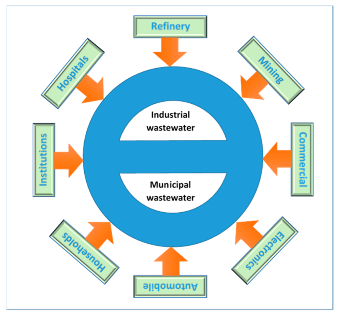
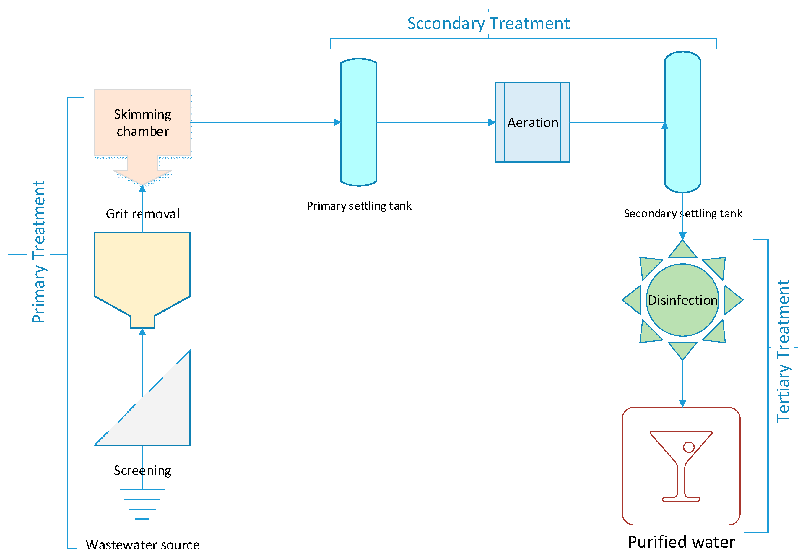
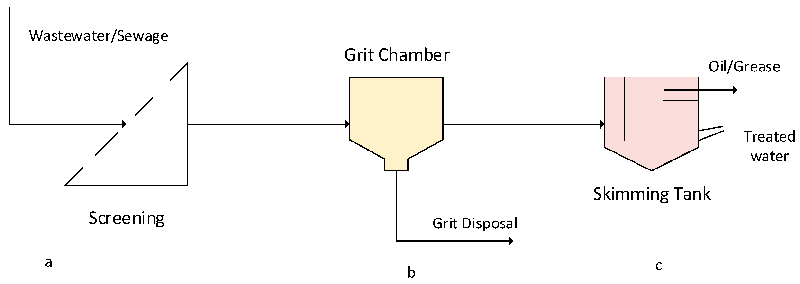
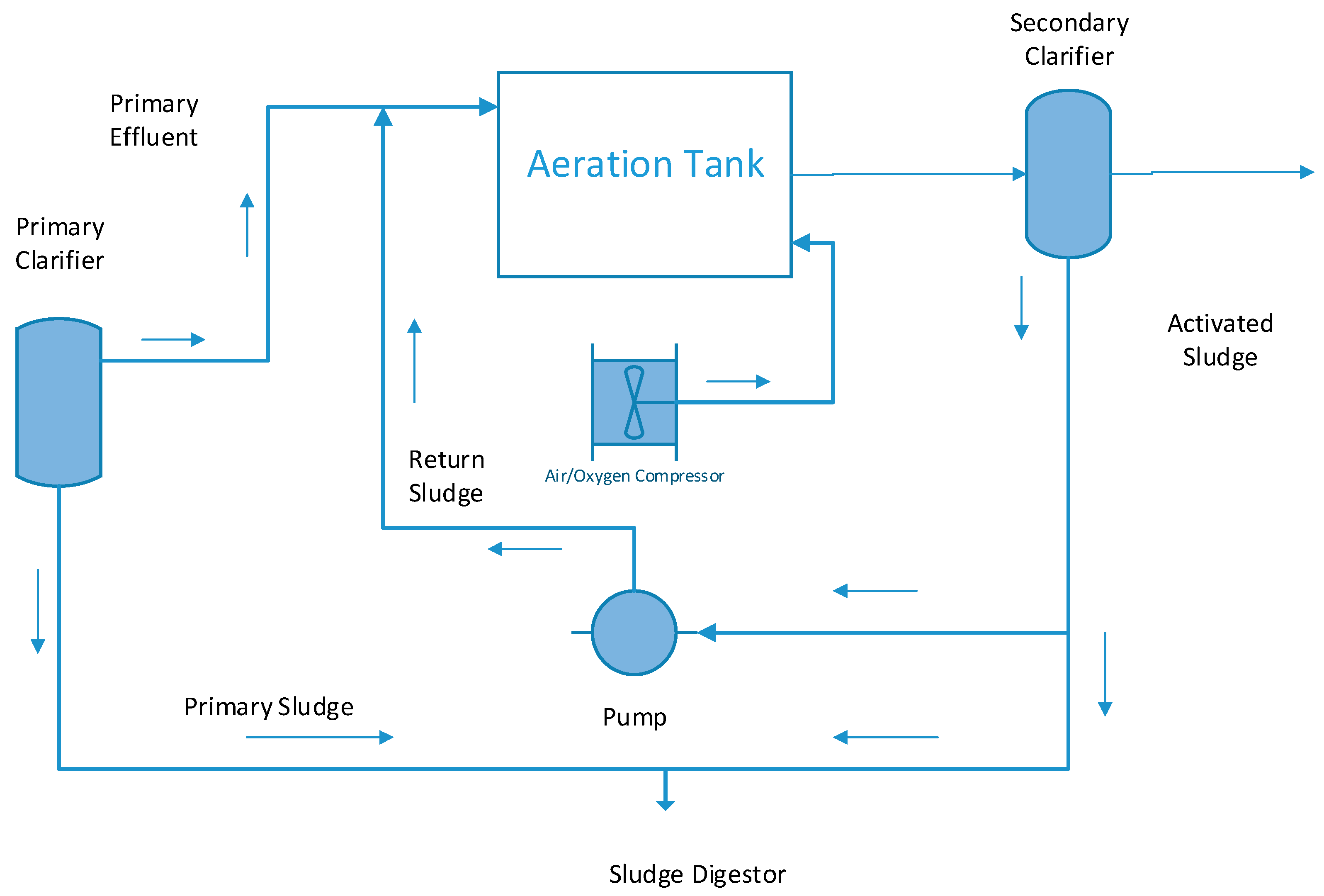
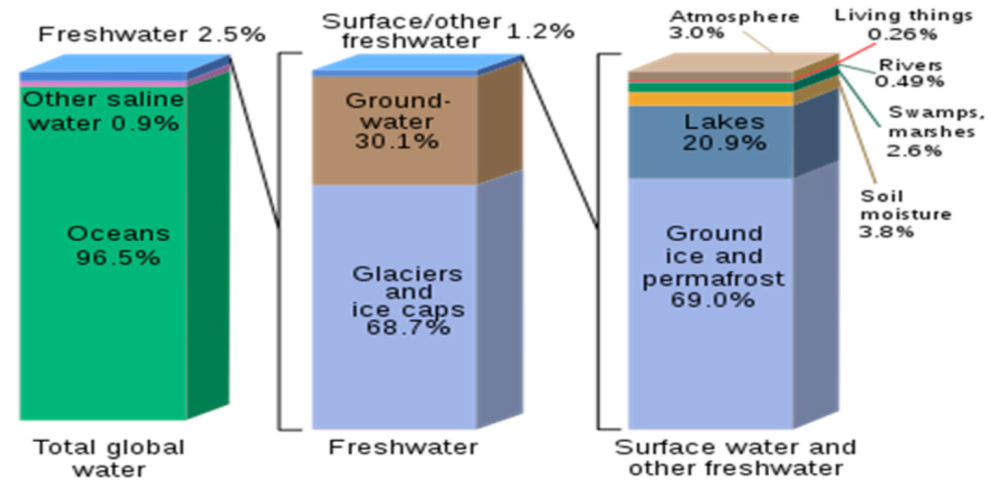
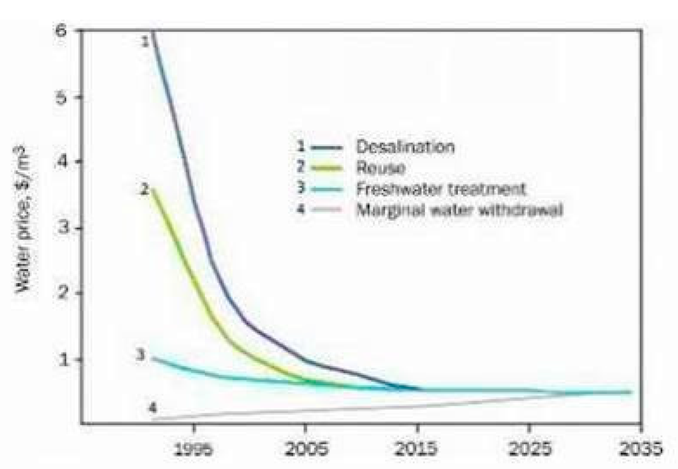
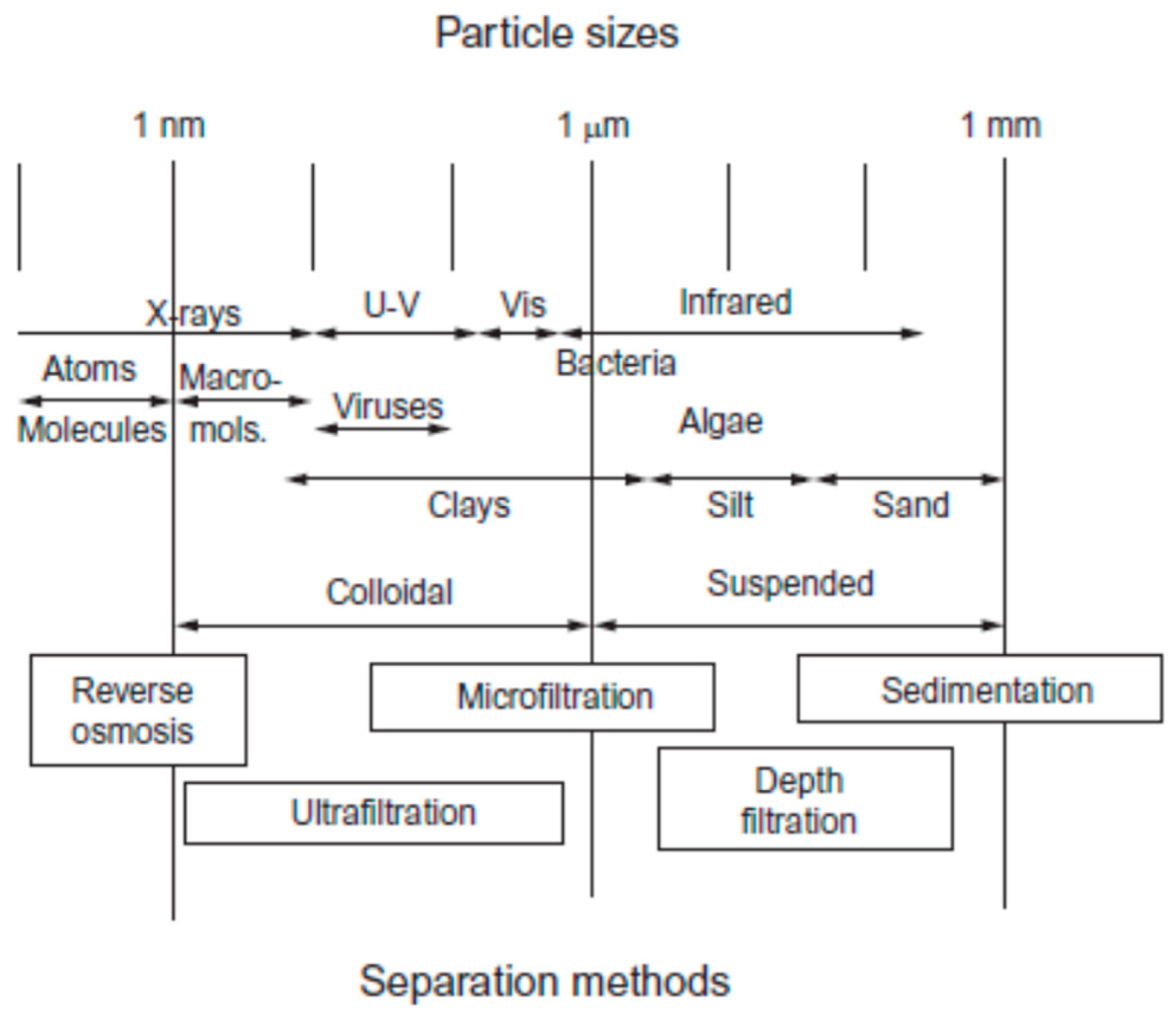
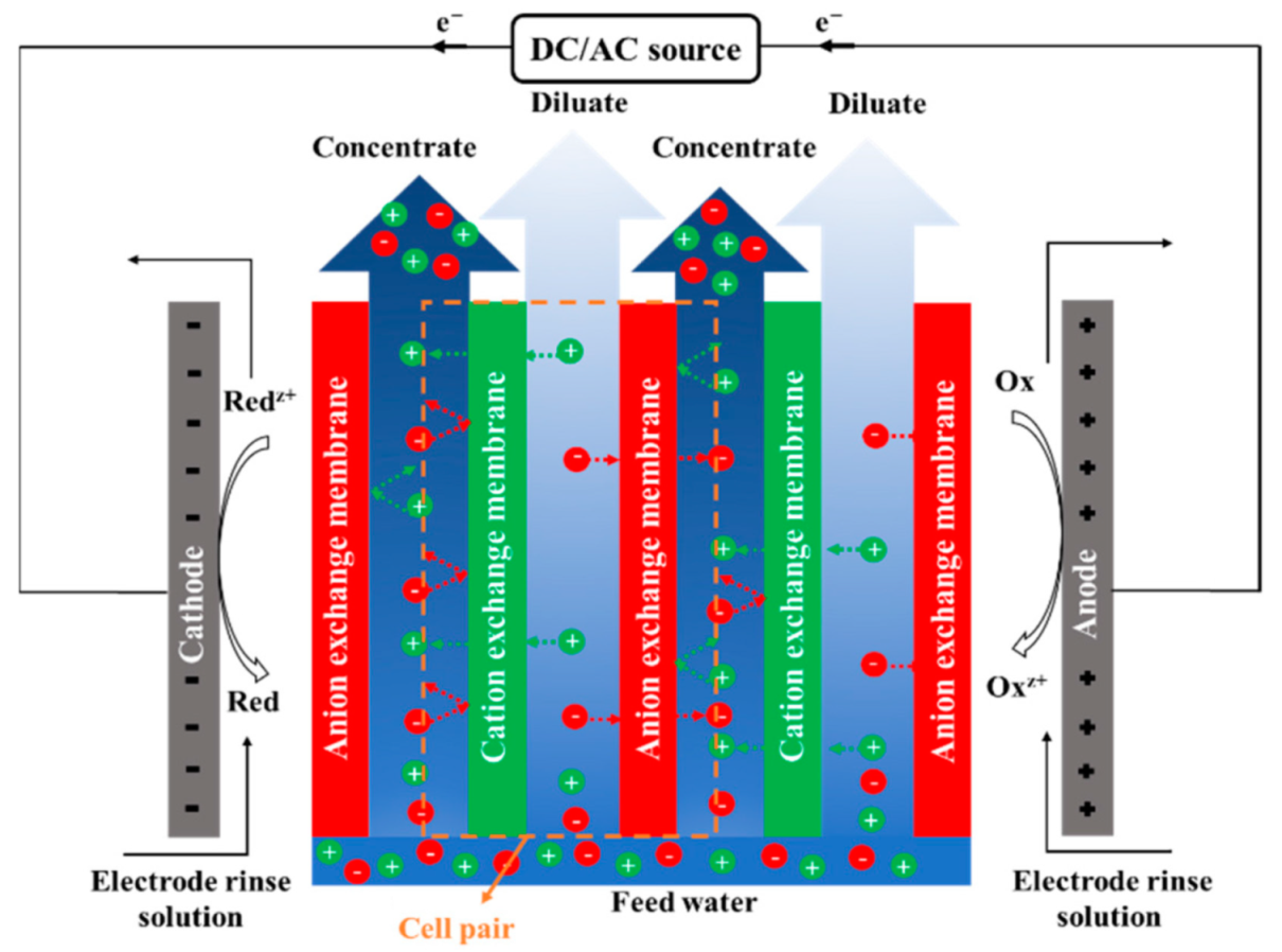
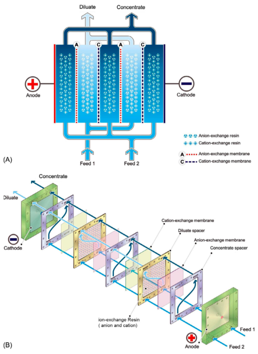
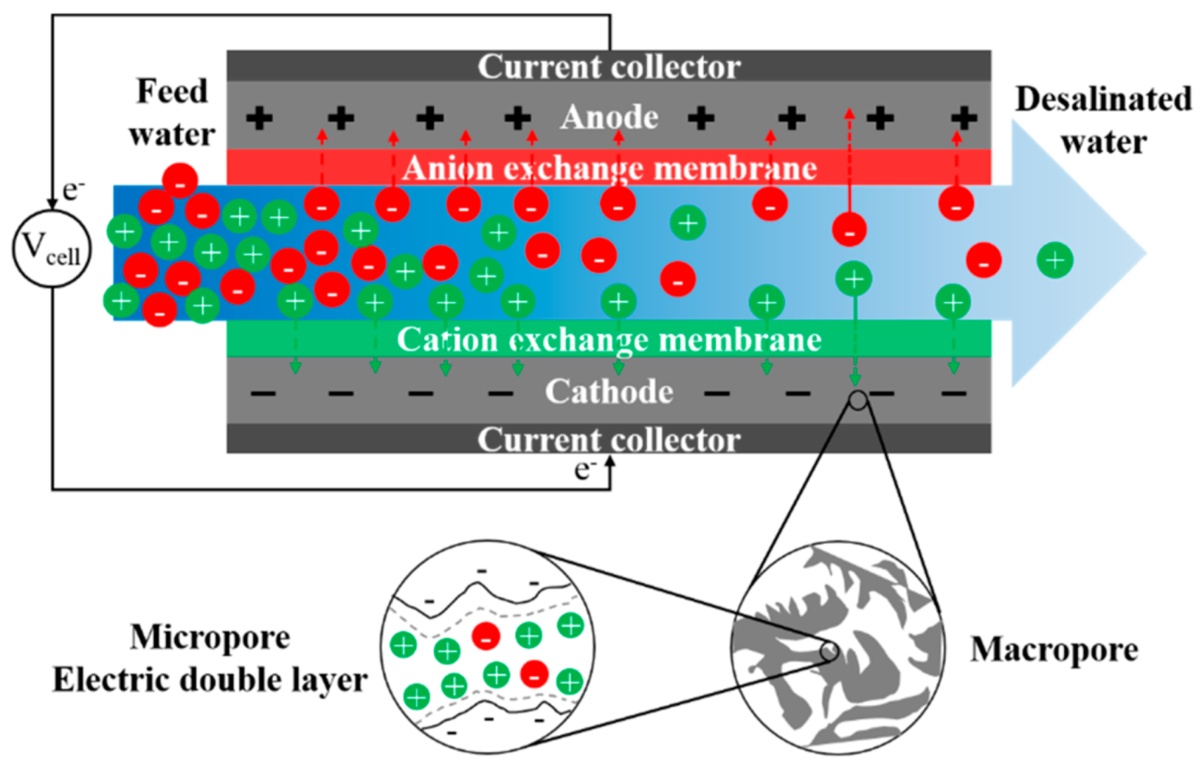
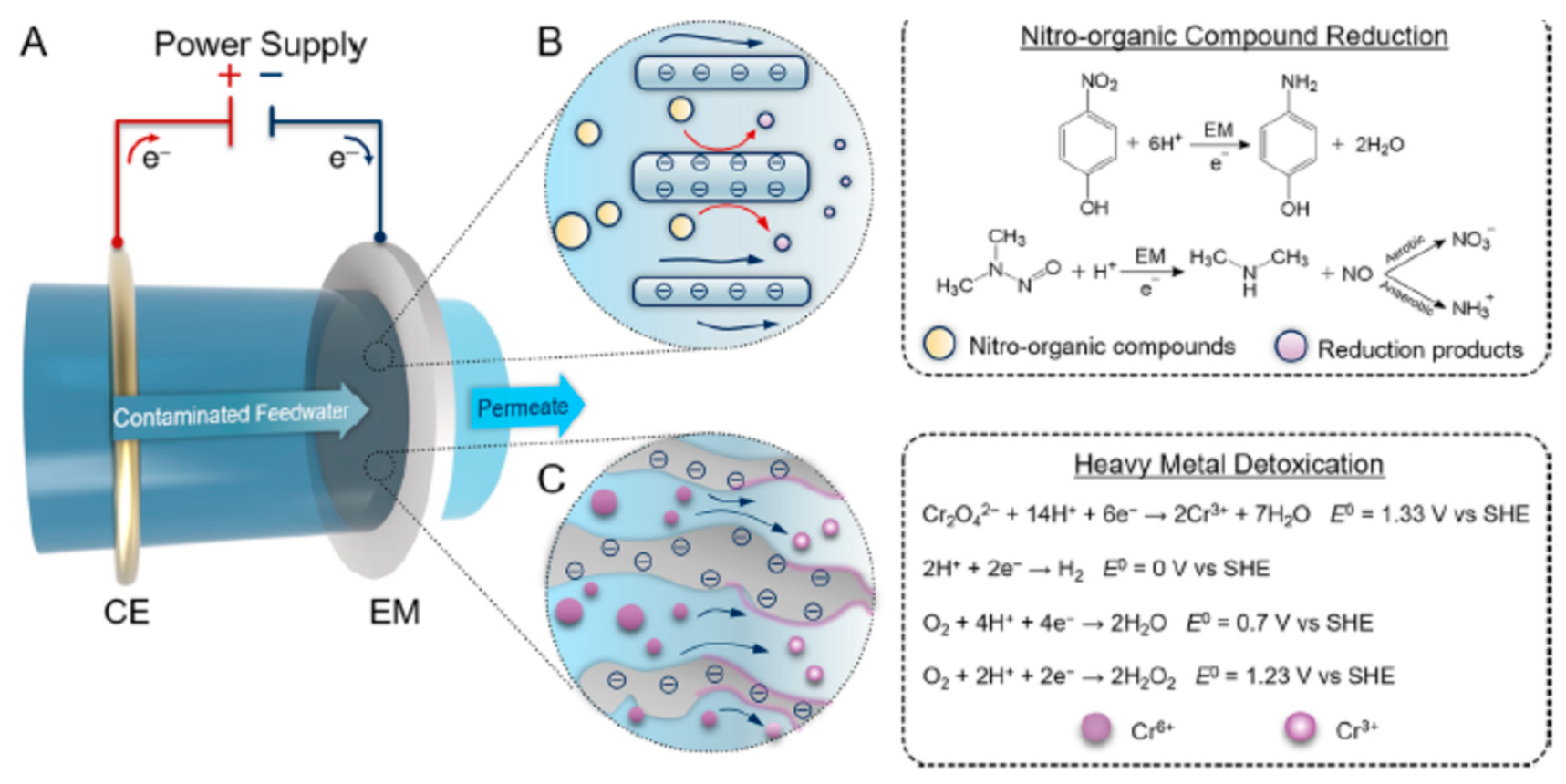
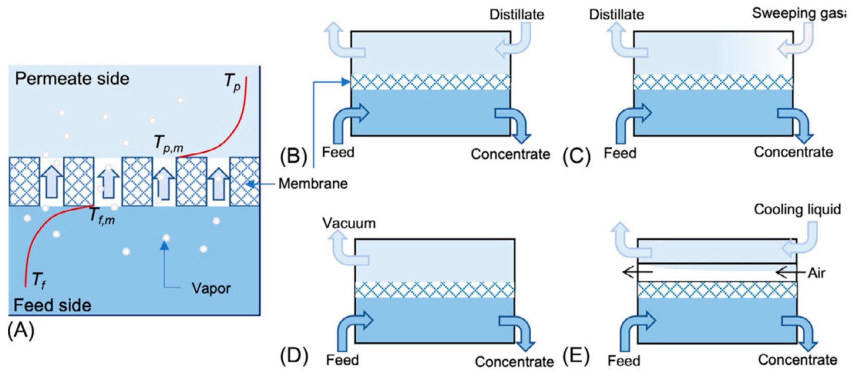
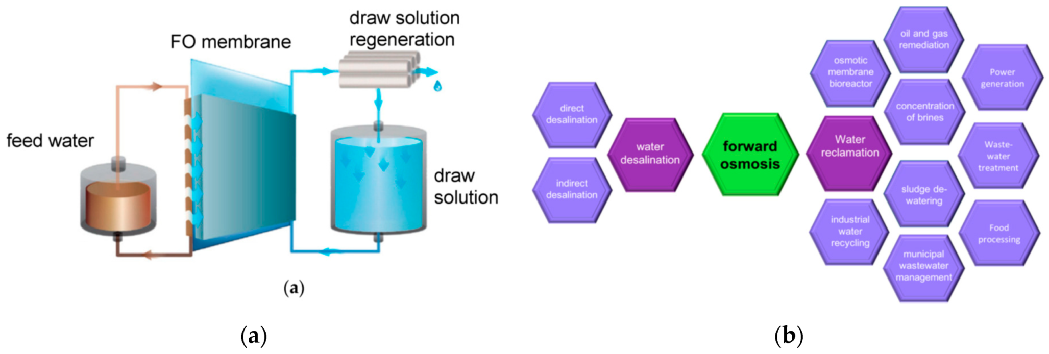
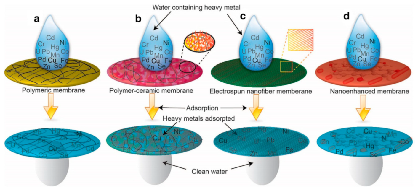
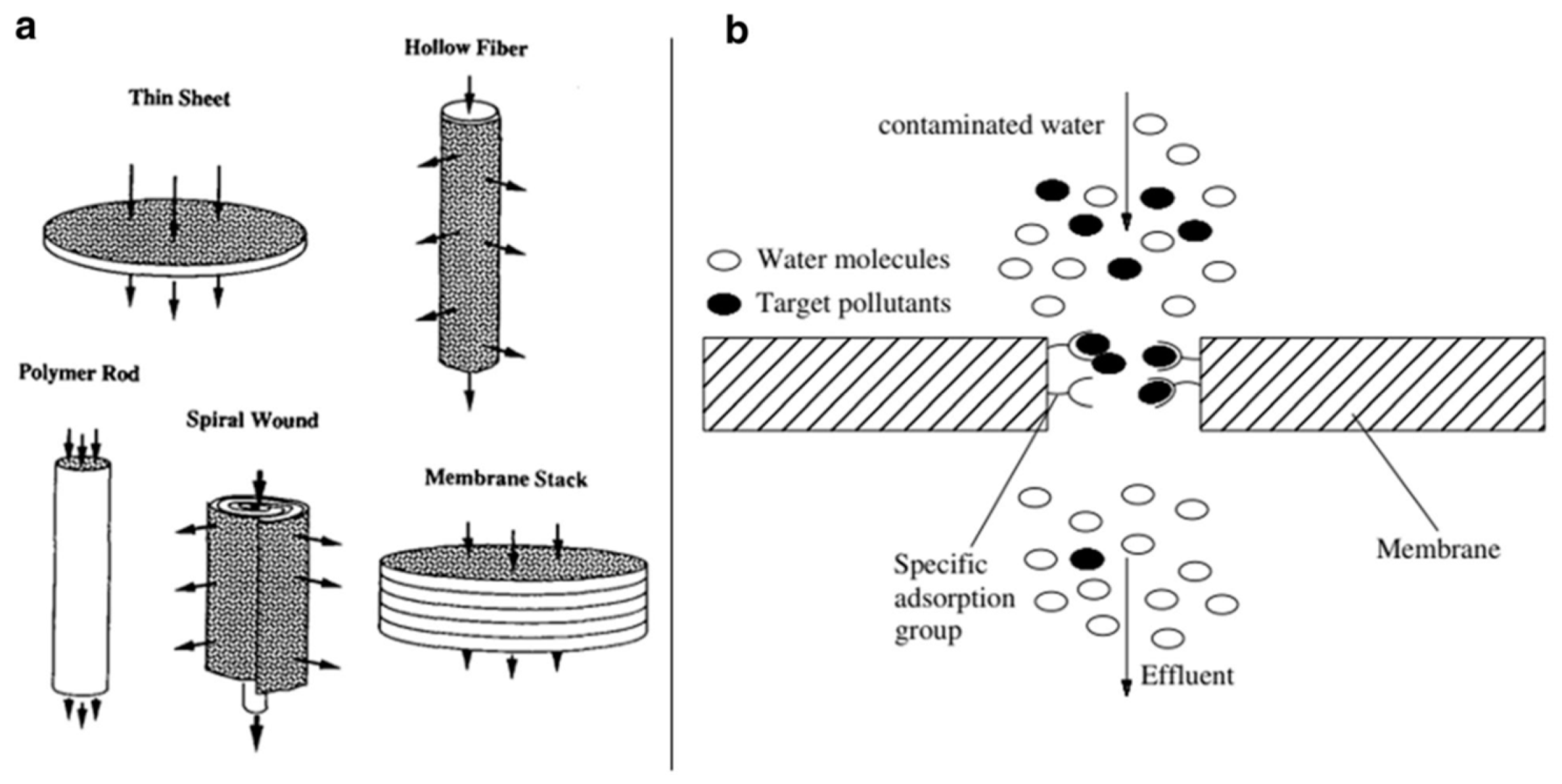
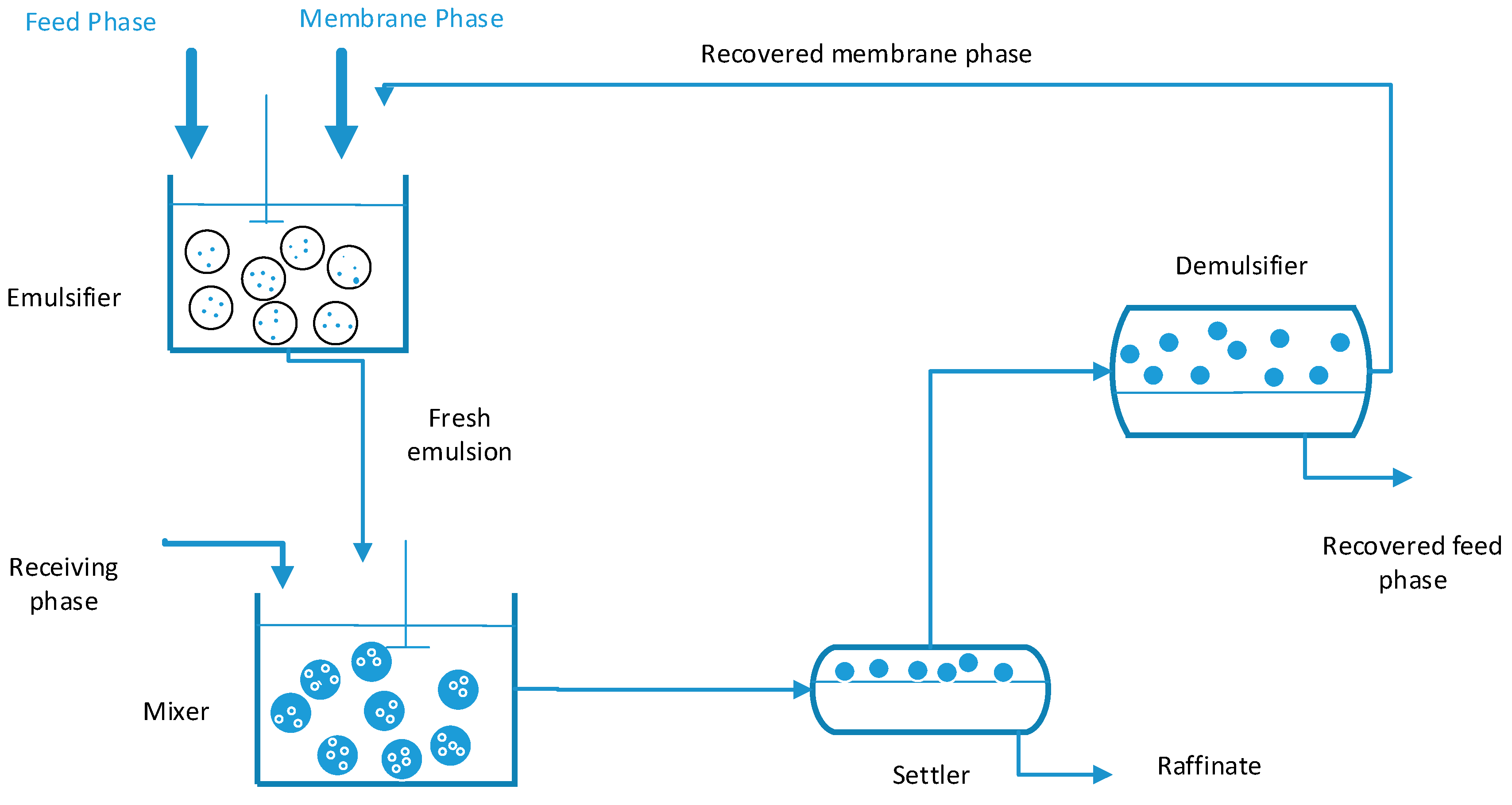
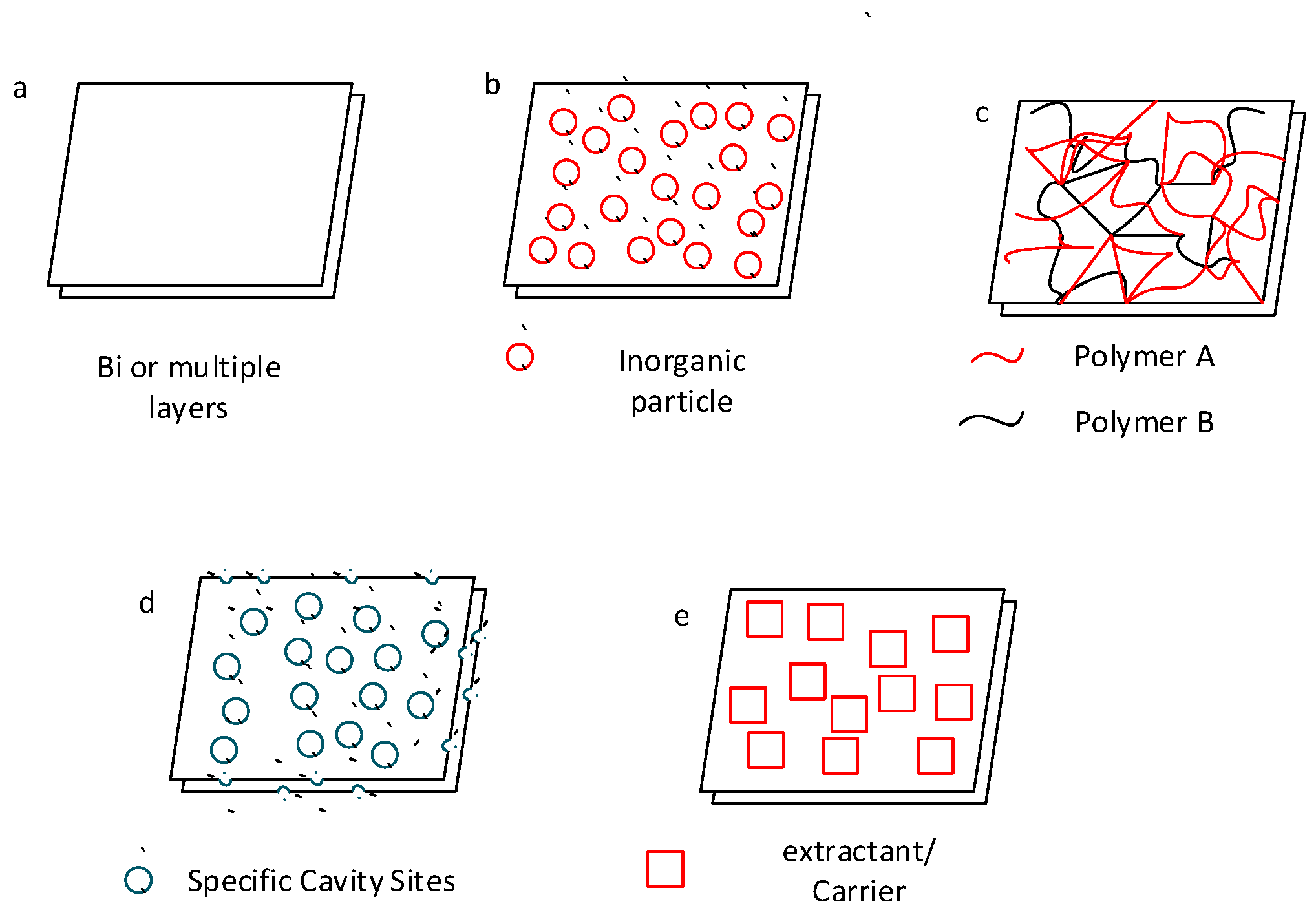
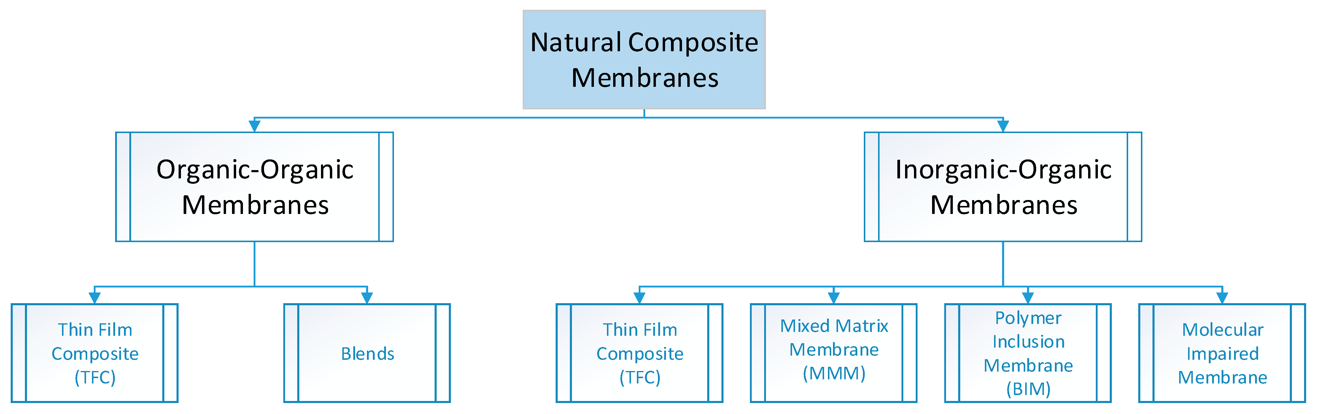
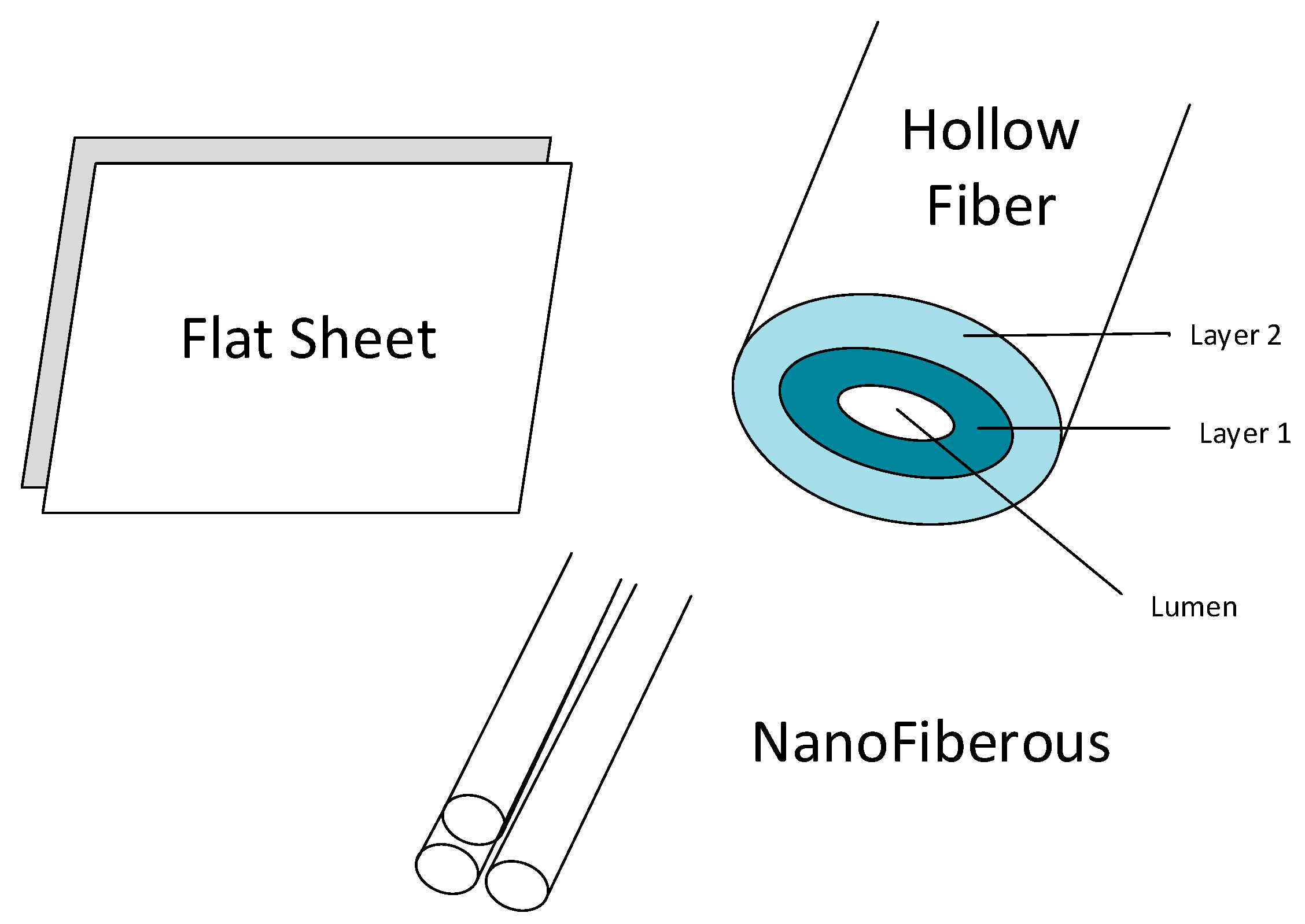
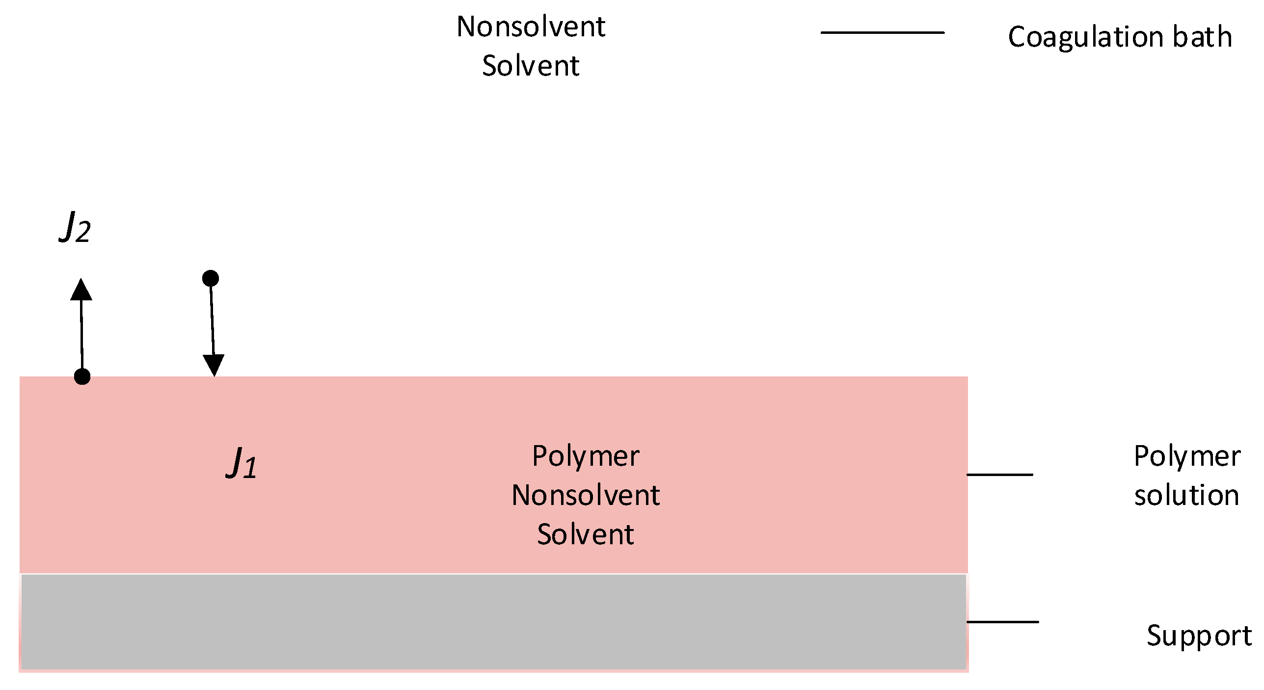
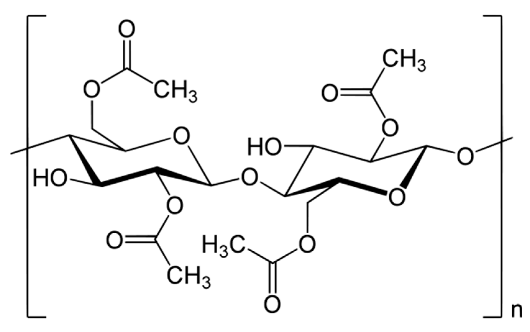
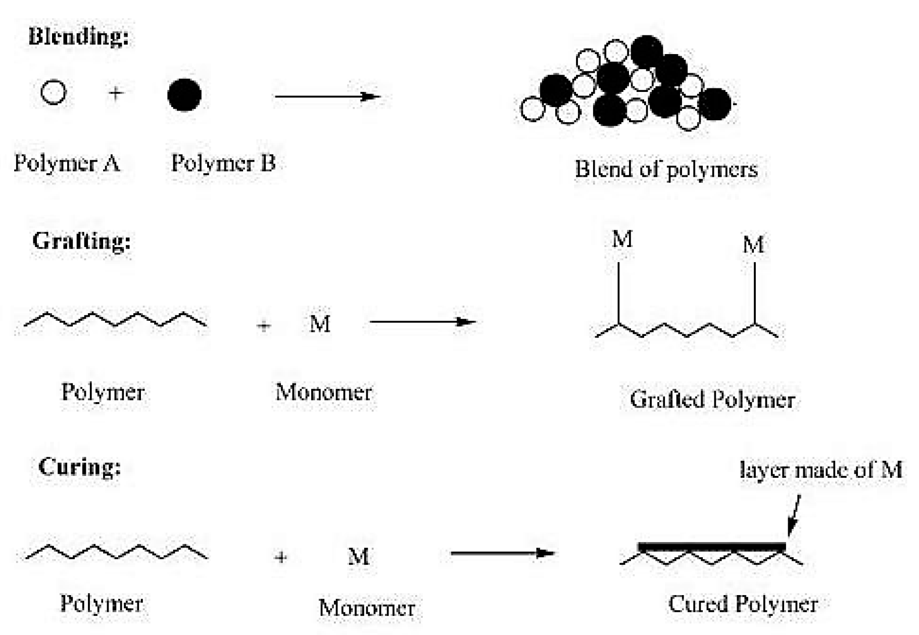
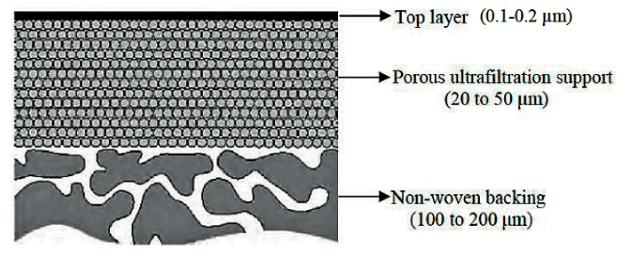
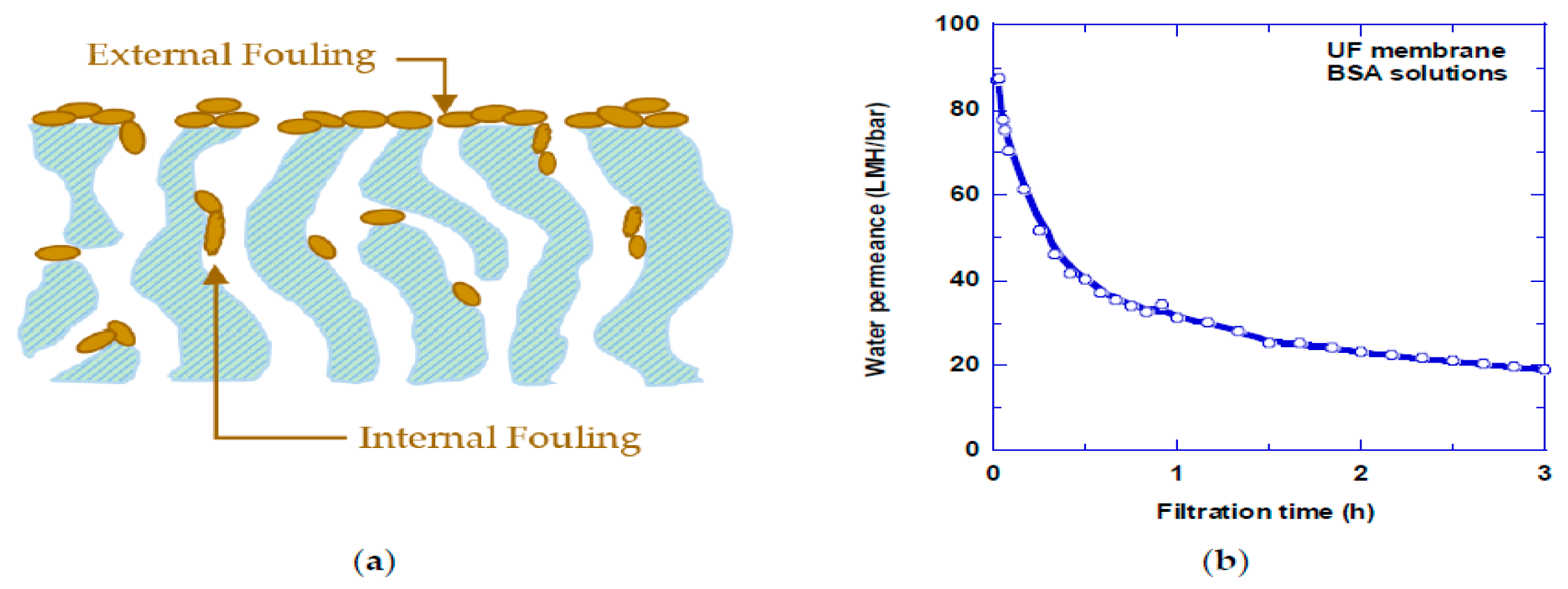
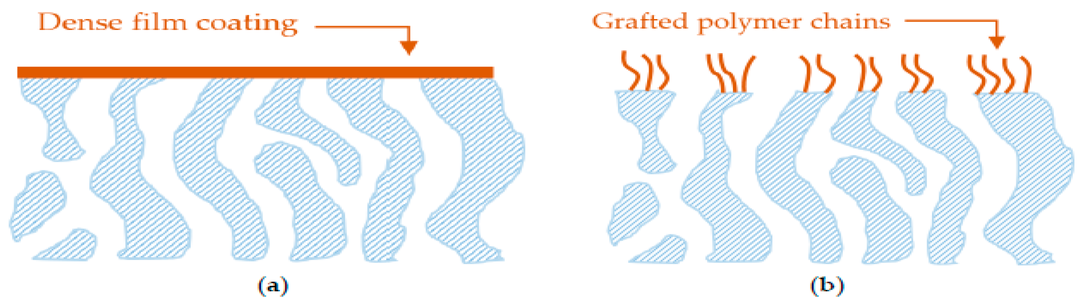
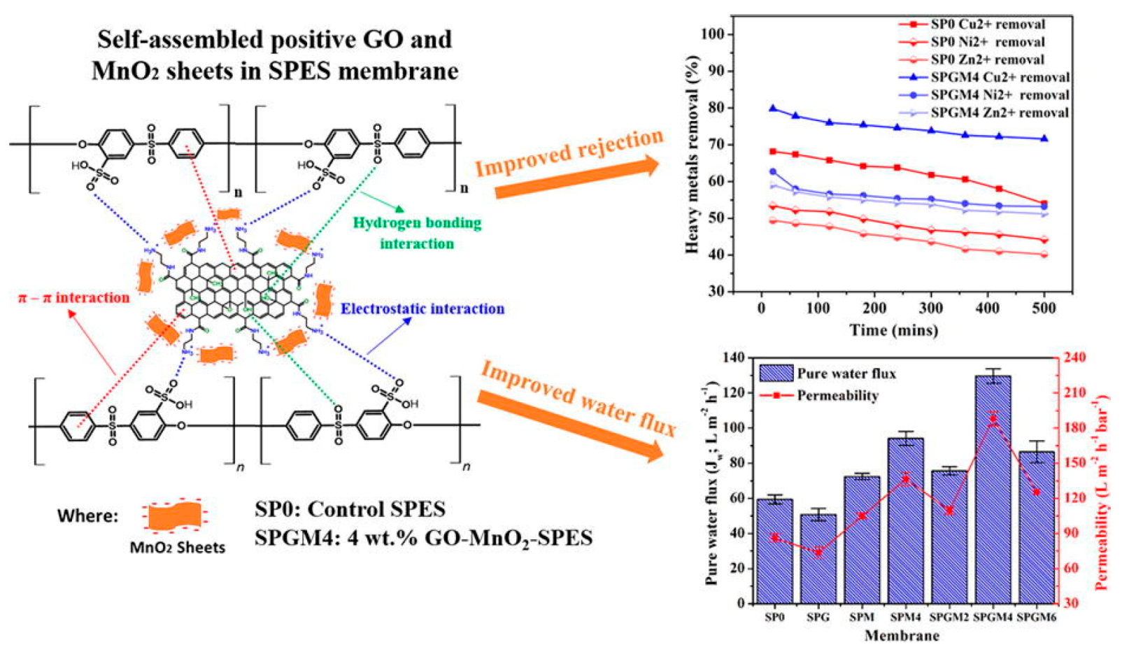
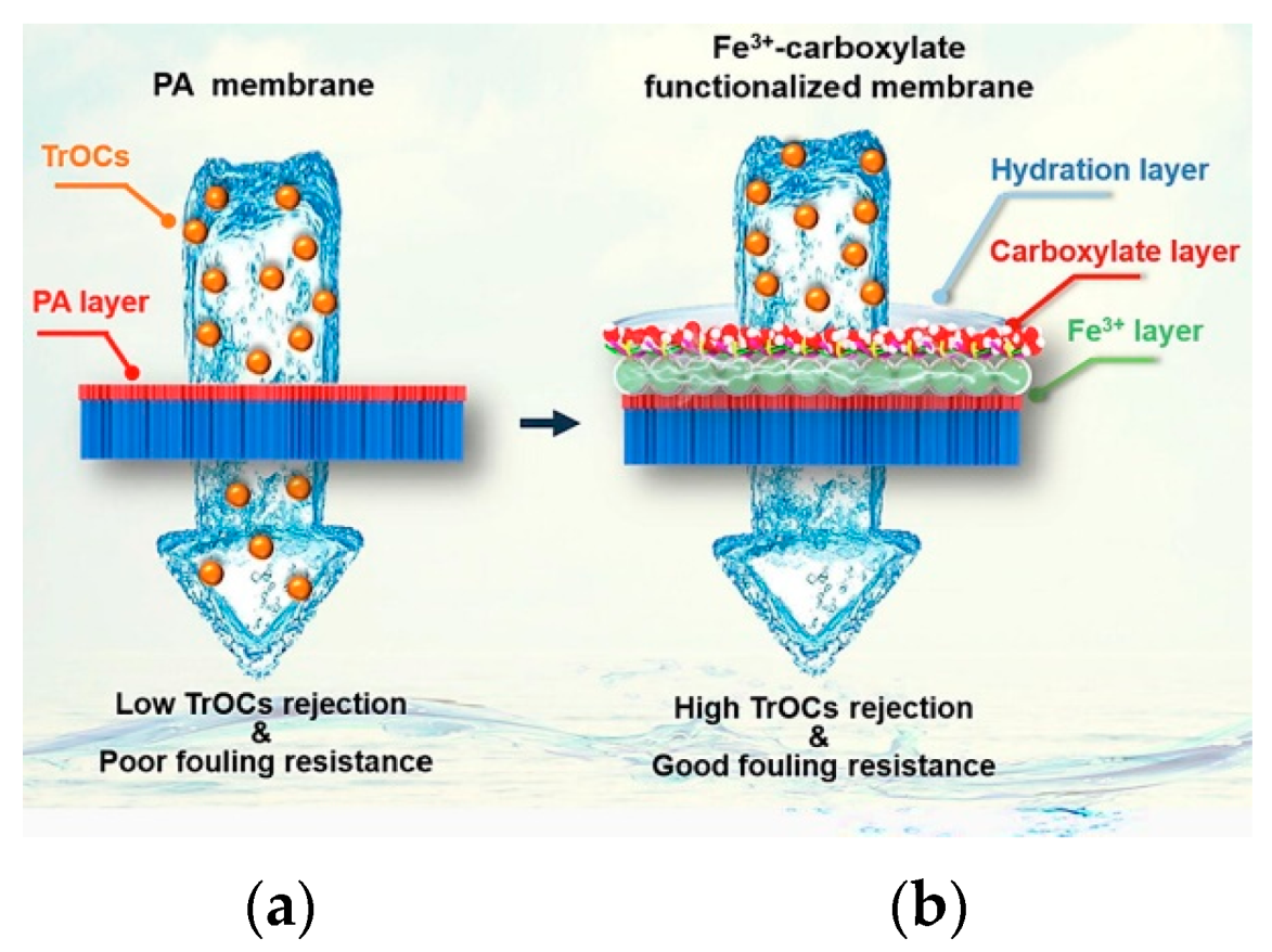
Table 1.
Different wastewater treatment processes’ merits and drawbacks.
| Technology | Merits | Drawbacks |
|---|---|---|
| Coagulation |
|
|
| Trickling filters |
|
|
| RBC |
|
|
| Activated sludge process |
|
|
| Disinfection (Bleaching powder/Cl2 treatment) |
|
|
Table 2.
Performance of MEUF in heavy metal removal.
| Membrane | Surfactant | Metal Ion | Ci (mg/L) | Removal Efficiency (%) | Refs. |
|---|---|---|---|---|---|
| PA | Sodium dodecyl sulfate (SDS) | Co2+ Cr3+ Cs2+ Cu2+ Mn2+ Sr2+ Zn2+ | 50 50 50 50 50 50 50 | 99.8 99.7 83.3 99.2 99.8 99.9 98 | [61] |
| PES | Cetylpyridinium Chloride (CPC) | Cr3+ Ni2+ As5+ | 99 91 98 | [57,62] | |
| Sodium dodecyl sulfate (SDS) | Cd2+ Cu2+ Pb2+ Zn2+ | 50 50 50 50 | 99 99 99 99 | [63] | |
| PS | Zn2+ Cd2+ | 50 50 | 97 98 | [46,64] |
Table 3.
Performance of PEUF in heavy metal removal.
| Membrane | Surfactant | Metal Ion | Ci (Mg/L) | Removal Efficiency (%) | Refs. |
|---|---|---|---|---|---|
| PES | Carboxy methyl cellulose | Cu2+ Cr3+ Ni2+ | 10 10 10 | 97.6 99.5 99.1 | [75] |
| Poly (acrylic acid) | Ni2+ Zn2+ | 93.2 99.9 | [68] | ||
| Polyethyleneimine | Cu2+ Ni2+ Zn2+ | 50 | 94 98.1 91.6 | [68] | |
| Polyvinyl amine | Cu2+ Fe3+ Pb2+ | 10 10 10 | 97 99 99 | [73] | |
| PS | Poly (ammonium acrylate) | Cd2+ | 112.4 | 99 | [74] |
| Polyethyleneimine | Cr3+ | 10 | 99 | [70] | |
| PVA | Polyethyleneimine | Cd2+ Cu2+ Pb2+ | 100 100 100 | 99.5 99.5 99.5 | [67] |
Table 4.
Performance of commercial NF membranes in the removal of heavy metals.
| Membrane | Pressure (MPa) | Metal Ion | Ci (mg/L) | Removal Efficiency (%) | Refs. |
|---|---|---|---|---|---|
| AFC80 | 5.0 | Pb2+ | 100 | 99.9 | [99] |
| AFC80PCI | 4.0 | Cr5+ | 120 | 98.6 | [110] |
| NE 4040–90 | 3.0 | Pb2+ | 400 | 97.5 | [111] |
| AFC30 | 2.0 | Cd2+ Pb2+ Zn2+ | 0.03 0.61 0.50 | 94 97 88 | [103] |
| NF270 | 1.0 | Cr6+ Ni2+ | 60 133 | 95 98.5 | [112] |
| NTR-7250 | 0.3 | Cr3+ Cu2+ Pb2+ | 0.69 0.23 0.03 | 100 99 93 | [113] |
Table 5.
ED performances in heavy metal removal.
| Heavy Metals | Ci (mg/L) | Removal (%) | CE (%) | E (kWh/m3) | Refs. |
|---|---|---|---|---|---|
| Cr6+ | 10 | 99.2 | 3 | [114] | |
| Pb2+ | 1000 | 100 | 72.40 | 0.36 | [115] |
| Zn | 6000 | 80 | 8 | 232.89 | [118] |
CE, current efficiency; Ci, initial concentration; E, energy consumption.
Table 6.
Performances of EDI in heavy metal removal.
| Component To Be Removed | Operating Conditions | Results | Refs. |
|---|---|---|---|
| Uranium | C = 25 Q = 5–10 V = 2.5–5.0 I = 0.05–0.10 | Removal >98% | [144] |
| Zn, Cu, Cd | CZn = 40 CCu = 6 CCd = 4 I = 400 | Product conductivity = 40 μS/cm Concentrating factor > 100. | [145] |
| Cr6+ | Q = 200 C = 50 I = 50 | Removal = 100% | [146] |
| Sr2+ | C = 50 | CSr in product = 0.0415 EC = 7.66 kWh/m3 | [147] |
Am, membrane area (cm2); C, ion concentration (mg/L); CE, current efficiency; EC, energy consumption; i, current density (A/m2); I, current (A); Q, flow rate (mL/min); V, applied voltage (volt).
Table 7.
Heavy metal removal by EC method [169]. Reproduced with permission from Fu, F.; Wang, Q., Removal of Heavy Metal Ions from Wastewaters: A Review, published by Academic Press, 2011.
Table 7.
Heavy metal removal by EC method [169]. Reproduced with permission from Fu, F.; Wang, Q., Removal of Heavy Metal Ions from Wastewaters: A Review, published by Academic Press, 2011.
| Heavy Metal | Current Density | Initial Conc. (mg/L) | Optimum pH | Removal Efficiency (%) | Ref |
|---|---|---|---|---|---|
| Mn2+ | 6.25 mA/cm2 | 100 | 7.0 | 78.2 | [170] |
| Ni2+, Zn2+ | 9 mA/cm2 | 248, 270, 282; 217, 232, 236 | 6.0 | 100 | [166] |
| As3+, As5+ | 3.7–4.6 mA/cm2 | 2.24 | 8.5 | >99 | [171] |
| Cr6+ | Current 7.4 A | 1470 | 1.84 | 100 | [168] |
Table 8.
MD performances for heavy metal removal.
| Heavy Metals | Configuration | Operating Conditions | Results | Refs. |
|---|---|---|---|---|
| Pb, Cd, Cr, Cu, and Ni | AGMD | C = 2500 | J > 23 | [177] |
| As | DCMD | T = 30–61 C = 1.2 | R = 100 J = 49.8 | [180] |
| Zn, Ni, Cu | VMD | T = 57 CZn = 600–3000 CNi = 200–1000 CCu = 400–2000 | Permeate conductivity < 40 μS/cm J = 6 | [176] |
| Membrane | Feed Solution | Draw Solution | Rejection | Flux | Ref |
|---|---|---|---|---|---|
| (PES) hollow fibers | Cd2+ Pb2+ | Biogas slurry | Cd2+ = 98.5% Pb2+ = 97% | 6.8 LMH | [193] |
| Bovine serum albumin (BSA)- embedded PA TFC | Cd2+ Cu2+ Pb2+ | NaCl | >99% | 45–50 LMH | [194] |
| HTI TFC | Hg2+ | MgCl2 | 99/9% | [195] | |
| Cellulose acetate | Cd2+ | Hydrated MgSO4 | 78.8% | 50 LMH | [196] |
| TFC | Pb2+ | NaCl | 99% | 80 LMH | [197] |
| TFC FO | Hg2 | NaCl | 95% | 5 LMH | [198] |
Table 10.
Advantages and disadvantages of different AMs fabrication methods [199].
Table 10.
Advantages and disadvantages of different AMs fabrication methods [199].
| AMs | Advantages | Disadvantages |
|---|---|---|
| PMs | Polymer material is available in a wide range of options. Membranes having a smooth/porous surface membrane are easy to combine polymer components with. Recuperation and re-use applications | Thermal stability is a limitation |
| PCMs | Method of manufacturing that is simple and rough Non-toxicity, cheap cost, high cation exchangeability, and mechanical and chemical stability are all advantages of the lamellar structure. | Methods of recuperation that are foul, slower, and more intense Due to hand compression and distortion during the ceramics firing process, there are many depressions and tiny fractures on the membrane surface. Due to the stack of lamellar structures, certain locations are inaccessible and have low surface areas. Limit the number of recyclables. |
| ENMs | There are several options for the material. Nanofibers are simple to integrate compounds into. Controlling nanofiber diameter, microstructure, and arrangement with great flexibility Membranes having a high surface-to-volume ratio and a high porosity (>90.0%) Nanostructures in abundance: nanofibers with bilayers and tri-layers Applying for re-use and regeneration | Nanofibers with diameters less than 100 nm are difficult to obtain. ENMs with maximal pore diameters less than 100 nm are difficult to obtain. Slow pace of yield |
| NEMs | Surface contact is greater, reactivity is higher, and disposal ability is better. The most accurate description of the membrane’s nanomaterials’ function Mechanical strength, carbon matrix compatibility with polymeric structure, and strong contacts and adhesion Recuperation and re-use applications | Particles with a limited size distribution are required. Reduced energy demand Membrane cleaning, membrane durability, and membrane performance all necessitate the use of chemicals. |
Table 11.
Performance of heavy metal removal using AMs [199].
Table 11.
Performance of heavy metal removal using AMs [199].
| AMs | Adsorbents | Heavy Metal Ions | Removal Efficiency (%) | pH | Recycling Method | Refs |
|---|---|---|---|---|---|---|
| PMs | CTS/PEG | Fe2+, Mn2+ | 5.0, 5.9 | 0.1 M HCl | [200] | |
| GLA-cCTS | Hg2+ | 35.2 | 6.0 | 1 M NaCl, | [201] | |
| ECH-cCTS | Cr6+ | 5.5, 92.0 | 2.0, 6.0 | 1 M NaCl, | [202] | |
| CTS | Cu2+ | 97.2 | 5.0 | 1 M NaCl | [203] | |
| PVA/PE | Pb2+, Cd2+, Cu2+ | 60.0, 26.0, 16.0 | 5.0 | 1 M NaCl | [67] | |
| CTS/PVA/PEI | Cd2+, Cu2+, Ni2+ | 4.8, 57.4, 50.3 | 6.0 | 0.03 M H2SO4 | [204] | |
| PCMs | PANOB | Cu2+, Zn2+, Cd2+ | 9.8, 98.9, 97.4 | 2.0–7.0 | 0.1 M HCl | [205] |
| CMC | Se4+ | 19 | 4.0–4.5 | NaCl | [206] | |
| Fe oxide-PE8M | Cr6+ | 95.0 | 0.0–9.0 | HCl, NaOH | [207] | |
| CPBC | Cu2+, Zn2+ | 95.0, 85.0 | 0.0, 7.0 | 0.05 M Ca (NO3)2 | [208] | |
| ENMs | AOPAN/RC | Fe3+, Cu2+, Cd2+ | 31.2, 11.5, 2.9 | 0.0, 5.0, 6.0 | 0.1 M HCl | [209] |
| PEI/PES | Pb2+, Cu2+, Cd2+ | 90.4, 89.8, 93.2 | 5.0–7.0 | 0.05 M HCl, 0.05 M HNO3 | [210] | |
| CTS | Ni2+, Cu2+ | 46.0, 68.7 | 5.0 | 0.1 M NaOH, 1 M HNO3 | [211] | |
| PAN/CTS | Cd2+, Pb2+ | 51.1, 52.9 | 7.0, 5.0 | EDTA | [212] | |
| NEMs | CCGO | Cr6+ | 81.2 | 3.0 | 0.1 M NaOH | [213] |
| GO/PSf | Cu2+, Cd2+, Pb2+ | >90.0 | 6.5, 6.4, 6.7, 3.5 | DI H2O/HCl | [214] | |
| PAN/MO | Hg2+ | 86 | 5.0 | 1 M HNO3 | [215] | |
| pHEMA/CTS | Cd2+, Pb2+ | 36.4, 77.2 | DI H2O | [216] |
Table 12.
Materials for PIMs [237]. Reproduced with permission from Keskin, B.; Zeytuncu-Gökoğlu, B.; Koyuncu, I, Chemosphere; published by Elsevier, 2021.
Table 12.
Materials for PIMs [237]. Reproduced with permission from Keskin, B.; Zeytuncu-Gökoğlu, B.; Koyuncu, I, Chemosphere; published by Elsevier, 2021.
| Base Polymer | Carrier | Plasticizers | Evaporation Time | Ref |
|---|---|---|---|---|
| PVC | D2EHPA | – | 24 h | [238] |
| CTA | Kelex 100 | THEP | 24 h | [239] |
| CTA | Cyphos 104 | NPOE | Overnight | [240] |
| CTA | D2EHPA | – | 24 h | [241] |
| PVC | LIX 84 | NPOE | Overnight | [242,243] |
| CTA | ONPPE | ONPPE | Overnight | [244] |
| CTA | Cyphos IL 101 | ONPPE | 12 h | [245] |
| CTA | TIOA | ONPPE | 12 h | [246] |
| PVC | Cyanex 301 | ONPPE | 12 h | [247] |
| CTA | D2EHPA | DOP | Overnight | [248] |
Table 13.
BIM performance and results [237]. Reproduced with permission from Keskin, B.; Zeytuncu-Gökoğlu, B.; Koyuncu, I, Chemosphere; published by Elsevier, 2021.
Table 13.
BIM performance and results [237]. Reproduced with permission from Keskin, B.; Zeytuncu-Gökoğlu, B.; Koyuncu, I, Chemosphere; published by Elsevier, 2021.
| Materials | Transportation | Results | Ref |
|---|---|---|---|
| PVC-TIOA-ONPPE | Copper, cobalt, and nickel | 91% of recovery rate for containing TIOA carriers | [249] |
| CTA-TEHP-Kelex 100 | Nickel | Using KELEX 100 as carrier was efficiently achieved to transport nickel. | [239] |
| CTA-D2EHPA | Zinc, cobalt, and nickel | Metal transport and recovery increased with the increasing carrier. | [241] |
| PVC-LIX84-NPOE | Cobalt | As the carrier concentration increases, first the transport increases and then begins to decrease. | [242,243] |
| CTA-ONPPE | Copper | The recovery rate was 80%. | [244] |
| CTA- Cyphos IL 101-ONPPE | Copper, cobalt, and nickel | Metal transport and recovery increased with increasing carrier and HCl concentration. | [245] |
| CTA-ONPPE-NPOE | Zinc | The CTA-based membrane was better than PVC- based membranes. | [250] |
| PVC-TIOA-ONPPE | Copper, cobalt, and nickel | 91% of recovery rate for containing TIOA carriers | [249] |
Table 14.
Examples of fabrication methods and polymers used for the preparation of polymeric membranes widely used in water and wastewater treatments [266]. Reproduced with permission from Lalia, B.S.; Kochkodan, V.; Hashaikeh, R.; Hilal, N, Desalination; published by Elsevier, 2013.
Table 14.
Examples of fabrication methods and polymers used for the preparation of polymeric membranes widely used in water and wastewater treatments [266]. Reproduced with permission from Lalia, B.S.; Kochkodan, V.; Hashaikeh, R.; Hilal, N, Desalination; published by Elsevier, 2013.
| Membrane Technology | Fabrication Methods | Polymers Used in Fabrication Process |
|---|---|---|
| MF | Phase inversion Stretching Track-etching | PVDF PTFE Polypropylene (PP) Polyethylene (PE) PES Polyetheretherketone (PEEK) |
| UF | Phase inversion Solution wet spinning | Polyacrylonitrile (PAN) PS PES Poly (phthazine ether sulfone ketone) (PPESK) Poly (vinyl butyral) PVDF |
| NF | Interfacial polymerization Layer-by-layer deposition Phase inversion | PA PS Polyols Polyphenols |
| RO | Phase inversion Solution casting | CA/triacetate Aromatic PA Polypiperzine Polybenziimidazoline |
| MD | Phase inversion Stretching Electrospinning | PTFE PVDF |
Table 15.
Main polymers used for film formation and the advantages and disadvantages [270]. Reproduced with permission from Smitha, B.; Sridhar, S.; Khan, A.A, Journal of Membrane Science; published by Elsevier B.V., 2005.
Table 15.
Main polymers used for film formation and the advantages and disadvantages [270]. Reproduced with permission from Smitha, B.; Sridhar, S.; Khan, A.A, Journal of Membrane Science; published by Elsevier B.V., 2005.
| Polymer | Advantages | Disadvantages |
|---|---|---|
| CA | Hydrophilicity Flexibility in fabrication Low cost | Low thermal resistance (<30 °C) Low chemical resistance pH range (2–8) Poor resistance to chlorine (Cl2) |
| PS and PES | High thermal resistance Hydrophobicity Wide pH tolerances (1–13) Good Cl2 resistance Flexibility in membrane fabrication (wide range of pore size) High mechanical characteristics | Low operating (up to 75 °C pressure limits |
| PVDF | High mechanical strength Hydrophobicity and chemical resistance | Thermally stable (up to 75 °C) |
| Polyamide (PA) | Wide pH tolerance High thermal stability and high mechanical properties | Poor Cl2 resistance |
Publisher’s Note: MDPI stays neutral with regard to jurisdictional claims in published maps and institutional affiliations. |
© 2021 by the authors. Licensee MDPI, Basel, Switzerland. This article is an open access article distributed under the terms and conditions of the Creative Commons Attribution (CC BY) license (https://creativecommons.org/licenses/by/4.0/).
Share and Cite
MDPI and ACS Style
El Batouti, M.; Al-Harby, N.F.; Elewa, M.M. A Review on Promising Membrane Technology Approaches for Heavy Metal Removal from Water and Wastewater to Solve Water Crisis. Water 2021, 13, 3241. https://doi.org/10.3390/w13223241
AMA Style
El Batouti M, Al-Harby NF, Elewa MM. A Review on Promising Membrane Technology Approaches for Heavy Metal Removal from Water and Wastewater to Solve Water Crisis. Water. 2021; 13(22):3241. https://doi.org/10.3390/w13223241
Chicago/Turabian StyleEl Batouti, Mervette, Nouf F. Al-Harby, and Mahmoud M. Elewa. 2021. "A Review on Promising Membrane Technology Approaches for Heavy Metal Removal from Water and Wastewater to Solve Water Crisis" Water 13, no. 22: 3241. https://doi.org/10.3390/w13223241
Note that from the first issue of 2016, this journal uses article numbers instead of page numbers. See further details here.