
Electrochemical/Peroxymonosulfate/NrGO-MnFe2O4 for Advanced Treatment of Landfill Leachate Nanofiltration Concentrate

1
School of Water Conservancy and Environment, Zhengzhou University, Zhengzhou 450001, China
2
School of Ecology and Environment, Zhengzhou University, Zhengzhou 450001, China
*
Author to whom correspondence should be addressed.
Water 2021, 13(4), 413; https://doi.org/10.3390/w13040413
Submission received: 15 December 2020
/
Revised: 31 January 2021
/
Accepted: 1 February 2021
/
Published: 4 February 2021
(This article belongs to the Section Wastewater Treatment and Reuse)
Abstract
:A simple one-pot method was used to successfully embed manganese ferrite (MnFe2O4) nanoparticles on the nitrogen-doped reduced graphene oxide matrix (NrGO), which was used to activate peroxymonosulfate to treat the landfill leachate nanofiltration concentration (LLNC) with electrochemical enhancement. NrGO-MnFe2O4 and rGO-MnFe2O4 were characterized by various means. This indicates that nitrogen-doped could induce more graphene oxide (GO) spall and reduction to produce more active centers, and was favorable for uniformly loading MnFe2O4 particles. The comparison between electrochemical/peroxymonosulfate/NrGO-MnFe2O4 (EC/PMS/NrGO-MnFe2O4) system and different catalytic systems shows that electrochemical reaction, NrGO and MnFe2O4 can produce synergies, and the chemical oxygen demand (COD) removal rate of LLNC can reach 72.89% under the optimal conditions. The three-dimensional (3D-EEM) fluorescence spectrum shows that the system has a strong treatment effect on the macromolecules with intense fluorescence emission in LLNC, such as humic acid, and degrades into substances with weak or no fluorescence characteristics. Gas chromatography-mass spectrometry (GC-MS) indicates that the complex structure of refractory organic compounds can be simplified, while the simple small molecular organic compounds can be directly mineralized. The mechanism of catalytic degradation of the system was preliminarily discussed by the free radical quenching experiment. Therefore, the EC/PMS/NrGO-MnFe2O4 system has significant application potential in the treatment of refractory wastewater.
1. Introduction
At present, due to its advantages of low cost and easy operation, sanitary landfill is always the first choice for solid waste treatment in most developing countries [1]. However, this treatment can lead to leachate. Studies have demonstrated that this kind of high-strength wastewater containing high concentrations of organic matter, inorganic salts, and heavy metals is one of the important pollutant sources of groundwater and surface water [2]. However, traditional biological treatment cannot effectively remove organic matter from the leachate [3]. During membrane treatment, pollutants in leachate are enriched, accounting for approximately 13–14% of the pre-treatment volume [4]. Compared with leachate, it has higher refractory organic concentration, higher salinity, and lower biodegradability, making it more difficult to process [5].
The main treatment methods of landfill leachate nanofiltration concentration (LLNC) are the recharge method, the membrane distillation method, the evaporation method, and advanced oxidation processes (AOPs). Recycling leads to the accumulation of contaminants, and membrane distillation is costly. In the process of evaporation, not only are the pollutants not thoroughly treated, but also the equipment is corroded. AOPs can effectively degrade a large number of refractory organic compounds, reduce colour number (CN) and improve biodegradability, which has become one of the key development directions of LLNC treatment. Among the AOPs used to treat LLNC, most belong to Fenton technology, which is based on reactive hydrogen peroxide (H2O2) to generate hydroxyl radical (•OH) [6,7,8]. However, compared with hydrogen peroxide (H2O2, E0 = +1.77 v), peroxymonosulfate (PMS, E0 = +1.82 v), and peroxosulphate (PS, E0 = +2.01 v) with peroxide bonds (O-O) have higher standard redox potential. In addition, when PMS and PS are activated under certain conditions, a variety of free radicals, such as sulfate (SO4•—) and •OH, and non-free radicals, such as singlet oxygen, can be obtained. Among them, SO4•— has high redox potential of 2.5~3.1 v, half-life of 30–40 μs, wide pH adaptive range, and high selectivity for unsaturated bonds and aromatic organic compounds [9]. Compared with PS, PMS is more easily activated because of its asymmetric molecular structure. In spite of this, PMS alone still has high stability, and has no obvious degradation effect on organic matter in wastewater. It needs to be activated by heat [10], electrochemistry [11], ultraviolet light [12], carbon material [13], and transition metal ions [14], etc.
The high catalytic performance of various transition metal-based materials in the oxidation of organic compounds in wastewater has attracted widespread attention. S.X. Liang et al. [15] prepared porous Fe-based glass (MG) matrix composites by the laser smelting method (SLM), which showed good catalytic activity and super-stable reusable property in the catalytic degradation of dye solution. Among transition metal ions, iron and manganese are abundant in the environment, easy to obtain, and polyvalent, making them ideal activators for PMS. Studies have shown that the coupling of iron and manganese can produce significant synergistic effect [16]. Manganese ferrite (MnFe2O4) is a type of iron-manganese composite catalyst with specific spinel crystal structure and stable function in the catalytic process [17]. Furthermore, MnFe2O4 particles are magnetic and can be separated from waste liquid for recycling. However, magnetic nanoparticles can accumulate on account of their high surface energy and magnetic interactions between particles, affecting the treatment effect. At the same time, compared with single component structure, the multicomponent of the interaction of mixed structures because of its unique structure and the electron transfer between different interfaces can improve the catalytic performance [16]. Therefore, heterogeneous catalysts with metal-based materials supported on solid carriers are commonly used in wastewater treatment.
Graphene and its derivatives are commonly used as catalyst carriers or catalysts due to their large specific surface area, good biocompatibility, and strong adsorption capacity for certain molecules [18,19,20]. However, the original graphene itself is chemically inert and has micro-mechanical fractures on its surface, which makes it difficult to deposit catalytic active substances on the surface of the catalyst. Therefore, it is hard to modify, affecting its application in the field of catalysis [18]. Doping with heteroatoms (such as nitrogen, boron, sulfur, or phosphorus) can effectively widen the band gap, increase defects, and improve reactivity, thus optimizing the chemical properties and electronic structure of graphene and improving its performance. Nitrogen atoms and carbon atoms have similar atomic radii and are more easily doped than other heteroatoms. In addition, nitrogen-doped graphene will make the spin density and charge distribution of carbon atoms become active sites induced by adjacent nitrogen atoms, and the sites where carbon atoms are replaced by nitrogen atoms will show better electrical properties [21]. According to the position of nitrogen atoms on the nitrogen-doped graphene sheet, nitrogen can be divided into three types, namely pyrrolic N, pyridinic N and graphitic N [20]. Studies have found that these three types have a catalytic effect on the catalytic process [22].
In order to further accelerate the reaction efficiency, obtain better treatment effect, and reduce the amount of metal-based catalyst, other technologies can be used to assist the activation of PMS wastewater treatment, such as UV light, heat, and electrochemical. Among them, there are many studies on the coupling of transition metals and ultraviolet light. S.X. Liang et al. [23] used Fe78Si9B13 metallic glass to compare the ultra-fast activation efficiency of H2O2, PS, and PMS under the action of photo-enhanced catalytic oxidation, and found that the activation efficiency of the catalyst on three kinds of peroxides was improved to varying degrees with the addition of UV. However, the cost of the treatment equipment is high because the ultraviolet assistance cannot effectively use sunlight. Electrochemistry, which is easy to combine with other technologies, has many advantages, such as high flexibility, clean processing process, simple equipment and easy control, so it has received more and more attention [10,11,24]. In the process of electrochemical activation, PMS can directly obtain electrons at the cathode and convert them into SO4•— or •OH, and then directly treat organic pollutants with free radicals. (Equations (1) and (2)) [24]. However, a single electrochemical system usually requires a longer reaction time and a larger current density to achieve a satisfactory degradation effect, so the combination of metallic [10] or non-metal [11] catalysts can still achieve an ideal treatment effect in a shorter time and a smaller current density. Thus, it was creatively assumed that nitrogen-doped GO (NrGO) supporting MnFe2O4 as the catalyst of the electro-activated PMS process would exhibit better performance through the coupling of the three.
In this study, a simple one-pot hydrothermal method was used to prepare a novel heterogeneous catalyst with high efficiency and magnetic cycling performance supporting MnFe2O4 supported by NrGO. NrGO loaded with MnFe2O4 (NrGO-MnFe2O4) and reduced graphene oxide loaded MnFe2O4 (rGO-MnFe2O4) were characterized by scanning electron microscopy (SEM), X-ray diffraction (XRD), X-ray photoelectron spectroscopy (XPS) and Raman spectra (RAMAN), combined with a catalyst cycle experiment, to explore the advantages of NrGO-MnFe2O4 as a catalyst. NrGO replaces the inert and limited function catalyst support, more uniformly and stably supports MnFe2O4, and also provides more active centers and greatly promotes the accessibility and adsorption of substrate to the active center. With the assistance of electrochemistry, the synergistic effect of NrGO and MnFe2O4 makes the NrGO-MnFe2O4 catalyst show strong catalytic activity for the activation of PMS, and effectively degrades the refractory compounds contained in LLNC, which has been rarely reported in the past. The EC/PMS/NrGO-MnFe2O4 system was optimized by studying the dosage, PMS dosage, initial pH, current density, and plate spacing of the NrGO-MnFe2O4 system. The changes in organic pollutants in the system before and after LLNC reaction were analyzed by 3D-EEM spectroscopy and GC-MS. The degradation mechanism of the system was discussed by free radical quenching experiment.
2. Materials and Methods
2.1. Characteristics of Target Concentrate
The target concentration (LLNC) was obtained from the landfill leachate treatment system of solid waste landfill located in Zhengzhou Province, China. The age of the landfill is around 15 years. The major parameters of the sampled LLNC are shown in Table 1. All chemicals were of analytical grade. All solutions were prepared with ultrapure water.
2.2. Preparation of Catalysts
GO was prepared by the improved Hummers method with natural flake graphite as the raw material. NrGO-MnFe2O4 and rGO-MnFe2O4 were synthesized by the hydrothermal method [25,26]. Typically, an aqueous suspension of graphene oxide (30 mL of a 7 mg·mL−1 solution) was first prepared by 30 min sonication. Eighteen milliliters of ammonia water was dropped into the suspension, and ultrasonic treatment lasted for 60 min to obtain solution A. At the same time, 0.84 g FeCl3·6H2O, 0.31 g MnCl2·4H2O, and 1.02 g polyethylene glycol (PEG) were dissolved in 27 mL ethylene glycol (EG) under stirring to form a clear solution B. We added solution B to A and stirred them with a magnetic stirrer for 30 min, then slowly added NaOH solution to adjust pH to 10 and stirred for 60 min. The above composition was transferred into 100 mL capacity Teflon-lined stainless autoclave and maintained at 200 °C for 12 hours. After cooling, the resulting precipitate was decanted and the washed with deionized water and absolute ethanol until neutral pH was obtained. Finally, the product (NrGO-MnFe2O4) was dried and ground for standby. rGO-MnFe2O4 was prepared from NrGO-MnFe2O4 without adding ammonia.
2.3. Experimental Setup and Procedure
Electrolysis experiments were carried out in a plexiglass container (height 120 mm, diameter 100 mm). Both cathode and anode (11 cm × 7 cm × 2 cm) were made of 304 L stainless steel invading into the vessel, and the anode was fixed on the electrolytic cell. The electrode spacing was adapted by changing the position of cathode on the electrolytic cell. The cathode and anode were connected in parallel to the negative and positive lead of the DC power supply for the experiment. A magnetic stirrer was used for continuous stirring below to improve the mass transfer of chemical species from pollutant to the electrode [27].
In the experiment, 500 mL LLNC was treated every time, and the effective soaking area of the electrode was 7 mm × 7 mm. Before the experiment, we adjusted the pH and the solution was agitated with a magnetic stirrer at 200 rpm. In the electrolysis process, the catalyst was added slowly before the current was activated, and then PMS was added slowly after 5 min. The parameters such as pH, current density, catalyst dosage, PMS dosage and plate spacing were studied in each batch. In addition, after the reaction, the electrode surface was covered with organic impurities and oxide layer. Before each operation, the electrodes were soaked in HCl solution (35%) solution for 2 min, and then dried for use. Before analysis, the samples were filtered with 45 μm microporous membrane paper.
2.4. Analytical Methods
Chemical oxygen demand (COD) was determined according to the standard method [28]. The morphology of composites was characterized by Regulus 8100 (Hitachi High-Tech Corporation, Tokyo, Japan) nm SEM. XRD (Ultima IV, Rigaku Corporation, Tokyo, Japan) used a monochromatic X-ray beam and Ka1 (k = 1.5406 nm) at working voltages of 40 kV and 30 mA to analyze the material in the range of 5° to 80°. The UV-vis absorption spectrum of the sample was recorded on the ultraviolet-visible spectrophotometer (UV-3100, Shanghai Meipuda instrument Corporation, Shanghai, China), and its wavelength range was 254 nm. XPS measurements were performed on an ESCALAB 250Xi spectrometer (Thermo Fisher Scientific, Waltham, MA, USA) and charge correction was carried out with the energy standard C1s = 284.8 eV. Laser Raman spectroscopy of LabRAM HR Evo (HORIBA Scientific, Paris, France) was used obtain the spectroscopy of 633 nm He-Ne.
Three-dimensional EEM was analyzed using Hitachi F-7000 fluorescence spectrometer (Hitachi Company, Tokyo, Japan). The wavelength of the excitation light (Ex) is 200–550 nm, and the wavelength of the emission laser (Em) is 200–650 nm. Both of them were scanned at a speed of 5 nm. Fluorescence spectra of deionized water were used as blank samples during the test. Centrifugal filtration was performed on the test samples before the test.
Agilent 7890B-5977A (Agilent Technologies Inc., Palo Alto, CA, USA) was used to analyze the water samples using GC-MS. Before the test, the organic matter in the water sample should be extracted. The steps are as follows. First, the HLB extraction column was fixed on the extraction device, and 5 mL dichloromethane, 5 mL methanol, and 5 mL deionized ultra-pure water were successively used for activation pretreatment. After that, the water sample was passed through the filter cartridge at a flow rate of 5 mL/min, and the oxidized intermediates were continuously eluted with 5 mL methanol. The extract was completely dehydrated by the nitrogen stripping method, and then dissolved again by adding 2 mL methanol. The solution was filtered through 0.22 m polyethersulfone membrane and put into a chromatographic vial to be measured. Chromatographic test was performed on a CD-5MS column (30 m × 0.25 mm, film thickness 0.25 mm) with helium as the carrier, and 1 L of the sample was injected. The initial column temperature was 40 °C for 2 min, then increased to 220 °C at a rate of 5.0 °C/min for 3 min, and then increased to 260 °C at a rate of 10 °C/min for 7 min. The mass spectrometry test was performed under a detection voltage of 0.2 kV, using an omnidirectional scanning mode with a scanning range of 50–500 m/z.
3. Results and Discussion
3.1. Characterization of Catalysts
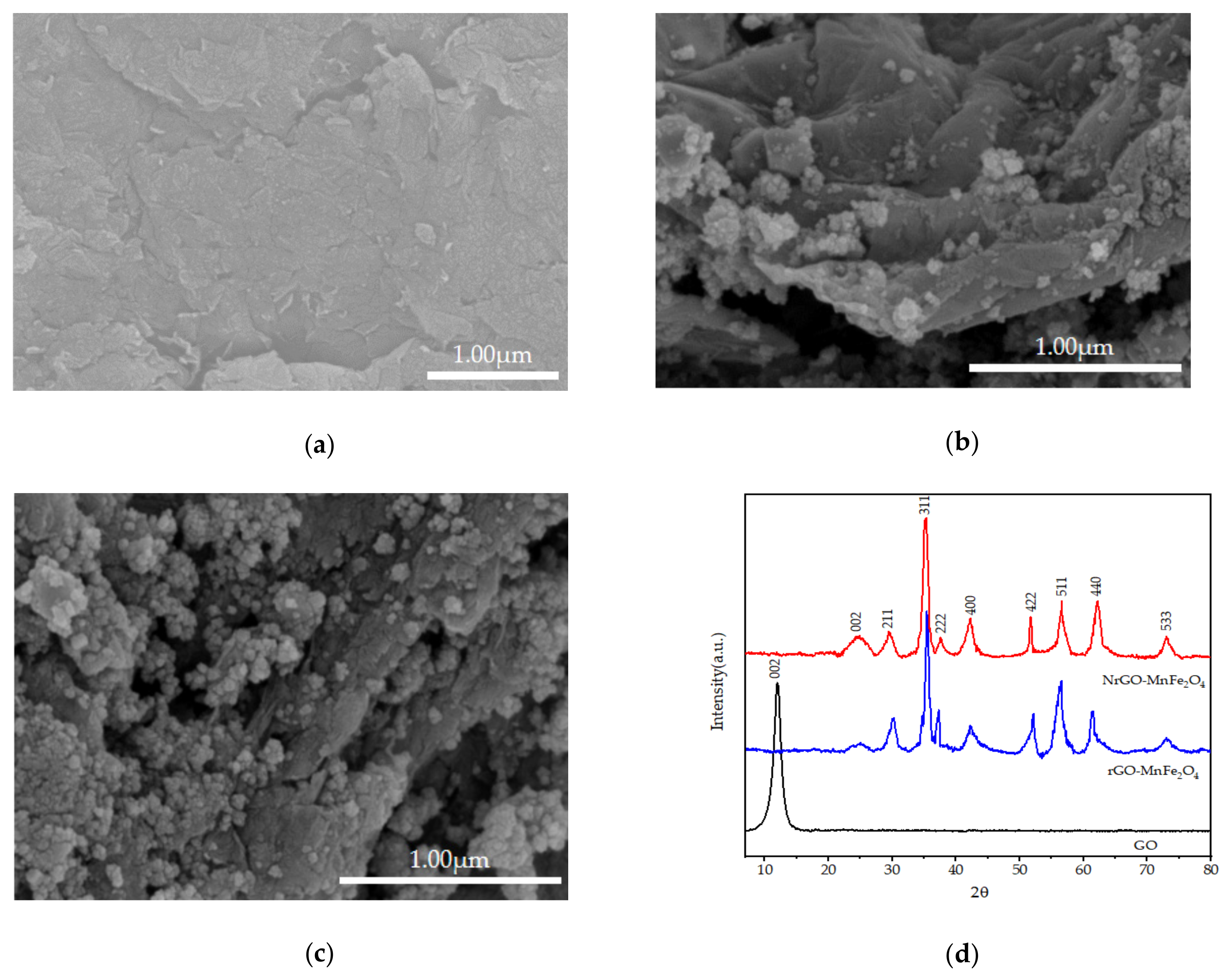
Figure 1a–c show the SEM images of GO, rGO-MnFe2O4, and NrGO-MnFe2O4. GO is a smooth lamellar structure, which is the effect of multiple layers stacked together. After modification, both rGO-MnFe2O4 and NrGO-MnFe2O4 can observe stacks and folds, which are generated during the reduction process. However, NrGO-MnFe2O4 fold degree is higher, which is caused by more peeling defects with nitrogen doping. In addition, these defects also provide a more catalytic active center. Both rGO-MnFe2O4 and NrGO-MnFe2O4 have fine particle distribution on the laminar, indicating that MnFe2O4 has been successfully loaded on the graphene surface. However, MnFe2O4 appeared as an aggregation on the surface of rGO, while it was more evenly distributed and dense on NrGO. The crystal structure of the material is further analyzed by XRD. According to Figure 1d, rGO-MnFe2O4 and NrGO-MnFe2O4 both obtained peaks consistent with the spinel phase MnFe2O4 standard atlas (JCPDS NO.10-0319), indicating that MnFe2O4 was successfully prepared. The peaks observed at 2Ɵ of 30.22°, 35.4°, 37.28°, 42.24°, 52.12°, 56.56°, 61.58°, and 73.06° represent (111), (220), (311), (222), (400), (422), (511), (440) and (533) planes, respectively. It can be seen from Figure 1d that the 2θ = 10°characteristic peak completely disappears in the XRD spectra of GO, while a new wide peak (graphene (002) planes) appears in the RGO-MnFe2O4 and NrGO-MnFe2O4 spectra, indicating its peeling and GO reduction. However, the peak corresponding to the NrGO-MnFe2O4 (002) plane is at a higher 2θ degree, indicating that doping can induce more peeling and reduction [29]. Other studies have shown that the effect of doping on the crystal structure of graphene is negligible [30].
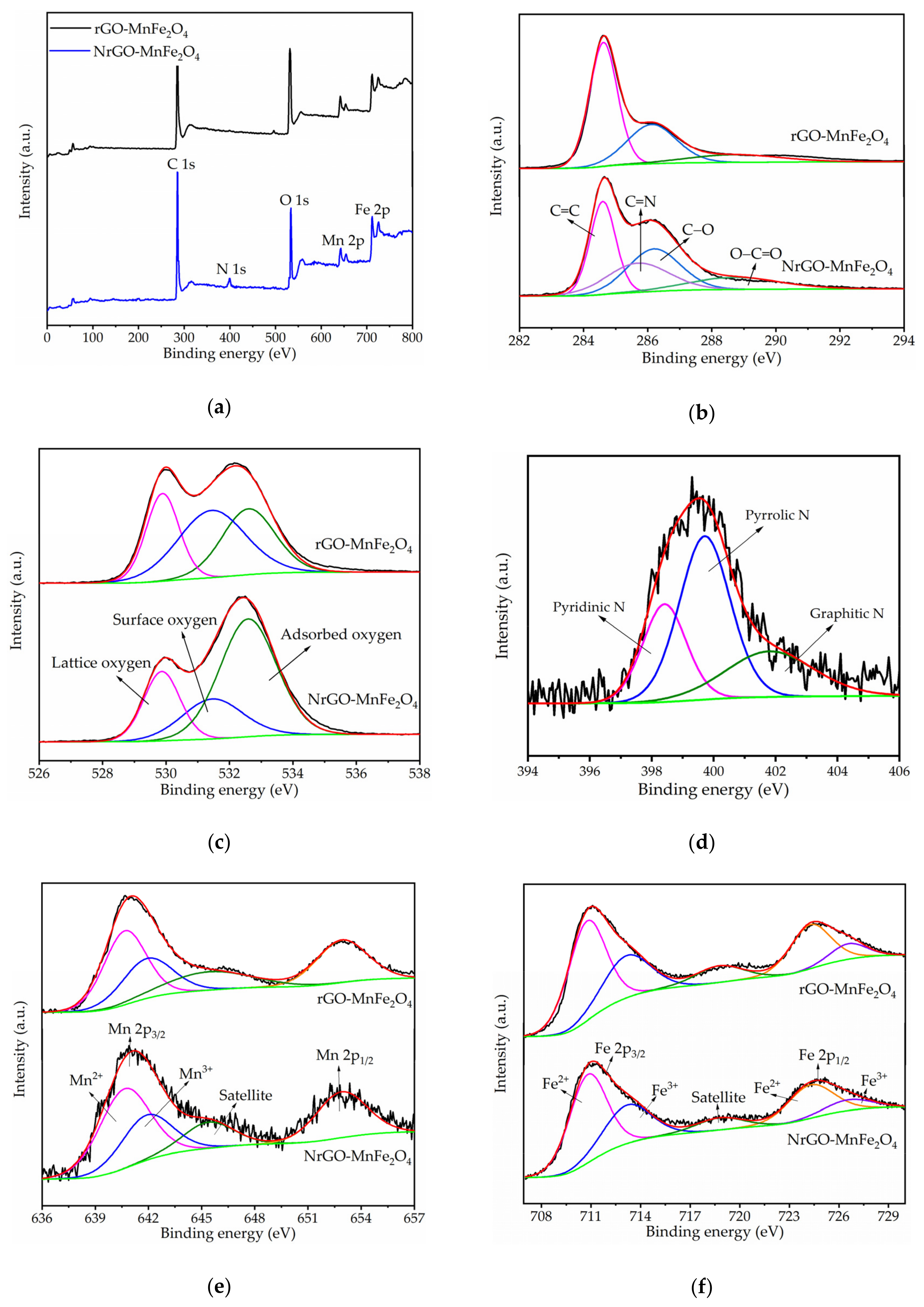
XPS was utilized to further detect the surface characteristics and chemical composition of the composite. Figure 2a shows the XPS spectra of NrGO-MnFe2O4 and rGO-MnFe2O4. In the investigation of NrGO-MnFe2O4 by wide scan XPS, there are obvious peaks in Mn, Fe, C, O and N, while no element N appears in rGO-MnFe2O4, indicating that Mn, Fe, and N have been successfully doped into graphene. According to XPS analysis of the element ratio of the composites, the C/O ratio of NrG-MnFe2O4 to rGO-MnFe2O4 is 1.35 and 1.31, respectively. Figure 2b shows the C 1s spectra of NrGO-MnFe2O4 and rGO-MnFe2O4. The C 1s peak of rGO-MnFe2O4 was divided into three sub-peaks, respectively, the C=C bond (284.60 eV), C-O bond (286.20 eV), and O-C=O (288.7 eV). The C 1s peak of NrGO-MnFe2O4 was divided into four sub-peaks. In addition to the above three peaks, the new peak at 285.70 eV was the absorption peak of the C=N bond, so the intensity of the absorption peak of the C=C bond was also reduced. As can be seen from Figure 2c, the O 1s spectra of NrGO-MnFe2O4 and rGO-MnFe2O4 are divided into three absorption peaks, namely for lattice oxygen (O2−) (529.87 eV, 529.89 eV), surface oxygen (531.46 eV, 531.44 eV), and adsorption oxygen (532.59 eV, 532.60 eV) [31]. The lattice oxygen may be the combination of O and elements Fe and Mn in iron and manganese oxides [32], surface oxygen may be the binding bond of oxygen-containing groups on the catalyst surface [33], and adsorption oxygen may absorb molecular water [34]. However, in the O 1s spectra of NrGO-MnFe2O4, the oxygen content of the surface is relatively low, which may be due to the higher reduction degree of oxygen-containing groups in the process of nitrogen doping. Figure 2d shows the N 1s spectrum of NrGO-MnFe2O4, and the N 1s peaks are fitted as three sub-peaks. Among them, 398.4 eV is the pyridine nitrogen absorption peak, 399.7 eV is the pyrrole nitrogen absorption peak, and 401.85 eV is the graphite nitrogen absorption peak [35]. Because both pyridine nitrogen and pyrrole nitrogen are nitrogen-doped forms that replace carbon atoms in graphene vacancies, whereas graphite nitrogen replaces carbon atoms in the non-vacancy lattice, it is therefore indicated that nitrogen atoms replace carbon atoms in the graphene framework, and the increase in C/O further proves that the reduction degree of NrGO-MnFe2O4 is higher. Some previous studies reported that electronegative graphitized N atoms could anodize adjacent C atoms, making the negatively charged PMS more conducive to the adsorption on the surface of catalysts. The synergism between pyridine nitrogen and carbon adjacent to vacancy can show high catalytic activity. In addition, pyrrole N can also be used as an adsorption site to promote the contact between PMS and pollutants through electrostatic adsorption of organic pollutants [22,36]. In any case, the presence of pyridine N, pyrrole N, and graphite N in the N 1s spectra suggests that the NrGO prepared may have a positive impact on the activity of the hybridized catalyst.
The Mn 2p XPS spectra of NrGO-MnFe2O4 and rGO-MnFe2O4 (Figure 2e) were pleated at 641.1 (Mn 2p3/2) and 652.9 eV (Mn 2p1/2), and the spin energy was separated to 11.8 eV. The peak of Mn 2p3/2 is located at 640.64 and 641.90 eV, which are the binding energy peaks of Mn2+ and Mn3+, respectively. The other peak is 645.4 eV, which belongs to the star peak of Mn2+ in 2p3/2 [37]. Figure 2f shows the Fe 2p XPS spectra of NrGO-MnFe2O4 and rGO-MnFe2O4. Absorption peaks at 710.8 and 713.19 eV correspond to 2p3/2 peaks of Fe2+ and Fe3+, respectively. The peaks at 724.27 and 726.56 eV can be assigned to 2p1/2 peaks of Fe2+ and Fe3+, respectively [38]. The peak at 718.78 eV belongs to the Fe3+ satellite peak [39]. According to the XPS spectra of Mn 2p and Fe 2p, nitrogen doping has negligible influence on the generation of MnFe2O4.
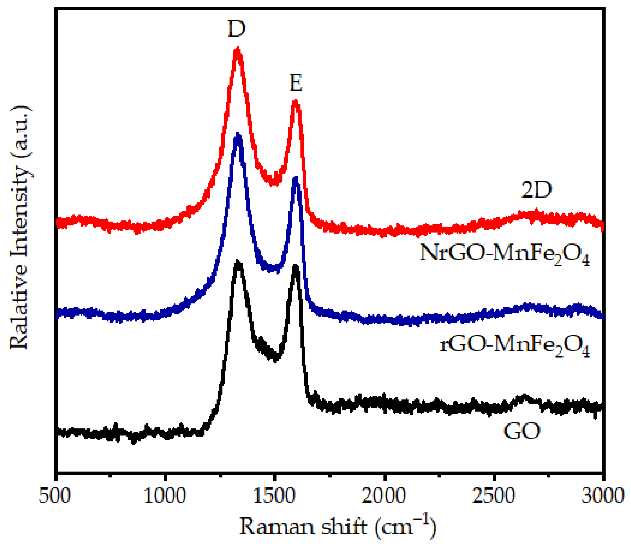
In order to further analyze the structural characteristics and properties of the materials, Raman spectroscopy was used. The D peak of graphite material in Raman spectrum comes from the vibration of graphene defects and edges and the G peak is caused by the stretching motion of sp2 hybridized atomic pairs, representing the symmetry and order degree of graphite structure. The 2D peak comes from the double phonon vibration of Raman scattering process. In general, the peak strength ratio (ID/IG) between peak D and peak G is used to measure the graphitization degree of carbon materials. The higher the ratio is, the higher the disorder degree and defect density are in the sample [40]. The Raman spectra of GO, rGO-MnFe2O4 and NrGO-MnFe2O4 are presented in Figure 3. Peak D, peak G, and peak 2D are near 1331, 1585, and 2660 cm−1, respectively. The ID /IG of GO, rGO-MnFe2O4 and NrGO-MnFe2O4 were 1.09, 1.19 and 1.33. Theoretically, when GO is reduced, the oxygen-containing functional groups are removed. The ordering degree of sp2 carbon network structure will increase, the sp2 region will become larger, and ID/IG will decrease. In fact, ID/IG increases, which may be due to the fact that after GO reduction, a large number of sp2 hybridized carbon atoms deoxidize to form new hybridized regions. These regions are smaller than GO, making the average sp2 region smaller and more numerous, which is reflected in the Raman spectrum as ID/IG ratio enhancement [41]. Compared with rGO-MnFe2O4, the ID/IG of NrGO-MnFe2O4 was significantly increased, indicating that doping of nitrogen atoms, produced more defective bits. On the one hand, more vacancies were formed. On the other hand, the difference between C-N and C-C bond distances enhanced the asymmetry of electron distribution in graphite region, further indicating the successful doping of N atoms into rGO [42].
3.2. Comparison of Different Catalytic Systems
Different electrochemical systems including EC/PMS/NrGO-MnFe2O4, EC/PMS/MnFe2O4, EC/PMS, and electrolyzation alone were used to study the LLNC. For comparison, different catalytic systems of PMS/NrGO-MnFe2O4, PMS alone and NrGO-MnFe2O4 alone were further investigated. As can be seen in Figure 4, the COD removal rate was 30.12% at 120 min in electrolysis alone process. This indicates that some pollutants are directly oxidized at the anode or oxidized by •OH generated at the anode [43,44]. However, the low removal rate might be explained by the fact that the pollutant must diffuse to the anode before oxidation, which becomes more difficult as the pollutant concentration decreases. Under the condition of adding PMS alone, the final removal rate of COD was 12.17%, which was due to the fact that PMS alone was relatively stable at normal temperature and could not decompose to produce free radicals to degrade organic matters. However, there is still COD removal, which may be caused by the small amount of transition metal ions in LLNC, which can activate PMS and produce free radical oxidation pollutants. When NrGO-MnFe2O4 was added alone, the COD removal rate was 9.21%, indicating that the catalyst had certain adsorption effect.
In EC/PMS system, COD removal rate was greater than the sum of PMS and electrolysis alone (36.29%), which was 42.33%. This suggests that electrolysis can degrade pollutants by activating PMS to generate free radicals in addition to directly oxidizing them. In addition, compared with PMS alone, the COD removal rate of the catalytic system with MnFe2O4 was significantly improved. The results show that MnFe2O4 had better ability to activate peroxosulfate and significantly improved the removal rate of pollutants [45]. Interestingly, compared with the EC/PMS/rGO-MnFe2O4 system, the COD removal rate of EC/PMS/NrGO-MnFe2O4 system has been improved to some extent, which may be caused by the following reasons: (a) the doping of nitrogen atoms forms more active centers which can activate PMS alone; (b) NrGO scaffolds greatly promote the accessibility and adsorption of substrates to active centers; (c) MnFe2O4 particles are more evenly distributed on the surface of NrGO, accelerating its activation on PMS; (d) strong electrical conductivity accelerates electron transfer between MnFe2O4 and electrode. Therefore, EC/PMS/NrGO-MnFe2O4 system is the best process to treat landfill leachate.
3.3. Factors Affectings LLNC Treatment in EC/PMS/NrGO-MnFe2O4 Process
3.3.1. Effect of pH
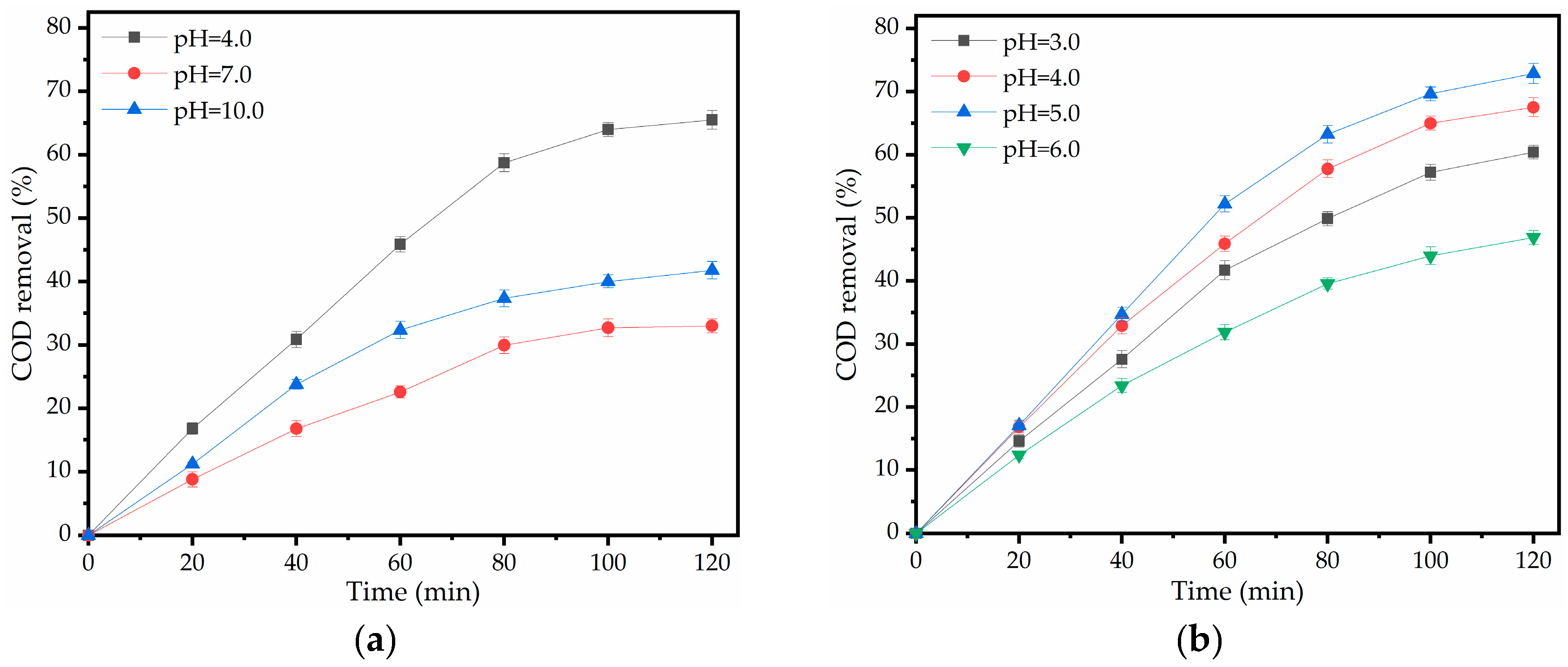
Since pH can affect the activity of catalyst and the oxidation performance of oxidant, the influence of different initial pH values on the COD removal rate in the target solution was investigated in this experiment. The results are shown in Figure 5: in the EC/PMS/NrGO-MnFe2O4 system, good removal effect was achieved within the initial pH range of 3.0~10.0 of the reaction solution, but the removal rate of COD under acidic conditions (65.53%) was slightly higher than that under neutral conditions (33.01%) and alkaline conditions (41.79%). Under acidic conditions, the effect of pH value on COD removal rate was not significant, but the best effect was obtained when pH was 5.0. Due to the fact that a high pH would precipitate metal oxides on the catalyst, some active sites on the catalyst surface were covered [46]. In addition, •OH can be generated from OH− by consuming SO4•— in large quantity under alkaline conditions (Equation (3)). The half-life of hydroxyl radicals is less than that of sulfate radicals, and the number of effectively utilized radicals is reduced [47]. Meanwhile, acidic conditions are favorable for the stable existence of sulfate radicals (Equations (3) and (4)). However, in the strong acid environment, the COD removal rate decreases. This may be due to the large increase in the number of hydrogen ions, some of which will inhibit the surface activity of the catalyst and hinder the ion circulation between iron and manganese [47]; the other part will quench sulfate and hydroxyl radicals (Equations (5) and (6)) [48].
3.3.2. Effect of NrGO-MnFe2O4 Dosage
The influence of catalyst dosage on COD removal rate in EC/PMS/NrGO-MNFe2O4 system is illustrated in Figure 6a: at a catalyst dosage of 0.25~0.75 g/L, the increase in catalyst resulted in a significant increase in COD removal rate in wastewater. This is due to the increase in active sites, which accelerates the reaction rate. However, the increased amplitude is small for a catalyst dosage of 0.75~1.0 g/L, which may be caused by the saturation of the active site [49]. In comparison, the removal rate decreased slightly when the catalyst dosage was 1.0~1.25 g/L. The reduction in removal rate may be caused by the agglomeration of nanoparticles, diffusion restriction in heterogeneous reactions and the self-annihilation of sulfate free radicals generated in a short time [50].
3.3.3. Effect of PMS Dosage
Under the optimum catalyst dosage, different PMS concentrations were detected, and the results are given in Figure 6b: with the increase in PMS concentration (0.50~2.00 mM), the COD removal rate increased from 47.59 to 72.89%. This is caused by the increase in PMS concentration and the number of free radicals generated by activation. However, when PMS concentration continued to increase to 2.50 mM, COD removal rate was lower than 2.00 mM before 80 min, then slightly higher than 2.00 mM, and finally increased to 74.39% in 120 min. This phenomenon may be due to the fact that superfluous PMS can eliminate hydroxyl radicals and sulfate radicals, and the initial reaction rate of PMS drops, as shown in Equation (7) [51]. Therefore, the removal rate was low in the first 80 min. However, with PMS at higher doses, SO5•— is generated in Equation (8). SO5•— also can oxidize and degrade pollutants, but its oxidation capacity is not as good as SO4•—. So, with the extension of the reaction time, the COD removal rate even exceeded the PMS concentration of 2.00 mM [22]. Considering this comprehensively, 2.00 mM is selected as the best concentration.
3.3.4. Effect of Current Density
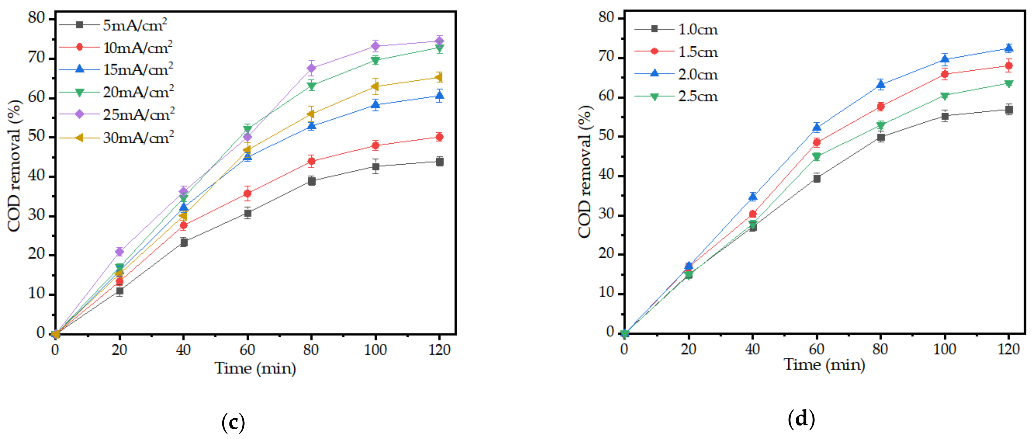
The effect of current density on COD removal rate was studied (Figure 6c). In general, the removal rate of COD gradually increases in the waste liquid, when the current density is within the range of 5~25 mA/cm2. This is mainly because the increase in current density accelerates the electron transfer rate of pollutants on the electrode surface, thus increasing the direct oxidation rate of organic pollutant molecules. Another reason is that the increase in the current density leads to more •OH (Equation (9)) and more SO4•— via electron transfer reactions on the anode surface (Equation (10)) [52]. Moreover, the electron transfer rate between iron and manganese as well as the active site on nitrogen-doped graphene can be increased, leading to the increase in NrGO-MnFe2O4 catalytic activity and the generation of more free radicals. However, when the current density increased further, the COD removal rate decreased. This phenomenon may be due to the increase in current density leading to the increase in electrode polarization, resulting in the increase in electron energy. Electrons migrate from the electrode to the solution and hydrogen evolution reaction occurs (Equation (11)) [53].
3.3.5. Effect of Electorcle Spacing
The mass transfer process of electrochemical reactor mainly includes electromigration and diffusion mass transfer, and the rates of these two mass transfer processes will be affected by the electrode plate spacing, so choosing an appropriate electrode plate spacing can promote direct oxidation and indirect oxidation. The specific results are shown in Figure 6d: with the increase in electrode spacing, COD removal first increases and then decreases, and 2 cm is the best spacing [50]. This is caused by concentration polarization caused by too-tight plate spacing, and the reduction in free migration of pollutant molecules in inter-plate solution, which affects mass transfer efficiency and leads to the reduction in electrochemical efficiency. On the contrary, if the electrode spacing is too large, the resistance will increase and the electron transfer efficiency will decrease. Moreover, too fast discharge of the electrode plate will cause too fast local reaction and insufficient degradation of organic matter, which will lead to the decrease in COD removal rate and even cause a short circuit between the electrode plates [51].
3.4. The 3D-EEM Fluorescence Spectroscopic and GC-MS Analysis on the Organic Removal
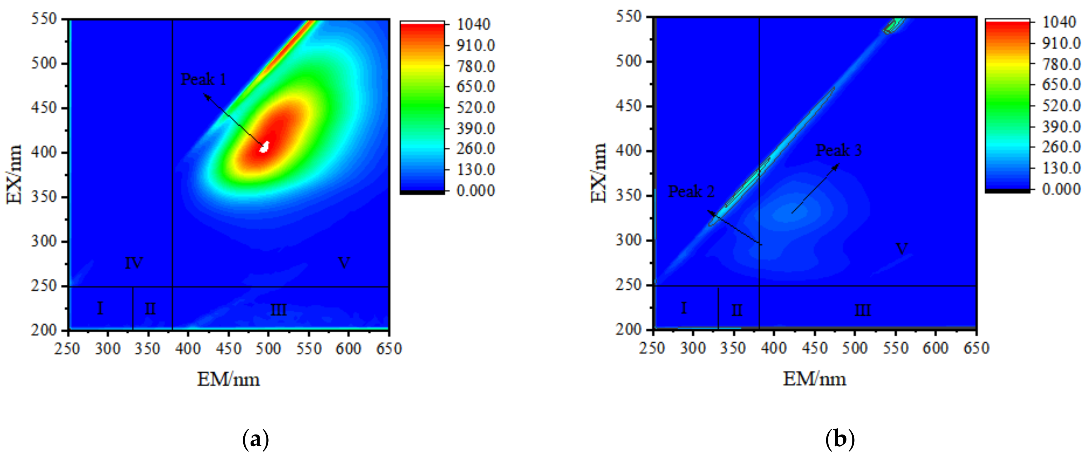
In order to explore the changes in dissolved organic matter in the treatment of LLNC by EC/PMS/NrGO-MnFe2O4 catalytic system, the 3D-EEM fluorescence spectra of the original LLNC and the effluent are shown in Figure 7. The synthesized spectrum can be subdivided into five major regions, representing aromatic protein I (I), aromatic protein II (II), fulvic acid-like samples (III), humic acid-like samples (IV) and soluble microbial by-product-like samples (V) [54]. It can be seen from Figure 7a that LLNC identified an obvious peak (peak 1) in the 3D-EEM fluorescence spectrum before treatment, and the maximum fluorescence intensity of the peak is located at the wavelength of 400/490 nm of Ex/Em, indicating that the peak belongs to humic acid-like substances. Two peaks can be roughly identified in the treated samples (Figure 7b). The first peak (peak 2) is the maximum fluorescence intensity Ex/Em wavelength at 285/410 nm, while the second peak (peak 3) is at 325/410 nm. Peak 2 and peak 3 are identified as fulvic acid-like (FA) substances widely found in landfill leachate, domestic sewage, lakes, and soils. FA generally makes a smaller molecular weight of organics and less stable chemical structure than humic acid-like substances represented by peak 1 [55]. Moreover, the fluorescence intensity of effluent was significantly lower than that of the influent, indicating that the EC/PMS/NrGO-MnFe2O4 catalytic system could degrade the macromolecules with intense fluorescence emission in LLNC and make them into substances with weak or no fluorescence characteristics.
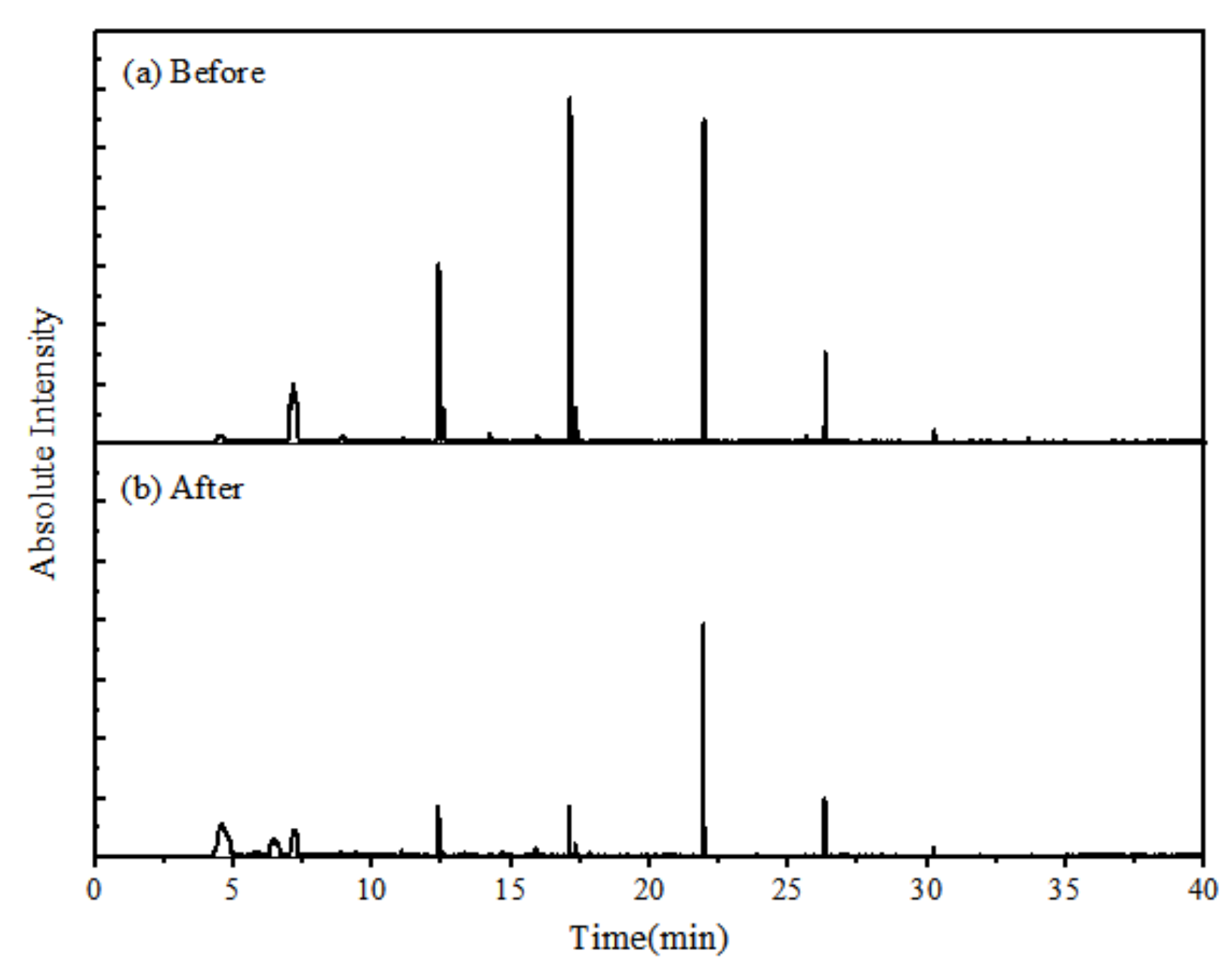
The organic pollutants in LLNC raw liquid and the treated effluent were analyzed by GC-MS. The pretreatment methods, such as extraction and rotary evaporation, were adopted. It can be seen from Figure 8 that the overall absorption abundance of organic matter in effluent LLNC decreases, indicating that the overall content of organic pollutants decreases. Moreover, a new peak appeared at the position with less time of outflow spectrum, which represented the formation of substances with simpler structure and lower molecular weight. As can be seen from Table 2 (Organic compounds of LLNC), the types and content of organic compounds in LLNC are greatly changed before and after the catalytic reaction, which further indicates that the EC/PMS/NrGO-MnFe2O4 system can effectively remove most organic compounds in LLNC. The content of silanes in the inlet water is relatively high, such as tetracycl-sevosilane, dodecycl-hexasiloxane, decycl-pentasiloxane and hexamethylcyclotrisiloxane, which may be due to the presence of SiO2 in the soil. The main chain of siloxane is Si-O-Si and there is no double bond, so it is not easily decomposed by UV light and ozone. However, the content of siloxane in the water is reduced, indicating that the EC/PMS/NrGO-MnFe2O4 system has the removal performance for it. In addition, the content of heterocycles decreased sharply, from 24.64% to 1.77%. At the same time, alkane derivatives, carboxylic acid derivatives, ketones and other compounds with small molecular weight and simple structure were generated. The analysis results of GC-MS once again demonstrate the excellent performance of the EC/PMS/NrGO-MnFe2O4 system in the treatment of LLNC.
3.5. Identification of Free Radicals in EC/PMS/NrGO-MnFe2O4 System and Possible Reaction Mechanism
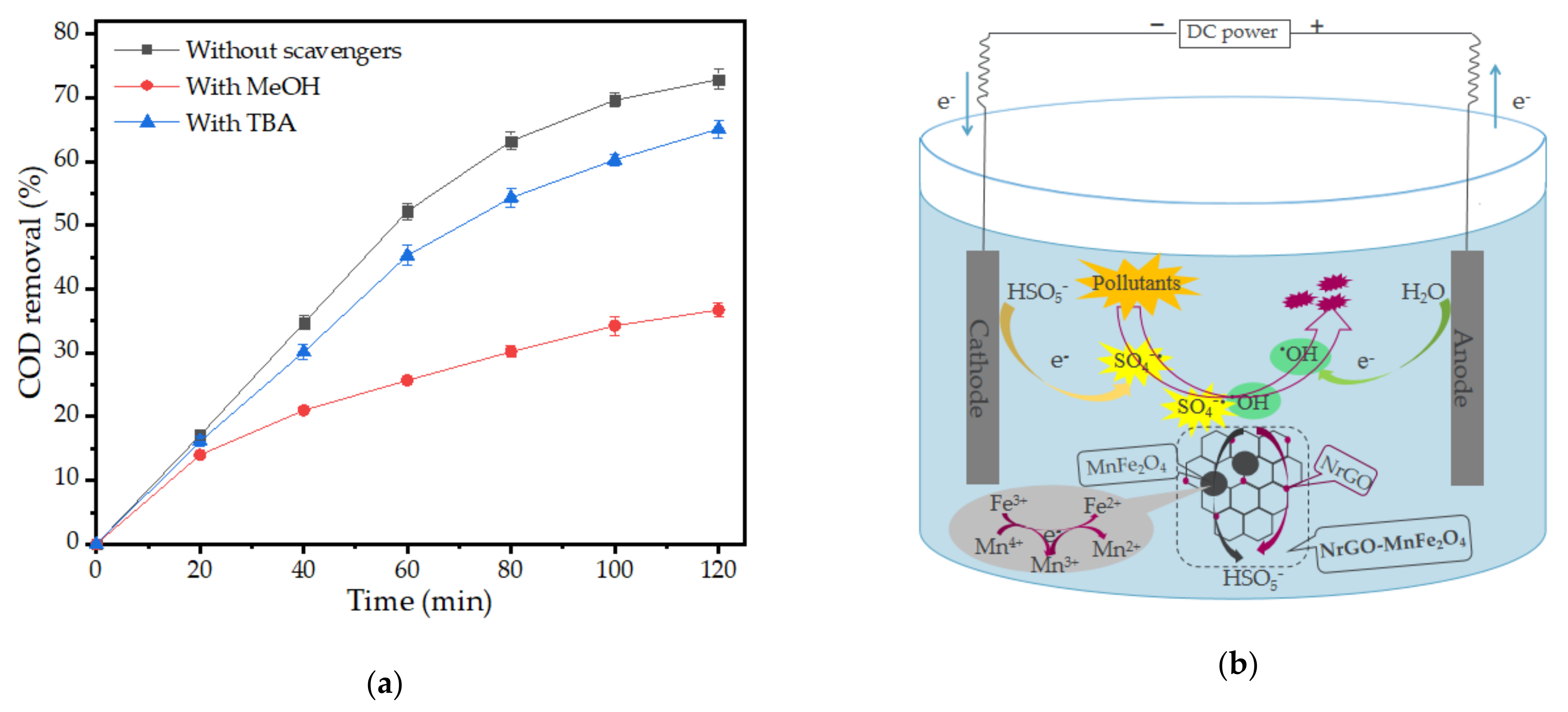
After homogeneous and heterogeneous activation, the main free radicals produced by PMS are SO4•— and •OH. In order to verify the reactive free radicals involved in the EC/PMS/NrGO-MnFe2O4 system and the difference in contributions between different free radicals, it is very necessary to carry out the free radical capture experiment. In this experiment, methanol (MeOH) and tert-butanol (TBA), two different free radical capture agents, were used. MeOH can react with SO4•— and •OH at the same time (, ). The reaction rate of TBA and •OH () was higher than that of TBA and SO4•— (), and the •OH in the system could be selectively quenched. As shown in Figure 9a, equal amounts of MeOH and TBA were added to the system for comparison. After adding MeOH, obvious inhibition was observed, while the inhibition effect brought by TBA was relatively weak. Thus, in the EC/PMS/NrGO-MnFe2O4 system, SO4•— plays a major role in the oxidative degradation of pollutants into intermediates or mineralization into inorganic salts and water, and •OH also contributes to some extent.
Based on the experiment of radical quenching, it is preliminarily speculated that the possible oxidative degradation mechanism in EC/PMS/NrGO-MnFe2O4 system is as follows (Figure 9b). First, the nitrogen-doped graphene matrix provides specific absorption domains for PMS and pollutants through chemical adsorption and π–π bond interactions, respectively, resulting in a high concentration of reactants around NrGO-MnFe2O4. Secondly, MnFe2O4 and NrGO jointly showed catalytic activity on PMS and produced rich free radicals (Equations (4) and (12)–(17)). Among them, the synergistic effect of Fe-Mn bimetals can promote the catalytic process, mainly reflected in Mn2+, Mn3+ and Fe2+, which all provide electrons to PMS and generate active free radicals through Equations (12)–(14); meanwhile, Mn3+ and Mn4+ can also be electronically reduced to Mn2+ and Mn3+ (Equations (15)–(17)), so as to realize the redox cycle of iron and manganese ions. Secondly, electrochemistry, on the one hand, treats wastewater by direct electrolysis (Equations (1) and (2)), and on the other hand, accelerates NrGO-MnFe2O4 electron transfer by providing electrons to facilitate the catalytic process (Equations (18)–(20)). Finally, under the joint action of NrGO, MnFe2O4 and electrochemistry, PMS was activated to produce rich active substances, and the organic pollutants adsorbed were oxidized and degraded into small molecules, and the release occupied point was used as the free point for the next round of reaction.
3.6. The Stability of rGO-MnFe2O4 and NrGO-MnFe2O4
For catalytic experiments, recyclability is one of the most important properties of catalysts. Therefore, the catalytic cycle experiments were carried out respectively for NrGO-MnFe2O4 and rGO-MnFe2O4 (Figure 10). Under the same experimental conditions, after six experiments, NrGO-MnFe2O4 and rGO-MnFe2O4 still have good catalytic activity, but the reduction of rGO-MnFe2O4 is greater than that of NrGO-MnFe2O4. This may be due to the catalytic effect of the active sites formed by nitrogen doping. In addition, the structure of NrGO-MnFe2O4 is more stable than that of rGO-MnFe2O4.
4. Conclusions
LLNC was treated by electrochemical method combined with PMS/NrGO-MnFe2O4 method, and the main conclusions were as follows:
- NrGO-MnFe2O4 and rGO-MnFe2O4 particles with magnetic cycling ability were prepared in one step by simple hydrothermal method, and were characterized by SEM, XRD, RAMAN and XPS. Through comparison, it was found that NrGO-MnFe2O4 formed more active centers due to nitrogen doping, causing: (a) more defects, which were used to activate PMS and greatly promoted the accessibility and adsorption of substrates to the active centers; (b) more conductivity to uniform magnetic particle load; (c) stronger electrical conductivity, making it conducive to electron transfer in the catalytic process. NrGO-MnFe2O4 is more suitable as a catalyst for the EC/PMS system. Through the catalyst cycle experiment, it was found that NrGO-MnFe2O4 has better secondary cycle performance than rGO-MnFe2O4.
- In the comparison of catalytic systems, EC/PMS/NrGO-MnFe2O4 process shows the advantages of electrochemical coupling of NrGO and MnFe2O4 in the treatment of LLNC refractory wastewater. The operating conditions were optimized by single factor analysis experiments, with initial pH of 5.0, NrGO-MnFe2O4 dose of 1.0 g/L, PMS dose of 2.0 mm, current density of 25 mA/cm2 and plate spacing of 2.0 cm. Under the best conditions, the COD removal rate of LLNC can reach 72.89% after 120 min.
- The 3D-EEM fluorescence and GC-MS analysis of LLNC before and after treatment showed that EC/PMS/NrGO-MnFe2O4 could effectively treat LLNC, a kind of refractory wastewater. Combined with the radical quenching experiment, it was found that PMS mainly generated SO4•— and •OH under the combined action of electrochemistry and NrGO-MnFe2O4. Thus, most macromolecules, such as heterocyclic macromolecules in wastewater, can be effectively removed and degraded into small molecular weight intermediates.
In conclusion, this study provided an efficient, easily prepared, and recyclable catalyst NrGO-MnFe2O4, and reduced its combination with electrochemistry, promoting the development of advanced oxidation technology based on PMS to treat refractory biodegradable wastewater.
Author Contributions
Conceptualization, J.W. and Z.H.; methodology, J.W.; software, J.W.; validation, J.W., Y.W. and M.L.; formal analysis, J.W.; investigation, J.W.; resources, Z.H.; data curation, J.W.; writing—original draft preparation, J.W.; writing—review and editing, Z.H.; visualization, J.W.; supervision, Z.H.; project administration, Z.H.; funding acquisition, Z.H. All authors have read and agreed to the published version of the manuscript.
Funding
This work was financially supported by China’s National Key Project of Science and Technology (No. 2017ZX07602-001-002).
Institutional Review Board Statement
Not applicable.
Informed Consent Statement
Not applicable.
Data Availability Statement
The data presented in this study are available on request from the corresponding author. The data are not publicly available due to privacy.
Conflicts of Interest
The authors declare no conflict of interest.
References
- Chen, W.; Luo, Y.; Ran, G.; Li, Q. An investigation of refractory organics in membrane bioreactor effluent following the treatment of landfill leachate by the O3/H2O2 and MW/PS processes. Waste Manag. 2019, 97, 1–9. [Google Scholar] [CrossRef]
- Koshy, L.; Paris, E.; Ling, S.; Jones, T.; Bérubé, K.A. Bioreactivity of leachate from municipal solid waste landfills—Assessment of toxicity. Sci. Total. Environ. 2007, 384, 171–181. [Google Scholar] [CrossRef]
- Long, Y.; Xu, J.; Shen, D.; Du, Y.; Feng, H.J. Effective removal of contaminants in landfill leachate membrane concentrates by coagulation. Chemosphere 2017, 167, 512–519. [Google Scholar] [CrossRef]
- Fernandes, A.; Labiadh, L.; Ciríaco, L.; Pacheco, M.; Gadri, A.; Ammar, S.; Lopes, A. Electro-Fenton oxidation of reverse osmosis concentrate from sanitary landfill leachate: Evaluation of operational parameters. Chemosphere 2017, 184, 1223–1229. [Google Scholar] [CrossRef] [PubMed]
- Zhou, B.; Yu, Z.; Wei, Q.; Long, H.; Xie, Y.; Wang, Y. Electrochemical oxidation of biological pretreated and membrane separated landfill leachate concentrates on boron doped diamond anode. Appl. Surf. Sci. 2016, 377, 406–415. [Google Scholar] [CrossRef]
- Hu, Y.; Lu, Y.; Liu, G.; Luo, H.; Zhang, R.; Cai, X. Effect of the structure of stacked electro-Fenton reactor on treating nanofiltration concentrate of landfill leachate. Chemosphere 2018, 202, 191–197. [Google Scholar] [CrossRef] [PubMed]
- Zhao, J.; Ouyang, F.; Yang, Y.; Tang, W. Degradation of recalcitrant organics in nanofiltration concentrate from biologically pretreated landfill leachate by ultraviolet-Fenton method. Sep. Purif. Technol. 2020, 235, 116076. [Google Scholar] [CrossRef]
- Liang, S.-X.; Jia, Z.; Liu, Y.-J.; Zhang, W.; Wang, W.; Lu, J.; Zhang, L.-C. Compelling Rejuvenated Catalytic Performance in Metallic Glasses. Adv. Mater. 2018, 30, e1802764. [Google Scholar] [CrossRef] [Green Version]
- Guo, S.; Wang, H.; Yang, W.; Fida, H.; You, L.; Zhou, K. Scalable synthesis of Ca-doped α-Fe2O3 with abundant oxygen vacancies for enhanced degradation of organic pollutants through peroxymonosulfate activation. Appl. Catal. B Environ. 2020, 262, 118250. [Google Scholar] [CrossRef]
- Sun, Z.; Li, S.; Ding, H.; Zhu, Y.; Wang, X.; Liu, H.; Zhang, Q.; Zhao, C. Electrochemical/Fe3+/peroxymonosulfate system for the degradation of Acid Orange 7 adsorbed on activated carbon fiber cathode. Chemosphere 2020, 241, 125125. [Google Scholar] [CrossRef]
- Li, J.; Lin, H.; Zhu, K.; Zhang, H. Degradation of Acid Orange 7 using peroxymonosulfate catalyzed by granulated activated carbon and enhanced by electrolysis. Chemosphere 2017, 188, 139–147. [Google Scholar] [CrossRef]
- Zhang, X.; Yao, J.; Zhao, Z.; Liu, J. Degradation of haloacetonitriles with UV/peroxymonosulfate process: Degradation pathway and the role of hydroxyl radicals. Chem. Eng. J. 2019, 364, 1–10. [Google Scholar] [CrossRef]
- Wei, M.; Gao, L.; Li, J.; Fang, J.; Cai, W.; Li, X.; Xu, A. Activation of peroxymonosulfate by graphitic carbon nitride loaded on activated carbon for organic pollutants degradation. J. Hazard. Mater. 2016, 316, 60–68. [Google Scholar] [CrossRef]
- Gu, X.; Wang, Y.; Miao, Z.; Lyu, S.; Qiu, Z.; Sui, Q.; Guo, X. Degradation of trichloroethylene in aqueous solution by persulfate activated with Fe(III)–EDDS complex. Res. Chem. Intermed. 2017, 43, 1–13. [Google Scholar] [CrossRef]
- Liang, S.-X.; Wang, X.; Zhang, W.; Liu, Y.-J.; Wang, W.; Zhang, L.-C. Selective laser melting manufactured porous Fe-based metallic glass matrix composite with remarkable catalytic activity and reusability. Appl. Mater. Today 2020, 19, 100543. [Google Scholar] [CrossRef]
- Yangab, Y.; Liab, Y.; Hongab, P.; Wua, Z.; Xiea, C.; Zhanga, K.; Lianxiangc, L.; Hea, J.; Konga, L.; Liua, J. Surface-active MnFeO@C cubes as enhanced peroxymonosulfate activators for efficient degradation of bisphenol A. Appl. Surf. Sci. 2021, 538, 148008. [Google Scholar] [CrossRef]
- Galindo, R.; Menéndez-González, N.; Crespo, P.; Velasco, V.; Bomatí-Miguel, O.; Diaz-Fernandez, D.; Herrasti, P. Comparison of different methodologies for obtaining nickel nanoferrites. J. Magn. Magn. Mater. 2014, 361, 118–125. [Google Scholar] [CrossRef]
- Hu, M.; Yao, Z.; Wang, X. Graphene-Based Nanomaterials for Catalysis. Ind. Eng. Chem. Res. 2017, 56, 3477–3502. [Google Scholar] [CrossRef]
- Primo, A.; Neatu, F.; Florea, M.; Parvulescu, V.; Garcia, H. Graphenes in the absence of metals as carbocatalysts for selective acetylene hydrogenation and alkene hydrogenation. Nat. Commun. 2014, 5, 5291. [Google Scholar] [CrossRef] [Green Version]
- Duan, X.; O’Donnell, K.; Sun, H.; Wang, Y.; Wang, S. Sulfur and Nitrogen Co-Doped Graphene for Metal-Free Catalytic Oxidation Reactions. Small 2015, 11, 3036–3044. [Google Scholar] [CrossRef] [Green Version]
- Li, R.; Wei, Z.; Gou, X. Nitrogen and Phosphorus Dual-Doped Graphene/Carbon Nanosheets as Bifunctional Electrocatalysts for Oxygen Reduction and Evolution. ACS Catal. 2015, 5, 4133–4142. [Google Scholar] [CrossRef]
- Zhang, T.; Li, C.; Sun, X.; Gao, H.; Liu, X.; Sun, J.; Shi, W.; Ai, S. Iron nanoparticles encapsulated within nitrogen and sulfur co-doped magnetic porous carbon as an efficient peroxymonosulfate activator to degrade 1-naphthol. Sci. Total. Environ. 2020, 739, 139896. [Google Scholar] [CrossRef]
- Liang, S.; Jia, Z.; Zhang, L.; Li, X.; Wang, W.-M.; Lin, H. Ultrafast activation efficiency of three peroxides by Fe78Si9B13 metallic glass under photo-enhanced catalytic oxidation: A comparative study. Appl. Catal. B Environ. 2018, 221, 108–118. [Google Scholar] [CrossRef]
- Zhang, Y.; Kang, W.; Yu, H.; Chen, S.; Quan, X. Electrochemical activation of peroxymonosulfate in cathodic micro-channels for effective degradation of organic pollutants in wastewater. J. Hazard. Mater. 2020, 398, 122879. [Google Scholar] [CrossRef]
- Kafshgari, L.A.; Ghorbani, M.; Azizi, A. Fabrication and investigation of MnFe2O4/MWCNTs nanocomposite by hydrothermal technique and adsorption of cationic and anionic dyes. Appl. Surf. Sci. 2017, 419, 70–83. [Google Scholar] [CrossRef]
- Kafshgari, L.A.; Ghorbani, M.; Azizi, A.; Agarwal, S.; Gupta, V.K. Modeling and optimization of Direct Red 16 adsorption from aqueous solutions using nanocomposite of MnFe2O4 /MWCNTs: RSM-CCRD model. J. Mol. Liq. 2017, 233, 370–377. [Google Scholar] [CrossRef]
- Guvenc, S.Y.; Dincer, K.; Varank, G. Performance of electrocoagulation and electro-Fenton processes for treatment of nanofiltration concentrate of biologically stabilized landfill leachate. J. Water Process. Eng. 2019, 31, 100863. [Google Scholar] [CrossRef]
- Amaral-Silva, N.; Martins, R.C.; Castro-Silva, S.; Quinta-Ferreira, R.M. Ozonation and perozonation on the biodegradability improvement of a landfill leachate. J. Environ. Chem. Eng. 2016, 4, 527–533. [Google Scholar] [CrossRef]
- Gao, H.; Li, R.; He, W.; Guo, R.; Chai, B. One-step synthesis of reduced graphene oxide supported Pt naoparticles and its electrocatalytic activity for methanol oxidation. Acta Phys. Chim. Sin. 2015, 33, 2117–2123. [Google Scholar] [CrossRef]
- Yuan, B.; Xing, W.; Hu, Y.; Mu, X.; Wang, J.; Tai, Q.; Li, G.; Liu, L.; Liew, K.M.; Hu, Y. Boron/phosphorus doping for retarding the oxidation of reduced graphene oxide. Carbon 2016, 101, 152–158. [Google Scholar] [CrossRef]
- Qin, W.; Fang, G.; Wang, Y.; Zhou, D. Mechanistic understanding of polychlorinated biphenyls degradation by peroxymonosulfate activated with CuFe2O4 nanoparticles: Key role of superoxide radicals. Chem. Eng. J. 2018, 348, 526–534. [Google Scholar] [CrossRef]
- Tang, W.; Su, Y.; Li, Q.; Gao, S.; Shang, J.K. Superparamagnetic magnesium ferrite nanoadsorbent for effective arsenic (III, V) removal and easy magnetic separation. Water Res. 2013, 47, 3624–3634. [Google Scholar] [CrossRef]
- Xiao, J.; Xu, G.; Sun, S.-G.; Meng, X. MFe2O4 and MFe@Oxide Core-Shell Nanoparticles Anchored on N-Doped Graphene Sheets for Synergistically Enhancing Lithium Storage Performance and Electrocatalytic Activity for Oxygen Reduction Reactions. Part. Part. Syst. Charact. 2013, 30, 893–904. [Google Scholar] [CrossRef]
- Merino, N.A.; Barbero, B.P.; Eloy, P.; Cadús, L.E. La1−xCaxCoO3 perovskite-type oxides: Identification of the surface oxygen species by XPS. Appl. Surf. Sci. 2006, 253, 1489–1493. [Google Scholar] [CrossRef]
- Zheng, W.; Xiao, X.; Chen, B. A nonradical reaction-dominated phenol degradation with peroxydisulfate catalyzed by nitrogen-doped graphene. Sci. Total. Environ. 2019, 667, 287–296. [Google Scholar] [CrossRef]
- Long, Y.; Huang, Y.; Wu, H.; Shi, X.; Xiao, L. Peroxymonosulfate activation for pollutants degradation by Fe-N-codoped carbonaceous catalyst: Structure-dependent performance and mechanism insight. Chem. Eng. J. 2019, 369, 542–552. [Google Scholar] [CrossRef]
- Fan, J.; Qin, H.; Jiang, S. Mn-doped g-C3N4 composite to activate peroxymonosulfate for acetaminophen degradation: The role of superoxide anion and singlet oxygen. Chem. Eng. J. 2019, 359, 723–732. [Google Scholar] [CrossRef]
- Liao, X.; Wang, F.; Cai, Y.; Yao, Y.; Teng, B.-T.; Hao, Q.; Lu, S. Synthesis of (100) surface oriented MIL-88A-Fe with rod-like structure and its enhanced fenton-like performance for phenol removal. Appl. Catal. B Environ. 2019, 259, 118064. [Google Scholar] [CrossRef]
- Zhu, C.; Liu, Y.; Huo, C.; Liu, H. Enhancing the light olefin selectivity of an iron-based Fischer–Tropsch synthesis catalyst by modification with CTAB. RSC Adv. 2018, 8, 32073–32083. [Google Scholar] [CrossRef] [Green Version]
- Pachfule, P.; Shinde, D.; Majumder, D.S.M.; Xu, P.P.Q. Fabrication of carbon nanorods and graphene nanoribbons from a metal–organic framework. Nat. Chem. 2016, 8, 718–724. [Google Scholar] [CrossRef]
- Zeng, T.; Zhang, H.; He, Z.; Chen, J.; Song, S. Mussel-inspired approach to constructing robust cobalt-embedded N-doped carbon nanosheet toward enhanced sulphate radical-based oxidation. Sci. Rep. 2016, 6, 33348. [Google Scholar] [CrossRef] [Green Version]
- Chen, X.; Duan, X.; Oh, W.-D.; Zhang, P.-H.; Guan, C.-T.; Zhu, Y.-A.; Lim, T.-T. Insights into nitrogen and boron-co-doped graphene toward high-performance peroxymonosulfate activation: Maneuverable N-B bonding configurations and oxidation pathways. Appl. Catal. B Environ. 2019, 253, 419–432. [Google Scholar] [CrossRef]
- Bagastyo, A.Y.; Radjenovic, J.; Mu, Y.; Rozendal, R.A.; Batstone, D.J.; Rabaey, K. Electrochemical oxidation of reverse osmosis concentrate on mixed metal oxide (MMO) titanium coated electrodes. Water Res. 2011, 45, 4951–4959. [Google Scholar] [CrossRef] [PubMed]
- Yang, Y.; Pignatello, J.J.; Ma, J.; Mitch, W.A. Effect of matrix components on UV/H2O2 and UV/S2O82− advanced oxidation processes for trace organic degradation in reverse osmosis brines from municipal wastewater reuse facilities. Water Res. 2016, 89, 192–200. [Google Scholar] [CrossRef] [PubMed] [Green Version]
- Deng, J.; Xu, M.; Qiu, C.; Chen, Y.; Ma, X.; Gao, N.; Li, X. Magnetic MnFe2O4 activated peroxymonosulfate processes for degradation of bisphenol A: Performance, mechanism and application feasibility. Appl. Surf. Sci. 2018, 459, 138–147. [Google Scholar] [CrossRef]
- Leng, Y.; Guo, W.; Shi, X.; Li, Y.; Wang, A.; Hao, F.; Xing, L. Degradation of Rhodamine B by persulfate activated with Fe3O4: Effect of polyhydroquinone serving as an electron shuttle. Chem. Eng. J. 2014, 240, 338–343. [Google Scholar] [CrossRef]
- Oh, W.-D.; Dong, Z.; Lim, T.-T. Generation of sulfate radical through heterogeneous catalysis for organic contaminants removal: Current development, challenges and prospects. Appl. Catal. B Environ. 2016, 194, 169–201. [Google Scholar] [CrossRef]
- Guan, Y.-H.; Ma, J.; Li, X.-C.; Fang, J.; Chen, L.-W. Influence of pH on the Formation of Sulfate and Hydroxyl Radicals in the UV/Peroxymonosulfate System. Environ. Sci. Technol. 2011, 45, 9308–9314. [Google Scholar] [CrossRef] [PubMed]
- Du, J.; Bao, J.; Liu, Y.; Kim, S.H.; Dionysiou, D.D. Facile preparation of porous Mn/Fe3O4 cubes as peroxymonosulfate activating catalyst for effective bisphenol A degradation. Chem. Eng. J. 2019, 376, 119193. [Google Scholar] [CrossRef]
- Liu, J.; Zhao, Z.; Shao, P.; Cui, F. Activation of peroxymonosulfate with magnetic Fe3O4–MnO2 core–shell nanocomposites for 4-chlorophenol degradation. Chem. Eng. J. 2015, 262, 854–861. [Google Scholar] [CrossRef]
- Deng, J.; Feng, S.; Ma, X.; Tan, C.; Wang, H.; Zhou, S.; Zhang, T.; Li, J.; Ni, Y.; Lu, Y. Heterogeneous degradation of Orange II with peroxymonosulfate activated by ordered mesoporous MnFe2O4. Sep. Purif. Technol. 2016, 167, 181–189. [Google Scholar] [CrossRef]
- Lin, H.; Zhang, H.; Hou, L. Degradation of C. I. Acid Orange 7 in aqueous solution by a novel electro/Fe3O4/PDS process. J. Hazard. Mater. 2014, 276, 182–191. [Google Scholar] [CrossRef] [PubMed]
- Xue, W.-J.; Cui, Y.-H.; Liu, Z.-Q.; Yang, S.-Q.; Li, J.-Y.; Guo, X.-L. Treatment of landfill leachate nanofiltration concentrate after ultrafiltration by electrochemically assisted heat activation of peroxydisulfate. Sep. Purif. Technol. 2020, 231, 115928. [Google Scholar] [CrossRef]
- Ma, C.; He, Z.; Jia, S.; Zhang, X.; Hou, S. Treatment of stabilized landfill leachate by Fenton-like process using Fe3O4 particles decorated Zr-pillared bentonite. Ecotoxicol. Environ. Saf. 2018, 161, 489–496. [Google Scholar] [CrossRef]
- Wang, Z.; Li, J.; Tan, W.; Wu, X.; Lin, H.; Zhang, H. Removal of COD from landfill leachate by advanced Fenton process combined with electrolysis. Sep. Purif. Technol. 2019, 208, 3–11. [Google Scholar] [CrossRef]
Figure 1.
SEM images of (a) GO, (b) rGO-MnFe2O4, and (c) NrGO-MnFe2O4; (d) XRD spectra of GO, rGO-MnFe2O4, and NrGO-MnFe2O4.
Figure 1.
SEM images of (a) GO, (b) rGO-MnFe2O4, and (c) NrGO-MnFe2O4; (d) XRD spectra of GO, rGO-MnFe2O4, and NrGO-MnFe2O4.

Figure 2.
(a) XPS spectra of rGO-MnFe2O4 and NrGO-MnFe2O4; (b) C 1s scan, (c) O 1s scan, (d) N 1s scan, (e) Mn 2p scan and (f) Fe 2p scan of rGO-MnFe2O4 and NrGO-MnFe2O4.
Figure 2.
(a) XPS spectra of rGO-MnFe2O4 and NrGO-MnFe2O4; (b) C 1s scan, (c) O 1s scan, (d) N 1s scan, (e) Mn 2p scan and (f) Fe 2p scan of rGO-MnFe2O4 and NrGO-MnFe2O4.

Figure 3.
Raman spectra of GO, rGO-MnFe2O4 and NrGO-MnFe2O4.

Figure 4.
Chemical oxygen demand (COD) removal rates of different systems. Reaction conditions: pH of 5.0; catalytic dosage of 1.00 g/L; peroxymonosulfate (PMS) dosage of 2.00 mM; current density of 20 mA/cm2; electorcle spacing of 2.0 cm.
Figure 4.
Chemical oxygen demand (COD) removal rates of different systems. Reaction conditions: pH of 5.0; catalytic dosage of 1.00 g/L; peroxymonosulfate (PMS) dosage of 2.00 mM; current density of 20 mA/cm2; electorcle spacing of 2.0 cm.

Figure 5.
Effect of initial pH on the removal of COD in the LLNC: (a) pH = 4.0, 7.0, and 10.0; (b) pH = 3.0, 4.0, 5.0, and 6.0. Reaction conditions: catalytic dosage of 1.00 g/L; PMS dosage of 2.00 mM; current density of 20 mA/cm2; electorcle spacing of 2.0 cm.
Figure 5.
Effect of initial pH on the removal of COD in the LLNC: (a) pH = 4.0, 7.0, and 10.0; (b) pH = 3.0, 4.0, 5.0, and 6.0. Reaction conditions: catalytic dosage of 1.00 g/L; PMS dosage of 2.00 mM; current density of 20 mA/cm2; electorcle spacing of 2.0 cm.

Figure 6.
Effect of NrGO-MnFe2O4 dosage (a), PMS dosage (b), current density (c), and electorcle spacing (d) on the removal of COD in the LLNC. Reaction conditions: pH of 5.0; catalytic dosage of 1.00 g/L; PMS dosage of 2.00 mM; current density of 20 mA/cm2; electorcle spacing of 2.0 cm.
Figure 6.
Effect of NrGO-MnFe2O4 dosage (a), PMS dosage (b), current density (c), and electorcle spacing (d) on the removal of COD in the LLNC. Reaction conditions: pH of 5.0; catalytic dosage of 1.00 g/L; PMS dosage of 2.00 mM; current density of 20 mA/cm2; electorcle spacing of 2.0 cm.


Figure 7.
Three-dimensional EEM fluorescence spectra of treated LLNC before (a) and after (b).

Figure 8.
The GC-MS analysis on treated LLNC before (a) and after (b).

Figure 9.
Effects of different quenchers (a): tert-butanol (TBA) (100mM) and methanol (MeOH) (100 mM), on COD removal rate (reaction conditions: pH of 5.0; catalytic dosage of 1.00 g/L; PMS dosage of 2.00 mM; current density of 20 mA/cm2; electorcle spacing of 2.0 cm), and possible reaction mechanism (b).

Figure 10.
Effect of recycling catalyst ((a) NrGO-MnFe2O4; (b) rGO-MnFe2O4) on COD removal.


Table 1.
Characteristics of the target solution (landfill leachate nanofiltration concentration, LLNC).
Table 1.
Characteristics of the target solution (landfill leachate nanofiltration concentration, LLNC).
| Parameter | Unit | Concentration |
|---|---|---|
| pH | - | 8.3 ± 0.5 |
| COD | mg/L | 1250 ± 67 |
| BOD5 | mg/L | 54 ± 8 |
| NH3-N | mg/L | 30 ± 3 |
| NO3-N | mg/L | 647 ± 12 |
| NO2-N | mg/L | 8 ± 0.5 |
| TN | mg/L | 733 ± 15 |
Data presented are mean ± standard error.
Table 2.
Organic compounds of LLNC.
| Organic Compounds | Influent Values | Effluent Values | ||
|---|---|---|---|---|
| Type | Percentage (%) | Types | Percentage (%) | |
| Alcohols | 1 | 3.44 | 0 | 0 |
| Heterocyclic compounds | 3 | 24.64 | 1 | 1.77 |
| Aromatic hydrocarbon | 1 | 1.14 | 1 | 0.98 |
| Esters | 1 | 1.06 | 2 | 1.48 |
| Phenolic compounds | 1 | 0.89 | 0 | 0 |
| Siloxanes | 4 | 68.83 | 6 | 44.51 |
| Carboxylic acid derivatives | 0 | 0 | 1 | 34.71 |
| Alkane derivatives | 0 | 0 | 2 | 14.08 |
| Cycloalkanes | 0 | 0 | 1 | 0.77 |
| Aldehydes derivatives | 0 | 0 | 1 | 0.86 |
| Ketone derivatives | 0 | 0 | 1 | 0.84 |
Publisher’s Note: MDPI stays neutral with regard to jurisdictional claims in published maps and institutional affiliations. |
© 2021 by the authors. Licensee MDPI, Basel, Switzerland. This article is an open access article distributed under the terms and conditions of the Creative Commons Attribution (CC BY) license (http://creativecommons.org/licenses/by/4.0/).
Share and Cite
MDPI and ACS Style
Wang, J.; He, Z.; Wang, Y.; Lu, M. Electrochemical/Peroxymonosulfate/NrGO-MnFe2O4 for Advanced Treatment of Landfill Leachate Nanofiltration Concentrate. Water 2021, 13, 413. https://doi.org/10.3390/w13040413
AMA Style
Wang J, He Z, Wang Y, Lu M. Electrochemical/Peroxymonosulfate/NrGO-MnFe2O4 for Advanced Treatment of Landfill Leachate Nanofiltration Concentrate. Water. 2021; 13(4):413. https://doi.org/10.3390/w13040413
Chicago/Turabian StyleWang, Jiaqi, Zhengguang He, Yuzhong Wang, and Manjing Lu. 2021. "Electrochemical/Peroxymonosulfate/NrGO-MnFe2O4 for Advanced Treatment of Landfill Leachate Nanofiltration Concentrate" Water 13, no. 4: 413. https://doi.org/10.3390/w13040413
Note that from the first issue of 2016, this journal uses article numbers instead of page numbers. See further details here.