
Numerical Analysis on the Heat Transfer Characteristics of Supercritical Water in Vertically Upward Internally Ribbed Tubes

State Key Laboratory of Multiphase Flow in Power Engineering, Xi’an Jiaotong University, Xi’an 710049, China
*
Author to whom correspondence should be addressed.
Water 2021, 13(5), 621; https://doi.org/10.3390/w13050621
Submission received: 17 January 2021
/
Revised: 17 February 2021
/
Accepted: 22 February 2021
/
Published: 27 February 2021
(This article belongs to the Special Issue Using Computational Fluid Dynamics Techniques Applied to Engineering Systems)
Abstract
:Internally ribbed tubes (IRTs) with better heat transfer capability have been widely applied in many fields. Several studies focused on the flow and heat transfer in IRTs with special structure configurations, but there is still lack of clear understanding regarding the influence of spiral ribs/grooves on the local flow structure and heat transfer capability of supercritical water. In the present paper, numerical simulation on turbulent heat transfer of supercritical water through a vertically upward IRTs is investigated. It is found at low heat fluxes, heat transfer enhancement occurs; the temperature of IRT is lower than that in the smooth tube by 6~7 °C, but at high heat fluxes; deteriorated heat transfer occurs in ST rather than in IRTs; the maximum temperature difference reaches 36 °C. The heat transfer ratio between IRT and ST is about 1.81 in the pseudocritical region, where the velocity deviation is about 20–50%. Once the deterioration heat transfer exists, a thin layer with high temperature but low density and low thermal conductivity so that (with a 20% reduction) fluids will be covered on the surfaces. Effects of rib height, width, lift angle and threads on turbulent heat transfer are analyzed, an optimum rib structure based on the performance evaluation criteria is obtained (α = 50°, e = 0.58 mm, S = 3.5 mm, m = 6), which can achieve the best performance.
1. Introduction
As an effective heat transfer enhancement technology, internally ribbed structure pipes are wildly applied in many advanced thermodynamic systems, such as the ultra-supercritical boiler in a fossil-fired power plant, dry evaporator in air-conditioning, steam evaporator in nuclear reactors. For the ultra-supercritical boiler, the water-cooled walls are manufactured by internally ribbed tubes (IRTs) that can significantly enhance the convective heat transfer between the working media and flue gas. Within IRTs, the spiral ribs on the inner wall motivates the working fluids to rotate, thereby destroying the vapor membrane layer in the heat transfer process and promoting the heat transfer regime change from film to nucleate boiling.
The related research on internally ribbed tube began in the 1940s, Babcock company conducted heat transfer experiments on 19 tubes with different inner wall structures; it was found that IRTs can enhance heat transfer and avoid the heat transfer deterioration (HTD), which is suitable for manufacturing heat exchanger and the water-cooled wall in boilers. A few scholars ever studied the flow and heat transfer characteristics in IRTs. In 1962, Swenson [1] experimentally studied the heat transfer characteristics of the working fluid in IRT and ST at subcritical pressures, and their results show that IRTs can maintain a nucleate boiling state at low mass fluxes but high heat fluxes. IRTs can effectively suppress the wall temperature rise that is caused by the departure from nucleate boiling (DNB) and prevent the heat transfer from deteriorating. Ackerman [2] compared the pseudo-boiling heat transfer in IRTs and STs at supercritical pressures, and pointed out that the occurrence of pseudo-film boiling and its characteristics are affected by operating parameters. IRTs will suppress pseudo-film boiling and allow the system to operate at higher heat fluxes than that in STs. Watson [3] studied the critical heat flux (CHF) of supercritical water in IRTs under a fixed pressure of 18.6 MPa, and found that the swirling effect in IRT can greatly elevate the CHF and critical dryness caused by heat transfer deterioration. Griem [4] experimentally studied the heat transfer of near-critical and supercritical water flowing in vertical upward IRTs, and observed that IRTs can noticeably enhance heat transfer and effectively inhibit the DNB. Köhler [5] found that in the four-threads IRT, the greater the swirling effect, the better the heat transfer performance. In our laboratory, Cheng et al. [6,7,8,9,10] conducted numerous experimental studies on the heat transfer and flow resistance of water and kerosene in IRTs and STs under subcritical pressures, and pointed out that the heat transfer coefficient in single-phase and saturated boiling fluid is significantly enhanced heat transfer, their critical heat flux in IRTs is also obviously elevated.
Recently, Wang [11,12,13,14], Pan [15], Yang [16], Taklifi [17], Shen [18], etc., experimentally studied on the heat transfer and flow resistance in vertically upward IRTs with a particular ribbed structural configuration (the structural parameters are shown in Figure 1 and Table 1). They obtained a lot of experimental datasets and proposed several different heat transfer predicting correlations. Meanwhile, several scholars studied the flow and heat transfer characteristics in IRTs by adapting numerical simulations approaches. Zhao [19] numerically discussed the influence of rib structural parameters of IRTs to heat transfer and flow characteristics of supercritical water, and found that the heat transfer coefficient (HTC) and pressure drop increases with the mass flow and heat flux. With the spiral rising angle decreases or rib height increases, the corresponding heat transfer and frictional coefficient increases, but the rib width has a weak influence on heat transfer and pressure drop. Xu [20] numerically examined the secondary flow characteristics of supercritical water in a vertical four-head IRT, a remarkable non-uniform temperature distribution is observed in the circumferential and radial directions. Obviously, most of these studies were performed against special rib structure configurations and concentrated on the flow and heat transfer at subcritical pressures, neglected the heat transfer mechanism at supercritical pressures, especially in the near-wall region. Thus, further analysis on the internal flow and heat transfer mechanism in the internally ribbed tubes is necessary.
Besides, different rib structures have been proven to make a great difference on flow and heat transfer characteristics (Nishikawa et al. [21]). Köhler et al. [5] believed that in four-thread IRTs, the greater the swirling effect generates, the better the heat transfer performance. Kim et al. [22] found that the CHF of R-134a in the vertically IRTs is about 40~60% higher than that in smooth tubes, and the rib width and threads number also have significant influences on the boiling heat transfer. Chen et al. [6,7] found the boiling heat transfer within IRTs is also strongly related to the rib height. If the rib height is insufficient, the boiling heat transfer in the IRTs will be significantly reduced. The highest disturbance to the boundary layer motivated by multi-threads, the more favorable to enhance heat transfer. Several scholars [19,23,24,25] numerically analyzed the effect of lift angles on the flow and heat transfer. Zhao et al. [19] numerically discussed the heat transfer characteristics of supercritical water in a Φ14 × 2 four-head IRT, and found that the smaller the thread lift angle or the higher the rib height, the better the heat transfer of IRTs. The thread width has a little influence on the heat transfer and resistance. Li [26,27] also numerically simulated the heat transfer characteristics of supercritical water in a four-head IRT of Φ33 × 6.35 and discussed the effect of rib geometries. As the rib height increases, or as the rib lift angle decreases, the corresponding heat transfer is enhanced in supercritical water. Obviously, known from the above existing literature, investigations of the effect of rib structures on the heat transfer and flow characteristics in IRTs are concentrated in specified structure configuration, and there is still lacked of quantitative assessment on the influence of the rib parameters to convective heat transfer at supercritical pressures, and the influence of spiral ribs/grooves on the local flow structure of supercritical water in the near-wall region and the investigation on the effects of the rib geometries on heat transfer capability are also very limited.
Therefore, in the present paper, a comprehensive numerical analysis on heat transfer characteristics of supercritical water through a vertically upward IRT is conducted to understand of the heat transfer mechanism in IRTs, and the effect of local thermophysical properties and turbulent parameters on heat transfer behavior in the near-wall region were carefully analyzed, then the influence of the internal rib structure on the flow and heat transfer of supercritical water is discussed. Effects of the rib lift angle, height, width and threads number on the flow and heat transfer of supercritical water are quantitatively analyzed, and finally an optimal rib structure has been found, the best heat transfer performance with such optimal structure will be obtained, which can be applied in the heat exchanger of various thermodynamic systems.
2. Numerical Models
2.1. Physical Model
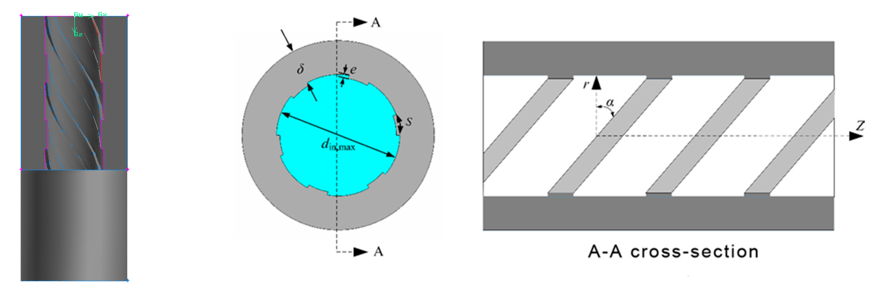
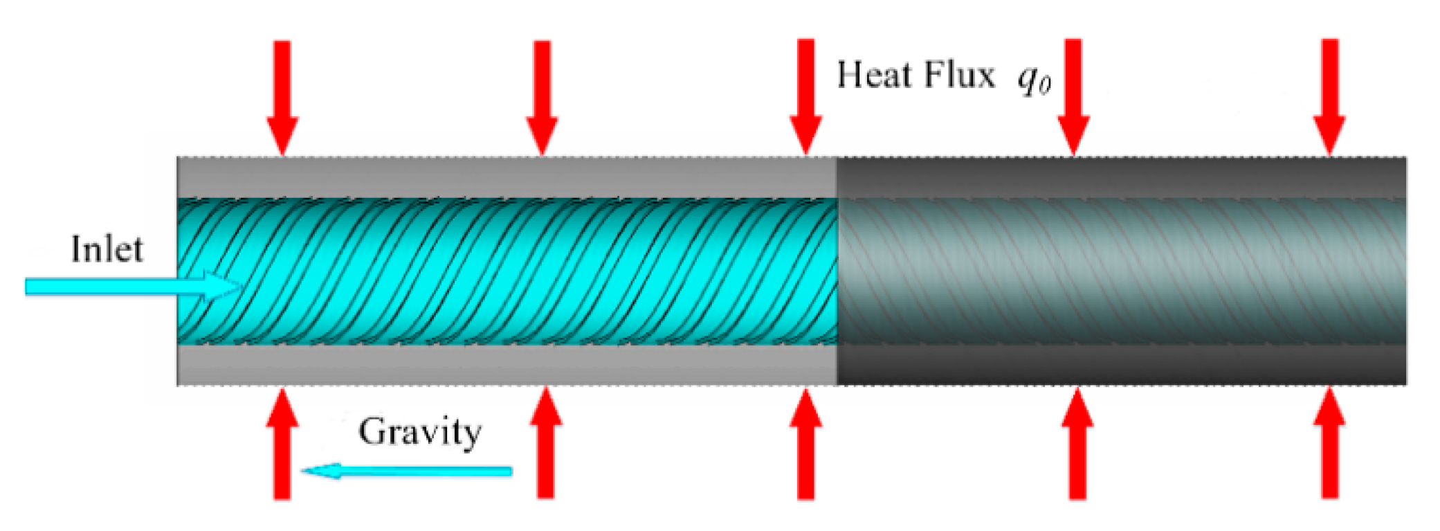
A three-dimensional physical model of IRT and its rib structure parameters are sketched in Figure 2, which made of SA-213T12 steel with an outer diameter (d0) of 33.40 mm and the maximum inner diameter (di,max) of 20.62 mm, the other fixed structural parameters of IRT used in the present studies are listed in Table 2. The heated length of the test section (L) is 2510 mm, with the heat flux from 120 kW/m2 to 250 kW/m2 added on the outer surface. In this model, thermophysical properties is assumed as the function of temperature but ignored the effect of pressure variation. The added heat flux is assumed to be uniformly distributed along the in the whole pipe circumference. The simulation is performed at the pressure of 25 MPa, the mass flux is 600 kg/(m2·s). The test section was installed vertically with an upward flow. Additionally, another smooth tube with OD/ID 33.40 /20.62 mm is selected as a reference.
2.2. Transport Equations
Transport equations for mass, momentum and energy were solved in the three-dimensional domain and can be described as follows:
where p is the static pressure, is the stress tensor (described below), and and are the gravitational body force and body forces.
To close the above equation group, Shear–stress Transport (SST) k–ω turbulent model [28] is applied in this paper, the turbulent kinetic energy k and the turbulent dissipation ω are employed to describe their turbulent characteristics. The turbulence transport equations were given by:
where
where Gk and Gω is the production of turbulence kinetic energy and specific dissipation rate, Yk and Yω represent the dissipation of turbulence kinetic energy and specific dissipation rate.
2.3. Numerical Method
In this study, the structured meshes with high qualities for our computational model are generated by ICEM software. As known from Ref [29,30,31], the mesh size near the wall greatly influence the simulation results. For accurate capturing the heat transfer characteristics of supercritical fluids, only if y+ ≤ 1, can get more reliable result. Therefore, 30 boundary layer grids are set in the near-wall region, and the size of the first layer grid is further adjusted according to the preliminary calculated y+ to make sure the final y+ within the range of 0.1~1. Besides, the heat conduction effect in the solid region have been also considered. The conjugated heat transfers between the solid domain and the fluid domain is solved. To maintain a reasonable gird number, a non-uniform structured grid size was adopted, where the same grid size is used in the transition region to match the interfaces at both sides of the inner wall. Additionally, the mesh independence solution is obtained by successively refining the original mesh. Finally, the total grid number in the whole calculated domain meshes is 9.85 million, and the mesh structure is shown in Figure 3.
Control volume method are applied and all equations should be solved by the ANSYS Fluent solver [28]. The SIMPLEC (Semi-Implicit Method for Pressure Linked Equations-Consistent) scheme was used for pressure–velocity coupling. The inlet is specified as the mass flux, the outlet in IRTs is set as the pressure outlet, the outer wall added a constant heat flux q0, no-slip wall condition is applied to the tube inner surface. The enhanced wall treatment model was adopted for the fluid cell near the wall, which can get more accurate results for supercritical fluids [29]. To get a better convergence, the convective term in momentum and energy equation are firstly solved with the first-order upwind scheme, and then the second-order upwind scheme is employed for solving transport equations after convergence.
2.4. Turbulence Model
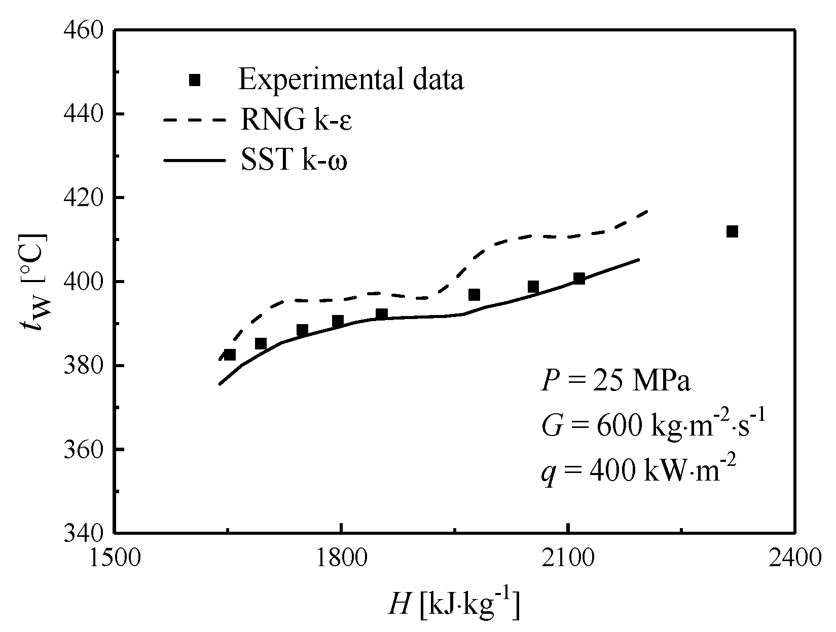
For modelling supercritical fluids, there is still no unified turbulence model due to its complexity turbulent heat transfer lead by steep variation in thermophysical properties. As checked in the previous research, the mostly common turbulence models for supercritical fluids are the RNG k-ε model with enhanced wall treatment [29] and the SST k-ω model [30]. To find out the best model for IRTs at supercritical pressures, both two turbulence models are employed to calculate their flow and heat transfer in the vertically upward IRT. Meanwhile, to verify the accuracy of the simulation model, the corresponding experimental data is also given. Figure 5 shows the calculated wall temperature obtained by numerical simulation and the experimental values of IRTs under a specified condition with mass flux of 600 kg/m2 s and heat flux of 400 kW/m2.
As seen in Figure 4, the wall temperature of IRT calculated by the RNG k-ε turbulence model is obviously higher than experimental results, especially in the vicinity of the pseudo-critical enthalpy (at P = 25 MPa, Hpc = 2152.9 kJ·kg−1). However, the wall temperature obtained by SST k-ω model agrees well with the experimental data [33]. Therefore, the SST k-ω turbulence model is used for analyzing the turbulent heat transfer in IRTs in the following works.
3. Results and Discussions
3.1. The Turbulent Heat Transfer of Supercritical Water in IRTs and STs
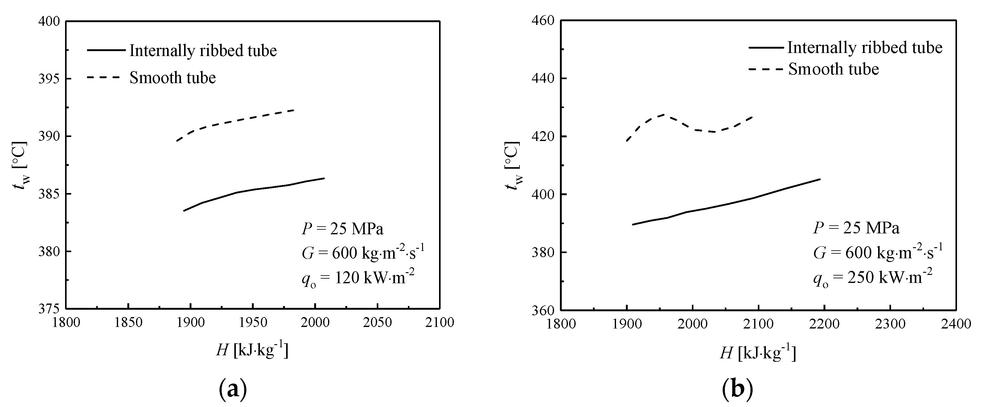
Compared to STs, IRTs can generally enhance the heat transfer to supercritical water, delay or avoid the HTD. To better understand the heat transfer difference between IRTs and STs, the inner-wall temperature of IRTs at different heat fluxes in the pseudocritical region has been firstly compared with that in STs, the results are shown in Figure 6. It should be pointed out that the inner-wall temperature of IRTs is non-uniformly distributed along the circumferential direction effected by the spiral rib structure, thus area-weight averaged temperature along the circumferential direction at each mesh node is calculated.
As shown in Figure 6a, at a low heat flux (i.e., q0 = 120 kW·m−2), the averaged inner-wall temperature of ST and IRT increases with the fluid bulk enthalpy, but the inner-wall temperature of IRT seem evidently lower than that in ST by 6~7 °C. When the heat flux increased to a higher value (i.e., q0 = 250 kW·m−2), as shown in Figure 6b, the corresponding averaged inner-wall temperature of ST rapidly rises as the increase of bulk enthalpy, and reaches the peak at H = 1950 kJ/kg, an obvious deteriorated heat transfer occurs in ST at this bulk enthalpy, then inner-wall temperature gradually decreases. However, the averaged inner-wall temperature of IRT varies smoothly without any peaks observed as the bulk enthalpy increases even under the condition with high heat fluxes. Thus, IRTs can enhance heat transfer and effectively avoid the occurrence of HTD.
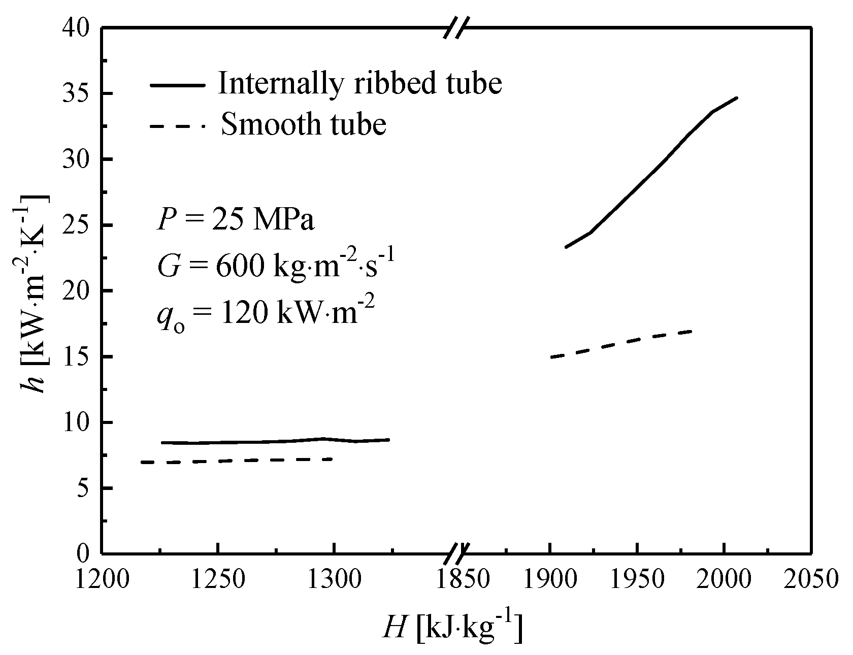
Figure 7 shows the comparison of the averaged heat transfer coefficient between IRT and ST at different enthalpy regions.
At low enthalpy region, the HTC of IRT is slightly higher than that of ST under the same enthalpies. However, when the bulk enthalpy enters into the pseudocritical region (about 1900–2300 kJ/kg), the difference of the averaged HTC between IRT and ST increases sharply, and the ratio IRT to ST is about 1.81, where the ratio is only 1.21 in the low-enthalpy region. Obviously, IRTs exhibits outstanding heat transfer capability in the pseudocritical region.
3.2. Distribution of Velocity Components in the Near-Wall Region
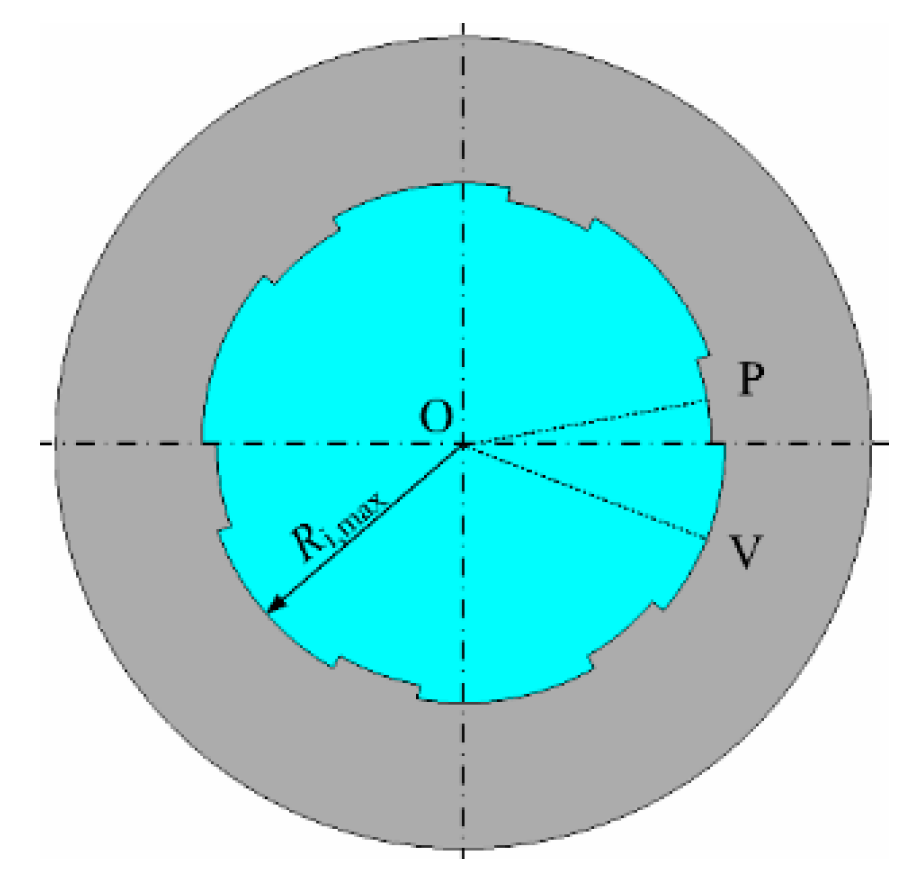
Within IRTs, an obvious spiral motion generated by spiral ribs/grooves in IRTs, which changes its distribution of velocity components, thermo-physical properties and turbulent heat transfer behaviors, and lead to different heat transfer regime. However, the influence of spiral ribs/grooves on the microfluidic structure of supercritical water in the near-wall region is limited until now. In this study, two distinctive cases were selected: (1) at low heat flux (q0 = 120 kW·m−2); (2) at high heat flux (q0 = 250 kW·m−2). Due to its differences in spiral ribs/grooves, the parameters at different radial positions corresponding to the grooves (the OV line) and the ribs (the OP line), as seen in Figure 8, are discussed, respectively. Meanwhile, the dimensionless distance (Y = 1 − r/Ri,max) are employed to describe the special heat transfer behaviors in both tubes, where r is the distance from the center of cross-section, and Ri,max represents the maximum inner radius of the tube. Additionally, according to the theory of boundary layer [31], three zones are divided in the boundary layer: if y+ < 5, the region is the viscous sublayer of turbulent flow; 5 < y+ < 70 is the transition region (or buffer layer); and y+ > 70 is the logarithmic layer (or turbulent core region).
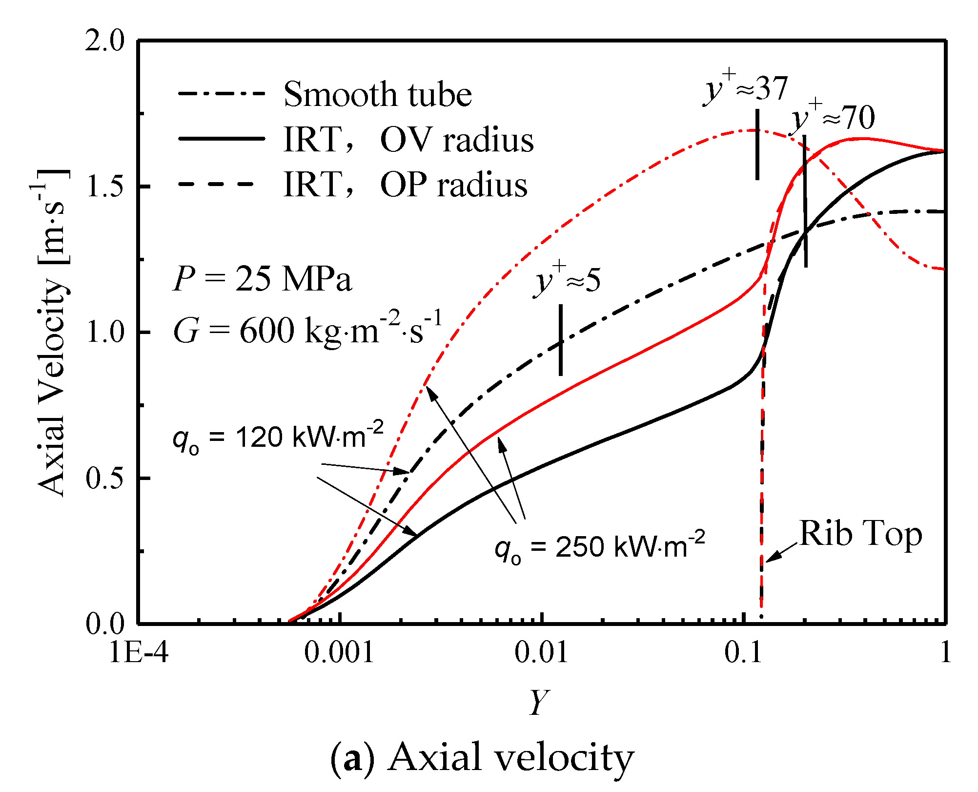
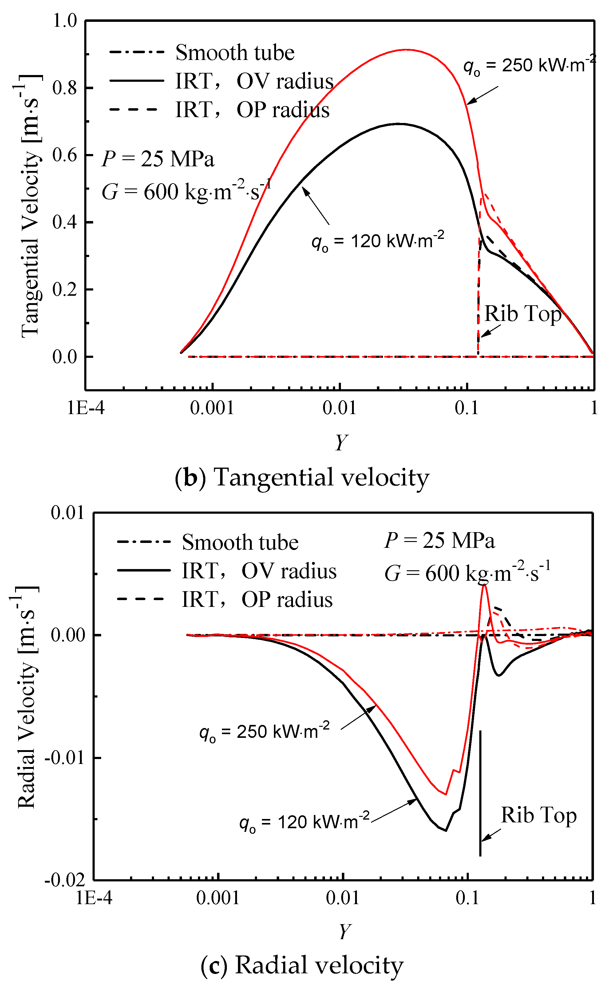
The axial velocity (a), tangential velocity (b) and radial velocity (c) components distribution of supercritical water in IRT and ST at H = 1950 kJ/kg are shown in Figure 9.
As shown in Figure 9a, comparing with the profile of axial velocity in IRT, the axial velocity in ST is relatively flat along the radial direction when the heat flux is 120 kW/m2. However, when the heat flux increases to 250 kW/m2, as seen in Figure 9b, the corresponding axial velocity varies and exhibits a distinct “M-shaped” distribution along the tube diameter direction in ST, where the maximum axial velocity appears at y+ ≈ 37 due to the deteriorated heat transfer occurs. However, no HTD observed in IRT at both heat fluxes, the axial velocity in the near-wall region is always lower than that in the center domain. For IRTs, the axial velocity of the supercritical water close to the top of rib is significantly higher than that near the groove due to the shrinkage of the cross-sectional size, thereby the convective heat transfer in the top of rib seems better. Moreover, the axial velocity in IRT is smaller than ST before y+ < 70, which is actually in the viscous sublayer and turbulent transition region. There is also no obvious thermal acceleration exists in the turbulent boundary layer, which means that thermal acceleration suppressed by the existence of the inner rib of the spiral, IRT can avoid (or slow down) the acceleration of the fluid in the boundary layer. As seen from Figure 9b, the tangential velocity of the supercritical water is close to zero because there is no spiral motion in ST, but the tangential velocity in IRT is remarkable and far beyond the corresponding value within ST. A peak of the tangential velocity appears in the groove region. The circumferential motion of the supercritical water in the cross-section of IRT exists but that does not exist in ST. Moreover, as the heat flux increases, the tangential velocity increases in IRT. As seen in Figure 9c, the radial velocity of the supercritical water in the cross-section of the ST is smaller than IRT. A significant radial motion generates in the cross-section of IRT, especially in the groove region, indicating that the fluid radial mixing is more intense in the cross section of IRT.
Known from the results of Figure 9, a spiral motion forms by the effect of the spiral internal rib, and induces a significant circumferential and radial movement in the cross section, especially in the groove region. The circumferential and radial movement are stronger, and intensify the fluid mixing in the cross section of IRT.
3.3. Distribution of Thermophysical Properties in the Near-Wall Region
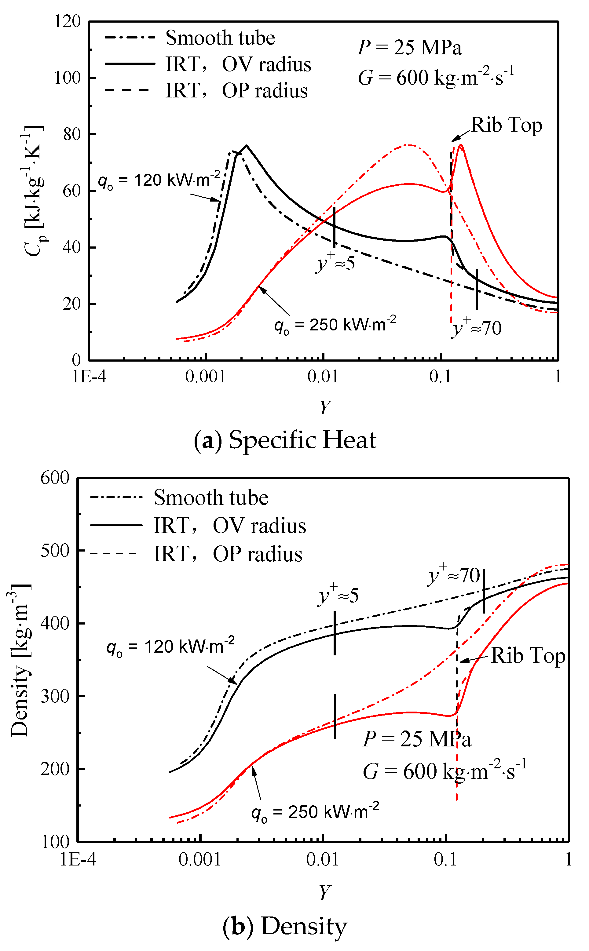
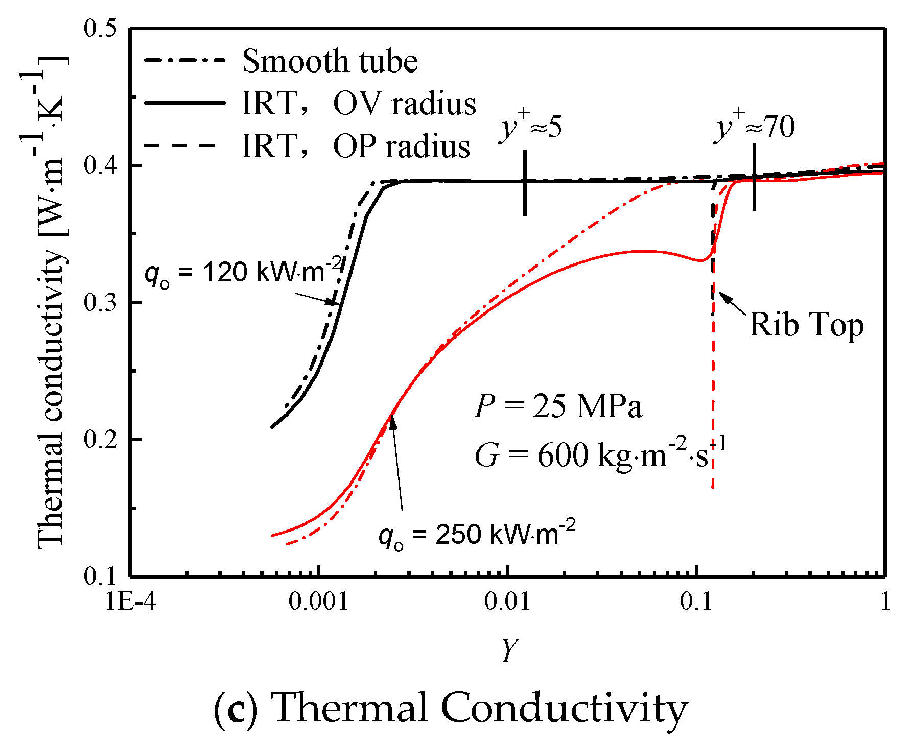
For supercritical fluids, the steep variation in pseudocritical region plays significant roles on turbulent heat transfer, thus the effect of thermophysical properties in the radial direction are also discussed, respectively. Figure 10 shows the comparison of the specific heat, density and thermal conductivity of supercritical water along the radial direction of IRT and ST at H = 1950 kJ/kg.
As seen in Figure 10a, for both IRT and ST, supercritical water with large specific heat located in the near-wall region at low heat flux, and the maximum specific heat are located within the viscous sublayer (y+ < 5), therefore, water can absorb a large amount of heat transferred from the wall to the fluid and enhances heat transfer. The specific heat of IRT is always greater than that of ST after reaches the peak value, which means that the heat transfer capacity in IRT is much stronger than that in ST. Once the heat flux achieved to a high value (q = 250 kW/m2), the occupied region with large specific heat increases significantly, and the corresponding specific heat peak moves to the transition region (5 < y+ < 70), but in the viscous sublayer (y+ < 5), the specific heat is significantly lower than that under the low heat flux, and the profile of specific heat in IRT is very close to ST. As at high heat fluxes, the bulk temperature near the wall rises rapidly and exceed the pseudo-critical temperature the heat transfer capacity in the turbulent viscous sublayer is weakened.
Similarly, as seen in Figure 10b,c, at low heat flux, the density and thermal conductivity of supercritical water in IRT is lower than the corresponding value in ST at the same Y. As the heat flux increases, the density and thermal conductivity of supercritical water is significantly reduced in IRT and ST. The density in ST is smaller than that in IRT at the position where the viscous sublayer is close to the wall (y+ < 5), but in the region of y+ > 5, the density and thermal conductivity in IRT is significantly lower than the corresponding value in ST. At low heat flux, the local inner temperature of the supercritical water in IRT is much higher than that in ST, resulting in a lower density in IRT. However, under high heat flux, the heat transfer deteriorates in ST because the heating wall is covered by a thin layer with high-temperature but low-density fluids, but for IRTs, heat transfer enhancement occurs, where the ribs make the fluid swirling and promote the heavy fluid migrate to the wall, and simultaneously restrict the light fluid (with low density and poor thermal conductivity) toward the center region.
3.4. Distribution of Turbulent Kinetic Energy within Boundary Layer
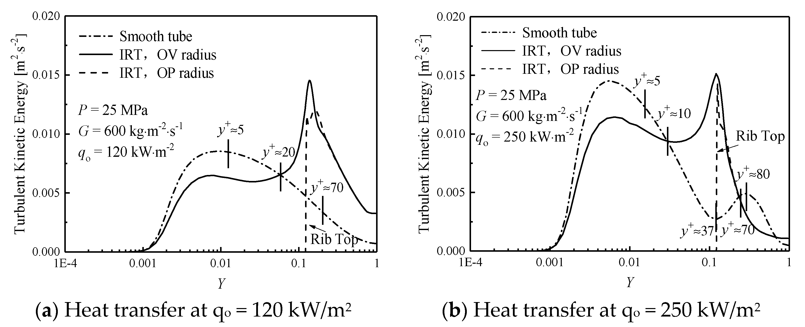
Figure 11 shows the comparison of the turbulent kinetic energy of supercritical water along the radial direction in IRT and ST.
As seen in Figure 11a, in smooth tube, the turbulent kinetic energy increases first and then decreases from the wall to the mainstream region, and a peak appeared in the viscous sublayer (y+ < 5). However, for IRTs, the variation of turbulent kinetic energy profile is complex. Under y+ < 20, the turbulent kinetic energy in IRT is lower than in ST, but in the transition region (5 < y+ < 70), especially in 20 < y+ < 70, the turbulent kinetic energy in IRT is significantly greater than that in ST, and the maximum value appears at the top of ribs. Interestingly, under high heat flux, as shown in Figure 11b, the turbulent kinetic energy on the cross-section of ST reaches a minimum value at y+ ≈ 37, and then recovers, another peak appears at y+ ≈ 80. Additionally, the turbulent kinetic energy of IRT reaches the maximum at the same location (y+ ≈ 37). Known from Figure 9, the corresponding axial velocity V reaches the maximum value in here, where the radial gradient (∂V/∂r) is sharply reduced, resulting in a sharp decrease of the turbulent shear stress. Such special variation of turbulence intensity in the transition region reflects that their heat transfer in such region plays an important role. For IRTs, due to the strong disturbance caused by the ribs, the radial velocity and turbulent kinetic energy in the corresponding position of IRT enhanced and reached the maximum value, so that the minimum value of the turbulent kinetic energy is successfully eliminated that is observed in ST under the condition of high heat flux, which enhances the heat transfer and effectively avoids the occurrence of HTD.
3.5. Effect of Rib Structure on Heat Transfer in IRTs
After discussing on the heat transfer mechanism in IRTs by comparing with their thermophysical properties and turbulent parameters distributions. The influence of rib structures (including lift angle, height, width and threads) on heat transfer are subsequently discussed, the corresponding variable rib structures have been shown in Table 2.
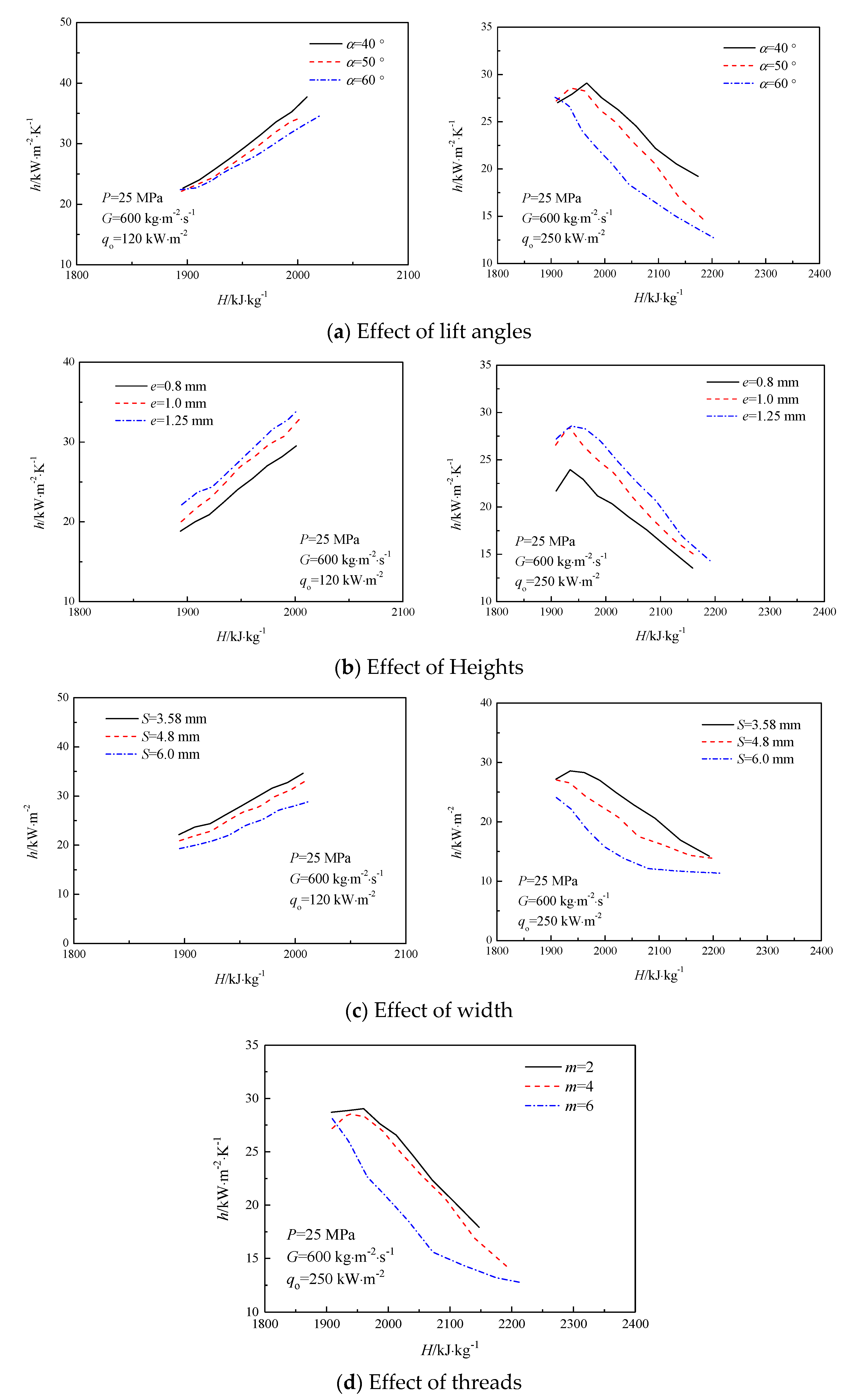
Figure 12. Effects of rib parameters on heat transfer of supercritical water is shown in Figure 11, the comparison of the heat transfer coefficient of the internally ribbed pipe with different rib parameters under the working conditions with pressure of 25 MPa, mass flow rate of 600 kg·m−2·s−1, and heat flux of 120 and 250 kW·m−2.
As seen in Figure 12a, with the rib lift angle increases, the averaged heat transfer coefficient in IRTs decreases. At low heat flux (qo =120 kW·m−2), when the rib lift angle increase from 40 to 60, the averaged HTC decreases at least 10%. However, at high heat flux, the heat transfer coefficient gradually decreases along with the bulk enthalpy. With the increase in lift angle, the corresponding heat transfer performance in IRT is weakened and the difference in heat transfer coefficient at various lift angle is even decreased by 80% on average. The higher the lift angle, the lower the HTC. As seen in Figure 12b, with the height of the rib increases, the averaged heat transfer coefficient increases because the disturbance of ribs enhances the heat transfer. When the rib height (e) increases from 0.8 mm to 1.25 mm, the averaged HTC increases 20% under these operating conditions. Evidently, the increase of the rib height is favorable for the heat transfer enhancement of the supercritical water in the internally ribbed tube. As the spiral ribs can deeply destory turbulent boundary layer, intensify the turbulent mixing under the effect of large height ribs. It can be seen from Figure 12c that as the circumferential rib width increases, the averaged heat transfer coefficient decreases, where the corresponding heat transfer of the supercritical water in IRTs is weakened as the increases of rib width. When the rib width decreases from 6.0 mm to 3.58 mm, the corresponding HTC increases 20% under these operating conditions. Moreover, as seen in Figure 12d, when the number of ribs (m) increases from 2 to 6, the averaged inner-wall temperature gradually increases 2 °C, but the corresponding HTC decreases 58% under these operating conditions. However, when the threads number is relatively small, such as m changes from 2 to 4, the heat transfer coefficient essentially unchanged, but if the threads number increases from 4 to 6, the heat transfer coefficient change remarkable. Such a situation can be explained by the following reasons. By increasing the threads number, the ratio between the groove width and rib width is reduced, causing the heat transfer in IRTs weakened.
3.6. Optimal Rib Structures in IRTs
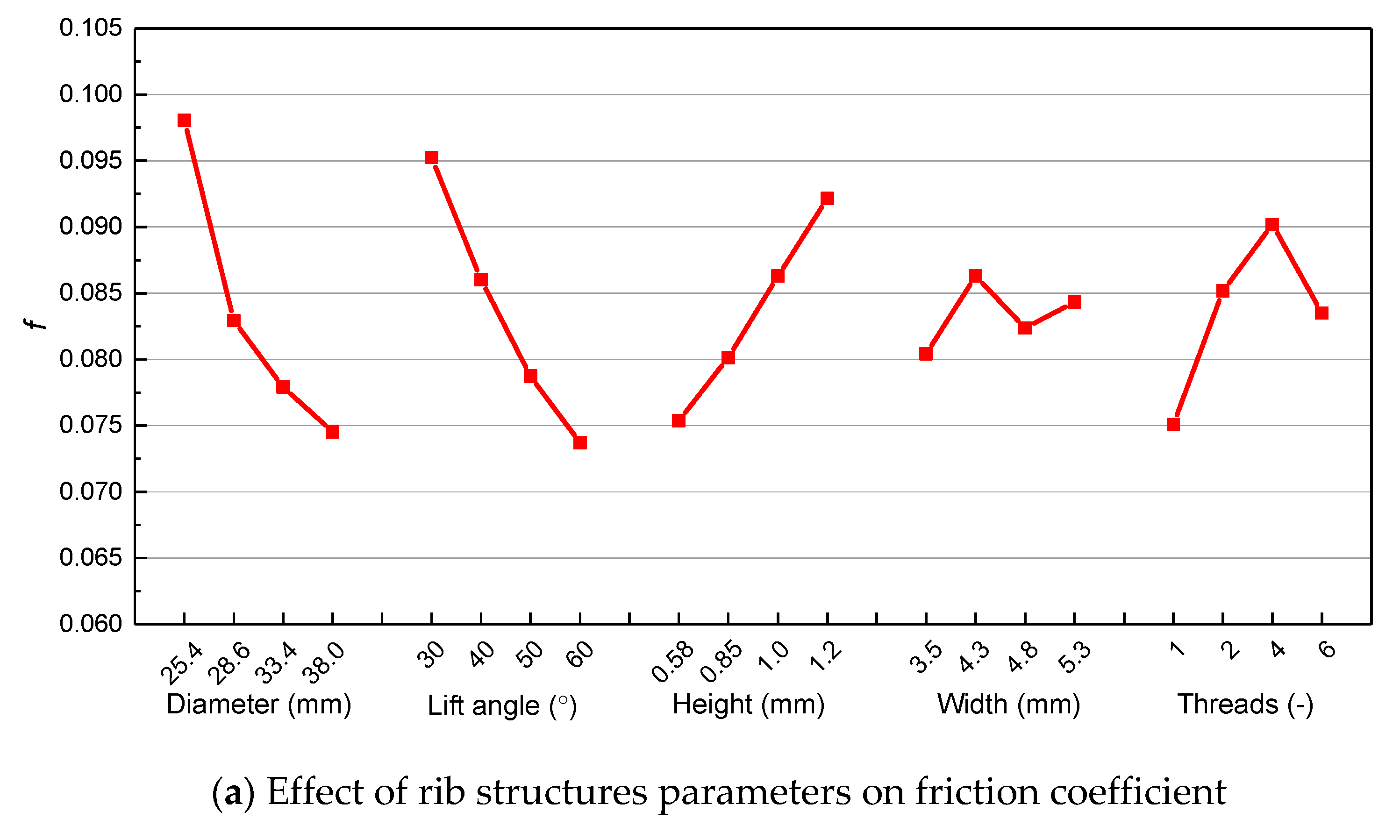
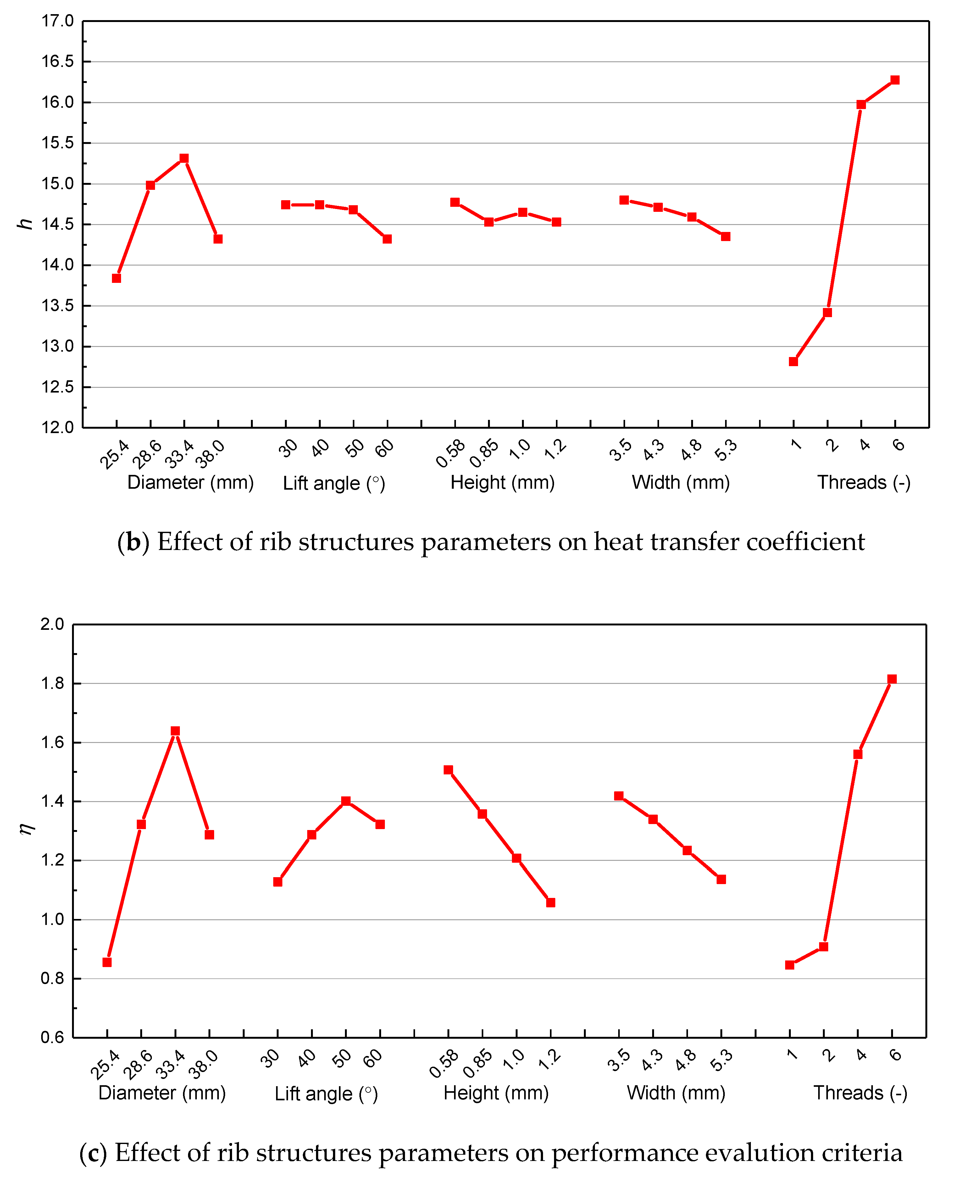
As mentioned above, ribs have a greatly effect on turbulent heat transfer of supercritical water, thus there is an optimal structure exists that can satisfy requirements of pressure drop and heat transfer. A series of further analysis on rib structures have been implemented according to the above discussions. The averaged frictional coefficient (a), heat transfer coefficient (b) and the dimensionless evaluating performance criteria (η) [34,35] for describing the ratio between frictional coefficient and heat transfer coefficient (c) at various rib structure parameters are shown in Figure 13.
As seen in Figure 13a, within our selected parameters range, it is found that the larger diameters and lift angles, the lower frictional coefficients. The smaller the rib height, the smaller frictional coefficient. Meanwhile, the effect of rib width and threads are not monotonic, when the width is 4.3 mm and threads number is 4, the frictional coefficient reached to the maximum. However, from the view of heat transfer coefficient, as shown in Figure 13b, the highest heat transfer coefficient appeared at different rib structures, as the lift angle, width increases, the corresponding heat transfer coefficients decreases, the threads number is monotonically varies with heat transfer coefficient. When the diameter is 33.4 mm, lift angle is 30 degrees, height is 0.58 mm, width is 3.5 mm, threads number is 6, the corresponding heat transfer coefficient will perform best. Moreover, another comprehensive dimensionless criteria () defined by the ratio between pressure drop and heat transfer has been employed, as shown in Figure 13c. When the diameter is 33.4 mm, lift angle is 50 degrees, height is 0.58 mm, width is 3.5 mm, threads number is 6, the corresponding heat transfer criteria will get the highest value, which means such rib structures in IRTs can get the best performance in the pseudocritical region, thus such optimal rib structures can be applied in heat exchanger. In practical engineering applications, we can also select different optimal rib structure that depends on our requirements. Table 3 summarized the best rib structure according to different. For example, when the resistance is the main consideration, it is better to select the rib parameter in the second row in Table 3.
4. Conclusions
In the present paper, the heat transfer characteristics of supercritical water in both IRTs and STs are comprehensively compared, and their thermophysical properties and turbulent kinetic energy distribution within the near-wall region in both pipes are analyzed and compared. Besides, the effects of the ribbed structural parameters on the heat transfer to supercritical water in IRTs were discussed, and then an optimal rib structure for IRTs have been obtained based on three different criteria. The main conclusions are as follows:
- IRTs can enhance the heat transfer to supercritical water as a result of the generation of obvious spiral flow, which produces significant circumferential and radial motion in the cross-section. At low heat fluxes, the temperature of IRT is lower than that in ST by 6~7 °C. At high heat fluxes, deteriorated heat transfer occurs in smooth tube, but not happens in IRTs, the maximum temperature difference is 36 °C. The heat transfer enhancement is more pronounced in the pseudocritical region, where the ratio between IRT and ST is about 1.81, but the ratio is only 1.21 in the low enthalpy region.
- In the cross-section, axial velocity suppressed, but tangential and radial velocity increases as a result of disturbance of spiral ribs, the velocity deviation between IRT and ST is about 20–50%. At low heat flux, the specific heat of supercritical water in IRT is about 3% greater than that of ST within the viscous sublayer (y+ < 5), resulting in a better heat transfer capability. However, at high heat flux, the heat transfer deteriorates occurs in ST because the heating wall is covered by a thin layer with high-temperature but low-density, low-thermal conductivity (a 20% reduction) fluids, but for IRTs, heat transfer enhancement occurs, where the ribs make the fluid swirling and promote the heavy fluid migrate to the wall, and simultaneously restrict the light fluid (with low density and poor thermal conductivity) toward the center region.
- In IRTs, a higher turbulent kinetic energy observed in the transition region of the turbulent boundary layer. At high heat flux, the turbulent kinetic energy in ST got a minimum value (=0.0025 m2⋅s−2) in the transition region of the turbulent boundary layer, and the axial velocity at this position reaches the maximum value (=1.7 m⋅s−1), which is a major cause to the occurrence of HTD. Due to the spiral flow induced by the internal rib, IRT can enhance the turbulent kinetic energy in the transition region and avoid the occurrence of the minimum value of the turbulent kinetic energy. IRT avoids (or postpones) the occurrence of HTD in supercritical water at high heat flux.
- With the increase in the lift angle of ribs, the HTC decreases; with the increase in the rib height, the HTC increases. As the circumferential rib width increases, the heat transfer coefficient decreases. When the threads number is relatively small (m ≤ 2), the heat transfer coefficient essentially unchanged, but if the threads number is high (m ≥ 4), the heat transfer coefficient change remarkable.
- An optimal rib structure has been obtained. When the diameter is 33.4 mm, lift angle is 50 degrees, height is 0.58 mm, width is 3.5 mm, threads number is 6, the corresponding overall performance is the best, which can be applied in engineering.
5. Further Scope
Internally ribbed heat transfer enhancement technology is wildly applied in many thermodynamic systems, which is also an promising technology in the new advanced thermodynamic system, such as 700 °C advanced ultra-supercritical (AUSC) coal-fired power generation technology, supercritical carbon dioxide (SCO2) Bryton power cycle.
To solve the surging demand in electricity, the increasingly prominent energy shortage and environmental pollution problems, it is an inevitable trend to develop 700 °C advanced ultra-supercritical (AUSC) coal-fired power generation technology based on currently supercritical power generation technology (Pressure: 35–37.5 MPa, Temperature: 700–760 °C). The design of heating surface in the boiler needs to satisfy an extremely high safety requirement, but IRTs is identified as an effecive way to manufacture the heating surface in the power plants. Additionally, the supercritical carbon dioxide (SCO2) Bryton power cycle has been considered as one of the promising energy conversion systems, which also faces extremely high temperture and heat transfer deterioration issue in future. Adapting an optimal rib structure internally ribbed tube can effectively enhance heat transfer and avoids (or postpones) the occurrence of HTD at high heat fluxes, which is potential to use in such advanced energy systems.
Author Contributions
Conceptualization, X.L. and H.L.; methodology, X.L.; validation, Z.G., R.P.; formal analysis, Z.G.; investigation, X.L.; writing—original draft preparation, X.L., Z.G.; writing—review and editing, R.P., H.L.; funding acquisition, X.L. All authors have read and agreed to the published version of the manuscript.
Funding
This research was funded by National Key Research and Development Project, grant number 2018YFB0604400.
Institutional Review Board Statement
Not applicable.
Informed Consent Statement
Not applicable.
Data Availability Statement
Data sharing not applicable.
Conflicts of Interest
The authors declare no conflict of interest.
Nomenclature
| Cp | specific heat at constant pressure, J/kg K |
| D | diameter, mm |
| e | height, mm |
| f | frictional coefficient |
| G | mass flux, kg/m2s |
| g | gravitational acceleration, m/s2 |
| H | enthalpy, kJ·kg−1 |
| h | heat transfer coefficient, kW·m−2·K−1 |
| k | turbulent kinetic energy, m2·s−2 |
| L | length, m |
| m | threads |
| Nu | Nusselt number |
| P | Pressure, MPa |
| p | pitch, mm |
| Pr | Prandtl number |
| q | heat flux, kW·m−2 |
| R | radius, mm |
| r | distance, mm |
| t | Time, s |
| Re | Reynolds number |
| S | width, mm |
| Greek Letters | |
| α | lift angel, ° |
| ΔP | pressure drop, kPa |
| β | thermal expansion coefficient, 1/°C |
| δ | thickness, mm |
| ε | turbulent dissipation rate, m2/s3 |
| η | Performance |
| λ | Thermal conductivity, W·m−1·K−1 |
| μ | dynamic viscosity, Pa s |
| μt | turbulent eddy viscosity, Pa s |
| k | turbulent kinetic energy, kg⋅m/s2 |
| ρ | density, kg/m3 |
| ω | Specific dissipation, 1/s |
| Y | Non-Dimensional Distance; (1-r/Ri,max) |
| Subscripts or superscripts | |
| b | bulk |
| i, j, k | i, j, k components |
| pc | pseudocritical |
| t | turbulent |
References
- Swenson, H.S.; Carver, J.R.; Szoeke, G. The effects of nucleate boiling versus film boiling on heat transfer in power boiler tubes. J. Eng. Power 1962, 84, 365–371. [Google Scholar] [CrossRef]
- Ackerman, J.W. Pseudoboiling heat transfer to supercritical pressure water in smooth and ribbed tubes. J. Heat Transf. Trans. ASME 1970, 92, 490–497. [Google Scholar] [CrossRef]
- Watson, G.; Lee, R. Critical heat flux in inclined and vertical smooth and ribbed tubes. In Proceedings of the 5th International Heat Transfer Conference, Tokyo, Japan, 3–7 September 1974; pp. 275–279. [Google Scholar]
- Griem, H. A new procedure for the prediction of forced convection heat transfer at near- and supercritical pressure. Heat Mass Transf. 1996, 31, 301–305. [Google Scholar] [CrossRef]
- Köhler, W.; Kastner, W. Heat transfer and pressure loss in rifled tubes. In Proceedings of the 8th International Heat Transfer Conference, San Francisco, CA, USA, 17–22 August 1986; pp. 2861–2865. [Google Scholar]
- Cheng, L.X.; Chen, T.K. Study of vapor liquid two-phase frictional pressure drop in a vertical heated spirally internally ribbed tube. Chem. Eng. Sci. 2007, 62, 783–792. [Google Scholar] [CrossRef]
- Cheng, L.X.; Chen, T.K. Study of single phase flow heat transfer and friction pressure drop in a spiral internally ribbed tube. Chem. Eng. Technol. 2006, 29, 588–595. [Google Scholar] [CrossRef]
- Cheng, L.X.; Chen, T.K. Enhanced heat transfer characteristics of upward flow boiling of kerosene in a vertical spirally internally ribbed tube. Chem. Eng. Technol. 2006, 29, 1233–1241. [Google Scholar] [CrossRef]
- Cheng, L.X.; Xia, G. Experimental study of CHF in a vertical spirally internally ribbed tube under the condition of high pressures. Int. J. Therm. Sci. 2002, 41, 396–400. [Google Scholar] [CrossRef]
- Cheng, L.X.; Chen, T.K. Flow boiling heat transfer in a vertical spirally internally ribbed tube. Heat Mass Transf. 2001, 37, 229–236. [Google Scholar] [CrossRef]
- Wang, J.G.; Li, H.X.; Guo, B.; Yu, S.Q. Heat transfer of water at supercritical pressures in vertically-upward internally-ribbed tubes. J. Eng. Thermophys. 2009, 30, 423–427. [Google Scholar]
- Wang, J.; Li, H.; Yu, S.; Chen, T. Investigation on the characteristics and mechanisms of unusual heat transfer of supercritical pressure water in vertically-upward tubes. Int. J. Heat Mass Transf. 2011, 54, 1950–1958. [Google Scholar] [CrossRef]
- Wang, J.; Li, H.; Yu, S.; Chen, T. Comparison of the heat transfer characteristics of supercritical pressure water to that of subcritical pressure water in vertically-upward tubes. Int. J. Multiph. Flow 2011, 37, 769–776. [Google Scholar] [CrossRef]
- Wang, J.; Li, H.; Guo, B.; Yu, S.; Zhang, Y.; Chen, T. Investigation of forced convection heat transfer of supercritical pressure water in a vertically upward internally ribbed tube. Nucl. Eng. Des. 2009, 239, 1956–1964. [Google Scholar] [CrossRef]
- Pan, J.; Yang, D.; Dong, Z.; Zhu, T.; Bi, Q. Experimental investigation on heat transfer characteristics of low mass flux rifled tube with upward flow. Int. J. Heat Mass Transf. 2011, 54, 2952–2961. [Google Scholar] [CrossRef]
- Yang, D.; Pan, J.; Zhou, C.Q.; Zhu, X.; Bi, Q.; Chen, T. Experimental investigation on heat transfer and frictional characteristics of vertical upward rifled tube in supercritical CFB boiler. Exp. Therm. Fluid Sci. 2011, 35, 291–300. [Google Scholar] [CrossRef]
- Taklifi, A.; Hanafizadeh, P.; Behabadi, M.A.; Aliabadi, A. Experimental investigation on heat transfer and pressure drop of supercritical water flows in an inclined rifled tube. J. Supercrit. Fluids 2016, 107, 209–218. [Google Scholar] [CrossRef]
- Shen, Z.; Yang, D.; Mao, K.; Long, J.; Wang, S. Heat transfer characteristics of water flowing in a vertical upward rifled tube with low mass flux. Exp. Therm. Fluid Sci. 2016, 70, 341–353. [Google Scholar] [CrossRef]
- Zhao, Z.X.; Wang, X.Y.; Che, D.F. Numerical study on heat transfer and resistance characteristics of supercritical water inside internally-ribbed tube. Heat Mass Transf. 2014, 50, 559–572. [Google Scholar] [CrossRef]
- Xu, W.; Wang, W.; Du, X.; Zhu, X. Numerical investigation on the secondary flow of supercritical water in a four-head internally ribbed tube. Appl. Therm. Eng. 2017, 120, 708–718. [Google Scholar] [CrossRef]
- Nishikawa, K.; Fujii, T.; Yoshida, S. Flow boiling crisis in grooved boiler-tubes. In Proceedings of the 5th International Heat Transfer Conference, Tokyo, Japan, 3–7 September 1974; pp. 270–274. [Google Scholar]
- Kim, C.H.; Bang, I.C.; Chang, S.H. Critical heat flux performance for flow boiling of R-134a in vertical uniformly heated smooth tube and rifled tubes. Int. J. Heat Mass Transf. 2005, 48, 2868–2877. [Google Scholar] [CrossRef]
- Hawig, A.A. CFD Study on the Heat Transfer in Vertical Rifled Tube with Different Helical Angles; Tun Hussein Onn University of Malaysia: Johor, Malaysia, 2010. [Google Scholar]
- Koshad, R.A.S. CFD Simulation of Heat Transfer in Vertical Ribbed Tube; Tun Hussein Onn University of Malaysia: Johor, Malaysia, 2011. [Google Scholar]
- Lam, S.P. Analysis of the Flow Characteristic Inside a Heated and Unheated Horizontal Rifled Tube; Tun Hussein Onn University of Malaysia: Johor, Malaysia, 2012. [Google Scholar]
- Li, Z.; Lu, J.; Tang, G.; Liu, Q.; Wu, Y. Effects of rib geometries and property variations on heat transfer to supercritical water in internally ribbed tubes. Appl. Therm. Eng. 2015, 78, 303–314. [Google Scholar] [CrossRef]
- Li, Z.; Wu, Y.; Tang, G.; Zhang, D.; Lu, J. Comparison between heat transfer to supercritical water in a smooth tube and in an internally ribbed tube. Int. J. Heat Mass Transf. 2015, 84, 529–541. [Google Scholar] [CrossRef]
- ANSYS Inc. ANSYS Fluent User’s Guide; ANSYS Inc.: Canonsburg, PA, USA, 2013. [Google Scholar]
- Roelofs, F. CFD Analyses of Heat Transfer to Supercritical Water Flowing Vertically Upward in a Tube; Jahrestagung Kerntechnik: Nuremberg, Germany, 2004. [Google Scholar]
- Liu, L.; Xiao, Z.; Yan, X.; Zeng, X.; Huang, Y. Heat transfer deterioration to supercritical water in circular tube and annular channel. Nucl. Eng. Des. 2013, 255, 97–104. [Google Scholar] [CrossRef]
- Mirkhani, N.; Taklifi, A.; Hanafizadeh, P.; Aliabadi, A. Numerical Study on the Hydraulic and Thermal Performance of Internally Ribbed Tubes in Supercritical Pressure and Subcritical Two-phase Flows. J. Supercrit. Fluids 2018, 136, 21–28. [Google Scholar] [CrossRef]
- Lemmon, E.W.; Huber, M.L.; McLinden, M.O. NIST Reference Fluid Thermodynamic and Transport Properties—REFPROP; U.S. Department of Commerce Technology Administration: Gaithersburg, MD, USA, 2013.
- Zhang, Q.; Li, H.; Zhang, W.; Li, L.; Lei, X. Experimental study on heat transfer to the supercritical water upward flow in a vertical tube with internal helical ribs. Int. J. Heat Mass Transf. 2015, 89, 1044–1053. [Google Scholar] [CrossRef]
- Córcoles, J.I.; Moya-Rico, J.D.; Molina, A.E.; Almendros-Ibáñez, J.A. Numerical and experimental study of the heat transfer process in a double pipe heat exchanger with inner corrugated tubes. Int. J. Therm. Sci. 2020, 158, 106526. [Google Scholar] [CrossRef]
- Wang, W.; Zhang, Y.; Lee, K.S.; Li, B. Optimal design of a double pipe heat exchanger based on the outward helically corrugated tube. Int. J. Heat Mass Transf. 2019, 135, 706–716. [Google Scholar] [CrossRef]
Figure 1.
Schematic of internally ribbed tube (IRT) and its Structural Parameters in the Cross-section (where e is the rib height, S is the rib width, α is the rib lift angle, and α is defined as the angle between the spiral direction of the rib and the cross section of the pipe. Under the same pipe diameter, the larger the lift-angle of the thread, the larger the rib pitch).

Figure 2.
Schematic of the physical model and structure.

Figure 3.
Mesh of IRTs and local mesh in the near-wall region.

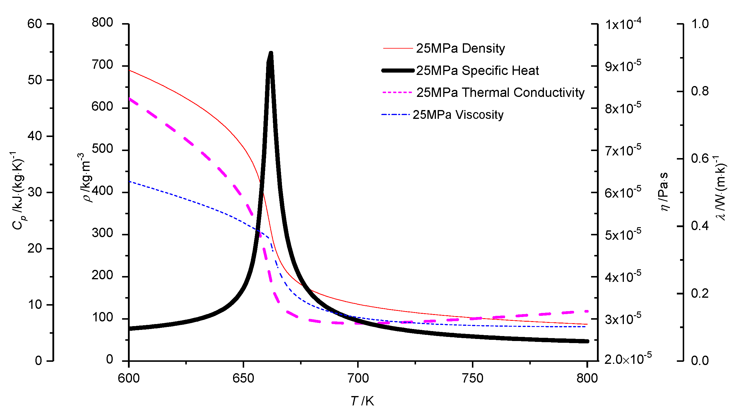
Figure 4.
Variation of themophysical properties at P = 25 MPa.

Figure 5.
Turbulence model verification results (exp. Data from [33]).
Figure 5.
Turbulence model verification results (exp. Data from [33]).

Figure 6.
The inner-wall temperature in pseudocritical region. (a) Heat transfer enhancement; (b) Heat transfer deterioration.
Figure 6.
The inner-wall temperature in pseudocritical region. (a) Heat transfer enhancement; (b) Heat transfer deterioration.

Figure 7.
Variation of heat transfer coefficient (HTC) in different enthalpy regions.

Figure 8.
Radius diagram of the rib top and groove.

Figure 9.
Comparison of velocity components distribution of supercritical water in IRT and ST.


Figure 10.
Comparison of the thermophysical properties distribution of supercritical water in IRT and ST.
Figure 10.
Comparison of the thermophysical properties distribution of supercritical water in IRT and ST.


Figure 11.
Comparison of radial distribution of turbulent kinetic energy.

Figure 12.
Effects of rib parameters on heat transfer of supercritical water.

Figure 13.
Effect of rib structures parameters on flow and heat transfer.


Table 1.
Summary of the rib structures of IRTs in the open literature.
| Author | m | p/mm | e/mm | S/mm | α/° | D/mm |
|---|---|---|---|---|---|---|
| Ackerman [2] | 6 | 21.84 | — | — | — | 18.03 |
| Griem [4] | — | — | — | — | — | 24 |
| Cheng [6,7] | 4 | 10.04 | 0.58 | 4.61 | 49.3 | 11.69 |
| Cheng [8,9,10] | 4 | 21 | 0.81 | 4.8 | 61.15 | 15.24 |
| Wang [11,12,13] | 4 | 21.55 | 0.85 | 4.8 | 60 | 15.24 |
| Wang [14] | 6 | 11.61 | 1.20 | 4.8 | 50 | 17.63 |
| Pan [15] | 4 | 19 | 0.92 | 4.62 | 50.5 | 19.4 |
| Yang [16] | 4 | 22.7 | 0.85 | 5.3 | 54 | 20.3 |
| Taklifi [17] | 6 | 10.8 | 1.2 | 4.77 | 45 | 19 |
| Shen [18] | 4 | 18.1 | 1.24 | 6.2 | 50 | 19.1 |
Table 2.
The rib structural parameters of specific IRT.
| Structural Parameters | Fixed Rib Structure | Variable Rib Structures |
|---|---|---|
| Outside diameter (d0) | 33.40 mm | 25.4, 28.6, 33.4, 38 mm |
| Maximum inside diameter (di,max) | 20.62 mm | 20.62 mm |
| Length (L) | 2510 mm | 2510 mm |
| Number of threads (m) | 6 | 1, 2, 4, 6 |
| Rib width (S) | 3.58 mm | 3.5, 4.3, 4.8, 6.0 mm |
| Rib height (e) | 0.8 mm | 0.58, 0.85, 1.0, 1.2 mm |
| Rib lift angle (α) | 30° | 30, 40, 50, 60° |
| Pitch (p) | 12.87 mm | 12.87 mm |
| Lead (m × p) | 77.2 mm | 51.48, 77.22, 102.96 mm |
Table 3.
The best rib structure at different performance evaluating criteria.
| Criteria | Diameter (mm) | Lift Angle (°) | Height (mm) | Width (mm) | Threads (-) |
|---|---|---|---|---|---|
| h | 33.4 | 30 | 0.58 | 3.5 | 6 |
| f | 38 | 60 | 0.58 | 3.5 | 1 |
| η | 33.4 | 50 | 0.58 | 3.5 | 6 |
Publisher’s Note: MDPI stays neutral with regard to jurisdictional claims in published maps and institutional affiliations. |
© 2021 by the authors. Licensee MDPI, Basel, Switzerland. This article is an open access article distributed under the terms and conditions of the Creative Commons Attribution (CC BY) license (http://creativecommons.org/licenses/by/4.0/).
Share and Cite
MDPI and ACS Style
Lei, X.; Guo, Z.; Peng, R.; Li, H. Numerical Analysis on the Heat Transfer Characteristics of Supercritical Water in Vertically Upward Internally Ribbed Tubes. Water 2021, 13, 621. https://doi.org/10.3390/w13050621
AMA Style
Lei X, Guo Z, Peng R, Li H. Numerical Analysis on the Heat Transfer Characteristics of Supercritical Water in Vertically Upward Internally Ribbed Tubes. Water. 2021; 13(5):621. https://doi.org/10.3390/w13050621
Chicago/Turabian StyleLei, Xianliang, Ziman Guo, Ruifeng Peng, and Huixiong Li. 2021. "Numerical Analysis on the Heat Transfer Characteristics of Supercritical Water in Vertically Upward Internally Ribbed Tubes" Water 13, no. 5: 621. https://doi.org/10.3390/w13050621
Note that from the first issue of 2016, this journal uses article numbers instead of page numbers. See further details here.