
Laboratory Tests of New Groundwater Table Level Regulators in Subsurface Drainage Systems


1
Institute of Environmental Engineering, Warsaw University of Life Sciences SGGW, PL 00-090 Warsaw, Poland
2
Institute of Civil Engineering, Warsaw University of Life Sciences SGGW, PL 00-090 Warsaw, Poland
*
Author to whom correspondence should be addressed.
Water 2021, 13(5), 631; https://doi.org/10.3390/w13050631
Submission received: 7 January 2021
/
Revised: 12 February 2021
/
Accepted: 25 February 2021
/
Published: 27 February 2021
(This article belongs to the Special Issue Design, Management and Environmental Control of Modernized Irrigation Systems)
Abstract
:The changes in hydrological conditions observed nowadays require economical use of water. This applies to water management both on a national scale and river basins and catchments, as well as on the scale of drainage systems and individual drainage networks. Outflow regulation is carried out by extending the outflow time of surface water collected during rainfall in various forms of retention in the catchment area. One of the devices for regulating the outflow of groundwater is a drainage network, traditionally used as a drainage system. The water level regulators presented in this article enable the damming of water in the drainage network, in pipelines and in the adjacent ground. The conducted tests were aimed at determining the hydraulic characteristics and operating conditions of two innovative solutions of water level regulators in drainage systems. These regulators are characterised by the possibility of smooth regulation by the use of rotary or propeller systems for smoothly setting the damming level. Both tested regulators are characterised by the presence of an effective flow, the value of which was set at the level of Qe = 0.17 l·s−1 to Qe = 0.25 l·s−1 for the funnel regulator and Qe = 0.009 l·s−1 to Qe = 0.015 l·s−1 for a hole regulator. Laboratory tests of the prototypes showed that the funnel regulator allows one to maintain the damming level in a flow rate range of up to 5.5 l·s−1, with possible damming up to 3 cm, regardless of the height of the shaft. The hole regulator is characterised by a flow control range of up to Q = 0.65 l·s−1, greater variability of the damming levels and the need to change the position of the working openings, depending on the flow rate.
1. Introduction
The condition of water resources in Poland, one of the lowest among European countries, results mainly from climatic and physiographic conditions. The average rainfall for Poland is about 600 mm, but in the middle part of country, it drops to about 450 mm, thus reaching a height equivalent to water losses on field evaporation and plant transpiration.
The increasingly pronounced changes in the climate, as well as the progressive anthropopression, will reduce water resources. This is indicated by the results of research carried out in Poland on the observed and forecasted climate changes. On the basis of data in the period of 1961–2017 from 60 weather stations, a significant increase in the average air temperature by 1.7 °C was found [1]. A clear periodical tendency of changes in the amount of precipitation in the summer and winter half-year was found in the period of 1991–2015 as compared to the period of 1961–1990 [2,3]. The greatest decrease in rainfall by 10–25% occurred in the central part of Poland.
The increasing water deficit in central Poland in recent years has resulted in an intensification of the phenomenon of atmospheric drought and, consequently, agricultural drought. The agricultural drought in 2015 was particularly severe, as it covered 2 million ha of arable land, while in 2019, it covered 1.8 million ha. According to the forecasts of the UN Intergovernmental Panel on Climate Change [4], the frequency of 100 years droughts, i.e., those occurring in the previous climate once every 100 years, will increase at least 10 times, which means that catastrophic droughts will affect Poland more often than every 10 years. Preparing Polish agriculture for the upcoming changes is therefore a very necessary and urgent task.
The State Water Holding Polish Waters (in 2016–2020) developed plans to counteract the effects of drought (PPSS) in the river basin areas [5]. As part of the analytical work, it was found, inter alia, that extreme risk of agricultural drought occurs in about 45% of the agricultural and forest area of Poland. The aim of the PPSS is primarily to increase water retention (in the form of ground, habitat and reservoir retention) and to improve water distribution by controlling and regulating the outflow [6,7,8,9,10].
In crops, water collection and control of its outflow are carried out in both open drainage systems (ditches) [11,12] and closed drainage systems [13,14,15]. Vortex and shaft regulators [16,17,18,19,20] are used to regulate the flow in watercourses [21] and in reservoirs [22,23,24,25,26]. A large group are float regulators to regulate the upper or lower water level [27]. One of the methods of increasing water retention in water drainage facilities is the use of water-damming regulators in the drainage network [28,29,30,31]. These devices, installed in drainage wells, slow down the outflow from the facility by damming the groundwater at a given height – higher than the elevation of the drain position. Regulators’ actions periodically transform the drainage system into a subsoil irrigation system. For this reason, the use of water-damming regulators in the drainage network has become one of the goals of the INOMEL project—“Technological Innovation and a System for Monitoring, Forecasting and Operational Planning of Drainage Activities for Precise Water Management on the Scale of a Drainage Facility” (BIOSTRATEG3/347837/11/NCBR/2017). As part of the project, research teams from the Department of Water Engineering and Management, Institute of Technology and Life Sciences in Falenty [32], and from the Faculty of Environmental Engineering and Spatial Management, Poznań University of Life Sciences [33], developed the design and technological assumptions of water-damming regulators in the drainage network. Prototypes of the new devices were made by S. i A. Pietrucha Sp. z o.o., while the tests and validation of the devices in laboratory conditions were carried out at the Hydraulic Laboratory of the Warsaw University of Life Sciences.
The exploratory research described in the article was on a pilot scale. We tested two prototypes of regulators. Innovative solutions were applied, with a design that is little known and has not been studied in this application so far. The prototypes of the regulators were made so that in practice they could cooperate with devices currently used in subsurface drainage systems. Their parameters were dictated by the technical requirements of devices such as drainage chambers and drainage. The priority goal was to develop the concept of controllers with a simple design using available cheap plastic materials (components).
2. Materials and Methods
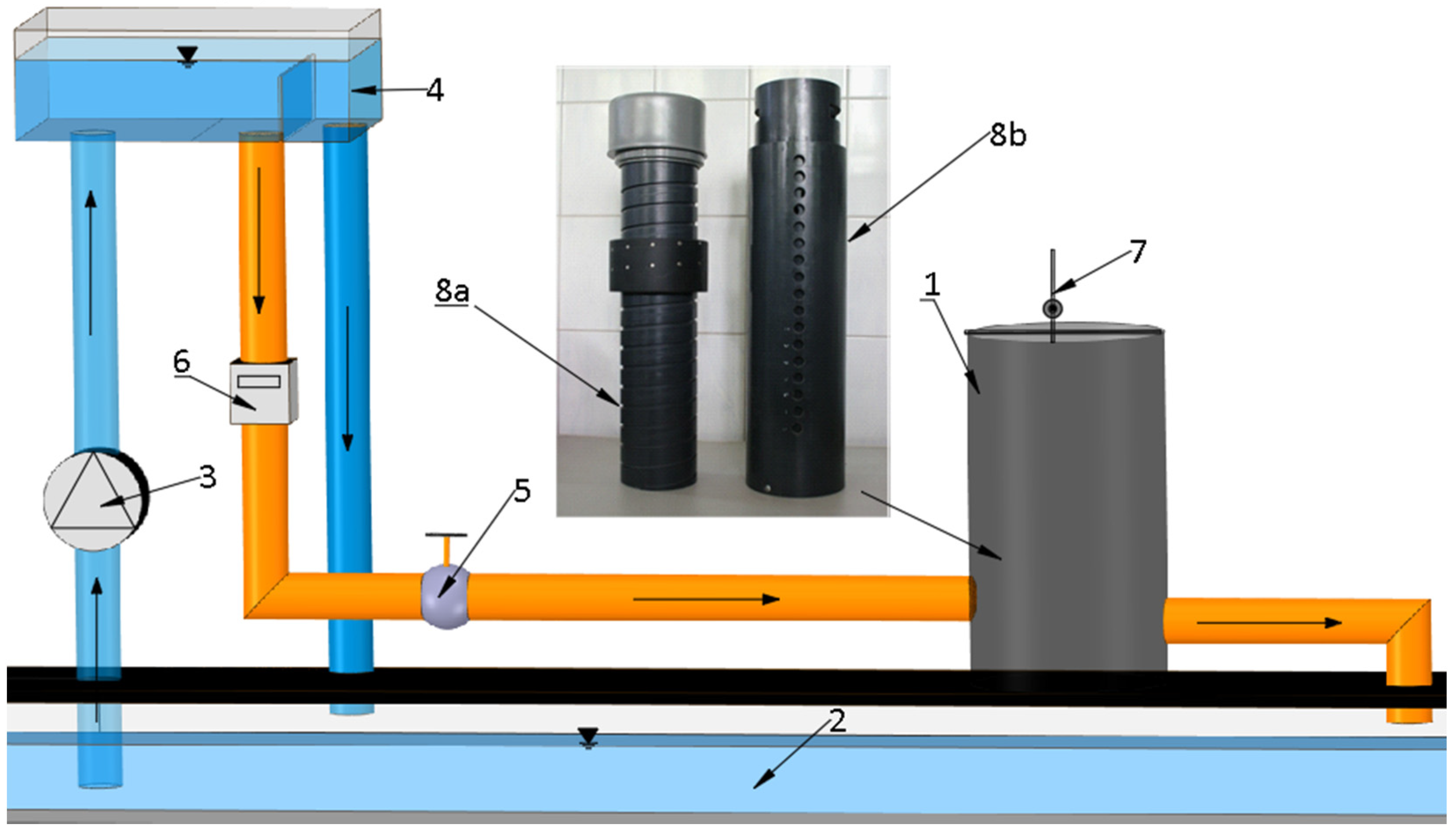
The test stand (Figure 1) was supplied with water in a closed-circuit system, which included a down tank, a pump, an upper stability tank, a regulating valve and an electromagnetic flow meter. A stream of water with flow rate Q l·s−1 flowed through the tested regulator. Flow rate measurement had an accuracy of ±1%. Precise water gauge staffs with a reading accuracy of ±1 × 10⁻⁴ m (±0.01 cm) were used to measure the water levels. Laboratory tests of rotary regulators were carried out in a plastic pit with an internal diameter of 95 cm and a height of 120 cm, with inlet and outlet drains with a diameter of 20 cm (Figure 2 and Figure 3). The aim of the laboratory tests was to evaluate the design and functioning of the regulators under conditions of variable hydrostatic and hydrodynamic loads, in terms of their tightness, deformation and flow, as well as the methods of installation and operation. The subject of the research were two prototype rotary regulators of water damming in the drains, a funnel regulator (Figure 2) and a hole regulator (Figure 3). The tested regulators were prototype patent solutions. They were made on a 1:1 scale; therefore, the principles of modelling criteria were not used and the parameters were not recalculated. Both regulators are designed to be mounted in drainage wells using a typical PVC tee with a diameter of 150 mm. The regulators installed in pipes with dirty water included a flap installed optionally in the drain plug (4 in Figure 2 and Figure 3). Laboratory tests were performed with clean water without sediment and suspensions.
The best use of the laboratory tests is in determining the characteristics of the regulators for the full range of level and flow regulation. It is difficult to obtain such a wide range of measuring depths and flows on a real object in a drainage plot, with simultaneous observation of flow forms for conditions in a natural object. The proposed regulators were developed in relation to the typical structures of drainage wells and the diameters of the main drains collecting and draining water from the drainage plots. This allowed for the mapping of the actual conditions in drainage systems and the direct use of the results obtained in practice.
2.1. The Funnel Regulator
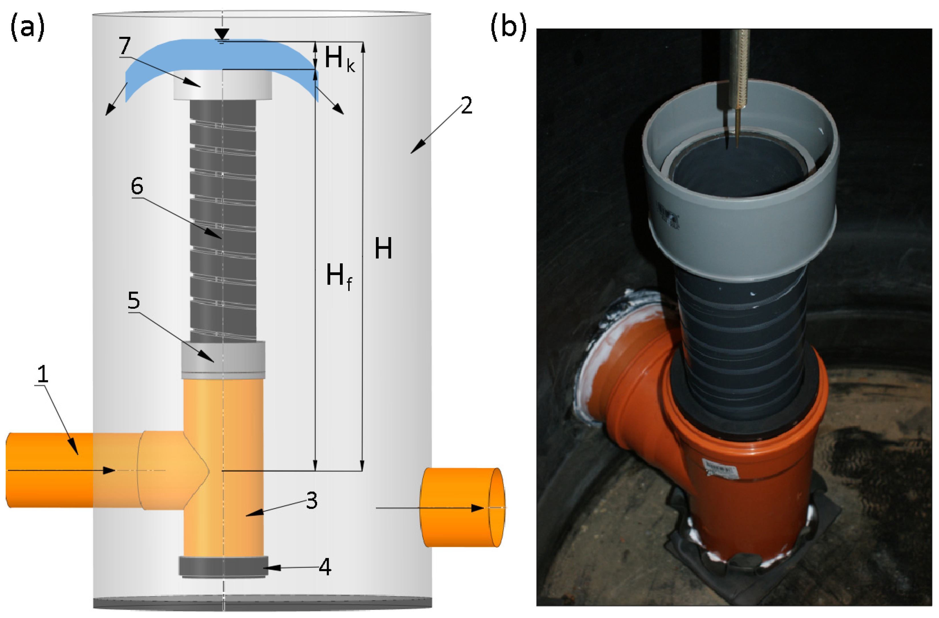
The funnel regulator (Figure 1: 8a, Figure 2) is made of a stem pipe (6 in Figure 2) with a diameter of 125 mm, having a long-pitch fluted thread. The use of the thread enables smooth rotation of the pipe with the funnel (7 in Figure 2) mounted on its upper end in relation to the stabilising ring-shaped base (5 in Figure 2), which is fixed in the tee (3 in Figure 2) with the use of a gasket. To set the required height of the funnel overflow edge position (7 in Figure 2) above the drain axis, Hf (Figure 2), the pipe is screwed in/wrung out from the base. The test specimen, 63 cm long, enables the position of the crown of the funnel overflow in relation to the drain axis within the height range of Hf = 47–75 cm. In the flare regulator, the water flowing from the drain (1 in Figure 2) initially collects in the vertical base (5 in Figure 2). This causes the pipeline to fill up, and when the ground is not fully saturated, the water filters into the surrounding ground drain. When the filtration into the ground does not take place and the water is still flowing in, the water level in the vertical tower rises and the water seeps at the contact point of the adjusting thread. With a constant inflow, the water level in the shaft stabilises at the level corresponding to the hydraulic drop equal to the hydraulic losses on the regulating thread. A further increase in flow is accompanied by an increase in the water level in the stem pipe (6 in Figure 2), until water begins to overflow over the crown of the tower overflow (7 in Figure 2). The flow at which water start of overflows over the funnel or flow out from opened hole is defined by the effective flow Qe. The use of a thread allows for smooth adjustment of the tower overflow level. This level determines the optimal conditions for irrigating the area under the influence of the drain. As the inflow to the drain increases, the rise in the water level in the vertical tower increases slightly within the developed curves.
2.2. The Hole Regulator
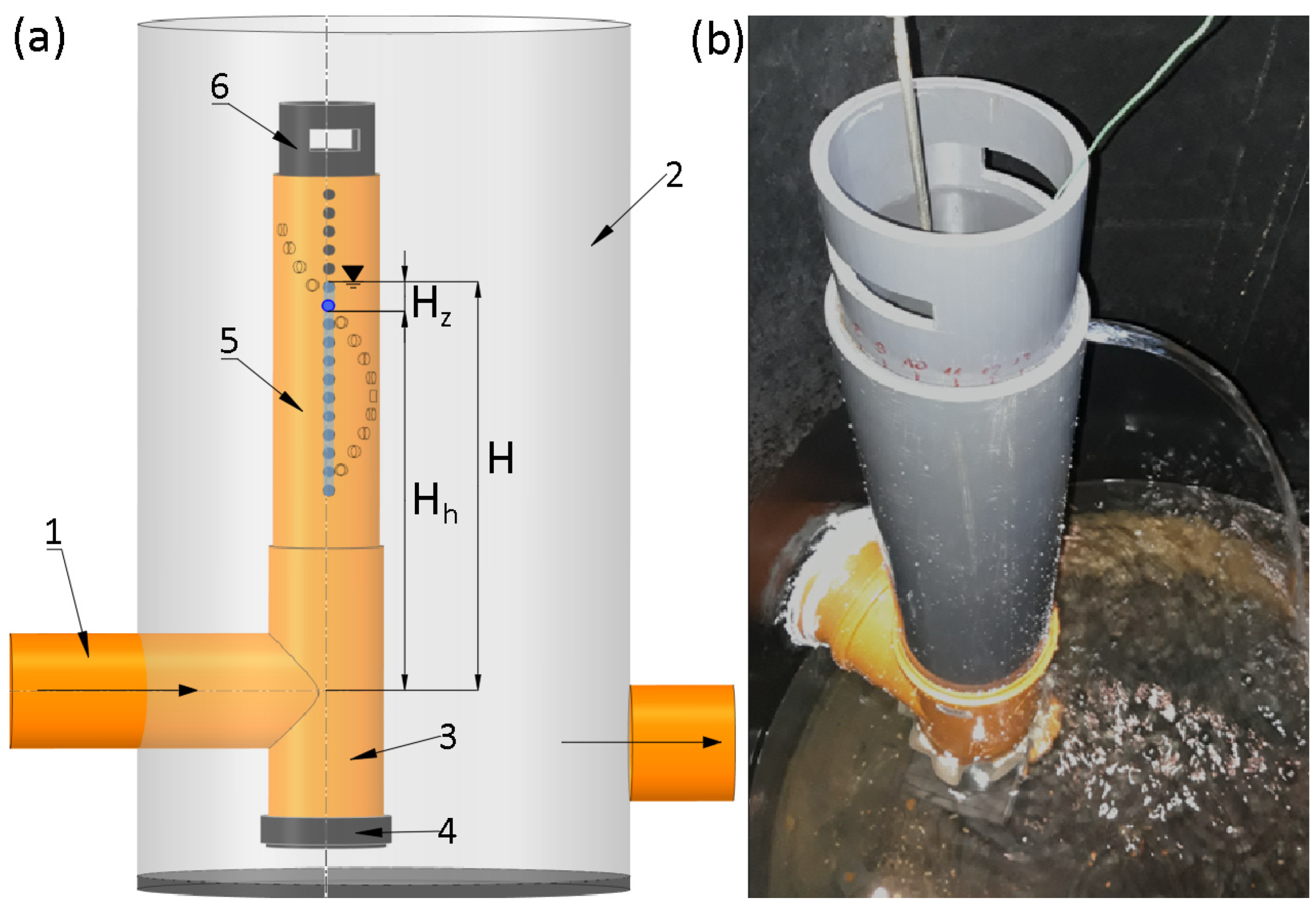
The hole regulator (Figure 1: 8b, Figure 3) consists of two pipes: external (5 in Figure 3) with a diameter of 150 mm and internal (6 in Figure 3) with a diameter of 140 mm. In both pipes, 49 cm from the lower edge of the regulator, there are 17 holes with a diameter of 15.5 mm. The holes in the outer pipe are arranged in a vertical line, while in the inner one, they are arranged helically with a shift from the vertical by 1.5 of the hole diameter. The required damming height is set by rotating the inner pipe to the position in which the given opening is unobstructed, i.e., when the openings in both pipes are clear. In the test specimen with a length of 65 cm, the height adjustment (Hh in Figure 3) of the position of the unobstructed opening was possible in the range of 19.5–61.0 cm in relation to the drain axis. With a high flow rate, when water overflows over the upper edge of the inner pipe of the regulator, regardless of the position of the holes, the maximum height of the adjustment is 70 cm in relation to the drain axis.
In the hole regulator, the regulating role is played by the holes made along a vertical line in the fixed outer tube (5 in Figure 3) and the spiral holes in the rotating inner tube (6 in Figure 3). The level adjustment effect is achieved by aligning two active openings by rotating the inner tube. The regulator is characterised in that the optimum water level in the vertical pipe is established within the height of a pipe. Water flows over the top of the inner pipe (6 in Figure 3) only when catastrophic flow occurs in the pipeline. The effective flow in the orifice regulator is shaped by the hydraulic losses in the gap between the vertical inner tube and the outer tube.
3. Results
3.1. Test Results of a Funnel Regulator
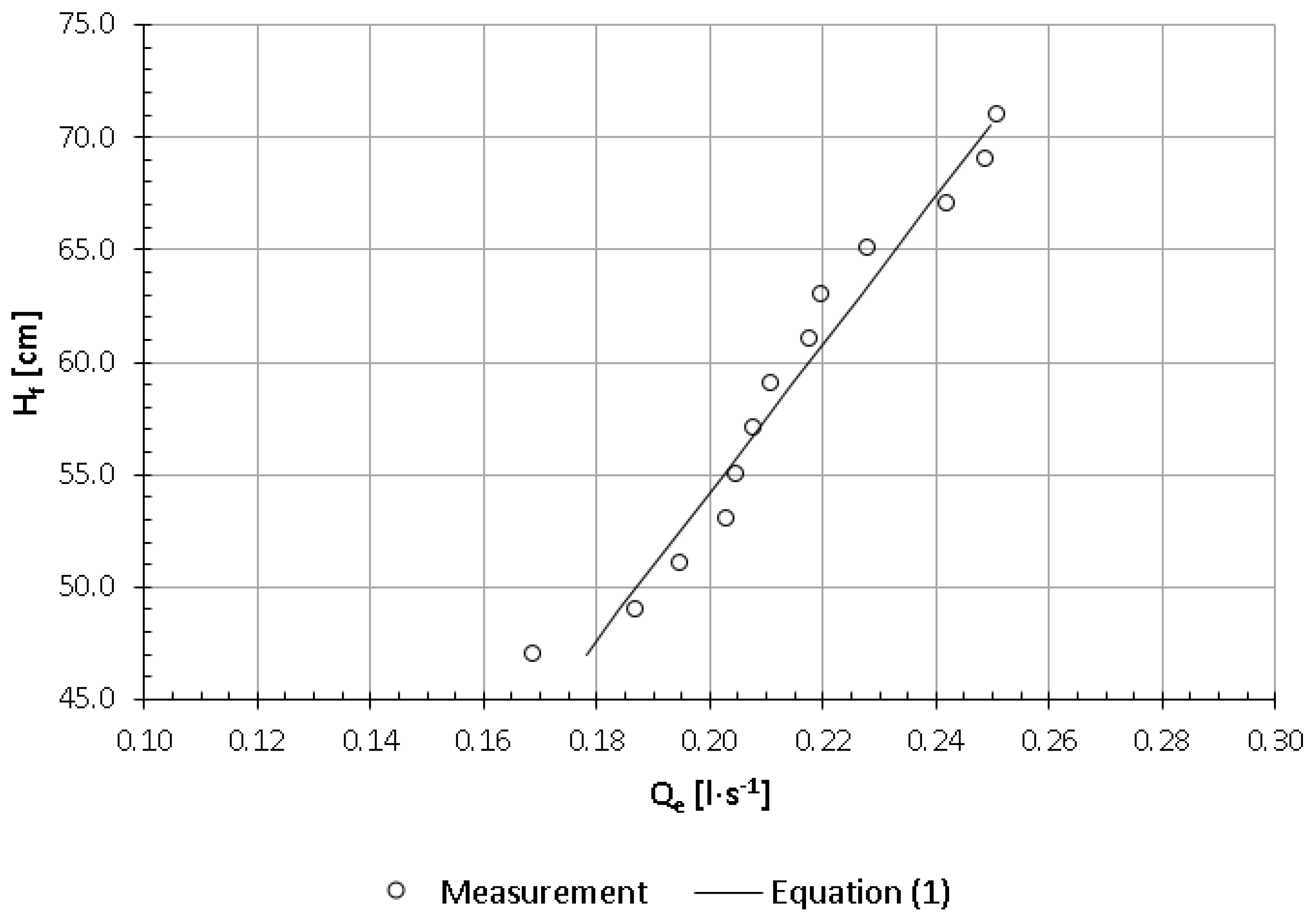
The funnel regulator is characterised by the presence of water flow through the threaded connection of the stem pipe with the stabilising ring. The water flow rate through the grooved thread of the socket regulator (Figure 2) increases with the height of the overflow edge, Hf. The value of the flow rate compensating for water losses on leaks, i.e., the effective flow Qe in the range of Hf = 47−71 cm, varies linearly in the range from Qe = 0.17 l·s−1 to Qe = 0.25 l·s−1 (Figure 4). From the operational side, Qe is the minimum effective flow after exceeding where the process of self-regulating the water level in the drainage pipeline begins. The curve of the dependence of the effective flow Qe on the height of the overflow edge, Hf, of the funnel regulator is presented in the following equation (coefficient of determination R2 = 0.960):
Qe = 0.00304Hf + 0.0352
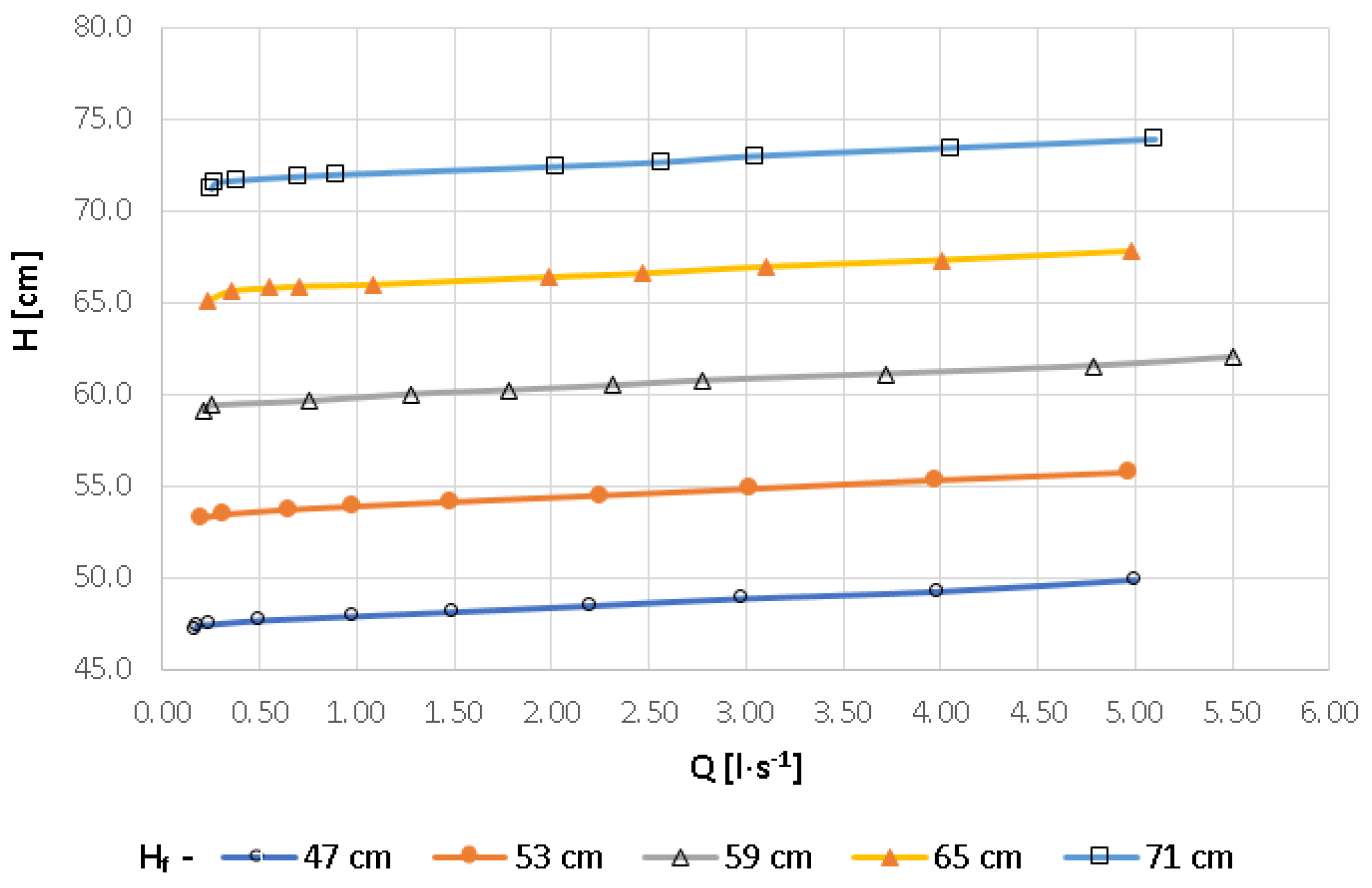
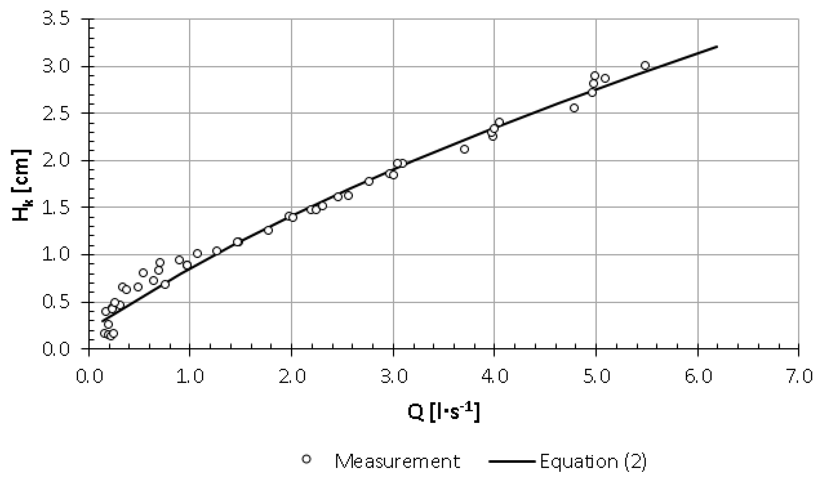
When the effective flow is exceeded, with a further increase in the flow rate in the drain, the damming height increases slightly in relation to the height of the overflow edge, Hf, which results from the relatively high expenditure of the socket overflow (Figure 5). At the same time, regardless of the height of the overflow edge in relation to the drain axis, the output of the socket overflow practically does not change. It is illustrated by the graph (Figure 6), which shows the collective curve of the spout overflow for the fifth height settings of the edge (Hf) of the regulator overflow in relation to the drain axis: 47, 53, 59, 65 and 71 cm. The equation of the flow rate curve of the socket regulator has the form Q = f(Hk), where Hk is the elevation of the water table in the shaft pipe axis above the edge of the funnel overflow (Figure 6):
After exceeding the value of the minimum effective flow Qe = 0.17−0.25 l·s−1, with the flow increasing to the maximum values of Q = 5.5 l·s−1, the height of the water layer above the overflow edge increases in the range of Hk = 0.12−3.0 cm. This means that in the tested range of flows, it is possible to obtain the assumed ordinate of water damming in the drain with a maximum adjustment range of up to +3.0 cm in relation to the set height H of the edge of the funnel overflow above the drain axis.
3.2. Test Results of the Hole Regulator
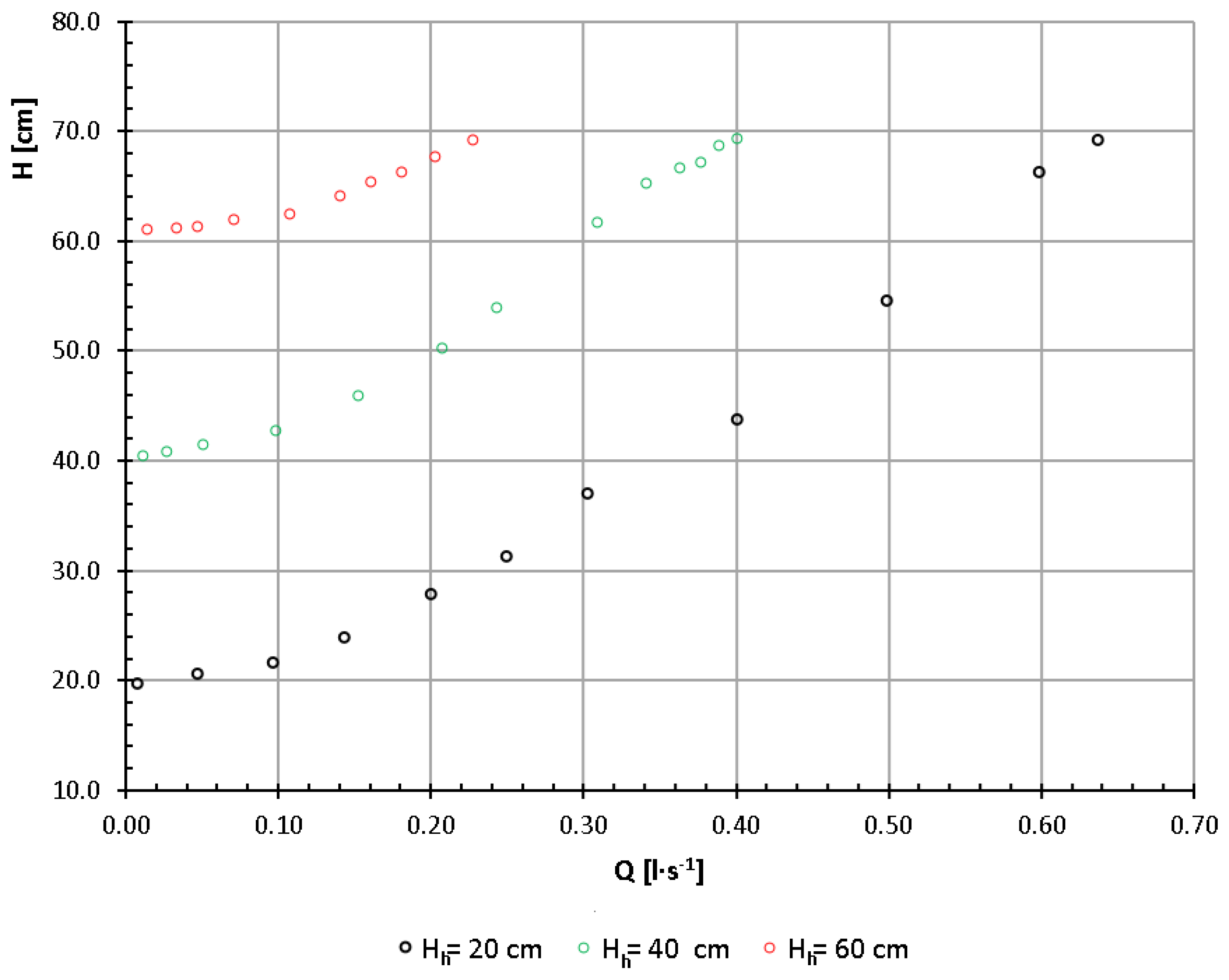
The design of the hole regulator ensures a tight connection of its outer pipe with the tee. Occurring leaks (creating the so-called effective flow) are caused by the gap between the inner and outer pipes, through which water penetrates not only into the exposed opening but also into the other one—located below the damming height. Figure 7 shows the flow rate curves of the regulator for the through positioning of selected openings at heights Hh of 20, 40 and 60 cm above the drain axis, for which the effective flow rate, necessary to obtain damming, equal to the height of the opening relative to the drain axis Hh, is Qe = 0.009 l·s−1 for an opening at the height of Hh = 20 cm, Qe = 0.012 l·s−1 for Hh = 40 cm and Qe = 0.015 l·s−1 for Hh = 60 cm.
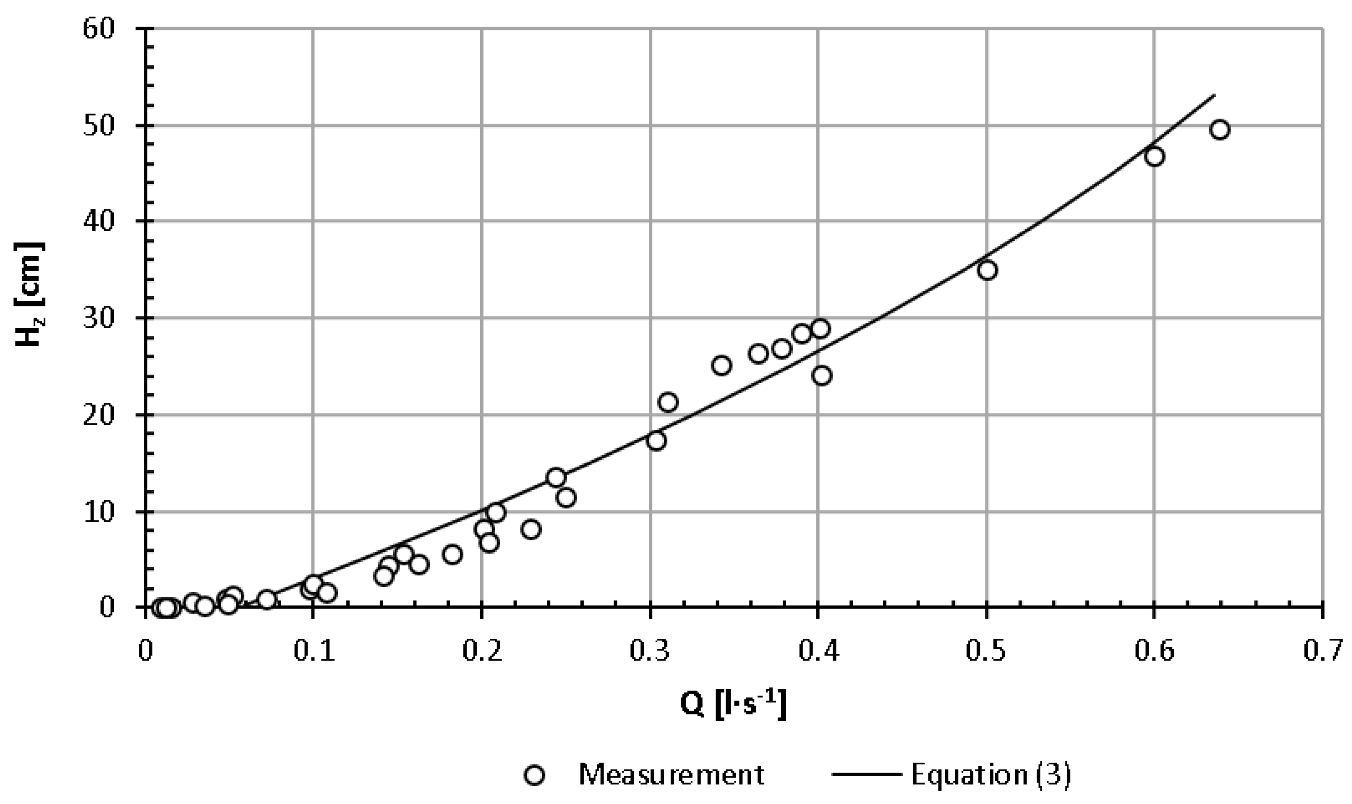
Figure 8 shows the expenditure curves of the tested holes for the water table height Hz, i.e., reduced with respect to the ordinates by the lower edge of each hole. The diagram shows that in the range of small values, i.e., up to 11−15 cm, the expenditures of individual holes are similar and reach the maximum value of Q = 0.25 l·s−1. After exceeding this value, the elevation of the water table above individual holes is characterised by increasing differentiation at the same hole volume. For example, at Q = 0.4 l·s−1, the elevation of the water table above the lower edge of the opening changes from 24 cm to 29 cm high. The reduced curve of the flow rate of the hole regulator openings, developed for intensities of up to Q = 0.65 l·s−1, is presented in Equation (3):
4. Discussion
In open drainage systems, gate regulators are usually used to regulate the flow and groundwater table level. These regulators are not applicable in underground pipe drainage systems. The article describes a pilot study of a new generation of rotary regulators; they are installed in wells/manholes. These are innovative solutions, the design of which is little known, and there are no publications on such solutions available. Their uncomplicated structure, principle of operation and adaptation to the currently existing drainage devices (drainages, manholes) are advantages that ensure the possibility of using them in existing drainage systems. However, the problem is leaks, defined in the work as effective flows Qe.
The funnel regulator is suitable for holding water in drains at flows equal to and greater than the effective flow, i.e., equal to the leakage water loss. At the damming height H = 47 cm, the value of this flow is Qe = 0.17 l·s−1; at higher dams, it increases linearly to Qe = 0.25 l·s−1 at H = 71 cm. With the flow increasing to the value of Q = 5.5 l·s−1, the increase in the damming height is small and amounts to +3.0 cm in relation to the edge of the socket overflow—regardless of the set height of the crown of the funnel overflow in relation to the drain axis.
The hole regulator is suitable for damming water in drains at low flow rates of up to Q = 0.25 l·s−1. With a variable flow in the range of 0.01−0.25 l·s−1, however, one should take into account the fluctuations in the damming height in the range of 11−15 cm in relation to the resulting height of the clear opening in relation to the drain axis. At flow rates greater than Q = 0.25 l·s−1, obtaining the required damming ordinate requires frequent changes to the unobstructed hole.
5. Conclusions
Based on the conducted research of regulators, the following conclusions and recommendations can be formulated:
- The funnel regulator, due to the relatively high flow rate of the funnel overflow, ensures a stable ordinate of damming water in a wide range of flow variability. The hole regulator is suitable for only damming water in drains at low flow rates of up to Q = 0.25 l·s−1.
- The tested regulators, due to leaks, can be used in practice only to partially delay the outflow of water from the soil. Leaks that cause Qe flow prevent precise regulation. The value of this flow varies depending on the height of the water level.
- It is recommended to conduct further research on the improvement of the connection of the main elements of the regulators in a way ensuring limitation of the size of effective flows.
Author Contributions
Conceptualisation, Z.P., S.B., P.S. and J.U.; methodology, Z.P., S.B., P.S. and J.U.; formal analysis, Z.P.; writing—original draft preparation Z.P. and S.B.; writing—review and editing, Z.P., S.B., P.S. and J.U.; visualisation, Z.P. and P.S.; supervision, Z.P., S.B., P.S. and J.U. All authors have read and agreed to the published version of the manuscript.
Funding
This research was funded by the Polish National Centre for Research and Development (grant no. BIOSTRATEG3/347837/11/NCBR/2017).
Institutional Review Board Statement
Not applicable.
Informed Consent Statement
Not applicable.
Data Availability Statement
Not applicable.
Acknowledgments
This study was done within the project Technological Innovations and System of Monitoring, Forecasting and Planning of Irrigation and Drainage for Precise Water Management on the Scale of Drainage/Irrigation System (INOMEL) under the BIOSTRATEG3 programme, funded by the Polish National Centre for Research and Development (contract no. BIOSTRATEG3/347837/11/NCBR/2017).
Conflicts of Interest
The authors declare no conflict of interest.
References
- Kundzewicz, Z.W.; Piniewski, M.; Mezghani, A.; Okruszko, T.; Pińskwar, I.; Kardel, I.; Hov, Ø.; Szcześniak, M.; Szwed, M.; Benestad, R.E.; et al. Assessment of climate change and associated impact on selected sectors in Poland. Acta Geophys. 2018, 66, 1509–1523. [Google Scholar] [CrossRef] [Green Version]
- Piniewski, M.; Szcześniak, M.; Kardel, I. CHASE-PL Future Hydrology Data Set: Projections of Water Balance and Stream-flow for the Vistula and Odra Basins, Poland. Water 2017, 2, 14. [Google Scholar] [CrossRef] [Green Version]
- Piniewski, M.; Marcinkowski, P.; Kundzewicz, Z.W. Trend detection in river flow indices in Poland. Acta Geophys. 2018, 66, 347–360. [Google Scholar] [CrossRef] [Green Version]
- Climate Change 2014 Synthesis Report. IPICC: Switzerland. 2015. Available online: https://www.ipcc.ch/site/assets/uploads/2018/02/SYR_AR5_FINAL_full.pdf (accessed on 20 October 2020).
- Design of A Counteraction Plan the Effects of Drought. State Water Holding Polish Waters, Poland. 2020. Available online: http://wide-vision.pl/wp-content/uploads/2020/05/Projekt-PPSS_25052020.pdf (accessed on 20 October 2020). (In Polish).
- Przybyła, C.; Szafrański, C. Water management problems in agriculture in Wielkopolska. Water Environ. Rural Areas 2004, 4, 25–38. [Google Scholar]
- Wilderer, P.A. Applying Sustainable Water Management Concepts in Rural and Urban Areas: Some Thoughts about Reasons, Means and Needs. Water Sci. Technol. 2004, 49, 8–16. [Google Scholar] [CrossRef]
- Mioduszewski, W. Management of water resources in rural areas: The Polish approach. J. Water Land Dev. 2006, 10, 3–14. [Google Scholar] [CrossRef]
- Kaca, E.; Drabiński, A.; Ostrowski, K.; Pierzgalski, E.; Szafrański, C. Water management in the agri-food sector and rural areas in conditions of new challenges and limitations. Pol. J. Agron. 2011, 7, 14–21. [Google Scholar]
- Mosiej, J.; Pierzgalski, E.; Jeznach, J. Contemporary conditions of water management in rural areas. Adv. Agric. Sci. 2011, 1, 25–36. [Google Scholar]
- Schuurmans, J.; Hof, A.; Dijkstra, S.; Bosgra, O.H.; Brouwer, R. Simple Water Level Controller for Irrigation and Drainage Canals. J. Irrig. Drain. Eng. 1999, 125, 189–195. [Google Scholar] [CrossRef]
- Ankum, P.; Renault, D. Modernization of Irrigation Systems—Technical Modules; FAO Land & Water Division: Masscote, Rome, Italy, 2008; pp. 1–32. Available online: http://www.fao.org/3/a-ap523e.pdf (accessed on 20 October 2020).
- Smedema, L.K.; Vlotman, W.F.; Rycroft, D.W. Modern Land Drainage: Planning, Design and Management of Agricultural Drainage Systems; CRC Press: Abingdon, VA, USA, 2004; p. 449. [Google Scholar]
- Skaggs, R.W.; Fausey, N.R.; Evans, R.O. Drainage water management. J. Soil Water Conserv. 2012, 67, 167A–172A. [Google Scholar] [CrossRef] [Green Version]
- Szejba, D.; Bajkowski, S. Determination of Tile Drain Discharge under Variable Hydraulic Conditions. Water 2019, 11, 120. [Google Scholar] [CrossRef] [Green Version]
- Bos, M.G. Discharge Measurement Structures. In International Institute for Land Reclamation and Improvement, 3rd ed.; International Institute for Land Reclamation and Improvement: Wageningen, The Netherlands, 1989; p. 402. [Google Scholar]
- Harada, M. Fluid Control and Measurement; The Society of Instrument and Control Engineers, Pergamon Press: Tokyo, Japan, 1986; Volume 1, p. 587. [Google Scholar]
- Bajkowski, S.; Szmigiel, T. Badania Modelowe Poziomej Komory Wirowej. Zesz. Nauk. Akad. Rol. Wrocławiu Ser. Inżynieria Sr. 1995, 266, 153–162. (In Polish) [Google Scholar]
- Bajkowski, S. Urządzenia wirowe w budownictwie wodnym. In Współczesne Problemy Inżynierii Wodnej; Majewski, W., Ed.; Politechnika Krakowska Wydział Inżynierii Środowiska: Kraków, Poland, 1997; Volume 1, pp. 199–209. (In Polish) [Google Scholar]
- Bajkowski, S. Discharge Coefficients of the Horizontal Vortex Chamber. Scientific Papers of the Agricultural University of Cracow. Zesz. Nauk. Akad. Rol. Krakowie Inżynieria Śr. 2001, 21, 673–681. (In Polish) [Google Scholar]
- Bajkowski, S. Hydraulic properties of horizontal vortex chamber. Adv. Hydro-Sci. Eng. 2002, 150, 47–58. (In Polish) [Google Scholar]
- Subhash, C.; Jain, M. Free-surface swirling flows in vertical dropshaft. J. Hydraul. Eng. 1987, 113, 1277–1289. [Google Scholar]
- Bajkowski, S. Kołowy przelew o ostrej krawędzi. Gospodarka Wodna 1985, 7, 160–163. (In Polish) [Google Scholar]
- Bajkowski, S. Submerged sharp-crested morning-glory-spillway criteria of submergence and the discharge coefficients. Model Investig. Hydro-Eng. 1987, 51, 5–17. [Google Scholar]
- Bajkowski, S. Submerged sharp-crested morning-glory-spillway criteria of submergence and the discharge coefficients. In Actual Problems of Hydro-Engineering. Model Investigations in Hydro-Engineering, Proceedings of the 3rd Conference, Wrocław, Poland, 27–29 April 1987; Majewski, W., Ed.; Technical University of Wrocław: Wrocław, Poland, 1987; pp. 5–15. [Google Scholar]
- Bajkowski, S. Strumień przelewowy upustu wieżowego—Planowanie badań laboratoryjnych. Zesz. Nauk. Akad. Rol. Krakowie, Ser. Inżynieria Sr. 2002, 23, 159–167. (In Polish) [Google Scholar]
- Voron, B. Regulation and management of water in irrigation canals and water saving irrigation methods and technologies. Houille Blanche 1995, 4, 72–81. [Google Scholar] [CrossRef] [Green Version]
- Frankenberger, J.; Kladivko, E.; Sands, G.; Jaynes, D.; Fausey, N.; Helmers, M.; Cooke, R.; Strock, J.; Nelson, K.; Brown, L. Drainage Water Management for the Midwest; Agricultural and Biosystems Engineering Extension and Outreach Publications: West Lafayette, IN, USA, 2004; 8p. [Google Scholar]
- Jaynes, D.B. Changes in yield and nitrate losses from using drainage water management in central Iowa, United States. J. Soil Water Conserv. 2012, 67, 485–494. [Google Scholar] [CrossRef] [Green Version]
- Sunohara, M.D.; Gottschall, N.; Craiovan, E.; Wilkes, G.; Topp, E.; Frey, S.K.; Lapen, D.R. Controlling tile drainage during the growing season in Eastern Canada to reduce nitrogen, phosphorus, and bacteria loading to surface water. Agric. Water Manag. 2016, 178, 159–170. [Google Scholar] [CrossRef]
- Sojka, M.; Kozłowski, M.; Stasik, R.; Napierała, M.; Kęsicka, B.; Wróżyński, R.; Jaskuła, J.; Liberacki, D.; Bykowski, J. Sustain-able Water Management in Agriculture—The Impact of Drainage Water Management on Groundwater Table Dynamics and Sub-surface Outflow. Sustainability 2019, 11, 4201. [Google Scholar] [CrossRef] [Green Version]
- Szymczak, T.; Kodura, A.; Kubrak, M. Water Level Controller in Drain Collectors. Patent Application No. P.426011, 2 January 2020. (In Polish). [Google Scholar]
- Sojka, M.; Stasik, R.; Napierała, M.; Wróżyński, R. Water Level Regulator, Especially in Drainage Network. Patent Application No. P.430541, 10 July 2019. (In Polish). [Google Scholar]
Figure 1.
Scheme of the entire test stand: 1—manhole; 2—down tank; 3—pump; 4—upper stability tank; 5—regulating valve; 6—electromagnetic flow meter; 7—precise water gauge staff; 8—rotary regulators of water damming in the drains: 8a funnel, 8b hole.
Figure 1.
Scheme of the entire test stand: 1—manhole; 2—down tank; 3—pump; 4—upper stability tank; 5—regulating valve; 6—electromagnetic flow meter; 7—precise water gauge staff; 8—rotary regulators of water damming in the drains: 8a funnel, 8b hole.

Figure 2.
Measurement scheme (a) and photo (b) of the funnel regulator: 1—drain; 2—drainage well; 3—tee; 4—drain plug; 5—stabilising ring (base); 6—threaded stem pipe; 7—funnel overflow; Hf—height of the funnel overflow edge position above the drain axis; Hk—water depth in the shaft pipe axis above the edge of the funnel overflow; H—height of the water level in the shaft pipe in relation to the drain axis.

Figure 3.
Measurement scheme (a) and photo (b) of a hole regulator: 1—drain; 2—drainage well; 3—tee; 4—drain plug; 5—outer pipe; 6—inner pipe; Hh—height of the open hole above the drain axis; Hz—water depth in the shaft pipe above the opened hole; H—height of the water level in the shaft pipe in relation to the drain axis.

Figure 4.
Effective discharge Qe of a funnel regulator, depending on the height of the funnel overflow edge position above the drain axis Hf.
Figure 4.
Effective discharge Qe of a funnel regulator, depending on the height of the funnel overflow edge position above the drain axis Hf.

Figure 5.
Curves of the overflow discharge Q of the funnel regulator at different heights of the water level in relation to the drain axis H.
Figure 5.
Curves of the overflow discharge Q of the funnel regulator at different heights of the water level in relation to the drain axis H.

Figure 6.
Cumulative curve of the overflow discharge Q of the funnel regulator at different values of Hk.
Figure 6.
Cumulative curve of the overflow discharge Q of the funnel regulator at different values of Hk.

Figure 7.
Flow discharge Q curves of the hole regulator for different heights Hh of the open hole.

Figure 8.
Reduced flow curve Q of the tested hole regulator openings.

Publisher’s Note: MDPI stays neutral with regard to jurisdictional claims in published maps and institutional affiliations. |
© 2021 by the authors. Licensee MDPI, Basel, Switzerland. This article is an open access article distributed under the terms and conditions of the Creative Commons Attribution (CC BY) license (http://creativecommons.org/licenses/by/4.0/).
Share and Cite
MDPI and ACS Style
Popek, Z.; Bajkowski, S.; Siwicki, P.; Urbański, J. Laboratory Tests of New Groundwater Table Level Regulators in Subsurface Drainage Systems. Water 2021, 13, 631. https://doi.org/10.3390/w13050631
AMA Style
Popek Z, Bajkowski S, Siwicki P, Urbański J. Laboratory Tests of New Groundwater Table Level Regulators in Subsurface Drainage Systems. Water. 2021; 13(5):631. https://doi.org/10.3390/w13050631
Chicago/Turabian StylePopek, Zbigniew, Sławomir Bajkowski, Piotr Siwicki, and Janusz Urbański. 2021. "Laboratory Tests of New Groundwater Table Level Regulators in Subsurface Drainage Systems" Water 13, no. 5: 631. https://doi.org/10.3390/w13050631
Note that from the first issue of 2016, this journal uses article numbers instead of page numbers. See further details here.