
Optimization and Analysis of a Slow-Release Permanganate Gel for Groundwater Remediation in Porous and Low-Permeability Media


Department of Geological Sciences, Ohio University, Athens, OH 45701, USA
*
Author to whom correspondence should be addressed.
Water 2021, 13(6), 755; https://doi.org/10.3390/w13060755
Submission received: 26 January 2021
/
Revised: 20 February 2021
/
Accepted: 3 March 2021
/
Published: 10 March 2021
(This article belongs to the Special Issue Novel Cost-Effective Remedial Techniques for Treating Organic and Inorganic Pollutants in Water Resources)
Abstract
:Dense nonaqueous phase liquids (DNAPLs) like trichloroethylene (TCE) serve as the most common form of groundwater pollution in the world. Potassium permanganate (KMnO4) is a strong oxidant that can quickly destroy DNAPLs into innocuous products. Slow-release permanganate gel (SRPG), a mixture of colloidal silica (CS) and KMnO4, has been recently developed as novel treatment option for dilute and large plumes of DNAPLs in groundwater. The objective of this study was to characterize and optimize gelling and release properties of a SRPG solution in saturated porous media. It was hypothesized that CS and KMnO4 content of the SRPG constrain gelation and release duration. Batch and column tests showed that gelation could be delayed through manipulation of the KMnO4 content. In column tests, silica content had little effect on the gelation lag stage and release rate but influenced duration of permanganate release. Flow tank tests comparing Bindzil 1440 (B-40) SRPGs with pure KMnO4 solutions under varying media conditions demonstrated that the presence of CS enhanced lateral spread and prolonged release duration of the oxidant.
1. Introduction
Dense nonaqueous phase liquids (DNAPLs) are a class of harmful organic chemical liquids that serve as the most abundant form of groundwater contamination in the world [1]. As DNAPLs are denser than water and relatively insoluble, they can infiltrate the subsurface until an impermeable layer is reached where they then accumulate to form pools and plumes [2]. Trichloroethylene (TCE) is a DNAPL of particular concern as it is the most common organic groundwater contaminant. A maximum contaminant level (MCL) for TCE in drinking water has been set at 5 μg/L [3].
In situ chemical oxidation (ISCO) techniques have become a common combative scheme against DNAPL contamination. In ISCO schemes, a strong chemical oxidant is injected into the subsurface via wells to react with and transform contaminants into environmentally innocuous by-products through a series of reaction steps [4]. Potassium permanganate (KMnO4) is an oxidant commonly used in ISCO schemes, but encounters a major problem, e.g., precipitation of the solid oxidation product manganese dioxide (MnO2) which results from rapid oxidation by permanganate (MnO4−). The MnO2 plugs pores in the subsurface which causes the oxidant to bypass contaminant zones, leading to a rebound in aqueous concentrations when flushing is terminated [2].
The objective of this study was to characterize and optimize gelling and release properties of a slow-release permanganate gel (SRPG) as a novel low-cost treatment option for large, dilute DNAPL plumes in groundwater. The SRPG is a mixture of KMnO4 and colloidal silica (CS) which serves as a gelling agent. The SRPG may address problems that persist in other ISCO schemes, e.g., lack of lateral spreading when using slow-release KMnO4 pellets [5] and pore plugging due to MnO2 precipitation with KMnO4 flushing schemes [6]. First, the injection of the SRPG as a liquid can allow MnO4− to spread laterally, facilitating mixing between the oxidant and contaminant. As MnO4− is released slowly through a gelled CS matrix and oxidize dilute dissolved TCE plume, the SRPG should also produce less MnO2 precipitation.
Lee and Gupta [7] previously demonstrated gelation lag times up to 6 h in saturated, porous media through manipulation of the KMnO4 concentration ([KMnO4]) in column flow-through tests with Bindzil 1440 CS. The specific objective of this study was to further optimize SRPG to obtain a more desirable gel lag time, release rate, and release duration in saturated, porous media with flowing water. Ideal conditions were set at a gel lag time ≥3 d, a release rate ≥850 μg/d, and a release duration ≥3 wk. These values were chosen as benchmark variables based on the time and amount of KMnO4 required to travel 1.5 m from injection wells at a flow rate of 0.5 m/d to degrade a TCE plume of 100 μg/L to concentrations less than the MCL (5 μg/L). It was hypothesized that CS and KMnO4 content of the SRPG constrain gelation and release duration. A higher silica and KMnO4 content was expected to combat dilution by providing more opportunities for interparticle interaction. This would promote the formation of siloxane Si–O–Si bonds, and thus yield a stronger gel that would reduce permeability and contact with water per surface area [7,8].
Permanganate can diffuse into low-permeability units and counter-diffuse back into groundwater over time [9,10,11]. Therefore, a portion of this study was also devoted to testing the SRPG solution in porous media with a low-permeability lens. It was hypothesized that the low-permeability media could serve as a secondary slow-release system to prolong the release duration of the SRPG. Fractures in low-permeability layers were expected to further enhance the release duration.
2. Background
2.1. Potassium Permanganate as an Oxidizing Agent
KMnO4 is a strong oxidant (Eo = 1.68 V) and a highly water soluble (64 g/L at 20 °C) inorganic compound. Due to its strong oxidizing capacity, it has become one of the most widely used compounds in contaminated water remediation over the last 20 years [10,12,13]. Ultimately, MnO4− oxidation of TCE produces MnO2 precipitates, chloride, carbon dioxide gas, and acidity [4,14]. The overall net reaction can be written as [2]:
C2HCl3 + 2 MnO4− → 2 MnO2 (s) + 2 CO2 (g) + 3 Cl− + H+
KMnO4 is advantageous as an oxidizing agent as it remains relatively stable in the subsurface, is effective over a wide pH range, and is relatively inexpensive [14]. MnO4− also has a relatively slow reaction rate which allows it to travel greater distances in zones with average to high permeability and to diffuse into zones with low permeability [15].
2.2. Colloidal Silica as a Gelling Agent
Colloidal silica is a sol, or solution consisting of nanoparticles of amorphous silicon dioxide (SiO2) suspended in aqueous phase in water [7,13]. To prevent premature gelation, CS solutions are typically stabilized during manufacturing by elevating the pH with alkaline solutions such as sodium hydroxide (NaOH). This negatively charges the particles so that they repel each other, thus prohibiting gelation [16,17].
Results from previous studies suggest that CS should serve as an effective gelling agent with KMnO4. CS has small particles capable of traveling through porous media, is nontoxic, is biologically and chemically inert, and is durable [18]. In addition, CS has the benefit of a modifiable gelation time for desirable longitudinal, transverse, or vertical transport [7].
Control over gelation rate is important so that the SRPG solution can be modified to travel a desired distance to the contaminant before becoming so viscous that transport is restricted [17]. Sol-gel aggregation is influenced primarily by ionic strength and pH but can also be affected by factors such as temperature, particle size, and silica concentration [8,17]. In general, the gelation time of CS is decreased by increasing the ionic strength [17]. With addition of a salt such as K+, the particles in the CS solution lose their repulsive forces and siloxane bonds can form [16]. The relationship between pH and gelation rate is parabolic. At pH ≥ 8, the particles will bear a slightly negative charge to drive interparticle repulsion. The most rapid gelation rate occurs at a neutral to slightly acidic pH, and when the pH drops below 5, the attraction between particles is lost [8,16,19].
2.3. The Slow-Release System
For groundwater remediation, slow-release MnO4− serves as a semi-passive option for the in situ remediation of TCE [4]. The SRPG implements a matrix-type slow-release system in situ in which there are multiple pockets of MnO4− distributed within a matrix. In a matrix-type slow-release system, oxidant release is governed by diffusive transport through secondary permeability formed within the matrix [5]. As MnO4− on the edges of the CS matrix is released, secondary permeability would be created which allows for the slow release of MnO4− farther inside the matrix by diffusion through the permeable outer gel matrix. This causes an increase in the diffusion length within the matrix over time. As a result, there would be an initially high spike in [MnO4−] followed by its gradual decline [2].
As solution can diffuse into and counter-diffuse from low-permeability units [9,10,11], part of this study focused on testing the feasibility of producing a secondary slow-release system in situ with the injection of SRPG solution. It was expected that as a gel, the SRPG should be able to offer more lateral area for diffusion of MnO4− into a clay matrix compared to a pure KMnO4 solution mainly due to the higher viscosity of the gel. During counter-diffusion, this should allow the SRPG to behave as a long-term source of MnO4− to target DNAPLs. Solpuker et al. [11] investigated the transport of KMnO4 mixed with ultra-dense silicate solutions in porous media containing low-permeability layers and lenses. Even in the silicate matrix, MnO4− was capable of diffusing into a low-permeability clay lens. In the first 2 d, the MnO4− infiltrated the clay where it remained emplaced for ~11 d. It took ~1 month for the MnO4− to be depleted from the tank. DNAPLs often gather near low-permeability units, and this tendency could be exploited to extend the release duration of the oxidant in the target zone.
3. Materials and Methods
3.1. Gelation Batch Tests
SRPG solutions were produced by mixing granular KMnO4 (ACS reagent, ≥99%) from Sigma-Aldrich with 50 mL of one of six types of CS from Wesbond Corporation, Nalco Company and Grace: Bindzil 1440 (B-40), Bindzil 9950 (B-50), Nalco 1142 (N-40), Megasol S50 (M-50), Ludox TM-40 (L-40), or Ludox TM-50 (L-50). The specifications for the CS solutions are outlined in Table 1. SRPG solutions were also manufactured with matrices consisting of 25 mL of a 40 wt.% CS solution mixed with 25 mL of a 50 wt.% CS solution. After mixing, the SRPG solution was deposited into a 50 mL high-density polyethylene container, covered with plastic wrap, and placed under a fume hood to maintain constant temperature. Gel times were estimated for SRPG solutions through visual observations. The pH of CS solutions was measured with a pH meter (IQ Scientific Instruments), and viscosity was measured from 20 g/L SRPG solutions with a viscometer (HAAKE Viscotester 2 Plus, Thermo Fisher Scientific, Waltham, MA, USA).
3.2. Column Flow-Through Tests in Porous, Saturated Media
Two-dimensional column flow-through tests served as preliminary tests to select the best candidate SRPG solutions to be used later in larger scale 3-dimensional flow tank tests and to understand the effects of saturated media conditions on different types of SRPGs. Column tests were conducted in KONTES Chromaflex columns with dimensions (L × ID) of 120 cm × 4.8 cm (V = 2.17 L) and 17.5 cm × 5.7 cm (V = 0.45 L). Silica sand (sieve size = 60–100 mesh) served as porous media and was fully saturated with water to an estimated porosity of 0.3. Columns were oriented horizontally with the inflow end slightly elevated and the lid on the outflow end loosened to create a pressure gradient. A peristaltic pump (Masterflex L/S, Cole-Parmer, Vernon Hills, IL, USA) injected the SRPG solution into the column, and deionized water was then pumped into the column at an ambient flow rate of 0.6 mL/min.
Once MnO4− was present in the effluent, samples were collected in a vial from the outlet approximately every 1 to 3 h. This time was adjusted for later trials of each test. Samples were tested in the UV-Visible Spectrophotometer (λ = 525 nm) to measure [MnO4−] and photographs were taken to document visual observations of the migration and release patterns.
3.3. Small Flow Tank Tests in Porous and Low-Permeability Media
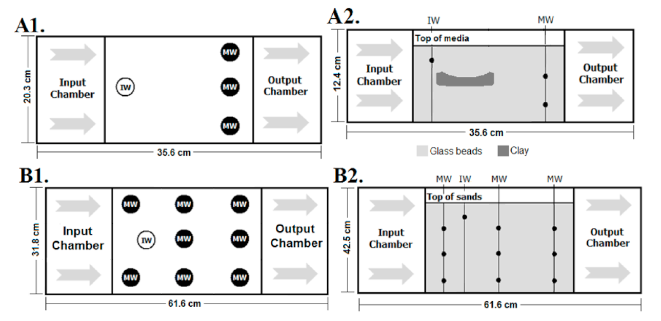
Flow tank tests were conducted to compare the dynamics and release characteristics of 50 mL of a 26 g/L B-40 SRPG solution to a pure KMnO4 solution of equal concentration and volume. Small flow tanks (L × W × H = 35.6 cm × 20.3 cm × 12.4 cm, V = 5.7 L) were constructed by dividing polypropylene containers into an inflow chamber, an outflow chamber, and a central chamber in which media were set. Mil-10 Ballotini industrial glass beads (Potters Industries, Inc.; sieve size = 100–170 mesh) served as porous media with an approximate porosity of 0.4 and Wyoming bentonite powder (Best Bentonite; sieve size = 200 mesh) was used to form clay. Three different media conditions were established: all-porous media, porous media with an intact clay lens, and porous media with a fractured clay lens. Clay lenses were ~3 cm thick and ~7 cm long with an underlying layer of beads ~2 cm thick and top layer of beads ~3 cm thick. A peristaltic pump supplied water to the inflow chamber to maintain a background flow rate of 0.6 mL/min throughout testing.
Injection and monitoring wells were constructed by shaping stainless steel screens into cylinders and filling them with fiberglass as a filter and Teflon tubing for solution delivery and sample extraction. The injection well was at the upstream end of the tank and ~2 cm below the surface. Three multi-level monitoring wells were placed ~15 cm downstream from the injection well, spaced ~5 cm apart, and collected samples from depths of ~3 cm and ~6.5 cm. Figure 1A illustrates the set-up for the flow tank. Samples were collected approximately every 12 h for the first day of testing and then daily until MnO4− was depleted from the tank. [MnO4−] was measured with the UV-Visible Spectrophotometer (λ = 525 nm) and photographs were taken throughout testing to record MnO4− release and migration. After a flow tank test completed, the clay was extracted to observe oxidation behavior and residual MnO4− concentrations.
3.4. Large Flow Tank Test in Porous Media
A large flow tank test was set up in a fashion similar to the small flow tank tests to monitor the migration and release of 150 mL of a 26 g/L N-40/B-50 mix SRPG in porous media in greater detail. A glass tank (L × W × H = 61.6 cm × 31.8 cm × 42.5 cm, V = 83.25 L) was divided into an inflow chamber, central chamber, and outflow chamber. The central chamber of the flow tank was filled with Mil-10 Ballotini industrial glass beads to a depth of ~40 cm, length of ~50 cm, and porosity of ~0.4. After media were set, a peristaltic pump released water into the inflow chamber at a flow rate of 21.0 mL/min. Solution delivery was performed through an injection well ~4.5 cm below the surface.
Multi-level monitoring wells extracted samples from depths of ~10 cm, ~25 cm, and ~38 cm below the media surface. The monitoring wells were spaced ~13 cm apart from any side and positioned in parallel rows as depicted in Figure 1B. The first central monitoring well was ~11 cm from the injection well. Samples were collected approximately every 12 h and were then tested in the UV-Visible Spectrophotometer (λ = 525 nm) to assess [MnO4−].
4. Results and Discussion
4.1. Gelation Dynamics of the SRPG
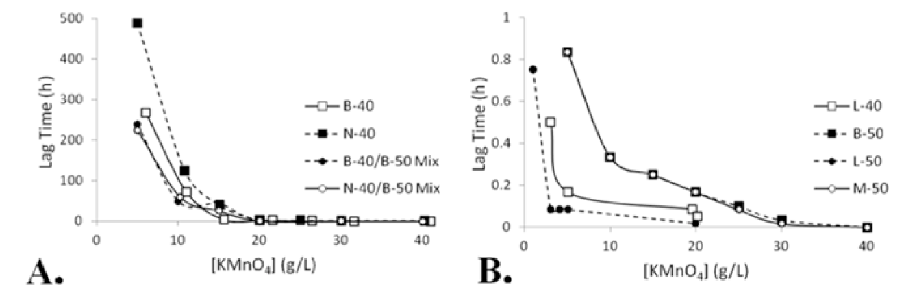
Regardless of CS type, a two-stage increase in viscosity was observed in all SRPG solutions at some KMnO4 concentration ([KMnO4]). Furthermore, observations from batch tests suggested that [KMnO4] was the primary variable to influence sol-gel aggregation of CS. As the [KMnO4] increased, the gelation lag time decreased. Figure 2 depicts this pattern. A two-stage increase in viscosity was also supported by viscosity measurements. For continuity, viscosity tests were performed on SRPG solutions at a [KMnO4] of 20 g/L, and a gelation threshold was set at 1000 cP. Visual observations and gel state data [18] suggest that at this viscosity the SRPG has started to gel and should stop spreading in media. Viscosity tests showed that the 20 g/L B-40 and N-40 SRPGs both underwent lag periods > 2 h.
Of all the CS solutions, the N-40 yielded SRPGs with the greatest gelation lag time. As Figure 2 shows, a 5.0 g/L N-40 SRPG solution demonstrated a lag time >20 d, followed by a 6.0 g/L B-40 SRPG at >11 d. SRPG solutions with matrices composed of a half 40 wt.% and half 50 wt.% mix of CS exhibited appreciable lag times. A 5.0 g/L B-40/B-50 mix SRPG solution took nearly 10 d before gelation was achieved, and a 5.0 g/L N-40/B-50 mix SRPG reached gelation in ~9 d. All other types of CS created SRPGs with maximum lag times < 1 h. In addition to their low lag times, the L-40 and L-50 SRPG solutions had a significantly more limited range of [KMnO4] they could hold before immediate gelation. It was also observed that the M-50 SRPG behaved in a manner nearly identical to the B-50.
The B-40, N-40, and L-40 CS solutions all have a 40 wt.% silica concentration. However, the B-40 and N-40 SRPG solutions achieved much greater lag times than the L-40 SRPGs (Figure 2). The reason for the lower lag time of the L-40 compared to the B-40 and N-40 CS solutions was attributed to its lower pH. To acquire a more accurate value of the pH, pH measurements were collected from CS solutions as shown in Table 1. Zeta potential becomes increasingly negative with increasing pH [24]. Around pH 8, the repulsion between particles becomes so strong that they cannot form siloxane bonds. Thus, gelation occurs most rapidly at a neutral to slightly acidic pH when the zeta potential is low and van der Waals attraction can overcome interparticle electrostatic repulsion [8,16]. As the L-40 CS had a lower pH, repulsion between particles was initially weaker. Addition of the salt K+ reduced the zeta potential further, allowing for more interparticle interaction and the formation of siloxane bonds at a faster rate.
Particle size may have also influenced the rate of gelation. The L-40, B-40, and N-40 CS solutions had particle diameters of 22 nm, 14 nm, and 8 nm, respectively. In viscosity tests, the L-40 SRPG broke the gelation threshold first followed by the B-40 SRPG and finally the N-40 SRPG. Furthermore, the L-40 SRPG had the shortest max gelation lag time while the B-40 SRPG had an intermediate lag time, and the N-40 SRPG had the greatest lag time. This is consistent with observations that increasing particle size is associated with greater opportunities for interparticle interaction for the formation of siloxane bonds that cause gelation [8].
4.2. Column Flow-Through Test Results
Compared to batch tests, the overall gelation lag time for the SRPGs was delayed in column flow-through tests. Furthermore, some lower KMnO4 concentrations were unable to achieve gelation. These outcomes were attributed to dilution effects due to hydrodynamic dispersion.
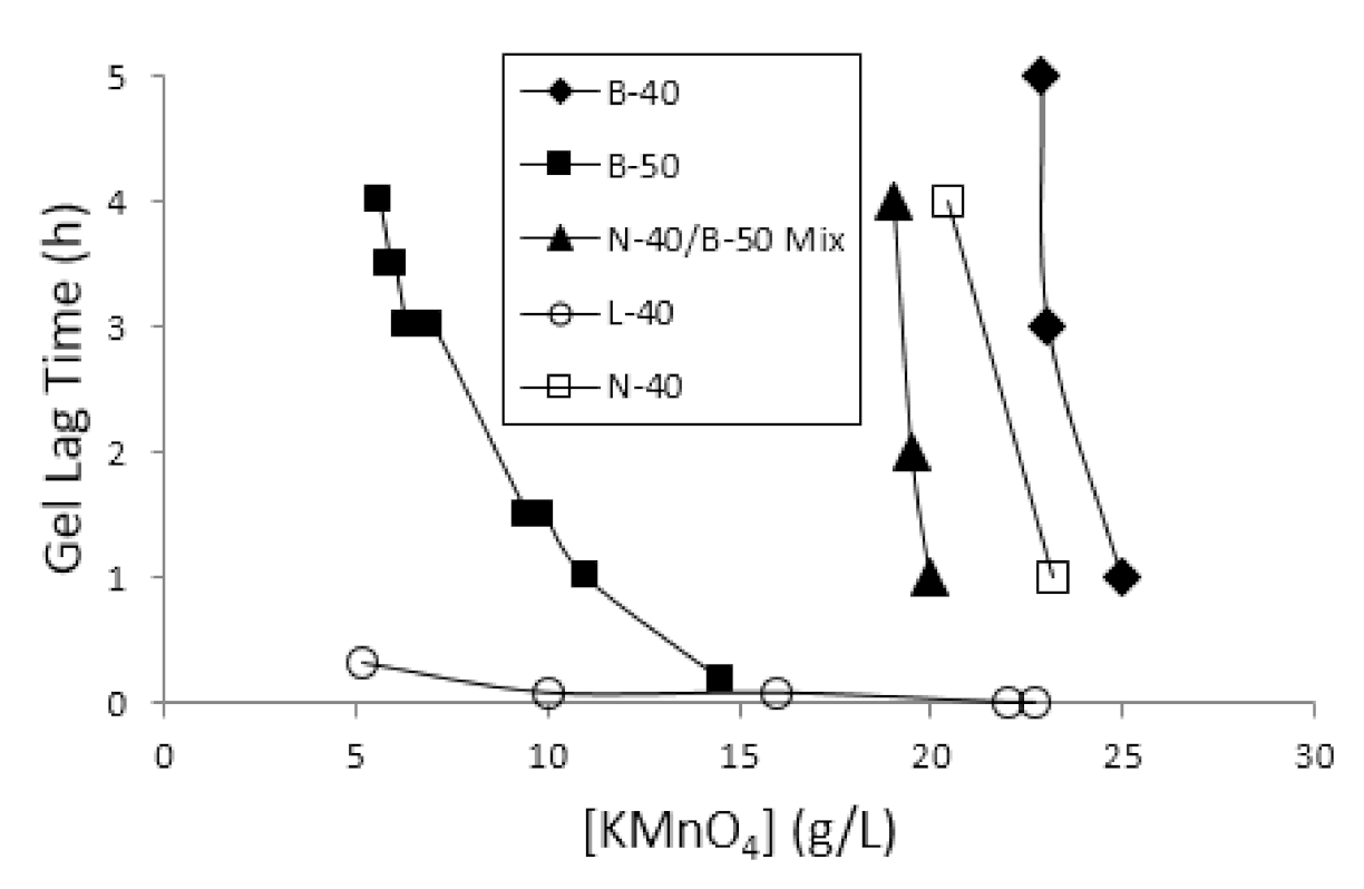
As Figure 3 shows, the B-40 SRPG solution was unable to achieve gelation at an initial [KMnO4] of 21.0 g/L, and at a [KMnO4] of 22.9 g/L, the solution attained a maximum gel lag time of ~5 h. The N-40 SRPGs demonstrated gelation in a similar [KMnO4] range to the B-40 SRPGs, gelling in ~3 h at a [KMnO4] of 20.4 g/L, but were unable to reach gelation at a [KMnO4] of 18.0 g/L. Batch tests previously revealed that the N-40 SRPGs achieved much longer lag periods than the B-40 SRPGs at the same [KMnO4]. This slower increase in viscosity resulted in more vulnerability to dilution effects, therefore explaining the inability of the N-40 SRPGs to reach longer lag times in saturated media.
Compared to B-40 and N-40 SRPGs, the B-50 SRPG solutions gelled at much lower KMnO4 concentrations. B-50 SRPG solutions were unable to gel at a [KMnO4] of 5.1 g/L and gelled in ~4 h at a [KMnO4] of 5.6 g/L. The ability of these SRPGs to gel on a lower [KMnO4] scale and over a wider range of concentrations was indicative that the higher silica content of the B-50 CS provided a resistance to dilution by providing enhanced gelling properties. Like in batch tests, the M-50 SRPG solutions demonstrated very similar gelation behavior to B-50 SRPGs at the same [KMnO4] in column tests, so they were excluded from further testing.
Gelation occurred so quickly, that almost none of the L-40 and L-50 SRPG solutions permitted low-pressure injection. Only a 5.2 g/L L-40 SRPG solution was able to be injected and reach gelation, but this solution gelled within 20 min. A 1.0 g/L L-50 SRPG solution was able to be injected but did not gel.
N-40/B-50 mix SRPGs exhibited gelation lag times at KMnO4 concentrations comparable to the N-40 and B-40 SRPGs. A 19.0 g/L N-40/B-50 mix SRPG solution achieved gelation in ~4 h, but no gel was formed at a [KMnO4] of 18.0 g/L.
All SRPG solutions yielded release rates greater than the benchmark of 850 μg/d. For example, the average mass flux for all B-40 and B-50 SRPG solutions were over 100 times greater than the benchmark at 216.2 mg/d (SD = 111.5 mg/d) and 205.3 mg/d (SD = 128.1 mg/d), respectively. Statistical analyses showed that silica concentration had little effect on the release rate of the SRPGs. No significant difference was found in mass flux between the B-40 and B-50 SRPG solutions (t(14) = 0.16, p = 0.87). In addition, no significant correlation was found between mass flux and [KMnO4] with either the B-40 SRPGs (r(3) = 0.85, p = 0.07) or the B-50 SRPGs (r(9) = −0.40, p = 0.23).
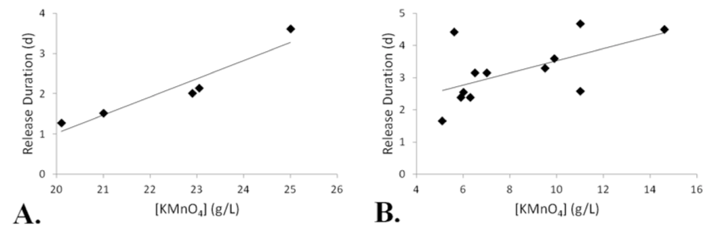
Release duration was also monitored during column tests. It should be noted that the release duration included measurements of [MnO4−] below the detectable limit. When below this threshold, the presence of MnO4− was confirmed by the purple discoloration of the effluent. The B-40 SRPGs demonstrated release durations ranging from 1.3 to 3.6 d (Ra = 2.3 d) with an average release duration of 2.1 d (SD = 0.9 d). Release durations of the B-50 SRPGs were significantly greater than those from the B-40 SRPG solutions (t(15) = 2.16, p = 0.05). B-50 SRPG release durations ranged from 1.7 to 4.7 d (Ra = 3.0 d) with an average release duration of 3.2 d (SD = 0.95 d). Furthermore, a significant linear trend between [KMnO4] and release duration was observed in both the B-40 SRPGs (r(3) = 0.95, p = 0.01) and the B-50 SRPGs (r(10) = 0.58, p = 0.05) as shown in Figure 4.
A summary of the column tests by maximum gel lag time can be found in Table 2. No SRPG solutions reached the benchmark lag time of 3 d. While the increased silica content did allow SRPG solutions to gel at lower KMnO4 concentrations, it did not produce a longer lag period. The 40 wt.% B-40 SRPG demonstrated the greatest lag time at ~5 h. The B-50 and N-40/B-50 mix SRPGs had slightly lower maximum lag times of ~4 h. Although all SRPGs achieved the benchmark release rate of 850 μg/d, release duration was relatively short with the longest duration being ~5 d from an 11.0 g/L B-50 SRPG. These results, however, did suggest that the higher silica concentration of B-50 SRPGs yielded significantly higher release durations than B-40 SRPGs.
4.3. Small Flow Tank Test Results
Small-scale flow tank tests were conducted with two main purposes: to compare the 3-dimensional spread and release characteristics of a B-40 SRPG against a pure KMnO4 solution of equal concentration and volume and to observe how different media conditions influence the migration and release of the SRPG. Based on batch and column test results, a B-40 SRPG containing 26 g/L KMnO4 was chosen for its ability to gel in saturated media and for its ease of injection compared to SRPGs with a higher silica concentration. In addition, the B-40 SRPGs achieved higher gel lag times and could hold higher KMnO4 concentrations than the 50 wt.% CS SRPGs.
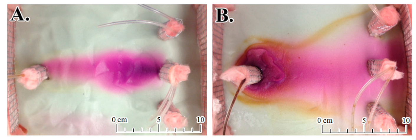
In all-porous media, the CS in the solution nearly tripled the distance of lateral dispersion of the oxidant compared to a pure KMnO4 solution as depicted in Figure 5. Visual observations suggested that the KMnO4 solution extended laterally ~5 cm. Measurements of [MnO4−] could only be extracted from the central well, adding further support that there was very little lateral dispersion of the oxidant from the KMnO4 solution. The CS in the SRPG, however, resulted in a noticeable gel near the injection point and lengthened the lateral distance of MnO4− to ~14 cm. In terms of vertical dispersion, CS appeared to increase the density of the solution resulting in higher [MnO4−] measurements deeper in the tank from the SRPG than from the KMnO4 solution.
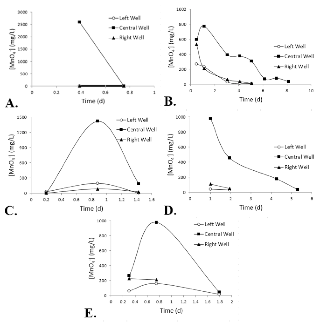
The KMnO4 solution also demonstrated little potential for sustainable release in all-porous media as observed in Figure 6A. For simplicity, measurements were averaged between the two depths at which samples could be drawn to focus on lateral spread. The KMnO4 solution exhibited peak release at a mean [MnO4−] of 2591 mg/L within 9 h of injection. This high release of MnO4− resulted in a low release duration, ~18 h. The SRPG provided greater control over MnO4− release, with a peak mean [MnO4−] of 773 mg/L at the central monitoring well ~27 h after injection as shown in Figure 6B. As a result, the CS prolonged the release duration to 9.2 d.
When placed in porous media with a clay lens, the SRPG was again able to spread more laterally compared to the pure KMnO4 solution. Surficial observations suggested that the KMnO4 solution had a lateral extent of ~8.5 cm, but [MnO4−] measurements were collected from all three monitoring wells which suggested a minimum lateral extent of 10 cm. With the SRPG, MnO4− and oxidation of the clay could be observed on both sides of the tank, indicating that MnO4− occupied the tank to the fullest lateral distance permitted, ~20 cm.
Measurements of [MnO4−] from monitoring wells suggest that the clay lens did limit MnO4− release for both the KMnO4 solution and the SRPG. Under these media conditions, the two solutions behaved in a manner relatively similar to observations made in the all-porous media. Peak release occurred in the KMnO4 solution sooner and with higher amounts of the oxidant released resulting in a shorter release duration than the SRPG. As Figure 6C,D demonstrate, the peak mean concentration released from the 26 g/L KMnO4 solution was reduced from 1491 mg/L to 976 mg/L at the central well when CS was included in the solution. The presence of CS also delayed peak release in the KMnO4 solution, this time from ~21 h after injection to ~24 h and elicited a more gradual release of MnO4− which extended the release duration from 31 h to 4.6 d.
When comparing the SRPG under different media conditions, the presence of clay both contributed to a more dramatic decline in the amount of [MnO4−] in the system and reduced the release duration of the oxidant. As Figure 6B,D,E illustrate, the SRPG in all-porous media experienced a peak release ~27 h after injection but a peak release was observed ~24 h after injection in the media with a clay lens and ~21 h after injection when the clay lens was fractured. Similarly, the release duration of the SRPG was lowered from 9.2 d in the all-porous media to 4.6 d in the presence of the clay lens. When the clay was fractured, the release duration was reduced further to 38 h.
It was expected that MnO4− release could be prolonged by diffusion into the clay matrix and a secondary slow-release system could be developed in situ through counter-diffusion. The clay lens appeared to mediate release from the KMnO4 solution to yield lower MnO4− concentrations and a longer release duration. However, the release duration was significantly reduced by the clay lens for the SRPG solutions.
One explanation for the diminished release duration of the SRPG solutions is that the natural oxidant demand (NOD) of the clay media resulted in some MnO4− loss. This could also explain the release behavior of the KMnO4 solution. Rather than mediating MnO4− release, the clay lens hindered migration of the KMnO4 solution over time due to its low permeability, explaining the higher release duration. Meanwhile, NOD led to a reaction between KMnO4 and the clay to result in lower measurements of [MnO4−]. Organic carbon is one of the largest contributors to NOD in clay materials. The reaction between organic carbon and KMnO4 can be written as [25]:
3 CH2O + 4 MnO4− → 3 CO2 + 4 MnO2 (s) + H2O + 4 OH−
Marshall et al. [26] analyzed organic carbon content of Wyoming bentonite clay samples and found it composed 0.11 to 0.24 wt.% of the samples. Excavation of the clay lenses supported the notion that MnO4− had been consumed through NOD. A significant area of dark MnO2 precipitates could be observed on the outer edges of the clay that extended ~2 to 4 cm inward while no residual MnO4− was observed. This also helps explain why release duration was shorter in the fractured clay. Due to the fractures, MnO4− contact was not limited to the outer edges but could also infiltrate into the clay. This supplied more surface area for oxidation to occur. Oxidant consumption is greater with increasing initial [MnO4−] [27]. As MnO4− was released slowly from the SRPG, the initial concentration in contact with the clay lens was lower than that from the KMnO4 solution. Consequently, the SRPG solution achieved a much greater release duration than the KMnO4 solution in media with a clay lens.
4.4. Large Flow Tank Test Results
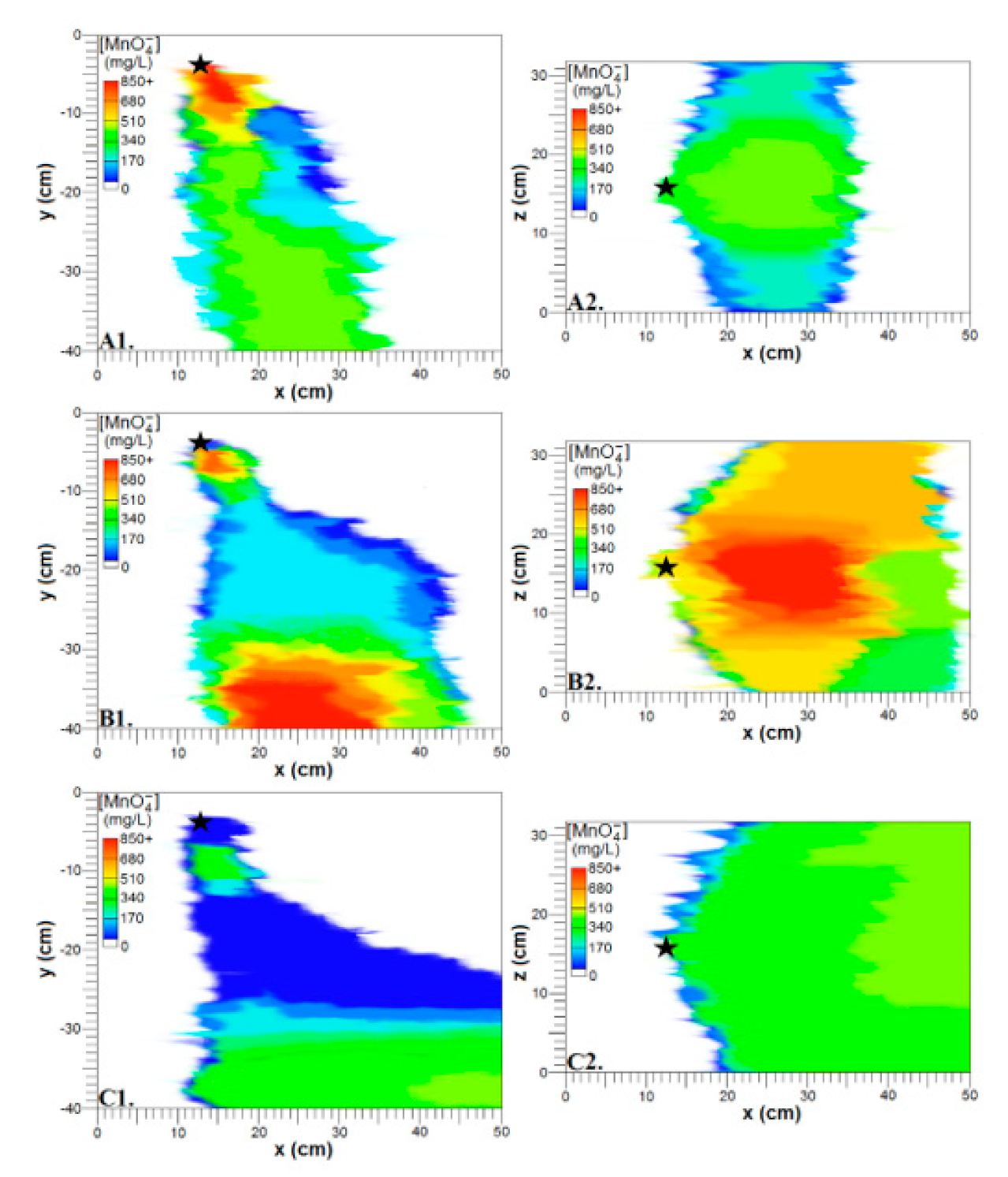
A large flow tank test with a 26 g/L N-40/B-50 mix SRPG was performed to observe the general migration and release patterns of the SRPG on a larger scale. The test showed that overall MnO4− from the SRPG sank to the bottom of the tank and demonstrated a potential for vast lateral spreading of the oxidant as depicted in Figure 7.
Approximately 18 h after injection, high concentrations of MnO4− remained localized near the injection point (Figure 7A1). This was most likely where the SRPG solution transitioned into a gel, and from it, lower concentrations diffused and sank. This resulted in relatively moderate concentrations at depths of 25 and 38 cm. Additionally, MnO4− had traveled forward ≥12 cm from the injection point and reached the farthest lateral extent permitted by the tank, 31.8 cm (Figure 7A2). Higher [MnO4−] values were localized around the central monitoring wells compared to the exterior wells, suggesting that [MnO4−] decreases with lateral dispersion.
About 54 h after injection, high concentrations of MnO4− descended to the bottom of the tank and relatively high concentrations remained near the injection point (Figure 7B1). Meanwhile, relatively low concentrations occupied the intermediate depths. Lateral spreading of the oxidant produced higher [MnO4−] values at the exterior monitoring wells which is indicative of a capability to disperse much farther laterally than the tank permitted (Figure 7B2).
Seven days after injection, [MnO4−] values had dropped significantly. Moderate concentrations resided deeper in the tank and near the injection point while low concentrations remained at intermediate depths (Figure 7C1). Lateral spreading of MnO4− at this time was relatively uniform, with moderate concentrations contacting each monitoring well past the injection point (Figure 7C2).
5. Conclusions
Depending on situational demands, either the 40 wt.% or 50 wt.% CS would make an effective gelling agent for the SRPG solution. SRPGs with a lower silica concentration may be preferred for their ability to hold greater amounts of KMnO4 while still achieving significant gelation lag times in saturated media and for their slow gelation outside of media which makes low-pressure injection of high volumes of solution easier. However, 50 wt.% CS SRPGs such as the B-50 were found to be more advantageous due to their significantly longer release durations and resistance to dilution.
Flow tank tests demonstrated that regardless of silica wt.% or type of media, the addition of CS to a KMnO4 solution enhanced lateral dispersion of the oxidant and mediated release to prolong the release duration. Contrary to some of the literature [9,10,11], counter-diffusion of MnO4− from a clay lens was not observed due to consumption of the small amount of MnO4− by NOD of the clay lens. The release duration of the SRPG was lowered from 9.2 d to 4.6 d in porous media with a clay lens. When the clay lens was fractured, the larger surface area contributed to greater MnO4− consumption, reducing the release duration to 38 h. Once the NOD of clay is met, however, the low-permeability media may contribute to prolonged release.
While the SRPG reached well beyond the benchmark release rate ≥850 μg/d, the high release of MnO4− and inability to achieve a gel lag time ≥3 d prevented a release duration ≥ 3 wk from being met. Although a desirable SRPG could not be produced in the time allotted for this study, much was learned about the behavior of different CS solutions as gelling agents, the release characteristics of the SRPG vs. pure KMnO4 solution, and the effects of different media types on the SRPG. If more control can be exercised on the gelation and high release of MnO4−, the SRPG can serve as a novel treatment option for dilute or widespread DNAPL plumes. The increased lateral dispersion of the oxidant should facilitate mixing between MnO4− and the contaminant and reduce the number of injection wells needed for remediation. Results of this study warrant further investigations focused on assessing the remedial efficiency of the SRPG through more detailed and large-scale flow tank experiments and field applications and developing a numerical model to simulate the gelation, migration, and release patterns of the SRPG solution in heterogeneous saturated porous media. The boundaries of the flow tanks and small number of concentration data in this study did not permit full lateral dispersion of the oxidant, so more research dedicated to observing the migration of the SRPG in a larger space and deriving a dispersion coefficient is warranted.
Author Contributions
Methodology, Investigation, and Writing—Original Draft Preparation, J.L.H.; Conceptualization, Writing—Review & Editing, Supervision, and Project Administration, E.S.L. All authors have read and agreed to the published version of the manuscript.
Funding
This study was partially supported by SERDP program of US Department of Defense.
Institutional Review Board Statement
Not applicable.
Informed Consent Statement
Not applicable.
Data Availability Statement
Not applicable.
Conflicts of Interest
The authors declare no conflict of interest.
References
- US EPA. Contaminated Site Clean-Up Information: Dense Nonaqueous Phase Liquids (DNAPLs). 2013. Available online: http://www.clu-in.org/contaminantfocus/default.focus/sec/Dense_Nonaqueous_Phase_Liquids(DNAPLs)/cat/Overview/ (accessed on 1 November 2013).
- Lee, E.S.; Schwartz, F.W. Characteristics and applications of controlled-release KMnO4 for groundwater remediation. Chemosphere 2007, 66, 2058–2066. [Google Scholar] [CrossRef]
- US EPA. Trichloroethylene. 2000. Available online: http://www.epa.gov/ttn/atw/hlthef/tri-ethy.html (accessed on 1 November 2013).
- Lee, B.S.; Kim, J.H.; Lee, K.C.; Kim, Y.B.; Schwartz, F.W.; Lee, E.S.; Woo, N.C.; Lee, M.K. Efficacy of controlled-release KMnO4 (CRP) for controlling dissolved TCE plume in groundwater: A large flow-tank study. Chemosphere 2009, 74, 745–750. [Google Scholar] [CrossRef] [PubMed]
- Lee, E.S.; Liu, G.; Schwartz, F.W.; Kim, Y.; Ibaraki, M. Model-based evaluation of controlled-release systems in the remediation of dissolved plumes in groundwater. Chemosphere 2008, 72, 165–173. [Google Scholar] [CrossRef] [PubMed]
- Lee, E.S.; Seol, Y.; Fang, Y.C.; Schwartz, F.W. Destruction Efficiencies and Dynamics of Reaction Fronts Associated with the Permanganate Oxidation of Trichloroethylene. Environ. Sci. Technol. 2003, 37, 2540–2546. [Google Scholar] [CrossRef] [PubMed]
- Lee, E.S.; Gupta, N. Development and characterization of colloidal silica-based slow-release permanganate gel (SRP-G): Laboratory investigations. Chemosphere 2014, 109, 195–201. [Google Scholar] [CrossRef] [PubMed]
- Iler, R.K. Chemistry of Silica: Solubility, Polymerization, Colloid and Surface Properties and Biochemistry of Silica; John Wiley and Sons Inc.: New York, NY, USA, 1979. [Google Scholar]
- Tatti, F.; Papini, M.P.; Sappa, G.; Raboni, M.; Arjmand, F.; Viotti, P. Contaminant back-diffusion from low-permeability layers as affected by groundwater velocity: A laboratory investigation by box model and image analysis. Sci. Total. Environ. 2018, 622–623, 164–171. [Google Scholar] [CrossRef]
- Schwartz, F.; Lee, E.S.; Solpuker, U.; Hawkins, J.; Cotter, Z.; Gupta, N.; Olson, P. Semi-Passive Oxidation-Based Approaches for Control of Large, Dilute Groundwater Plumes of Chlorinated Ethylenes; SERDP Project ER-1684; US Department of Defense Strategic Environmental Research and Development Program: Alexandria, VA, USA, 2014.
- Solpuker, U.; Hawkins, J.; Schincariol, R.; Ibaraki, M.; Schwartz, F.W. Harnessing the complex behavior of ultra-dense and viscous treatment fluids as a strategy for aquifer remediation. Models-Repos. Knowl. 2012, 355, 267–272. [Google Scholar]
- Siegrist, R. In Situ Chemical Oxidation Using Potassium Permanganate; DOE/EM-0496; US Department of Energy Office of Science and Technology: Washington, DC, USA, 1999; p. 24.
- Lee, E.S.; Olson, P.R.; Gupta, N.; Solpuker, U.; Schwartz, F.W.; Kim, Y. Permanganate gel (PG) for groundwater remediation: Compatibility, gelation, and release characteristics. Chemosphere 2013, 97, 140–145. [Google Scholar] [CrossRef] [PubMed]
- Yan, Y.E.; Schwartz, F.W. Kinetics and Mechanisms for TCE Oxidation by Permanganate. Environ. Sci. Technol. 2000, 34, 2535–2541. [Google Scholar] [CrossRef]
- Huling, S.G.; Pivetz, B.E. In-Situ Chemical Oxidation. United States. 2006. Available online: http://www.epa.gov/ada/gw/pdfs/insituchemicaloxidation_engineering_issue.pdf (accessed on 1 March 2015).
- Gallagher, P.M.; Pamuk, A.; Abdoun, T. Stabilization of Liquefiable Soils Using Colloidal Silica Grout. J. Mater. Civ. Eng. 2007, 19, 33–40. [Google Scholar] [CrossRef]
- Gallagher, P.M.; Lin, Y. Colloidal Silica Transport through Liquefiable Porous Media. J. Geotech. Geoenviron. Eng. 2009, 135, 1702–1712. [Google Scholar] [CrossRef]
- Persoff, P.; Apps, J.; Moridis, G.; Whang, J.M. Effect of Dilution and Contaminants on Sand Grouted with Colloidal Silica. J. Geotech. Geoenviron. Eng. 1999, 125, 461–469. [Google Scholar] [CrossRef] [Green Version]
- Zaccone, A.; Crassous, J.J.; Ballauff, M. Colloidal gelation with variable attraction energy. J. Chem. Phys. 2013, 138, 104908. [Google Scholar] [CrossRef] [PubMed] [Green Version]
- Grace. L-40, L-50, and Ludox CL-X, [Certificate of Analysis]. 2014.
- Nalco Company. Nalco MSDS and Product Bulletin Search. 2013. Available online: http://www.nalco.com/msds.htm (accessed on 1 August 2014).
- Wesbond Corporation. Wesbond Corporation. 2009. Available online: http://wesbond.com/default.htm (accessed on 1 August 2014).
- Du Pont Data Sheet: Ludox Colloidal Silica. (n.d.). Available online: http://legacy.library.ucsf.edu/documentStore/s/t/c/stc76b00/Sstc76b00.pdf (accessed on 1 August 2014).
- Park, S.; Lee, H.-B. Effect of pH on monolayer properties of colloidal silica particles at the air/water interface. Colloid Polym. Sci. 2011, 290, 445–455. [Google Scholar] [CrossRef]
- Mundle, K.; Reynolds, D.A.; West, M.R.; Kueper, B.H. Concentration Rebound Following In Situ Chemical Oxidation in Fractured Clay. Ground Water 2007, 45, 692–702. [Google Scholar] [CrossRef] [PubMed]
- Marshall, M.H.M.; McKelvie, J.R.; Simpson, A.J.; Simpson, M.J. Characterization of natural organic matter in bentonite clays for potential use in deep geological repositories for used nuclear fuel. Appl. Geochem. 2015, 54, 43–53. [Google Scholar] [CrossRef]
- Hønning, J.; Broholm, M.M.; Bjerg, P.L. Quantification of potassium permanganate consumption and PCE oxidation in subsurface materials. J. Contam. Hydrol. 2007, 90, 221–239. [Google Scholar] [CrossRef] [PubMed]
Figure 1.
Schematics of the set-up for flow tank experiments with monitoring well (MW) and injection well (IW) locations. Note: Not drawn to scale. (A1) Aerial view of small flow tank. (A2) Cross-sectional view of small flow tank with clay lens and sampling locations at varying depths. (B1) Aerial view of large flow tank. (B2) Cross-sectional view of large flow tank with sampling locations at varying depths.

Figure 2.
Gelation lag time as a function of KMnO4 concentration in batch tests from (A) Bindzil 1440, Nalco 1142, Bindzil 1440/Bindzil 9950 mix, and Nalco 1142/Bindzil 9950 SRPGs and (B) Ludox TM-40, Bindzil 9950, Ludox TM-50, and Megasol S50 SRPGs.
Figure 2.
Gelation lag time as a function of KMnO4 concentration in batch tests from (A) Bindzil 1440, Nalco 1142, Bindzil 1440/Bindzil 9950 mix, and Nalco 1142/Bindzil 9950 SRPGs and (B) Ludox TM-40, Bindzil 9950, Ludox TM-50, and Megasol S50 SRPGs.

Figure 3.
Gelation lag time results from column flow-through tests for Bindzil 1440, Bindzil 9950, Nalco 1142/Bindzil 9950 mix, Nalco 1142, and Ludox TM-40 SRPGs.
Figure 3.
Gelation lag time results from column flow-through tests for Bindzil 1440, Bindzil 9950, Nalco 1142/Bindzil 9950 mix, Nalco 1142, and Ludox TM-40 SRPGs.

Figure 4.
Release duration of (A) B-40 SRPG solutions and (B) B-50 SRPG solutions as a function of KMnO4 concentration.
Figure 4.
Release duration of (A) B-40 SRPG solutions and (B) B-50 SRPG solutions as a function of KMnO4 concentration.

Figure 5.
Optical data from flow tank tests of (A) a 26 g/L KMnO4 solution 9 h after injection and (B) a B-40 SRPG solution 73 h after injection in all-porous media.
Figure 5.
Optical data from flow tank tests of (A) a 26 g/L KMnO4 solution 9 h after injection and (B) a B-40 SRPG solution 73 h after injection in all-porous media.

Figure 6.
Mean measurements of MnO4− concentration over time from 26 g/L (A) KMnO4 solution in all-porous media, (B) B-40 SRPG in all-porous media, (C) KMnO4 solution in porous media with a clay lens, (D) B-40 SRPG in porous media with a clay lens, and (E) B-40 SRPG in porous media with a fractured clay lens. The terms “left” and “right” were used to differentiate the exterior wells based on the direction of the injection well facing the monitoring wells.

Figure 7.
Estimation of MnO4− migration. (A1) Extent of sinking and forward migration based on [MnO4−] measurements from central monitoring wells; (A2) Extent of lateral dispersion and forward migration based on [MnO4−] from wells at a depth of 38 cm 18 h after injection; (B1) Extent of sinking; (B2) Lateral dispersion, and migration 54 h after injection; (C1) Extent of sinking; (C2) Lateral dispersion, and migration 7 d after injection. Maps were created in Corel Paintshop Pro X7 by matching well measurements to their respective locations and estimating [MnO4−] in the space between wells (★ = Injection point).


| Bindzil 1440 | Nalco 1142 | Ludox TM-40 | |
| Specific gravity | 1.3 | 1.3 | 1.3 |
| Avg. particle diameter | 14 nm | 8 nm | 22 nm |
| Silica concentration | 40 wt.% | 40 wt.% | 40 wt.% |
| Measured pH at 25 °C | 9.97 | 9.66 | 8.82 |
| Viscosity at 25 °C | 15 cP | >20 cP | 5.8 cP |
| Bindzil 9950 | Megasol S50 | Ludox TM-50 | |
| Specific gravity | 1.4 | 1.4 | 1.4 |
| Avg. particle diameter | 100 nm | 70 nm | 22 nm |
| Silica concentration | 50 wt.% | 50 wt.% | 50 wt.% |
| Measured pH at 25 °C | 9.08 | 9.11 | 8.76 |
| Viscosity at 25 °C | 15 cP | 15 cP | 33.5 cP |
Table 2.
Maximum gelation lag times and corresponding release durations for each type of SRPG.
| CS Type | [KMnO4] (g/L) | Max Lag Time (h) | Release Duration (d) |
|---|---|---|---|
| B-40 | 22.9 | 5 | 2 |
| B-50 | 5.6 | 4 | 4 |
| N-40/B-50 mix | 19.0 | 4 | 4 |
| N-40 | 20.4 | 3 | 1 |
Publisher’s Note: MDPI stays neutral with regard to jurisdictional claims in published maps and institutional affiliations. |
© 2021 by the authors. Licensee MDPI, Basel, Switzerland. This article is an open access article distributed under the terms and conditions of the Creative Commons Attribution (CC BY) license (http://creativecommons.org/licenses/by/4.0/).
Share and Cite
MDPI and ACS Style
Hastings, J.L.; Lee, E.S. Optimization and Analysis of a Slow-Release Permanganate Gel for Groundwater Remediation in Porous and Low-Permeability Media. Water 2021, 13, 755. https://doi.org/10.3390/w13060755
AMA Style
Hastings JL, Lee ES. Optimization and Analysis of a Slow-Release Permanganate Gel for Groundwater Remediation in Porous and Low-Permeability Media. Water. 2021; 13(6):755. https://doi.org/10.3390/w13060755
Chicago/Turabian StyleHastings, Jesse L., and Eung Seok Lee. 2021. "Optimization and Analysis of a Slow-Release Permanganate Gel for Groundwater Remediation in Porous and Low-Permeability Media" Water 13, no. 6: 755. https://doi.org/10.3390/w13060755
Note that from the first issue of 2016, this journal uses article numbers instead of page numbers. See further details here.