
Air Diffusion and Velocity Characteristics of Self-Aerated Developing Region in Flat Chute Flows

1
China Energy Dadu River Hydropower Development Co., Ltd., Chengdu 610065, China
2
State Key Laboratory of Hydraulics and Mountain River Engineering, Sichuan University, Chengdu 610065, China
*
Author to whom correspondence should be addressed.
Water 2021, 13(6), 840; https://doi.org/10.3390/w13060840
Submission received: 14 February 2021
/
Revised: 9 March 2021
/
Accepted: 10 March 2021
/
Published: 19 March 2021
(This article belongs to the Special Issue Gas-Liquid Two-Phase Flow in the Pipe or Channel)
Abstract
:Self-aerated flows in flat chutes are encountered downstream of the bottom outlet, in spillways with a small slope and in storm waterways. In the present study, the development of self-aeration in flat chute flow is described and new experiments are performed in a long flat chute with a pressure outlet for different flow discharge rates. The distribution of air concentration, time mean velocity and velocity fluctuation in flow direction in the self-aerated developing region—where air bubbles do not diffuse next to the channel bottom—were measured and analyzed. The region of self-aeration from free surface was about 27.16% to 51.85% of the water depth in the present study. The analysis results revealed that the maximum distance of air bubble diffusion to the channel bottom increased with the development of self-aeration along the flow direction. This indicates that for flat chute flow, the process of air bubble diffusion from free surface to channel bottom was relatively long. Cross-section velocities increased along the flow direction in the self-aerated developing region, and this trend was much more remarkable in the area near water free surface. The velocity fluctuations in flow direction in cross-sections flattened and increased with the development of self-aerated flow. Higher velocity fluctuations in flow direction corresponded to the presence of much stronger turbulence, which enhanced air bubble diffusion from the water free surface to channel bottom along the flow direction.
1. Introduction
Free surface self-aeration is frequently observed in steep rivers, spillways and flat chutes, such as tunnel spillways, partially filled pipes and high-speed flow in open channels connecting to a pressure outlet in bottom outlet tunnels. The air entrainment induces a drastic change in the fluid characteristics. First, the amount of bulking caused by the entrained air makes the water depth higher than that of nonaerated water flow [1]. Aeration can eliminate or minimize cavitation damage caused by high-velocity flow in spillways, chutes and channels [2]. Studies have shown that the presence of air within the boundary layer can reduce the shear stress between the flow layers [3,4]. More recently, highly aerated flow has been recognized for its gas transfer characteristics with the transfer of atmospheric gases into the water and the volatilization of pollutants [5].
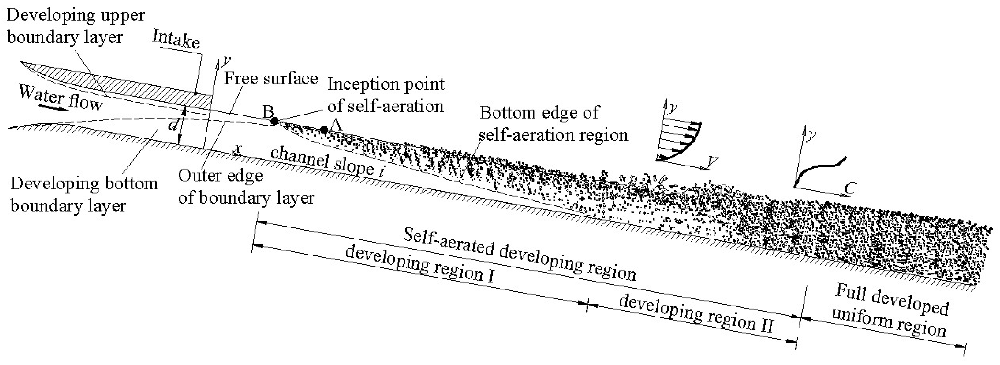
For an open channel flow in a flat chute with a pressure outlet, at the upstream end of the channel, a turbulent boundary layer which is generated by the channel bottom develops along the channel. The boundary layer thickness δ has been studied by many researchers [6,7,8]. The data of Schwarz and Cosart [9] suggested that δ/d ~ 0.18 next to the intake, where d is the approaching flow depth. Chanson [10] showed that boundary layer thickness is δ ~ x0.8 on a smooth plate, where x is the streamwise distance from the outlet. Previous studies have shown that the position of the intersection (point A in Figure 1) between the water free surface and the outer edge of the turbulent boundary layer happens at a short distance from the intake. When the turbulence acting next to the free surface is great enough to overcome the surface tension effect and buoyancy, air bubble entrainment occurs. Chanson [11] stated that the normal turbulent velocities at the surface should be larger than 0.1 to 0.3 m/s for air bubble entrainment. For a high-velocity flow discharging into a flat chute, as in the experiments of Arreguin and Echavez [12], Anwar [13] indicated that the inception point of self-aeration (point B in Figure 1), where the location of the “white water” apparition appears, is closer to the upstream end than to the intersection of the boundary layer edge with the free surface.
This means that the classical “boundary layer growth” theory for the steep slope trend, i.e., that the convergence of the inception point with the boundary layer and free surface intersection, does not apply to the inception of self-aeration in flat chutes. The flow separation and developing upper boundary layer need to be taken into consideration. The first part of the two-phase air–water flow is the self-aerated developing region, which forms before the flow gets to uniform equilibrium, and the second is the fully developed uniform region, where the turbulence diffusion is normal to the bottom and counterbalances exactly the buoyancy effect, and thus the air concentration is independent of the flow direction along the channel. In the self-aerated developing region, air bubble entrainment develops and diffuses to the maximum depth; this area along the channel is seen as developing region I. In this region, there are mainly three areas, that is, individual water drops in air, individual air bubbles in the water and clear water. For the area of individual water drops in the air, the most significant effects are on the water depth of aerated flow [14,15,16]. The transition section between individual water drops in the air and individual air bubbles is usually seen as the water depth of aerated flow increases. This section is also where the maximum gradient of air concentration from normal to the channel bottom appears [17]. Downstream of the developing region I, the air concentration distribution gradually varies along the channel, with more air bubbles entrained into the water flow and diffusing to the bottom. This distance in air–water flow can be recognized as developing region II.
A large amount of data about the self-aerated developing region II and the fully developed uniform region are available to predict the air–water flow properties of supercritical flows [18,19,20]. There is, however, little information on the self-aerated developing region I in flat chute flows, especially about the diffusing process of air bubbles to the bottom in developing region I (i.e., the area of individual air bubbles in water). In this paper, experimental data about the air concentration, time mean velocity and velocity fluctuation are obtained using a flat chute with a pressure outlet, and these characteristics of air–water flow are analyzed to further understand the process of self-aeration in high-velocity open channel flow.
2. Experimental Apparatus
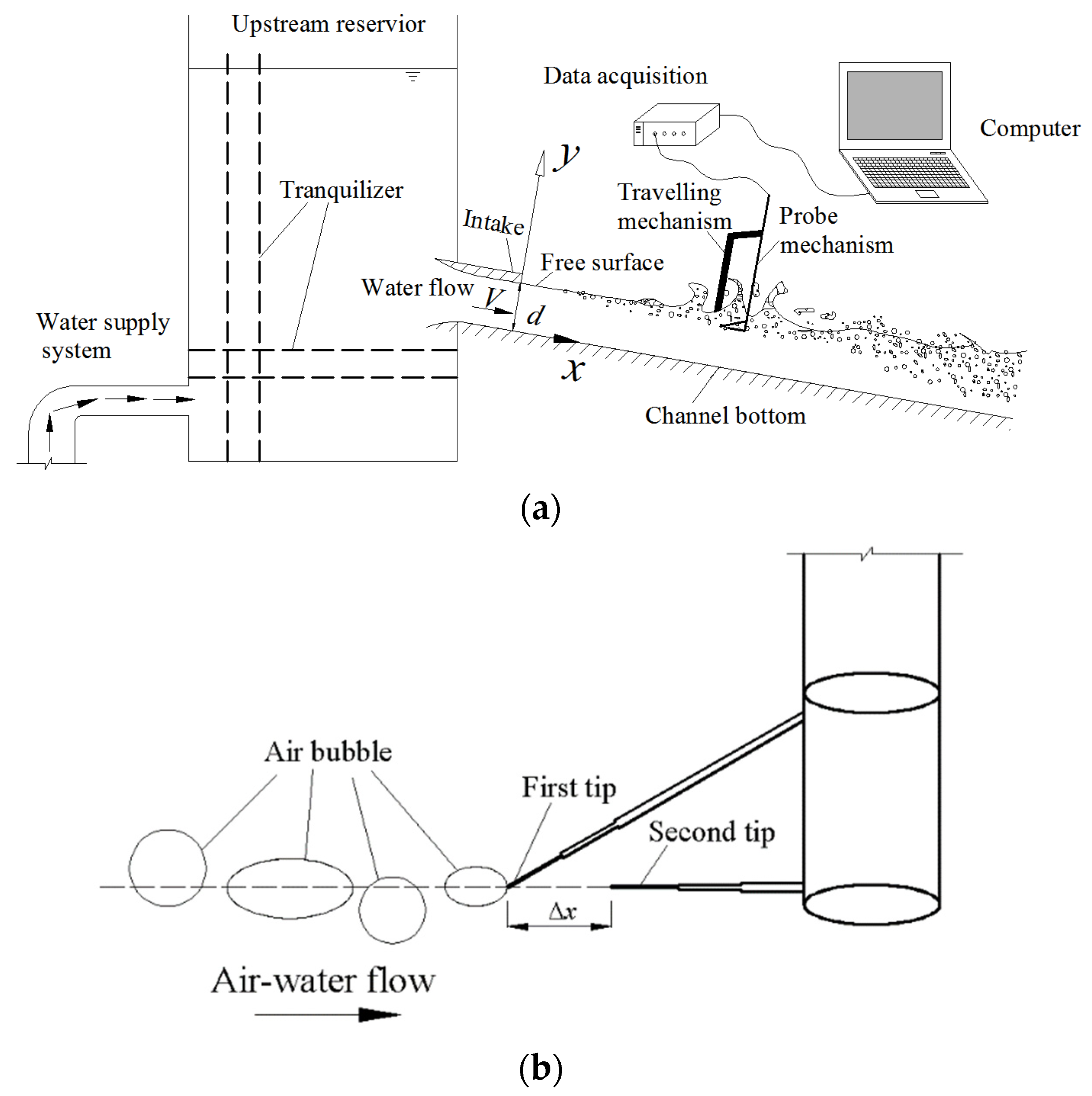
The experiments were conducted in the state key lab of hydraulics and mountain river engineering, Sichuan University. The flume was 12 m long and 0.4 m wide with a 10 degree slope. The flume was made of planed synthetic glass boards (the roughness is 0.01 mm). Flow to the flume was fed through a smooth convergent nozzle (1.5 m long), as shown in Figure 2. The nozzle exit was 80 mm high. The flow discharge was delivered by a pump connected to a closed-circuit water supply system, and a thin-plate weir was set downstream to enable an accurate discharge adjustment. Air concentration and velocity measurements were performed on the channel centerline at regular intervals along the channel, and the first cross-section measurement was 2.7 m to the pressure outlet. For high-velocity air–water flow, an intrusive phase detection probe was the most reliable instrument for air–water property measurement [21]. The principle of electrical probes is the difference in electrical resistivity between air and water, and this can give accurate information on the local air–water fluctuations. In the present study, air bubble property and air–water velocity were recorded using the CQY—Z8a measurement instrument (made by Huaihe River Water Institution, Bengbu, China), a double-tip conductivity probe. The probe consisted of two identical tips with an internal concentric electrode made of platinum with a 0.04 mm diameter and an external stainless-steel electrode with a 0.7 mm diameter. Air–water velocity measurement was based on two successive detections of air–water interfaces by the two tips, and the computation was according to a cross-correlation technique between the two tip signals [22].
The two tips were aligned in the flow direction, and the distance between the two tips was Δx = 10 mm. The cross-correlation function between the two tip signals was the maximum value of the cross-correlation coefficient R for the average time Tm taken for an “air bubble” interface to travel from the first tip to the second tip. The velocity was deduced from the time delay between the two tip signals and the two tip separation distance, Δx.
This electronic system was designed with a response time of less than 10 μs. At each position, the two tip signals from the conductivity probe were recorded with a scan rate of 100 kHz per channel for a 5 s scan period.
Clear water velocities were measured with a Pitot tube (4 mm external diameter), and water velocity fluctuation in flow direction was recorded by a pressure sensor (CY200 made by Chengdu Test Electronic Information, Chengdu, China; comprehensive accuracy of 0.1%) connected to the Pitot tube. The vertical translation of the probe was controlled by an adjustment travelling mechanism and the error on the vertical position of the probe was less than 0.1 mm. The experiment was repeated until sufficient and reliable data were obtained at each measurement profile. The flow discharge rates, Q, were 0.18 m3/s, 0.19 m3/s, 0.20 m3/s and 0.21 m3/s, respectively, and Reynolds number was approximately within 3 × 10⁵~4 × 10⁵.
3. Experimental Results and Discussions
3.1. Air Concentration Distribution and Development
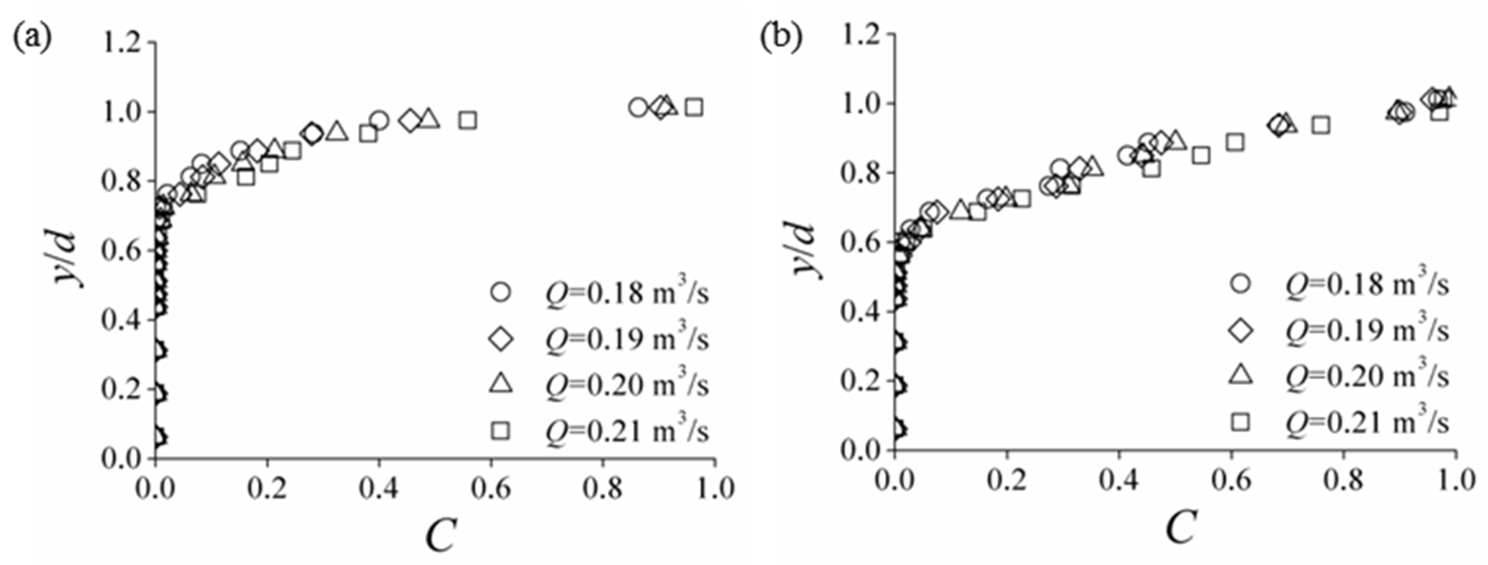
Distributions of air concentration and velocity were measured on the centerline (from x = 2.7~7.7 m). Typical results are plotted in Figure 3. Air concentration C is a function of y/d, where y is the normal distance to the channel bottom and d is the intake high. It is clear that in water flow, the air concentration increased continuously from the bottom to the free surface. At a certain cross-section, the air concentration increased much more rapidly near the water free surface, and in the self-aerated developing region, the distributions at the cross-sections are almost the same. The Froude number Fr0 = V/(gd)0.5 can be used as a flow condition for the present analysis, where V is the average flow velocity at the nozzle and g is the acceleration of gravity.
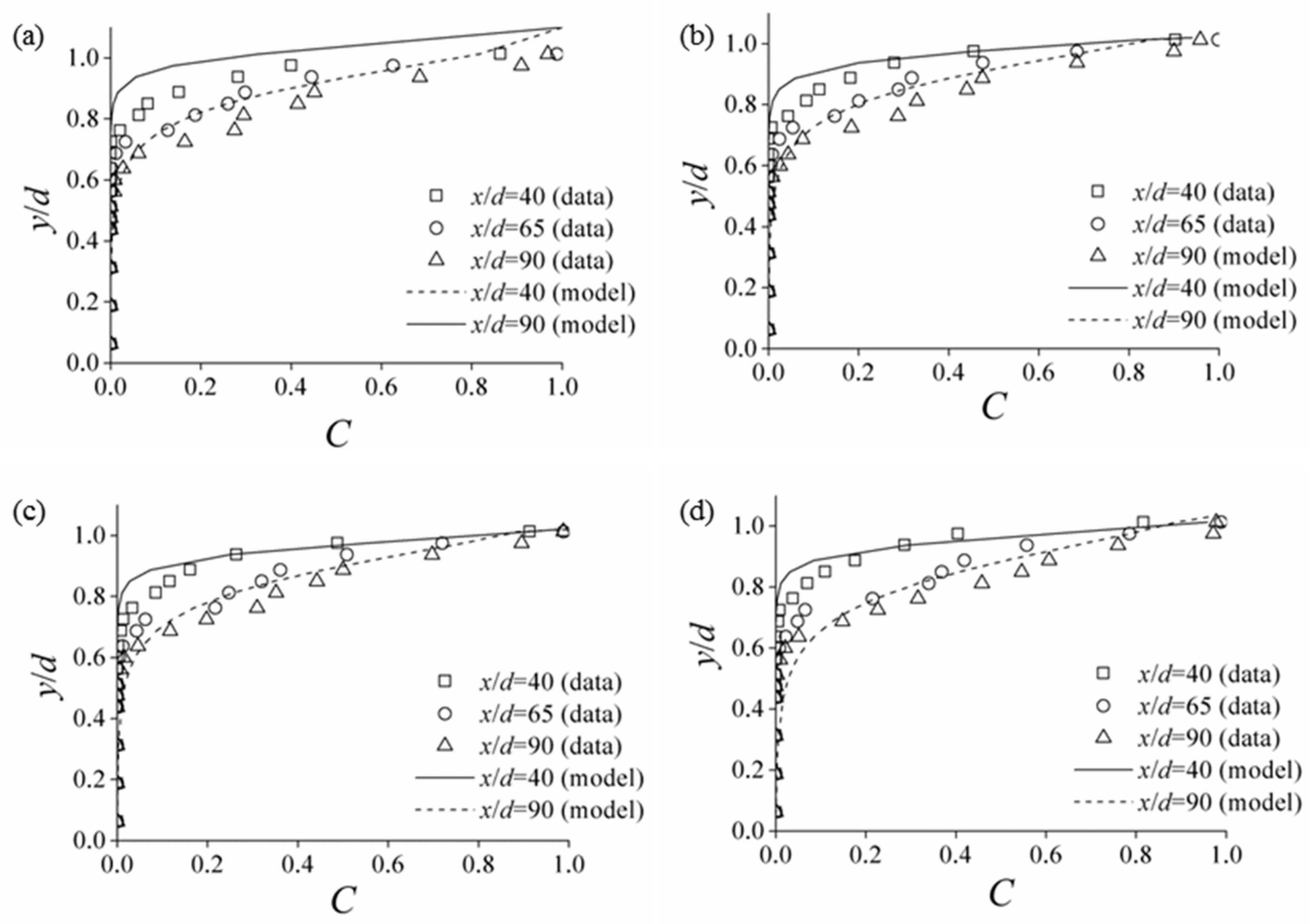
In the present work, the air concentration distributions varied gradually, and the development of air bubble diffusion was not next to the bottom wall. Figure 4 shows the comparison between the present data and the two-dimensional diffusion model [10], defined as:
where D′ and K′ are two constant parameters deduced from the mean air concentration of the cross-section. Although the distribution tendency of air concentration from the diffusion model basically fit the experimental air concentration profile, the difference in the bottom of the self-aeration region between the experimental data and the diffusion model is obvious.
Figure 5 shows the development of the self-aeration region along the flow direction, compared with the results calculated by Equation (2) and Chanson’s measured data [10]. The maximum normal distance y min of the air bubble diffusing to the channel bottom in the present study was defined as the position where no air bubble signal was obtained by the probe. In Chanson’s study, the development of air bubble diffusion at the channel bottom was relatively slower than that found in the present study. This is mainly because the channel slope of Chanson’s study was much flatter than that of the present study. The theoretical diffusion model overestimates the rate of self-aeration development in flow cross-sections. For Fr0 = 6.353, when the characteristic distance x/d increased from 33.75 to 96.25, the value of y min/d varied from 0.725 to 0.563, while in the diffusion model it varied from 0.813 to 0.313. For Fr0 = 7.412, when the characteristic distance x/d increased from 33.75 to 96.25, the value of y min/d varied from 0.688 to 0.475, while in the diffusion model, it varied from 0.850 to 0.188. In the present study, when x/d increased from 33.75 to 96.25, the region of air bubble diffusion in the flow was about 27.16% to 51.85% of the water depth (the position at y direction, where the air concentration was larger than 0.9, was approximately the water depth in the developing region of self-aeration). In Chanson’s results, the maximum difference of maximum normal distance of air bubble diffusion between experimental data and the diffusion model was at x/d = 66.67, whereas results from this study’s experimental data and the diffusion model are y min/d = 0.942 and y min/d = 0.455, respectively. The development of air bubble entrainment in self-aerated flow is complicated, especially in the self-aerated developing region. The process is affected by incoming flow conditions, the solid wall, the channel slope, and the fact that the interaction between air bubbles and water is a three-dimensional process. A more accurate description of the air bubble entrainment is needed, while paying greater attention to the development process.
3.2. Time Mean Velocity Distribution and Development
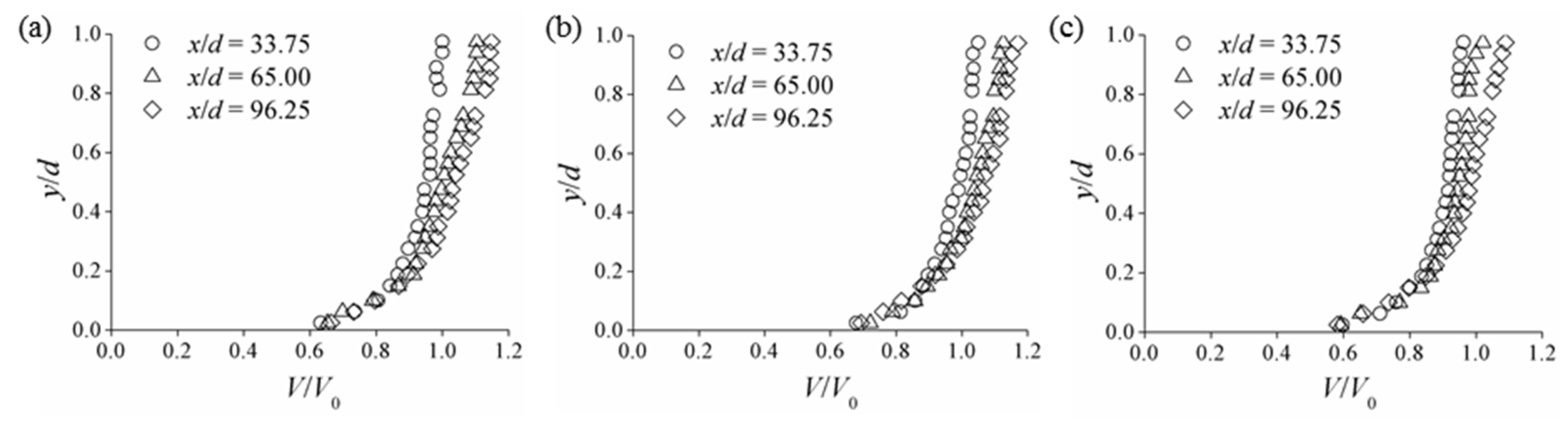
Time mean velocities in cross-sections were measured at various centerline positions from x = 2.7~7.7 m (i.e., x/d = 33.75~96.25) for different flow discharge rates. The velocity distributions at cross-sections for different flow discharge rates are plotted in Figure 6, where V0 is the mean velocity, obtained from the ratio of Q to the square of intake (0.08 × 0.4 m).
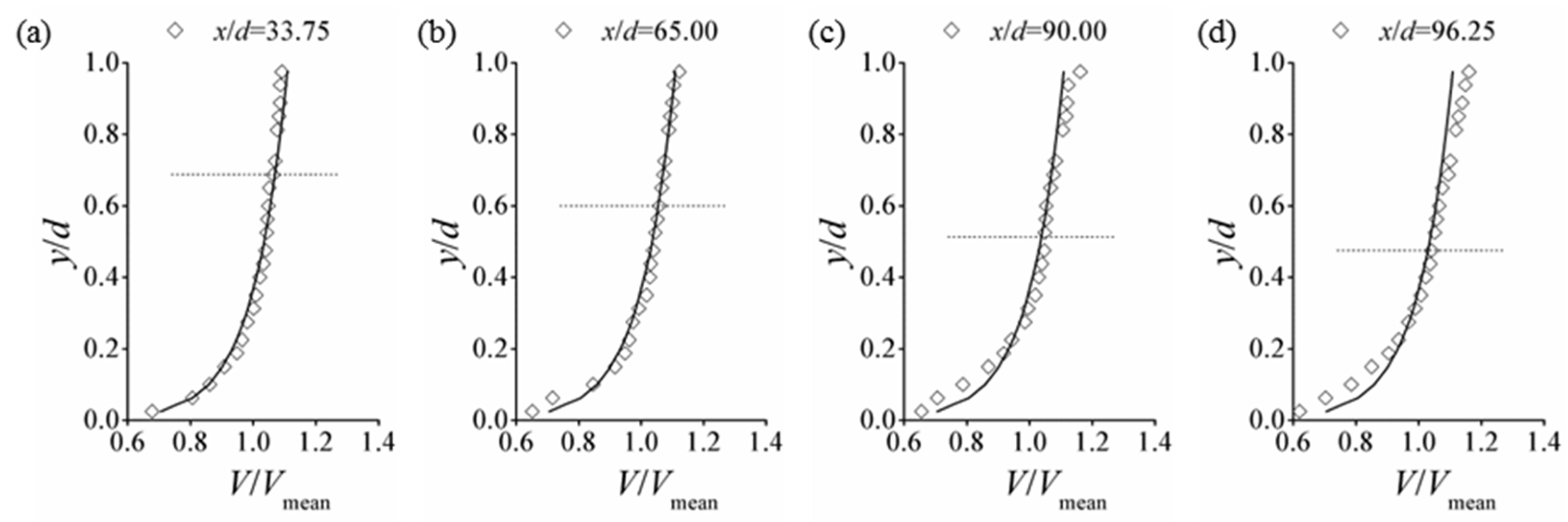
In the self-aerated developing region I, the cross-section velocities increased along the flow direction. This showed that the flow was non-uniform in self-aerated developing region I. The dimensionless velocity distributions are shown in Figure 7 and are compared with the logarithmic law for fully developed uniform flow. Vmean is the mean velocity of a certain cross-section. Considering a rough chute [23], the logarithmic law equations are:
where V* is the friction velocity, obtained with the equations:
where λ is the coefficient of friction resistance and Δ is the roughness (0.01 mm). For the cross-section near the intake (x/d = 33.75), the velocity distribution from experimental data is in good agreement with the logarithmic law. This is because the flow in intake is in the state of pressure flow, and it can be seen approximately as a uniform flow. For the cross-section near the intake in open channel flow, the air concentration was relatively low and the flow was still affected by the state of pressure uniform flow in the intake. This resulted in good agreement between the experimental data and the logarithmic law for uniform flow. With the development of flow downstream, self-aeration developed and the flow was in a state of acceleration under gravity, and this made the flow non-uniform.
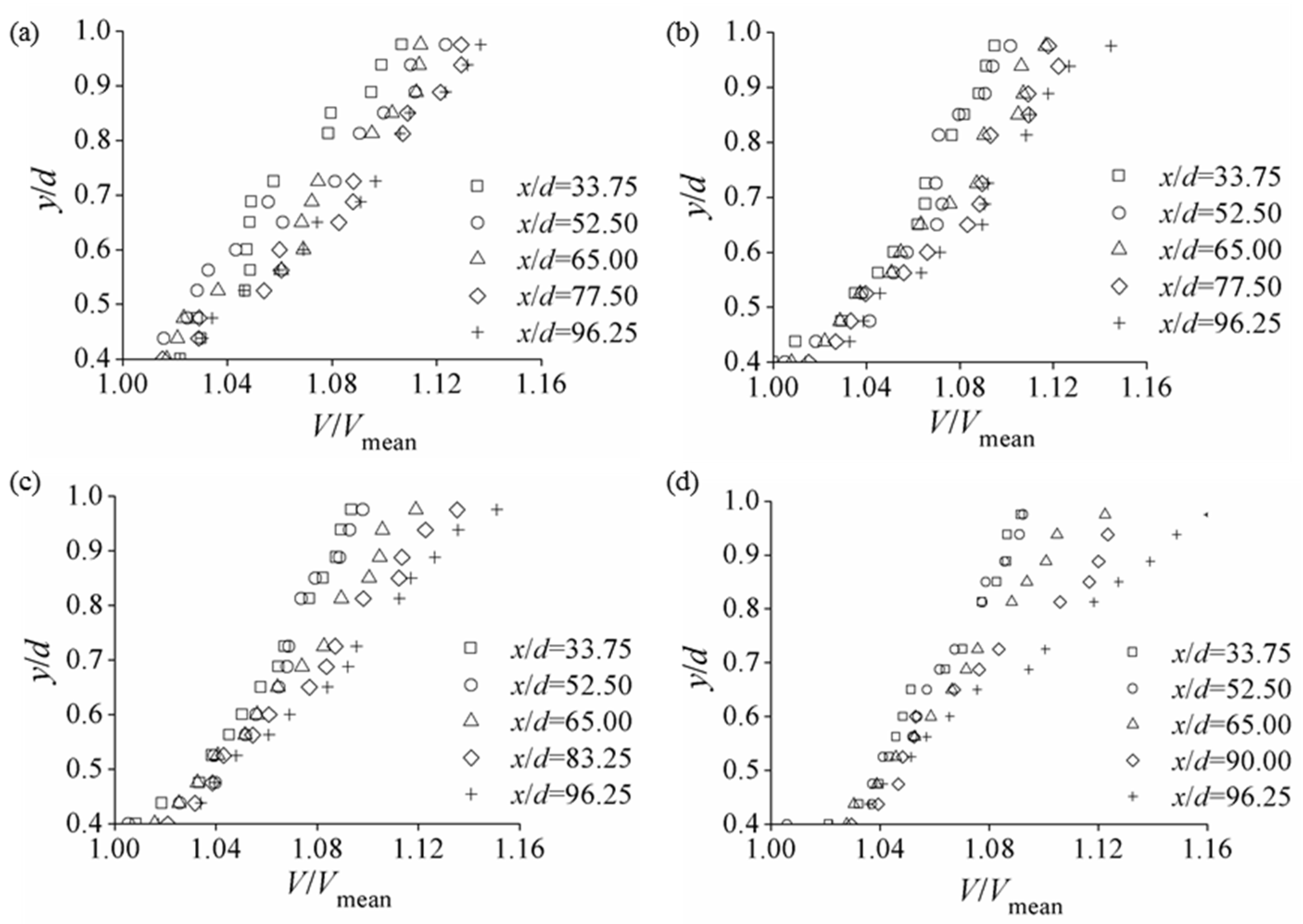
For the cross-section far from intake (x/d = 96.25), the velocities near the free surface increased as the flow developed downstream, compared with the log-law results. Considering the aeration in flow, the viscosity and shearing stress in the flow were less than those in the non-aerated flow [15]. Thus, the air–water velocity will be comparatively greater than the clear-water velocity. In the self-aerated developing region, the effect of decreased resistance on velocity was developed with air bubble diffusion into the flow. With the development of aeration in flow, resistance decreased and velocity increases in the aeration region, while it lagged in the self-aerated developing region. For a certain cross-section, the position of velocity increase in the self-aerated region was closer to the free surface of flow in the self-aerated developing region than to the maximum distance of air bubble diffusion to the channel bottom (Figure 7). Figure 8 shows the near free surface distributions of time mean velocity, and the process of resistance decrease and velocity increase in the self-aerated developing region can be seen. On the other hand, according to the property of flow movement, the water acceleration process near the channel bottom was lagged compared with the water acceleration near the free surface because of the solid surface boundary. Thus, in the self-aerated developing region, velocities of the non-uniform flow near the channel bottom still developed and were relatively smaller compared with the velocity distribution obtained from the logarithmic law for uniform flow. The difference in velocity distribution at cross-sections indicated that for the self-aerated developing region in the flat chute flow, the velocity distribution deviated from the logarithmic law for the fully developed uniform flow.
3.3. Velocity Fluctuation and Development
For self-aerated flow in the open channel, flow turbulence had a significant effect on air bubble diffusion and self-aeration development in the flow. On the channel centerline, flow fluctuations in flow direction (x direction) were measured to analyze the flow turbulence. Considering the effect of the solid surface on the measurement setup, the flow fluctuations at the transverse direction (y direction) could not be measured accurately under present conditions. Based on Kolmogorov’s hypothesis of local isotropy [24], at a sufficiently high Reynolds number, small-scale turbulent motions are statistically isotropic. In the present study, Reynolds number was within 3 × 10⁵~4 × 10⁵, and this indicated that the flow fluctuations in flow direction (x direction) could basically reflect the flow turbulence qualitatively. At a certain cross-section, the measurement range was from y/d = 0.025 to y/d = 0.725 as measured by the effects of air bubbles on the Pitot tube in the flow. The root mean square of pressure measured by transducer is given by:
where pk is the pressure recorded by the pressure transducer per signal, p0 is the mean pressure during the scanning period at each measurement point and n is the total number of pressure signals (n ≥ 1).
Figure 9 shows the dimensionless distributions of flow fluctuation σ/p0 at different cross-sections in the self-aerated developing region. The first one or two values of σ/p0 were relatively small, and this indicates that this area was affected the viscous sublayer where the flow type is mainly laminar. The viscous sublayer was caused by the solid wall of the channel bottom where the fluctuation was relatively low. With the increased distance from the channel bottom, the flow fluctuation at x direction increased rapidly, reached peak and then gradually fell. The value of σ/p0 was relatively stable near the water free surface. The distributions of flow fluctuation in flow direction similarly followed the classical “boundary layer theory”. The fluctuation in water flow developed from the channel bottom and subsequent transport to the water free surface. For a certain flow discharge rate, with increased distance to the nozzle intake (x/d = 33.75~96.25), the distribution of flow fluctuations in flow direction flattened, and the values of σ/p0 near the water free surface increased. These changes reflected flow fluctuation at x direction properties in the self-aerated developing region in the flat chute flow.
Considering the ratio of the mean flow fluctuation at x direction of each cross-section σ0 to the mean flow fluctuation at x direction of the high-velocity aerated chute flow σmean at the centerline, the ratio σ0/σmean increased along the flow direction, as shown in Figure 10. The ratio σ0/σmean showed the development process of flow fluctuation in the self-aerated developing region in the flat chute flow. With the self-aerated flat chute flow developing downstream, the fluctuation level increased. Similar trends were observed for the development of flow fluctuation at x direction in the self-aerated developing region in the present study. Considering that the flow fluctuations corresponded to the turbulence of flow, with the development of water flow downstream, the turbulence intensity increased. This increased the fluctuation enough to overcome the effects of buoyancy of air bubbles and to strengthen the air bubble diffusion inside the flow in the self-aerated developing region. Higher flow fluctuation corresponded to the presence of much stronger turbulence, which enhanced both the increased mean air concentration at the cross-section along the flow direction and the air bubble diffusion from the water free surface to the channel bottom.
4. Conclusions
New experiments were carried out to study the characteristics of the self-aerated developing region where the air bubbles do not diffuse next to the channel bottom in flat chute flows. With the flow developing downstream, air bubbles from self-aeration diffused to the channel bottom and the mean air concentration in cross-sections increased along the flow direction. The region of self-aeration from the free surface was about 27.16% to 51.85% of the water depth in the present study, and this indicated that for flat chute flow, the process of air bubble diffusion from free surface to channel bottom was relatively long. Time mean velocity and mean velocity fluctuation in flow direction in cross-section increased along the flow direction in the self-aerated developing region. In this area, the velocity fluctuation in flow direction in cross-sections flattened with the flow development downstream. In terms of turbulence, higher velocity fluctuation in flow direction corresponded to the presence of much stronger turbulence, which enhanced air bubble diffusion from the water free surface to the channel bottom and increased the mean air concentration in cross-section along the flow direction.
Author Contributions
This paper is a product of the joint efforts of the authors who worked together on the experimental model tests. J.D. has a scientific background in applied hydraulics, while L.S. and W.W. conducted the experimental data investigations. J.D. and L.S. tested the methods and wrote this paper. All authors have read and agreed to the published version of the manuscript.
Funding
Resources to cover the Article Processing Charge were provided by the National Natural Science Foundation of China (Grant No. 51939007) and Sichuan Science and Technology Program (Grant Nos. 2020YJ0320 and 2019JDTD0007).
Institutional Review Board Statement
Not applicable.
Informed Consent Statement
Not applicable.
Data Availability Statement
Not applicable.
Conflicts of Interest
The authors declare no conflict of interest.
References
- Falvey, H.T. Air-Water Flow in Hydraulic Structures; USBR Engrg Monograph, No. 41: Denver, CO, USA, 1980. [Google Scholar]
- Wood, I.R. Air Entrainment in Free-Surface Flows; IAHR Hydraulic Structures Design Manual No. 4, Hydraulic Design Considerations, A.A Balkema: Rotterdam, The Netherlands, 1991. [Google Scholar]
- Wood, I.R. Uniform region of self-aerated flow. J. Hydraul. Eng. 1983, 109, 447–461. [Google Scholar] [CrossRef]
- Chanson, H. Drag reduction in open channel flow by aeration and suspended load. J. Hydraul. Res. 1994, 32, 87–101. [Google Scholar] [CrossRef]
- Chanson, H. Predicting oxygen content downstream of weirs, spillways and waterways. Proc. ICE Water Marit. Energy 1995, 112, 20–30. [Google Scholar] [CrossRef] [Green Version]
- Schlichting, H. Boundary Layer Theory, 7 ed.; McGraw-Hill: New York, NY, USA, 1979. [Google Scholar]
- Bauer, W.J. Turbulent boundary lauer on steep slopes. Trans. Am. Soc. Civil. Eng. 1954, 119, 1212–1233. [Google Scholar] [CrossRef]
- Wang, J.Y. A study on computation of water depth in high velocity open channel flow. J. Hydraul. Eng. 1981, 5, 48–52. (In Chinese) [Google Scholar]
- Schwarz, W.H.; Cosart, W.P. The two-dimensional wall-jet. J. Fluid Mech. 1961, 10, 481–495. [Google Scholar] [CrossRef]
- Chanson, H. Air Bubble Entrainment in Free-Surface Turbulent Shear Flows. 1996. Available online: https://www.sciencedirect.com/book/9780121681104/air-bubble-entrainment-in-free-surface-turbulent-shear-flows?via=ihub=#book-description (accessed on 14 March 2021).
- Chanson, H. Self-Aerated Flows on Chutes and Spillways. J. Hydraul. Eng. 1993, 119, 220–243. [Google Scholar] [CrossRef] [Green Version]
- Arreguin, F.; Echavez, G. Natural Air Entrainment in High Velocity Flows. In Proceedings of the Conference on Advancements in Aerodynamics, Fluid Mechanics and Hydraulics, Minneapolis, MN, USA, 3–6 June 1986; Available online: https://cedb.asce.org/CEDBsearch/record.jsp?dockey=0048614 (accessed on 14 March 2021).
- Anwar, H.O. Self-aerated flows on chutes and spillways-discussion. J. Hydraul. Eng. 1994, 120, 778–779. [Google Scholar] [CrossRef]
- Morris, H.M. Applied Hydraulics in Engineering; Throndald Press Company: London, UK, 1963. [Google Scholar]
- Wu, C.G. A research on self-aerated flow in open channels. J. Hydroelectric Eng. 1988, 4, 23–36. (In Chinese) [Google Scholar]
- Afshar, N.R.; Asawa, G.L.; Raju, K.G.R. Air concentration distribution in self-aerated flow. J. Hydraul. Res. 1994, 32, 623–631. [Google Scholar] [CrossRef]
- Straub, L.G.; Anderson, A.G. Experiments on Self-Aerated Flow in Open Channels. J. Hydraul. Div. 1958, 84, 1–35. [Google Scholar] [CrossRef]
- Chanson, H. Uniform aerated chute flow-discussion. J. Hydraul. Eng. 1992, 118, 944–945. [Google Scholar] [CrossRef] [Green Version]
- Yang, Y.Q.; Wu, C.G. A study on air concentration distribution of the developing zone in self-aerated open channel flows. J. Chengdu Uni. Sci. Technol. 1992, 63, 29–34. (In Chinese) [Google Scholar]
- Bachalo, W. Experimental methods in multiphase flows. Int. J. Multiph. Flow 1994, 20, 261–295. [Google Scholar] [CrossRef]
- Toombes, L.; Chanson, H. Surface waves and roughness in self-aerated supercritical flow. Environ. Fluid Mech. 2007, 5, 259–270. [Google Scholar] [CrossRef]
- Chanson, H. Measuring air-water interface area in supercritical open channel flow. Water Res. 1997, 31, 1414–1420. [Google Scholar] [CrossRef] [Green Version]
- Wu, C.G. Hydraulics; Higher Education Press: Beijing, China, 2003. (In Chinese) [Google Scholar]
- Pope, S.B. Turbulent Flows. Meas. Sci. Technol. 2001, 12, 2020–2021. [Google Scholar] [CrossRef]
Figure 1.
The region of self-aerated developing flow.

Figure 2.
Sketch of experimental setup: (a) Schematic depiction of experimental configuration; (b) Sketch of the double-tip conductive probe.
Figure 2.
Sketch of experimental setup: (a) Schematic depiction of experimental configuration; (b) Sketch of the double-tip conductive probe.

Figure 3.
Comparison of air concentration distributions for different flow discharge rates: (a) x/d = 40; (b) x/d = 90.
Figure 3.
Comparison of air concentration distributions for different flow discharge rates: (a) x/d = 40; (b) x/d = 90.

Figure 4.
Air concentration distributions in cross-sections: (a) Fr0 = 6.353; (b) Fr0 = 6.706; (c) Fr0 = 7.059; (d) Fr0 = 7.412.
Figure 4.
Air concentration distributions in cross-sections: (a) Fr0 = 6.353; (b) Fr0 = 6.706; (c) Fr0 = 7.059; (d) Fr0 = 7.412.

Figure 5.
Comparison between experimental data and calculated results for the development of air bubble diffusion to the channel bottom.
Figure 5.
Comparison between experimental data and calculated results for the development of air bubble diffusion to the channel bottom.

Figure 6.
Velocity distributions in cross-sections along the flow direction: (a) Q = 0.18 m3/s; (b) Q = 0.19 m3/s; (c) Q = 0.21 m3/s.
Figure 6.
Velocity distributions in cross-sections along the flow direction: (a) Q = 0.18 m3/s; (b) Q = 0.19 m3/s; (c) Q = 0.21 m3/s.

Figure 7.
Mean time velocity profiles in the self-aerated developing region in chute flow for discharge rate Q = 0.21 m3/s: ◊, experimental data; solid line, the log law, Equations (3)–(5); dot-dashed line, the maximum distance of air bubble diffusion to the channel bottom at each cross-section.
Figure 7.
Mean time velocity profiles in the self-aerated developing region in chute flow for discharge rate Q = 0.21 m3/s: ◊, experimental data; solid line, the log law, Equations (3)–(5); dot-dashed line, the maximum distance of air bubble diffusion to the channel bottom at each cross-section.

Figure 8.
Near-free surface distribution of time mean velocity: (a) Q = 0.18 m3/s; (b) Q = 0.19 m3/s; (c) Q = 0.20 m3/s; (d) Q = 0.21 m3/s.
Figure 8.
Near-free surface distribution of time mean velocity: (a) Q = 0.18 m3/s; (b) Q = 0.19 m3/s; (c) Q = 0.20 m3/s; (d) Q = 0.21 m3/s.

Figure 9.
Dimensionless distributions of flow fluctuation at x direction in cross-sections: (a) Q = 0.18 m3/s; (b) Q = 0.19 m3/s; (c) Q = 0.21 m3/s.
Figure 9.
Dimensionless distributions of flow fluctuation at x direction in cross-sections: (a) Q = 0.18 m3/s; (b) Q = 0.19 m3/s; (c) Q = 0.21 m3/s.

Figure 10.
Dimensionless distributions of flow fluctuation at x direction along the flow direction.

Publisher’s Note: MDPI stays neutral with regard to jurisdictional claims in published maps and institutional affiliations. |
© 2021 by the authors. Licensee MDPI, Basel, Switzerland. This article is an open access article distributed under the terms and conditions of the Creative Commons Attribution (CC BY) license (http://creativecommons.org/licenses/by/4.0/).
Share and Cite
MDPI and ACS Style
Song, L.; Deng, J.; Wei, W. Air Diffusion and Velocity Characteristics of Self-Aerated Developing Region in Flat Chute Flows. Water 2021, 13, 840. https://doi.org/10.3390/w13060840
AMA Style
Song L, Deng J, Wei W. Air Diffusion and Velocity Characteristics of Self-Aerated Developing Region in Flat Chute Flows. Water. 2021; 13(6):840. https://doi.org/10.3390/w13060840
Chicago/Turabian StyleSong, Liaochao, Jun Deng, and Wangru Wei. 2021. "Air Diffusion and Velocity Characteristics of Self-Aerated Developing Region in Flat Chute Flows" Water 13, no. 6: 840. https://doi.org/10.3390/w13060840
Note that from the first issue of 2016, this journal uses article numbers instead of page numbers. See further details here.