
Oily Wastewater Treatment: Overview of Conventional and Modern Methods, Challenges, and Future Opportunities
by
 , ,
, ,
Khaled Abuhasel
1 ,
,
Mohamed Kchaou
1,*,
Mohammed Alquraish
1,
Yamuna Munusamy
2 and
Yong Tzyy Jeng
2 1
Department of Mechanical Engineering, College of Engineering, University of Bisha, P.O. Box 001, Bisha 67714, Saudi Arabia
2
Department of Petrochemical Engineering, Faculty of Engineering and Green Technology, Universiti Tunku Abdul Rahman, Petaling Jaya 31900, Malaysia
*
Author to whom correspondence should be addressed.
Water 2021, 13(7), 980; https://doi.org/10.3390/w13070980
Submission received: 13 February 2021
/
Revised: 28 March 2021
/
Accepted: 29 March 2021
/
Published: 2 April 2021
(This article belongs to the Section Wastewater Treatment and Reuse)
Abstract
:Industrial developments in the oil and gas, petrochemical, pharmaceutical and food sector have contributed to the large production of oily wastewater worldwide. Oily wastewater pollution affects drinking water and groundwater resources, endangers aquatic life and human health, causes atmospheric pollution, and affects crop production. Several traditional and conventional methods were widely reported, and the advantages and limitations were discussed. However, with the technology innovation, new trends of coupling between techniques, use of new materials, optimization of the cleaning process, and multiphysical approach present new paths for improvement. Despite these trends of improvement and the encouraging laboratory results of modern and green methods, many challenges remain to be raised, particularly the commercialization and the global aspect of these solutions and the reliability to reduce the system’s maintenance and operational cost. In this review, the well-known oily wastewater cleaning methods and approaches are being highlighted, and the obstacles faced in the practical use of these technologies are discussed. A critical review on the technologies and future direction as the road to commercialization is also presented to persevere water resources for the benefit of mankind and all living things.
1. Introduction
Clean water and sanitation were one of the sustainable development goals (SDG) set by the United Nations General Assembly in 2015. According to the UN, water scarcity could displace 700 million people by the year 2030, and in 2017, 2.2 billion of the world’s population still lacked access to safe drinking water. Rapid urbanization and industrialization have made matters worse by the discharge of large volumes of wastewater, which needs to be treated carefully before being released to natural water bodies [1].
Wastewater from industry can contain toxic chemicals, heavy metals, microorganisms, biological substances, microplastics, oil and viruses [2]. The United Nations Educational, Scientific and Cultural Organization (UNESCO) reported that more than 80% of this wastewater is not being treated at all before being released to the water body [3]. Wastewater treatment is not being properly adopted by industries due to high wastewater treatment facility setup costs, high operational cost, large space requirement in the area near the industry, less legislative enforcement of discharge limit and less technical understanding of wastewater treatment systems. Some countries have taken a serious approach to water-saving and water pollution control. For instance, in China, a Water Pollution Control Action Plan was enforced starting January 2015, where the focus was given on water resources conservation and protection. Industry must comply with this plan by designing wastewater treatment systems to separate pollutants from water, recycle the water and reuse [4].
In the EU, reclaimed wastewater usage is included in the circular economy strategy and governed by Water Framework Directive (2000/60/EC) (WFD). WFD has led to the secondary treatment of 88% of EU wastewaters, but the reuse is still low [5]. In Latin America and the Caribbean, the World Bank, through its “Wastewater: From Waste to Resource “initiative, had created awareness among governing parties on the potential of converting wastewater to valuable resources, such as energy, reusable water, nutrients and bio-solids [6]. Oily wastewater is one of the major constituents of wastewater discharged by industry. A large volume of oily wastewater is being generated by food and beverage, but the majority of oil mixed in water is coming from petrochemical and metal processing industries, in terms of fats, hydrocarbons, and petroleum fractions like diesel oil, gasoline, and kerosene. These constituents exist in the form of oil-in-water emulsions [7]. In 2002, U.S National Research Council reported that 1.3 million tons of oil were released to the sea annually from known sources [8].
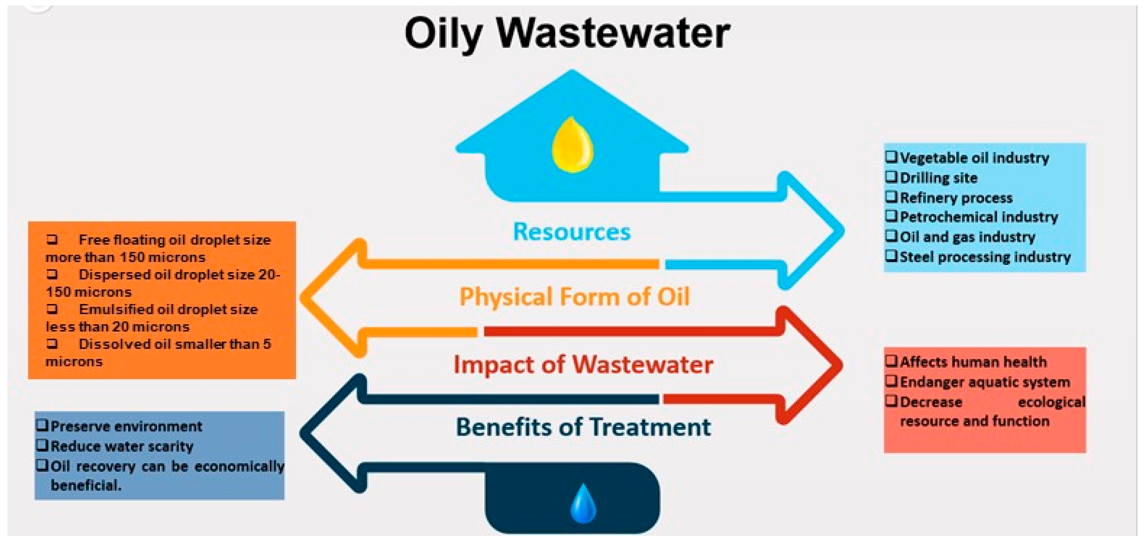
Oily wastewater is carcinogenic and mutagenic to human health and could also inhibit plant growth. Oily wastewater discharge without proper treatment can increase the biological oxygen demand (BOD) and chemical oxygen demand (COD) of the water body, reduce sunlight penetration into the water by forming a layer on the water surface and thus disrupt the aquatic ecosystem [9]. Thus, treatment of oily wastewater is crucial to reduce its effect on the environment and humans; recovery of oil from oily wastewater treatment could also provide economic benefits [10,11,12,13]. The overview of oily wastewater resources, impact and benefit of treatment are summarized in Figure 1.
Many technological advances in wastewater treatment have been achieved in the past three years from 2018 onwards. The main reasons for these achievements are the multidisciplinary approach, advancement in material science, particularly in nanomaterial and integration of technology. In this paper, a comprehensive review of the work done using conventional technologies and the advancement in modern technologies from the period of 2018 onwards are being discussed in detail. The review also includes future directions in the development of modern technologies for further commercialization. The review is expected to benefit researchers and industry to identify the gaps for practical use of oily wastewater treatment systems and lead their effort in the right direction for better output of treatment.
2. Oily Wastewater Problem
Nowadays, many industries generate a great quantity of oily wastewater, which causes various adverse impacts on the surrounding environment and sanitary conditions [14,15]. In fact, oily wastewater adversely affects our drinking water, groundwater resources, aquatic resources, human health, and crop production. Many countries are setting regulatory limits on the maximum oil concentration in oily wastewater discharge to be within the 5–100 mg/L range. Some of the region-specific limits are being listed in Table 1. Thus, the development of an effective strategy and less expensive means to treat oily wastewater is a crucial environmental need [16].
3. Traditional Methods to Clean Oily Wastewater
To clean oily wastewater, many methods are forecasted and classified into chemical, physical, mechanical and biological approaches. In the following paragraph, the principle of several methods is presented, and its viability is discussed.
3.1. Physical Methods
Gravity separation (GS) and dissolved air flotation (DAF) can be classified as physical methods to clean oily wastewater. GS system is based on the difference of density between oil and water. A great density difference between oil and water is required to promote good separation [25]. Currently, GS is being used as the first stage separation process for dispersed and floating oil, and it is not applicable for the separation of emulsified oil [26]. In the 1990s, many studies had been conducted to evaluate the effectiveness of gravity separators in oil spills, and these studies focus on the efficiency of the separators after the weathering effect on the oil spills [27], mathematical modeling of the mechanism in the separators [28] and the design of separators to warrant ease of operation for variable fluids and operating conditions [29]. GS is a very simple system, but it has many disadvantages like limited separation capacity, requires a large area for setup and complex management and operation [30,31]. Thus, not much research had been reported from 2018 to recent times on the development of this system.
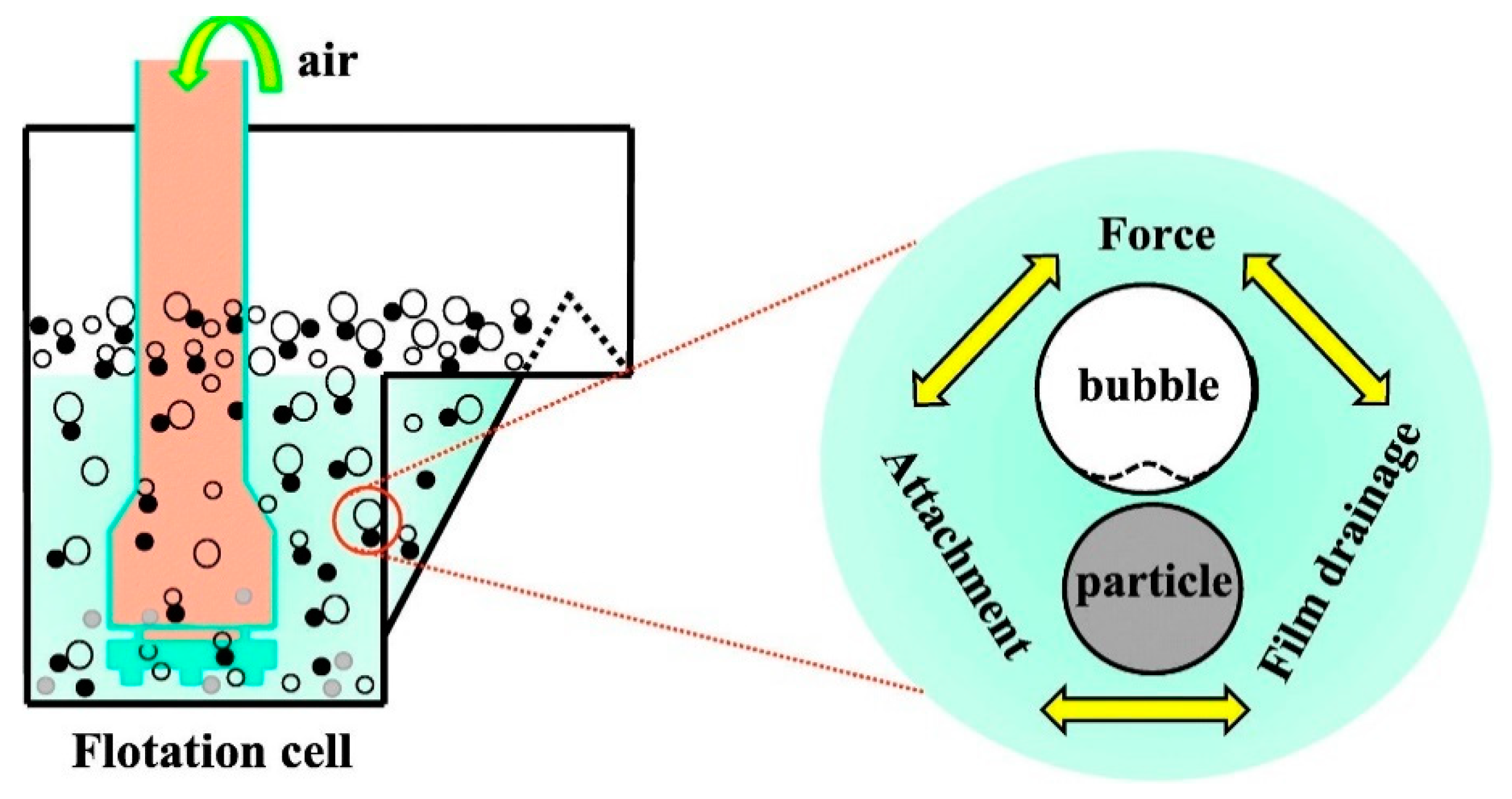
The principle of DAF is to introduce air under pressure at the bottom of an open basin, and as the air bubbles rise to the top of the basin, it will bring along pollutants. The concept of attachment of pollutants on the air bubbles is illustrated in Figure 2 [32]. Conventional DAF generates microbubbles with sizes ranging from 20–100 microns. The microbubbles stick to the oil droplets and increase the droplet’s buoyancy to move upward. In the DAF process, pressure and saturation of air in the wastewater are two important parameters to be monitored. For the microbubbles to be generated and float to the surface of the system, the pressure must be reduced to atmospheric conditions with an excess amount of dissolved gas [31].
As compared to the GS method, DAF produces treated water with higher quality because it is capable of removing emulsified oil [33]. The system operates with improved surface loading and requires smaller and shallower treatment facilities [34]. However, this method has few disadvantages, which include high operating cost due to the need to generate a constant stream of bubbles, especially when current research works reported that ultrafine bubbles are preferred due to their large surface area. This is because the size of microbubbles ranges from 20 to 100 micron, while the size of emulsified oil is 20 micron and below, thus the microbubbles cannot remove the emulsified oil efficiently. DAF with nanobubbles (NB) was developed and showed capability for more than 90% oil removal from wastewater [35]. High capital cost to construct holding tanks and purchase of pump for ultrafine bubble generation are challenges that need to be overcome by this system for practical application.
The recent trend of studies related to physical oily wastewater cleaning methods is listed in Table 2. Most of the recent works are focused on DAF system design and effort to reduce the surface tension of oil by adding a surfactant to the DAF system. These approaches had yielded more than 90% of oil separation efficiency compared to 50–60% separation efficiency in the traditional DAF system.
3.2. Chemical Methods
Flocculation and, most recently, electrochemical (ET) technologies are among the popular chemical methods employed for oily wastewater cleaning.
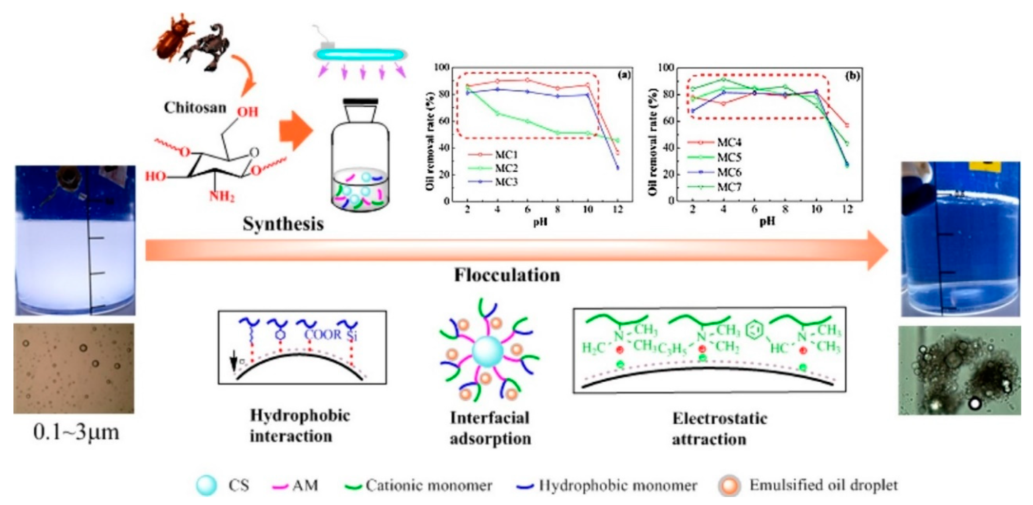
In the flocculation method, flocculants are added into wastewater to neutralize negative charges of the oil suspension or emulsion and bridge the particles together to form flocs [41]. This method is very popular in the treatment of oily wastewater from palm oil mill effluent (POME). The efficiency of this method is largely dependent on flocculants type and dosage, initial concentration of oil and the temperature and pH of the wastewater [11]. Figure 3 illustrates the flocculation mechanism of modified chitosan in the treatment of diesel containing oily wastewater.
The physical and chemical properties of flocculants play a major role in the successful separation of oil from water using this approach [43]. The common types of flocculants used in oily wastewater treatment include inorganic flocculants and organic polymeric flocculants. Compared to methods such as membrane filtration, DAF and biological technologies, flocculation is easier to operate and has lower capital and operational costs [44]. However, the main drawback of this method is related to the flocculants. The inorganic flocculants, such as aluminum sulfate, polymerized ferrous sulfate, and poly-(aluminum chloride) (PAC), are cheap and easy to use but exhibit low flocculating efficiency [45]. Adjustment of pH is required when using inorganic flocculants. Organic polymeric flocculants, such as polyacrylamide has higher flocculation ability at a lower dosage and workable in all ranges of pH, but possess health and environmental hazard due to its incapability to biodegrade [46]. Many research studies have also reported neurotoxic and neurodegeneration effects on humans when both these substances are left out in treated water [47,48]. Another major drawback of inorganic and organic polymeric flocculants is the creation of a large volume of sludge during the treatment process, which needs secondary treatment [49].
To overcome the problems related to traditional flocculants, the current trend of research is focused on the establishment of natural polymeric flocculants, such as chitosan and extracellular polymeric substances (EPS), which does not generate toxic residue and can reduce sludge formation or produce sludge that could biodegrade using microbes [50]. However, due to lack of confidence in natural flocculants and the effectiveness study is still at the initial stage, the natural flocculants are mainly used as flocculation aid together with organic polymeric flocculants.
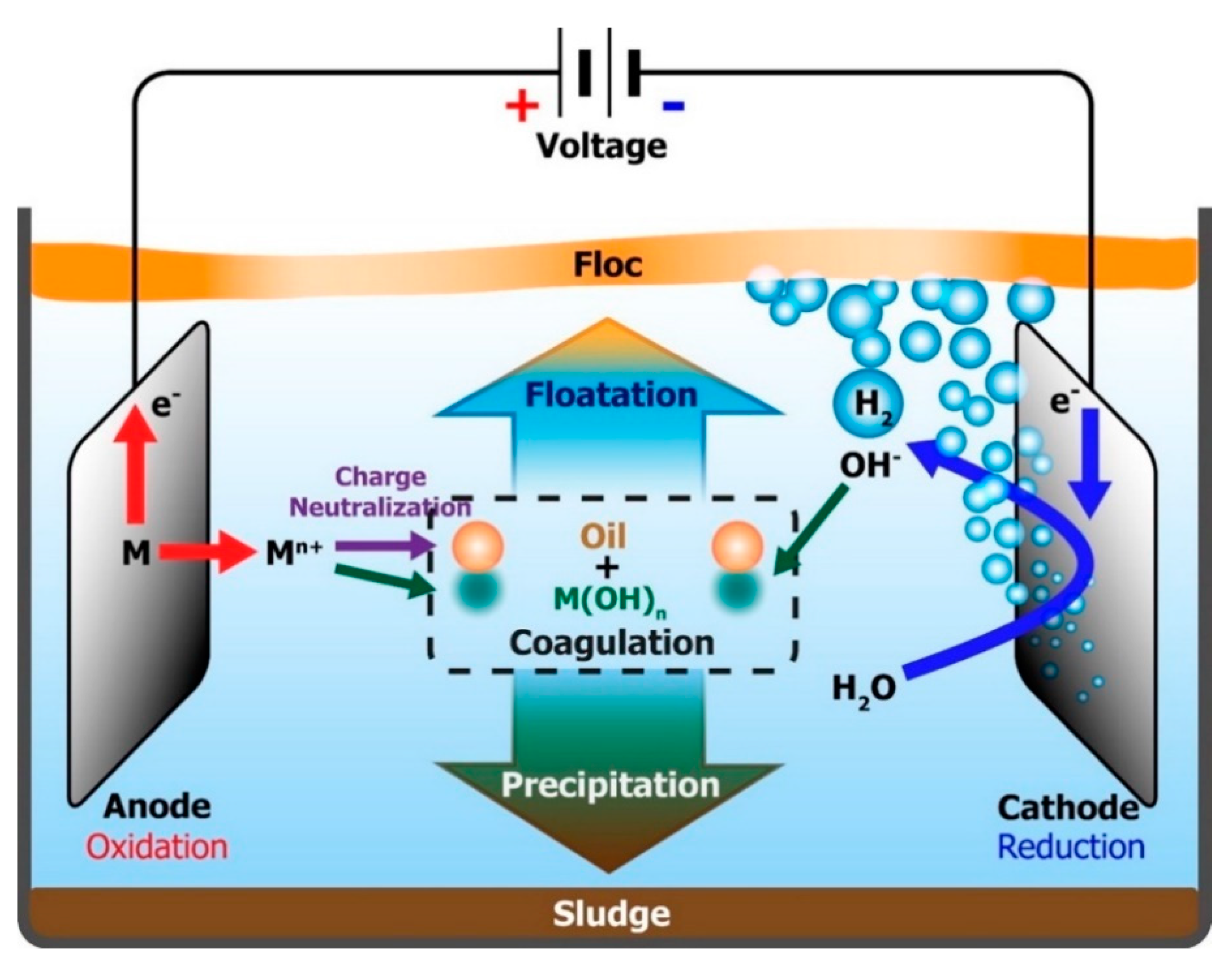
ET can be classified into systems of electroflotation, electrocoagulation and electrofloculation. These systems can be used separately, but often yield lower efficiency in oily wastewater treatment thus it is commonly combined together. All these methods involve the application of electrochemical cells, where electrodes are dipped into oily wastewater, and a determined difference of potential is being applied [51]. In the ET system, oily wastewater is treated either using electrochemical oxidation (EO) by direct anodic oxidation or indirect electro-oxidation (EIO) with strong oxidants formed during electrolysis [52]. The aim is to oxidize the oil to CO2, H2O and biodegradable byproducts [53]. Figure 4 illustrates a combination of all these three systems for oily wastewater treatment [54].
Electrofloculation and electrocoagulation are a combination of the oxidation and flocculation processes. The electrochemical cell in this system has sacrificial electrodes, which are commonly made of aluminum or iron. Through redox reaction, Al3+ or Fe3+ cations are produced by anode electrode, and these cations undergo spontaneous reaction with -OH formed by cathode to produce hydroxides and polyhydroxides. Polyhydroxides have a large surface area and act as flocculants to adsorb emulsified oils [55,56]. The flocs are then removed by floatation or sedimentation [57]. Microbubbles of H2 gas are also generated in this system, which assists the flotation of flocculated particles.
In electroflotation, oxygen and hydrogen gases are produced at the anode and cathode. These gasses form small bubbles, which can attach to oil droplets and then carry together the oil droplets to the water body’s top. The interaction between the bubbles and the oil droplet occurs in four distinct steps. First, the bubbles collide and attach themselves to the oil droplets. Then, agglomerates are formed, and more bubbles are entrapped into the agglomerates to form flocs. Finally, the flocs sweep the water body upward [58].
The main advantages of ET include versatility and energy efficiency, where the method is practical to be used in small, medium and large-scale [59,60]. Many works in the literature also reported ET to be relatively low cost, could be fully automated and require a minimum amount of chemicals [61,62]. This system’s efficiency is influenced by the electrode type, design, shape and arrangement [63], density and type of current [64] and mode of operation, either to be in batch or continuous. The major problem faced in the commercialization of this technology is the electrodes’ corrosion when the oily wastewater contains other corrosive components, such as chloride ions. Corrosion of the electrodes causes a reduction in the system efficiency over some time [65].
The latest three years’ research findings related to chemical methods are listed in Table 3. From these research works, it can be concluded that the optimum amount of oil removal through the flocculation method is around 91–92% efficiency, while in the ET system, up to 99% of oil removal efficiency could be achieved. The research in the flocculation method is mainly focused on improving the flocculant’s properties so that they can be used in a wider application window and improve the removal of flocs after treatment. At the same time, an improvement in the operating system and parameters for practical application had been extensively studied for the ET method.
3.3. Demulsification Methods
Demulsification is used to separate oil-in-water suspension and oil-in-water emulsion. Conventional demulsification can be divided into three operational stages; destabilization of the oil–water interface followed by aggregation of oil and gravitational separation [77]. Demulsification of oil in water could be executed using three approaches; physical, chemical or biological.
In the conventional chemical approach, substances such as ethylene oxide, silicone surfactant, ethylcellulose polymers and formaldehyde, are used as demulsifiers [78]. Recently, carbon-based nanomaterials, such as magnetic graphene oxide, reduced graphene oxide (rGO), and polyvinyl alcohol grafted carbon black, are being used as demulsification chemicals with oil removal efficiency reported being more than 99% within a time less than 30 min [79,80,81]. However, the major disadvantages of the chemical demulsification method are the creation of byproducts and secondary pollution [82].
In the biological approach, the microbial cell is used for demulsification. The proteins and lipids in microbial cell surface and biosurfactant produced by the cell could be used to demulsify oil at a wide range of pH, temperature and salinity [83]. The common microorganism used for this purpose is of terrestrial origin or marine microorganisms. The major disadvantages of this method are the long cultivation time of the microbes and the unstable demulsification effect [84].
Physical demulsification is carried out by separating oil and water through mechanical action, such as centrifugation or stirring. In centrifugation, the oil-in-water emulsion is separated through a difference in density. High centrifugation force and high, stirring speed are required to perform effective demulsification. The process is energy-intensive and not economical [85].
A more recent approach in demulsification is chemical emulsion breaking (CEB). CEB is mainly dependent on the adsorption of emulsified oil on chemicals. The particles used for adsorption must be able to change the physicochemical properties of the natural elastic film known as asphaltenes, which form around the stable oil emulsion in water [86]. Activated carbon is one of the most popular inorganic substances studied as an adsorbent because it has a large specific surface area and contains microspores. Yet, its application in oily wastewater treatment is limited because of weak adsorption selectivity, expensive and difficult regeneration [87].
Thus, many researchers had worked on improving the performance of adsorbents, such as activated carbon, by introducing functional groups into the structure of adsorbents. Two parameters that need to be improved to achieve optimum absorbance are adsorption capacity and adsorption selectivity. In many recently reported works, the CEB approach is coupled with physical methods, such as membrane separation, to improve overall efficiency. For example, the addition of activated carbon was found to improve the permeation flux of the membrane in the oily wastewater treatment system by reducing membrane fouling through hydrodynamic forces [88]. Other low-cost adsorbents, such as zeolites [89] and pearlites [90], are also used in many research work the reduce the overall cost of the system.
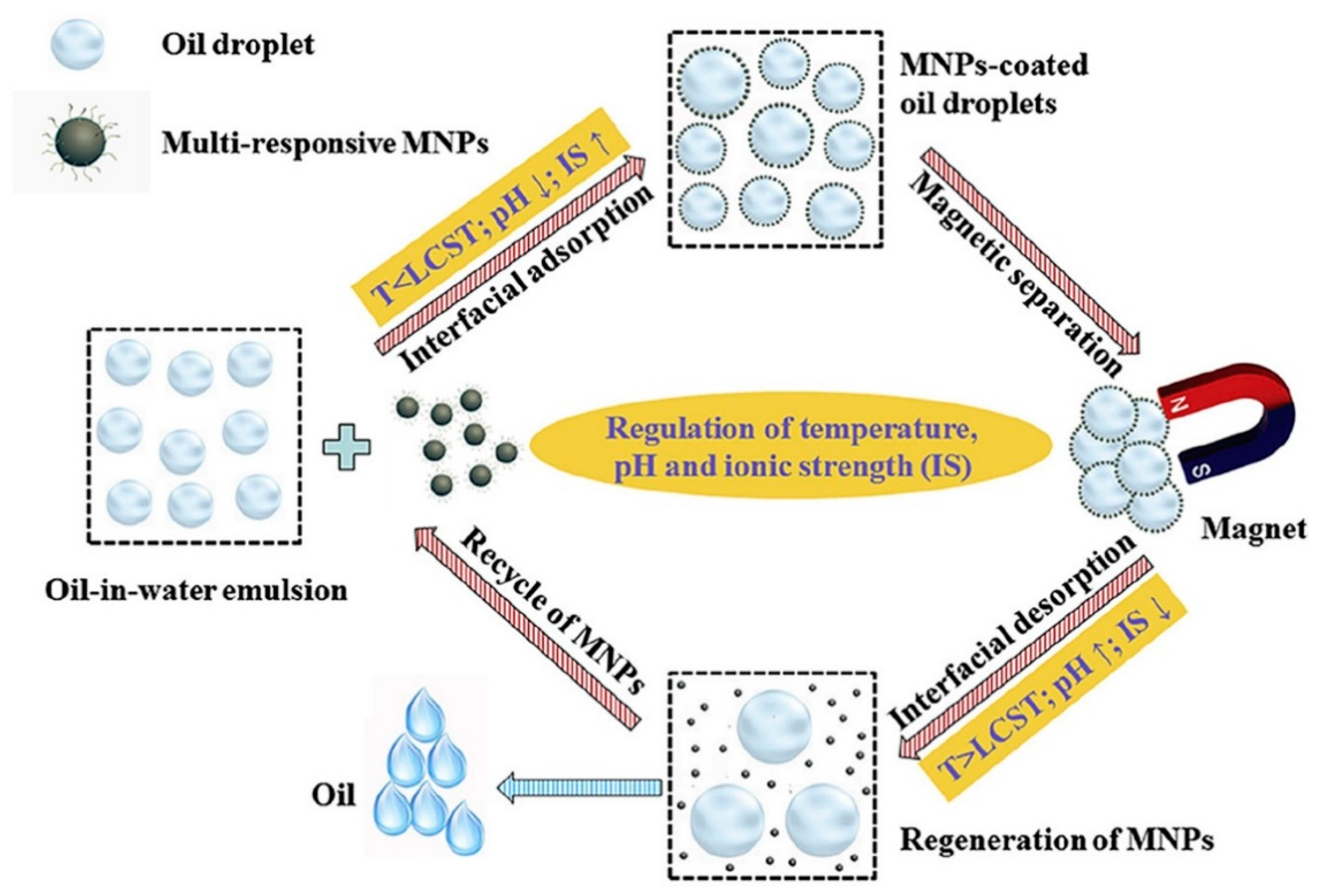
The main problem related to CEB is the regeneration efficiency of material after adsorption. The conventional approach for regeneration involves the physical method of washing using a solvent. The solvent was found to alter the adsorbent’s chemical nature and thus reduce its adsorptive capacity. CEB is illustrated in Figure 5. Magnetic nanoparticles (MNP) were added into the oily wastewater, and an oil removal efficiency of 98% was reported. However, secondary processes are required to remove the oil coated on the surface of the MNP. The recovery of MNP then produces another secondary pollution of oil in the solvent [91]. The efficiency of the CEB method is also dependent on changes in pH, water salinity, exposure time and temperature [92].
Recent research works in oily wastewater cleaning using demulsification techniques are summarized in Table 4. Not much attention is given to physical demulsification. In the chemical and CEB approach, efforts leading to the production of particles with multifunctional properties to enhance adsorption of oil and demulsification, promote degradation of oil and recovery of oil and the regeneration of the particle are prevalent. This method also, in general, could produce high oil removal efficiency by more than 98%. Research on biological methods is still focusing on the discovery and isolation of microorganisms to produce the highest removal efficiency.
Microwave and Ultrasound-Assisted Demulsification Treatment (M-UWT)
Microwave irradiation could be used for the demulsification of oil in wastewater based on two instantaneous mechanisms; one is the rapid increment of oil droplet temperature due to molecular friction and rotation, leading to reduction of emulsion viscosity and thus breaks the outer film of the droplet. Two is molecular rotation, neutralizing Zeta potential due to reorganization of electrical charges around water molecules, which leads to movement of ions around the droplets [103]. The advantages of this method include no usage of chemicals, which eliminates secondary treatment for the removal of those chemicals. This method is environmentally friendly [104].
The overall efficiency of the treatment system could be improved by improving the heating rate of the oil droplet. Many works had been done by incorporating inorganic salts, such as NaCl, CaCl2, KCl and MgCl2, into the treated wastewater to increase water conductivity, which then speeds up the heating rate [105,106]. Kang et al. [107] developed a hybrid system by the combination of microwave demulsification, ozonation, and aerated biological filters to clean wastewater with high microtoxicity. This approach improved the demulsification of oil by about 63.5%. However, in the last decade, not much research was conducted on microwave-assisted demulsification due to the high capital, installation and maintenance cost of this system setup [108,109].
Ultrasound-assisted wastewater treatment is found to be very effective once integrated with electrochemical coagulation. Ultrasound reduces the formation of the dense layers at electrode surfaces and the spread part depth of the electrical double layer at metal surfaces. It also activates ions in the reaction zone surrounding electrodes and activates the electrode’s surface by producing defects in the crystal lattice of the electrodes [110].
3.4. Mechanical Method
In the mechanical method, mechanical coalescers (MC) are used. In MC, small oil droplets collide and adhere to other substances in the coalescers. Larger droplets form and these droplets can be separated by buoyancy due to density difference [111]. The mechanical method effectively separates emulsified oil using MC, especially when the droplet size is less than 10 μm.
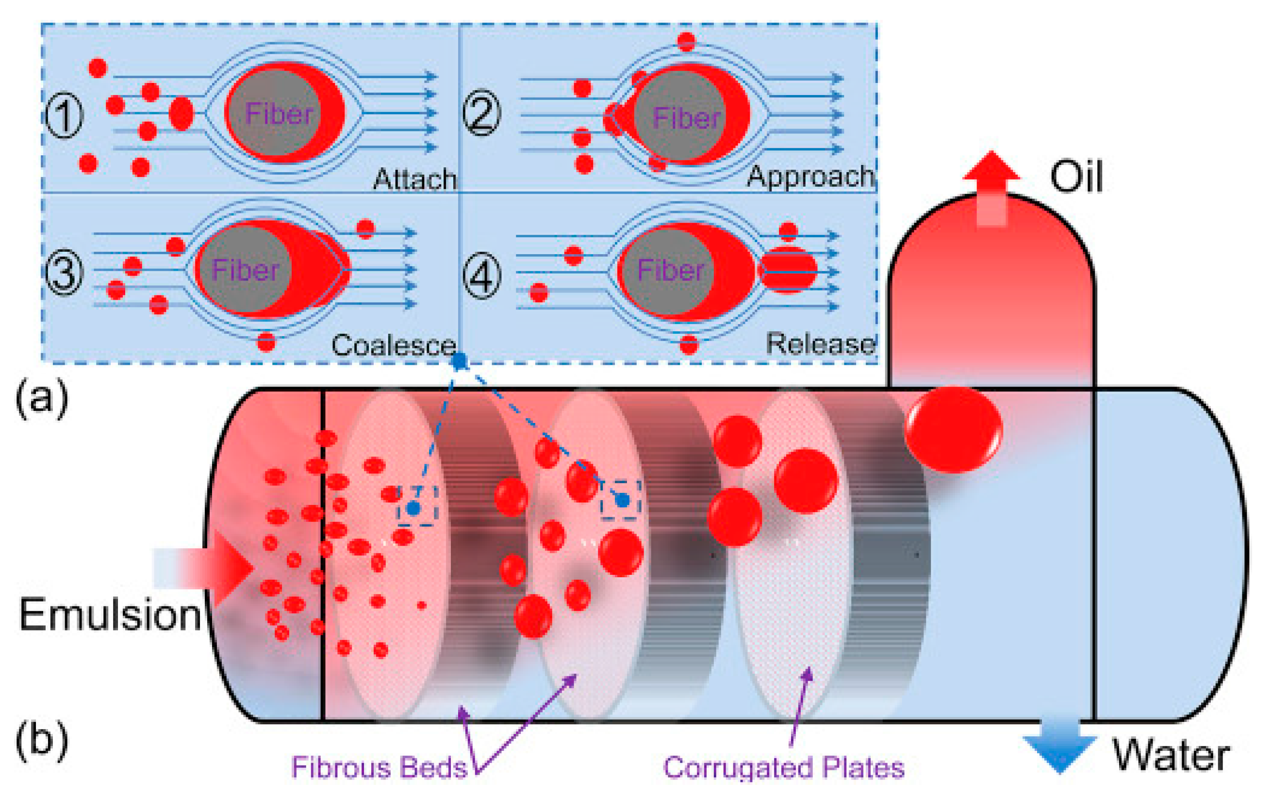
MC is often used in offshore platforms for oily wastewater treatment due to the limitation of space. The coalescers have compact structures, exhibit a long service period, produce efficient separation of liquid–liquid phase, and need a minimum amount of additional chemicals [112]. The common coalescers are plate coalescers, packing coalescers, coalescing filter separators and fibrous coalescers. A novel fibrous coalescer reported in work done by Lu et al. is shown in Figure 6. This coalescer can reduce the offshore produced water oil content from 1200 to 25 mg/L under residence time of 180 s and pressure drop of 30 psi. The coalescence process in this equipment was visualized through four steps; attach, approach, coalesce and release [113].
The selection of suitable coalescers is based on operating conditions and emulsified oil droplet size. Plate and packing coalescers are used to separate emulsified oil with a droplet size of more than 20 microns, while filter separators and fibrous coalescers are used when the droplet size is less than 10 microns [114]. In harsh conditions, such as offshore platforms, fibrous coalescers are preferred because they can withstand vigorous conditions, such as the sudden release of pressure and gas, flow fluctuation and wastewater with high sludge content [115].
The common fibrous coalescers operate through three steps; first, the fibers capture the emulsified droplet when they flow through the fibers; second, the small emulsified droplets continuously collide with each other to form larger droplets, and lastly, the large droplets are released from the fibers when the adhesive force between the droplet and fibers are destabilized using hydrodynamic forces [116]. The principle of oil removal in fibrous coalescer is based on Stokes law [117]. The fibrous coalescer construction material must exhibit great oil absorption capacity, but the absorbed oil particles should not riotously spread on the materials’ surface. Styrene-butadiene rubber (SBR), carbon steel, fiberglass, polypropylene (PP) and ceramic are among the common conventional materials used for the production of fibrous coalescers [118]. Treatment of oily wastewater from Jianghan Oil Field in China, using lipophilic modified ceramic fibrous coalescer, mounted in internal circulating coalescence equipment integrated with flocculation-sedimentation tank and multistage filtration beds showed 78.9% oil separation efficiency after two months of operation [119].
In filter separator coalescers, factors such as high surface wetting and lower drag force are important in ensuring coalescence filtration effectiveness. Various attempts were made to improve surface wetting by producing superoleophilic and superhydrophobic membranes [120], surface-functionalized superoleophilic glass fiber filters [121], hierarchically roughened surface structure on stainless steel fiber [122], and production of heat-treated nanofibers-based filters with high surface area for wetting [123]. In another work by Hu et al. [124], surface wetting of durable composite fibrous filter mat produced through a wet-laying process of glass wool, glass fiber and cellulose fiber was enhanced by forming polymeric nanoparticles on its surface. Oil separation efficiency up to 99.60% could be achieved by this coalescer [125]. The advantages of using filter separators include low cost, ease of operation and selective separation of water and oil [126].
Table 5 presents the recent research works being conducted in the area of MC for oily wastewater cleaning. Most of this research was focused on understanding the mechanism of the system for optimization and practical application.
4. Critical Discussion on the Traditional Methods for Oily Wastewater Cleaning
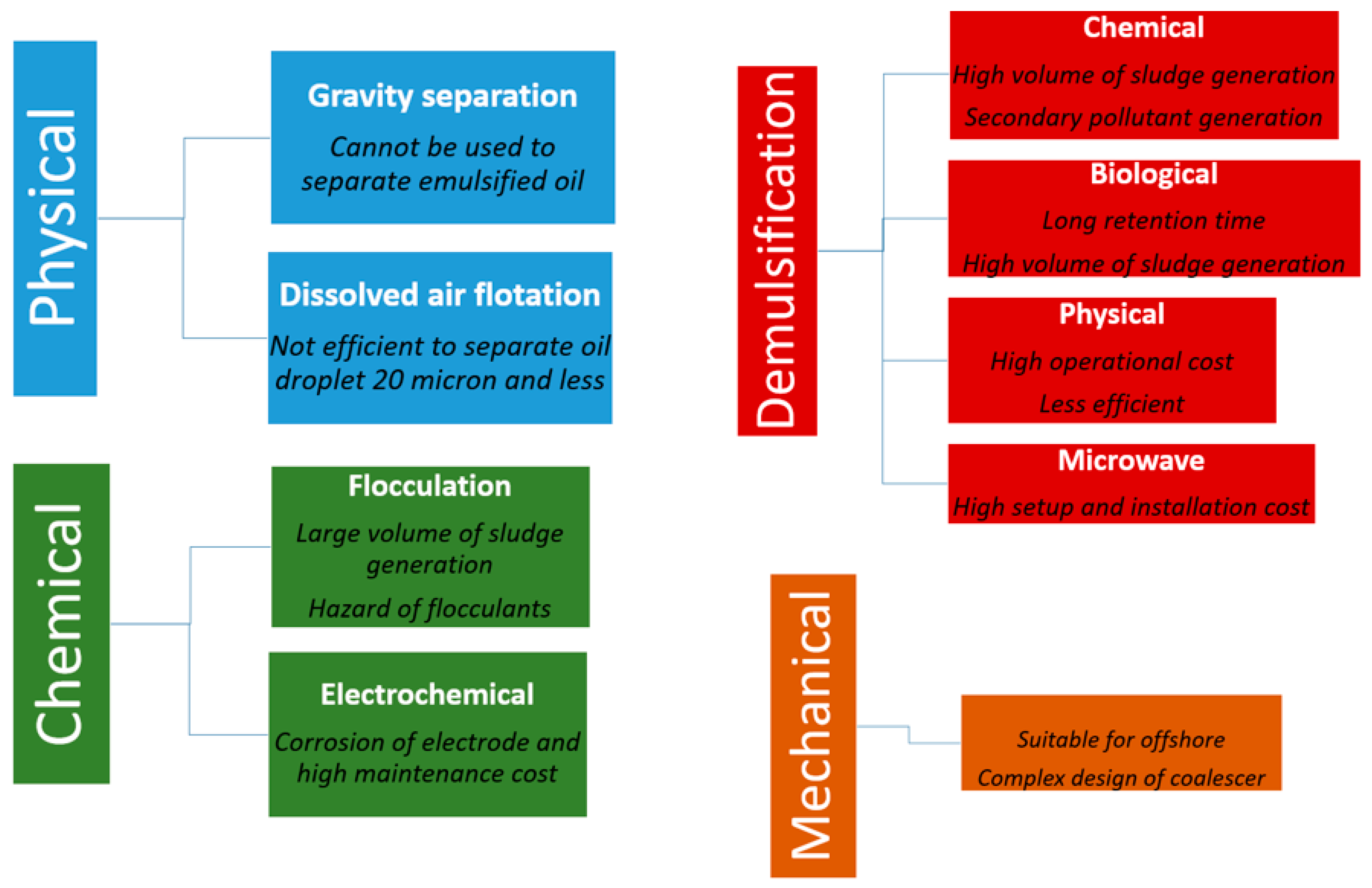
Conventional methods of oily wastewater cleaning are demonstrating ineffective performances. For instance, the DAF cleaning technique can barely separate oil droplets with the size of around 20 microns and less from wastewater. For even smaller droplet sizes, additional units must pretreat the wastewater before flotation [130]. This unavoidably entails a larger footprint and higher capital investments. Meanwhile, the formation of activated sludge is a problem from flocculation and demulsification of oily wastewater cleaning processes because it is harmful when discharged into the open watercourse [131]. Corrosion of electrode material is the limitation of using the ET method [132]. The limitations of each method reviewed in Section 3 are shown in Figure 7.
In short, new or integrated technologies need to be developed due to the following reasons:
- -
- To increase treatment efficiency, reduce operational and maintenance costs of the system due to problems, such as fouling, corrosion, sedimentation and high energy consumption;
- -
- The complex nature of oily wastewater is generated by industry where the discharge contains oil, toxic chemicals, recalcitrant organics, inorganic salts, EPS and biological contaminants [133];
- -
- Development of a more environmentally friendly approach by elimination of secondary pollution, nonbiodegradable substances and sludge formation.
- -
- Integrated systems have shown long-term operational stability compared to stand-alone systems [134];
- -
- Create an opportunity to directly use the recovered oil, water or sludge for applications, such as energy, cleaning water and fertilizer, respectively, without any harm to living things and the environment.
5. Current Modern Techniques for Oily Wastewater Cleaning
Face to the limitation of the conventional methods, several modern techniques are developed based on scientific and technological evolutions. We cite, as an example, biological treatment, supercritical water oxidation, microelectrolysis, and membrane separation technologies.
5.1. Biological Treatment (BT)
Common BT can be classified into aerobic and anaerobic treatment systems. Anaerobic systems require less energy due to the elimination of the aeration process, could convert organic pollutant to methane gas, requires fewer nutrients and produce less sludge [135]. The process can also produce valuable byproducts, such as biodegradable plastics [136]. The aerobic BT is used to treat high temperature and high pollutant concentrated wastewater due to its accelerated biodegradation kinetics [137]. However, in such BT systems, the microbial cells are affected by toxic chemicals and the high salinity of wastewater, which then reduces the system’s overall efficiency.
To overcome this problem, aerobic granulation technology and its application in aerobic granular activated sludge reactor (AGR) has been explored [138,139]. AGR is more stable in oily wastewater treatment due to microbial diversity, compact granule structure, good sedimentation, excellent biomass retention and stability towards toxic pollutants [140]. These aerobic granules’ qualities lead to smaller reactor volume requirements, lower capital cost and instantaneous nutrient removal capacity. Aerobic granulation technology is used to treat wastewater from POME, dairy industry, slop waster and winery [141,142,143].
In recent times aerobic and anaerobic systems are combined to treat oily wastewater without the need for any pretreatment [144]. This approach causes an improvement of treatment efficiency and a reduction in the capital cost and space needed for treatment system setup.BT using membrane bioreactor (MBR) and sequencing batch bioreactor (SBR) is gaining momentum in the area of oily wastewater with a large concentration of organic compound and hydrocarbons [145,146].
Generally, MBR produces high-quality effluent with a small footprint and a low sludge volume [147]. SBR exhibits a robust system and simple operation with wide flexibility [148]. However, the commercial application of MBR and SBR are restraint by lack of confidence in their stability and reliability during operation due to few factors, which affects the continuous efficiency of the system and performance of microorganism used. Issues, such as membrane fouling, modification of biomass biokinetic and characteristic of activated sludge, due to the presence of compounds, such as recalcitrant or xenobiotic in the wastewater, are non-negligible [149]. In produced water, high salinity could cause plasmolysis of the microorganism in the activated sludge and thus affect the metabolism of the microorganism [150].
Thus, BT’s current research trend involves techniques to improve the stability and efficiency to produce a more robust and reliable process. Campo and Bella et al. had cultivated aerobic granules directly in slop wastewater, which mainly contain high molecular weight recalcitrant hydrocarbons to promote gradual adaption of the granules to salinity and hydrocarbon content. These aerobic granules resulted in higher removal of total petroleum hydrocarbon (TPH) than matured aerobic granules cultivated in different media [151]. Usage of bio-carriers in moving biofilm bed reactor-MBR (MBBR-MBR) was reported to promote the growth and stability of nitrifying and denitrifying microbes in a toxic environment and high salinity wastewater, thus makes MBBR-MBR more preferable compared to MBR [152,153].
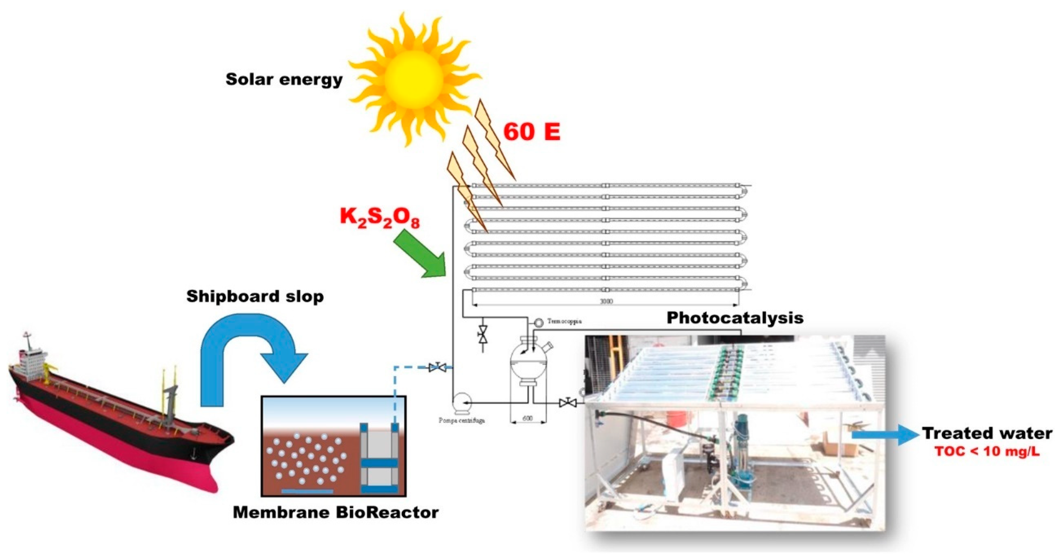
A multidisciplinary approach or integration of technology has resulted in a more robust system. Integrated biofilm treatment and membrane filtration was used to treat POME by Sajjad et al. [154]. Chemical oxygen demand (COD), mixed liquor suspended solids (MLSS), turbidity, total solids content (TSS) and NH3-N removal of 98.6, 97.5, 99.98, 100 and 99.87% were achieved, respectively. Parrino et al. proved that a sequential treatment system involving MBR and photocatalytic reactor (PCR), as shown in Figure 8, could lead to 95% removal of total organic content (TOC) from slop wastewater in which biological treatment, membrane filtration and photocatalytic reaction each contribute 40, 30 and 25% percent removal, respectively [155].
In the integrated system, the shortcomings of each component, such as membrane coking in membrane filtration, low stability of microbial cell in biorecalcitrant compounds, and need for high cumulative impinging energy requirement for the photocatalytic reaction was overcome by another component. In another work by Oliveira et al. [156] MBR system was coupled with an advanced oxidation process (AOP) by adding TiO2 into the system. TiO2 could degrade recalcitrant organic matter in the effluent and thus reduce fouling. The performance of different BT treatment systems reported between 2018 to present is presented in Table 6.
5.2. Supercritical Water Technology (SCW)
Supercritical water oxidation (SCWO) and supercritical water gasification (SCWG) are used to treat heavy oil concentration oily wastewater, such as oily sludge, and it is an alternative technology to incineration [164]. In the SCWO technique, water is utilized above its thermodynamic critical point (374 °C, 22.1 MPa) as reaction media to convert H–C–N compound to H2O, molecular nitrogen and CO2 through an accelerated oxidation process in a very short time [165]. Chlorine, phosphorus and sulfur byproducts are transformed to their equivalent mineral acids or salts upon neutralization with base [166]. The liquid and gas product can be discharged to the environment without the need for any posttreatment [167].
SWCO is a green technique because it is clean, environment-friendly and does not produce any pollutants [168]. SCWO is widely used in the USA and European countries [169]. However, in other parts of the world, SCWO is not popular because of process costs. This process cost could be compensated by recovering the heat energy from SWCO effluent. Espadafor et al. [170] showed that for an SCWO industrial plant with a capacity of 1000 kg/h, a maximum of 118 kW heat could be recovered (71% of energy content).
SCWG exploits the ability of supercritical water to dissolve organic biomass components in wastewater and hydrolysis to break down polymeric biomass structure. The major advantage of SCWG is the ability of the system to generate energy through the gasification of oily wastewater. The yield from SCWG could be divided into gas phase yield, which is often H2, CO2 and CH4 gaseous and liquid phase yield, which is reported in terms of pollutant removals, such as COD, TOC and TSS. Zhiyong and Xiuyi [171] demonstrated TOC removal, hydrogen gasification ratio and carbon gasification ratio of 98%, 128% and 97.88% at temperature 650 °C from oily wastewater using SCWG. In another study by Kipcak et al. [172], SCWG was used to treat complex olive mill wastewater, which contains organic and inorganic fractions. At a reaction temperature of 550 °C, a gas composition with energy content up to 10 kJ per mL olive mill wastewater was formed in just 30 s with more than 90% TOC removal.
The yield and energy generation from SCWG are influenced by parameters, such as temperature, feed concentration and catalyst used. In the past four years, many studies had been conducted to understand the effect of these factors on the gas and liquid phase yield. Extensive work had been conducted to layout the reactions that might occur in SWCO and SCWG systems due to changes in these operating conditions. The research papers in Table 7 have reported that the main reactions occurring during the SCWG process are exothermic methanation reactions, endothermic reforming reaction, water–gas shift reaction laterally with Boudouard coking and coke gasification [173].
5.3. Microelectrolysis
Microelectrolysis is used to treat high concentration oily wastewater, which also contains a large fraction of organic polymers, salt and chemical cleaning agents, such as pre-plating wastewater [179], acid mine drainage [180], and stormwater [181]. Microelectrolysis is a combination of oxidation–reduction, electrochemistry, physical adsorption, flocculation and other function in one process [182]. Treatment processes, such as discoloration, improved flocculation, refractory organic oxidation and enhancement in biodegradability, could be achieved using this one method [183].
Ferric-carbon microelectrolysis uses cast iron scrap and carbon particles in acidic wastewater to generate electrode potential differences among high potential carbon and low potential iron for the production of many tiny proto batteries in the wastewater. Reaction in the cathode (carbon) and anode (iron) produces eco-hydrogen [H] and Fe2+ active species, which can cause chain scission, alter the organic functional group and biodegrade the organic component in oily wastewater [184,185].
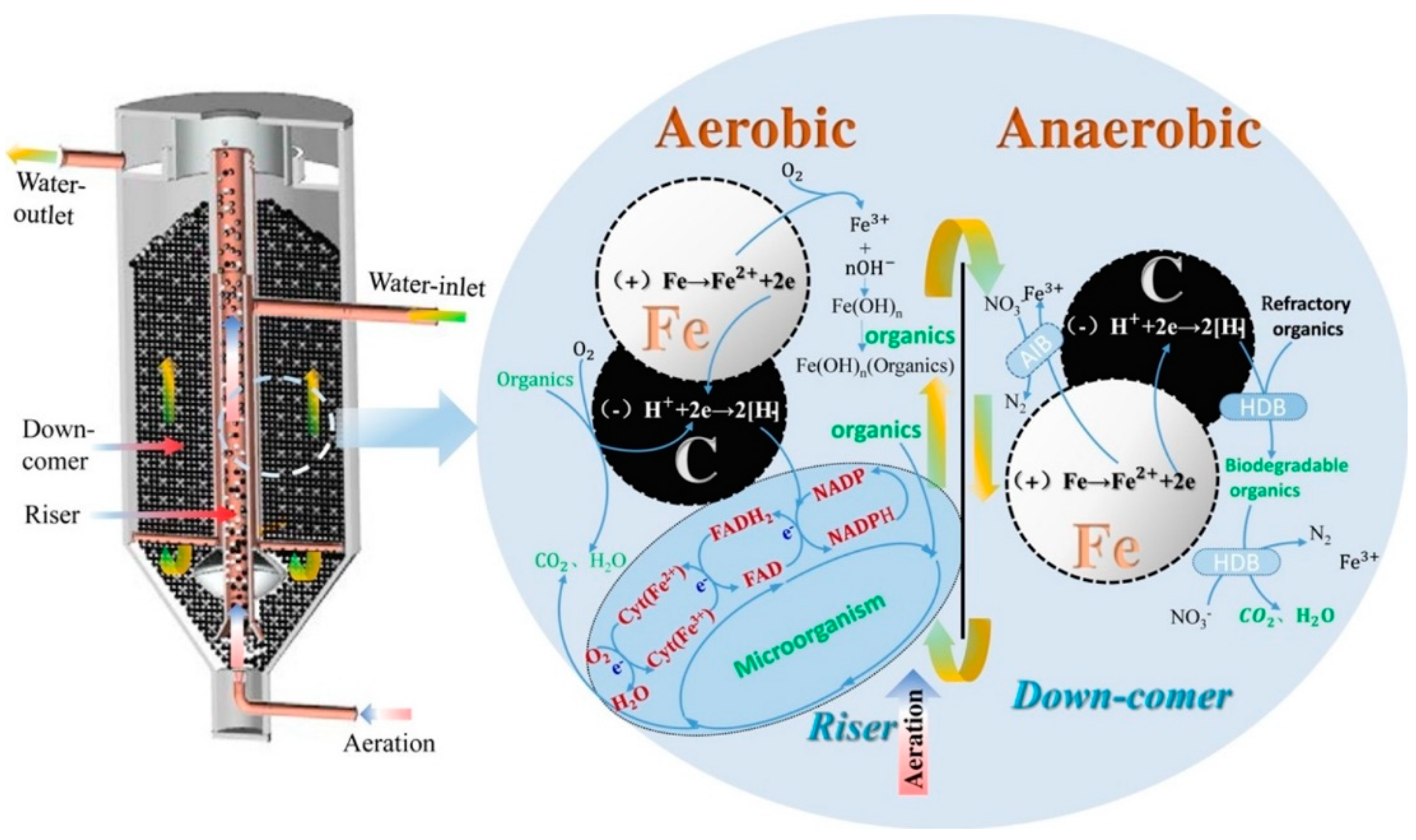
Microelectrolysis is often coupled with another treatment process, such as BT, coagulation and oxidation, to obtain optimum oily wastewater treatment outcome. Zhang [186] combined microelectrolysis, Fenton oxidation and coagulation to treat oilfield fracturing wastewater. Total COD removal efficiency of 85.23% could be achieved, in which the contribution of each process was determined as 68.45% microelectrolysis, 24.07% Fenton oxidation and 7.48% coagulation. Microelectrolysis lead to chain scission, oxidation and redox electroflocculation of organic compound in wastewater. Figure 9 shows the combination of microelectrolysis with a biological system for the treatment of coking wastewater. In this integrated system, two-way electron transfer through the microbial cell was enhanced by Fe2+/Fe3+ and [H] atoms from the microelectrolysis process, thus increasing the metabolism of the microorganisms in the biological system [186].
One of the major disadvantages of this technique for practical application is associated with galvanic corrosion of iron, which leads to reduction of iron reactivity and easy plugging of the system due to accumulation of corrosion product [187]. He et al. [188] combined microelectrolysis with microwave coagulation technology to treat heavy oil wastewater, and this combination was found to reduce corrosion rate by 96.5%. Instantaneously the oil and suspended solids (SS) removal rates of 95.5 and 98.3% were recorded. The performance of the microelectrolysis system under different conditions, such as solid ratio, residence time and pH, had been studied extensively. Reports on work done from 2018 to the present are being summarized in Table 8.
![Water 13 00980 g009]()

Table 8.
Research on the effect of operating conditions on the performance of microelectrolysis oily wastewater treatments from 2018 to recent times.
Table 8.
Research on the effect of operating conditions on the performance of microelectrolysis oily wastewater treatments from 2018 to recent times.
| Type of Wastewater | Treatment System | Operating Condition | Yield Monitored | References |
|---|---|---|---|---|
| Synthetic wastewater containing diesel | Microelectrolysis using Fe–C fillers | Novel microelectrolytic filler prepared using iron powder, carbon powder, bentonite, ammonium bicarbonate, and ionized water. pH = 3 Reaction time = 60 min Fe–C mass ratio: 1:1, 2:1, 3:1, 4:1, 5:1, 6:1 Bentonite loading: 10, 20, 30 wt % | Highest oil removal of 81.4% was achieved at Fe–C ratio of 3:1, bentonite content 20 wt % and pore-former content of 3 wt %. - - - - | [189] |
| Ship sewage | Microelectrolysis using Fe–C fillers | Solid–liquid ratio of filler: 1:20, 1:10, 1:5, 1:4, 1:2. Reaction time: 10, 20, 30, 40, 50, and 60 min. pH: 1, 2, 3, 4, 5, 6, 7 | Highest removal of oil (80.1%) and landfill leachate sludge (LLS) (77%) was achieved at a solid–liquid ratio of 1:4, pH 3 and reaction time of 60 min. | [190] |
| Coking wastewater | Microelectrolysis biological fluidized bed (MBFB) | - | COD and total nitrogen removal rates of 92 and 95%. | [191] |
| Turpentine processing industry wastewater | Microelectrolysis by Fe–C filler combined with Fenton oxidation | Both batch and continuous system. An adsorption method using activated carbon was carried out for comparison. | By combining the two systems, more than 15,000 mg/L of COD can be degraded, which is higher than using the activated carbon absorption treatment method (9000–15,000 mg/L) | [192] |
Figure 9.
Combination of microelectrolysis and membrane bioreactor (MBR). Reprinted with permission from ref. [190]. Copyright 2020 Elsevier Ltd.
Figure 9.
Combination of microelectrolysis and membrane bioreactor (MBR). Reprinted with permission from ref. [190]. Copyright 2020 Elsevier Ltd.

5.4. Membrane Separation Technology (MST)
In the last decade, MST for oily wastewater treatment had been studied extensively due to its capability to remove most of the chemicals and inorganic and organic compounds from wastewater [193]. MST requires a smaller area of land compared to other conventional methods and thus has a small carbon footprint [194]. Effective, selective and consistent separation of pollutants could be achieved using MST. MST also exhibits good productivity, stability, low defect rate and economical to use [195]. It is worth mentioning that the quality of the treated water is mostly consistent for all influent variations. Additionally, it can be used in the recycling of selected waste streams for different applications [196,197,198]. Currently, polymer and ceramic membranes are being vastly studied for oily wastewater filtration.
MST could be first classified into three categories based on the driving force used for separation; pressure-driven, osmotic driven and thermally driven. Among these three-driving forces, pressure-driven is the most popular category used for oily wastewater treatment [195]. The pressure-driven membrane could be further classified into reverse osmosis (RO), nanofiltration (NF), ultrafiltration (UF), and microfiltration (MF) [199]. Microfiltration and ultrafiltration processes to treat oily wastewater have previously been reported, with UF being the preferred technique because it is a low-pressure operation and thus needs low capital and operating cost [200].
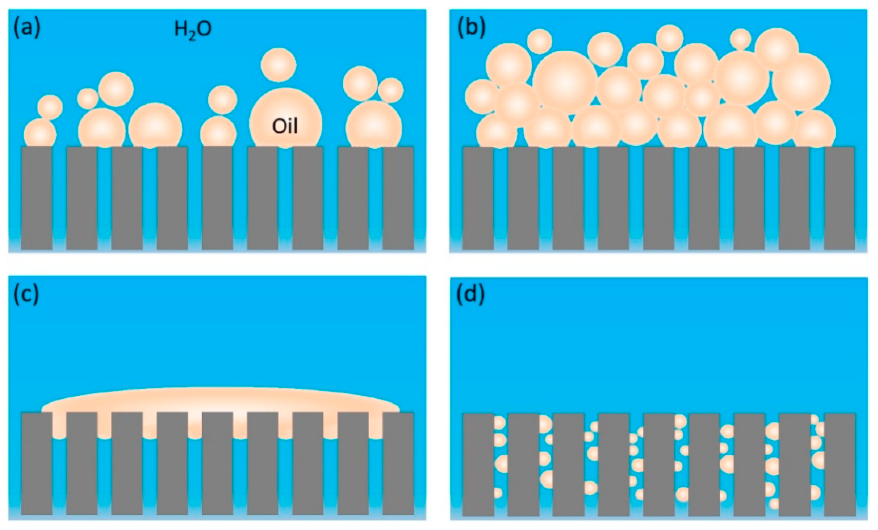
However, for practical application, the major challenge faced by these membranes are poor long-time stability, fouling and short membrane lifetime [201]. Oil droplets could gather on the membrane surface or inside the pore channels, which then block the water permeation through the membrane at constant trans-membrane pressure (TMP). This problem is more prominent in the hydrophobic polymeric membrane. To overcome this problem, cleaning is carried out through backward flush, chemical cleaning and air flush to maintain membrane performance, but the cleaning process was found to reduce membrane lifetime [202]. Cleaning also increases the operational cost of MST. Fouling problem in membrane had been illustrated in detail by Huang et al. [203], Figure 10.
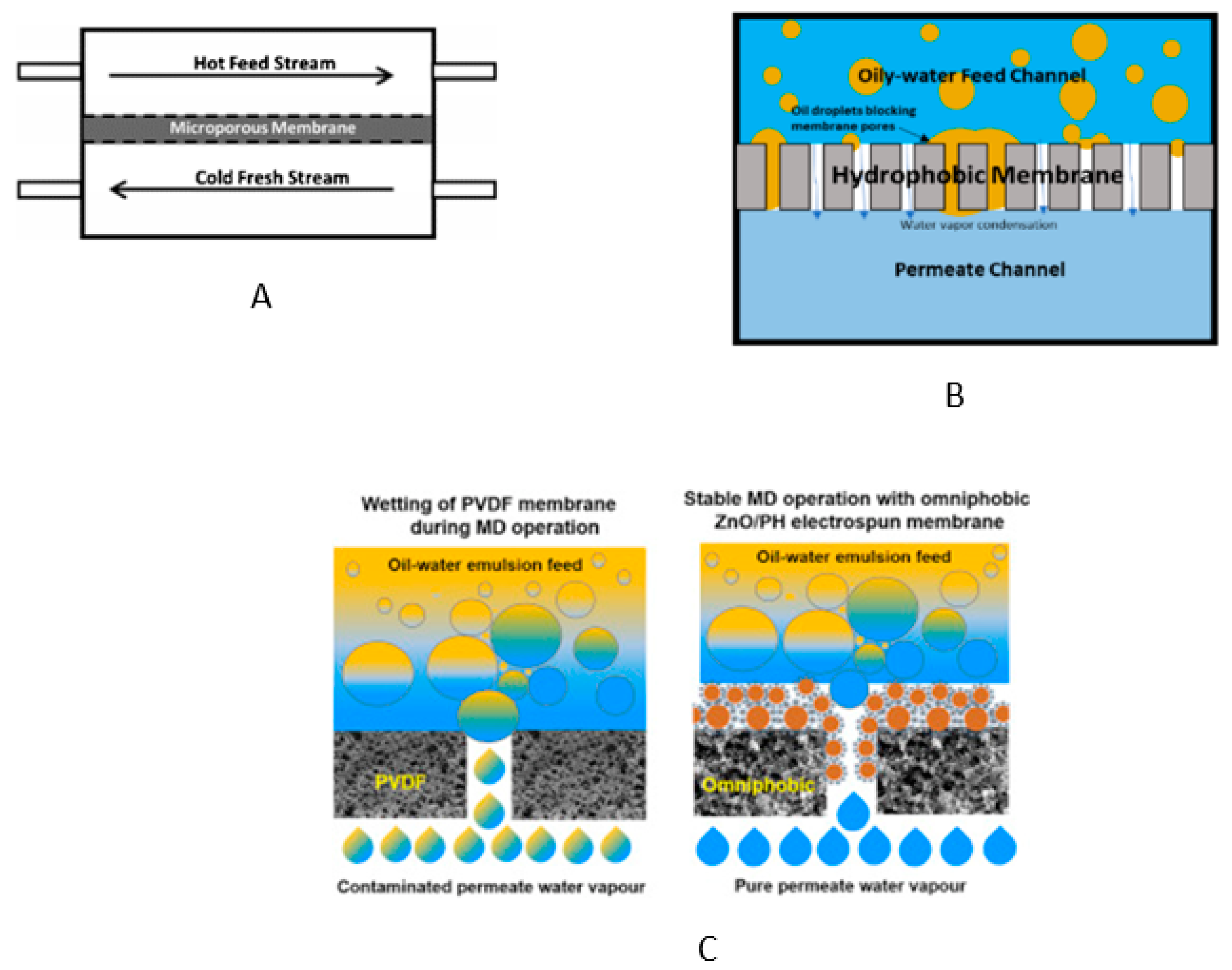
A thermally driven MST known as membrane distillation (MD) had been studied extensively in saline water purification, but more recently, research interest to use this approach for oily wastewater separation is emerging. Direct contact membrane distillation was studied for the treatment of refinery process wastewater, shale oil wastewater and vegetable oil wastewater [204]. The main challenge in the application of this method in oily wastewater separation is membrane wetting, where the oil starts to penetrate into the membrane pores [205]. Omniphobic membranes, which can repel high and low surface tension liquid and remain unwetted in oily wastewater separation systems, are being extensively researched to overcome this challenge [206,207]. Schematic diagram of counterflow direct contact membrane distillation system, blocking of hydrophobic membrane pores, and the comparison on omniphobic membrane with a conventional hydrophobic membrane is illustrated in Figure 11 [208,209].
5.4.1. Polymeric Membrane
The most commonly used polymeric membranes are poly(ether sulfone) (PES), PTFE, PP, polyvinylidene fluoride (PVDF) and polyethylene (PE) [210]. They are used for MF and UF [211]. The hydrophilic polymeric membrane gives more successful treatments than the hydrophobic type [212]. A good membrane must exhibit superhydrophilic and underwater superoleophobic properties. These properties are often achieved by decorating the membrane with particles, such as halloysite nanotube [213], cellulose [214], SiO2 [215], TiO2 [216], and Al2O3 [217] to produce a rough surface on the membrane to improve wetting. These particles are used because they have functional groups, such as carboxyl, hydroxyl, amino and sulfonic, on their surfaces [218]. In situ modifications by blending these particles in the polymer dope solutions are also used to improve the wettability of the polymeric membranes.
A major issue of polymeric membrane application is fouling, which results in a gradual decrease in permeation flux and separation efficiency during its operation. Fouled polymer membranes are regenerated through chemical cleaning with strong oxidants [219] and photocatalysis [220]. These methods lead to membrane corrosion, reduce membrane wettability and service life and cause photodegradation of membrane material [221,222]. Calcination of polymer membrane to degrade organic matter could be one potential approach to solve fouling problems. However, the polymer membrane needs to be constructed from thermally stable engineering plastics, such as polysulfonamide (PSA), for the calcination to be carried out.
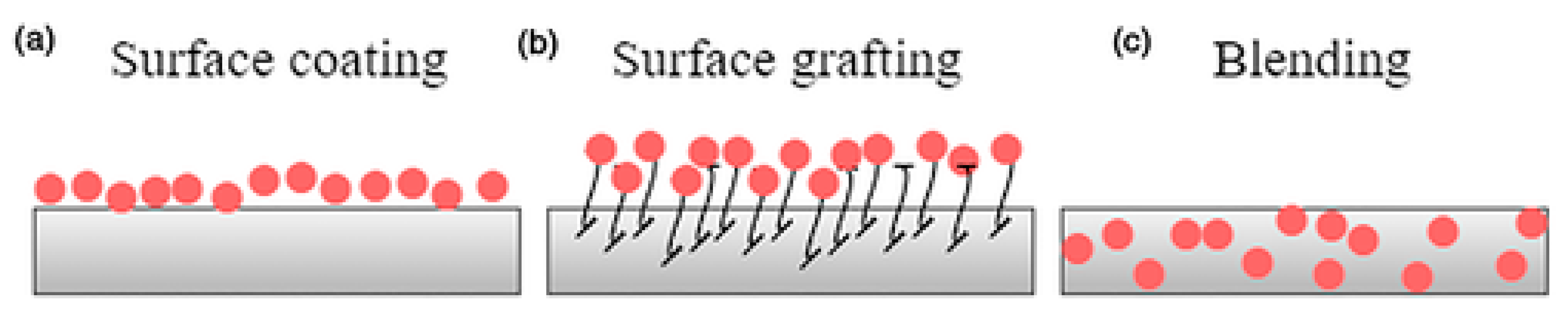
In recent studies, vast focus has been given to increase the hydrophilic properties of polymer membrane and reduction of fouling through membrane modification techniques. Membrane modification techniques can be classified into the surface coating, surface grafting and blending, as shown in Figure 12. Nanomaterials, such as nanosized ZrO2, silica nanoparticles, Cu2O nanoparticles and graphene oxide, are often used to modify the membrane through all these three techniques due to their large surface area and a high number of functional groups [223]. Nanomaterials can change the pore structure, membrane surface morphology, produce uniform coatings, increase hydrophilicity and reduce membrane fouling [224]. The modifications of polymeric membranes and their effects on MST performance are discussed in Table 9.
5.4.2. Ceramic Membranes
Among the advantages of ceramic membrane compared to polymeric membrane includes narrow and well-defined pore size distribution, greater porosity, enhanced separation and flux, superior chemical, mechanical and thermal stability, longer membrane lifetime, more hydrophilic and exhibit high fluxes at low pressure and has lower fouling [230,231,232]. Recovery of the ceramic membrane could be easily done through calcination. Ceramic membranes are also implausible to bacterial degradation due to bio-fouling compared to polymeric membranes [233]. The drawback of this membrane includes difficult handling due to the brittle nature of the membrane, high cost of fabrication and fouling [234].
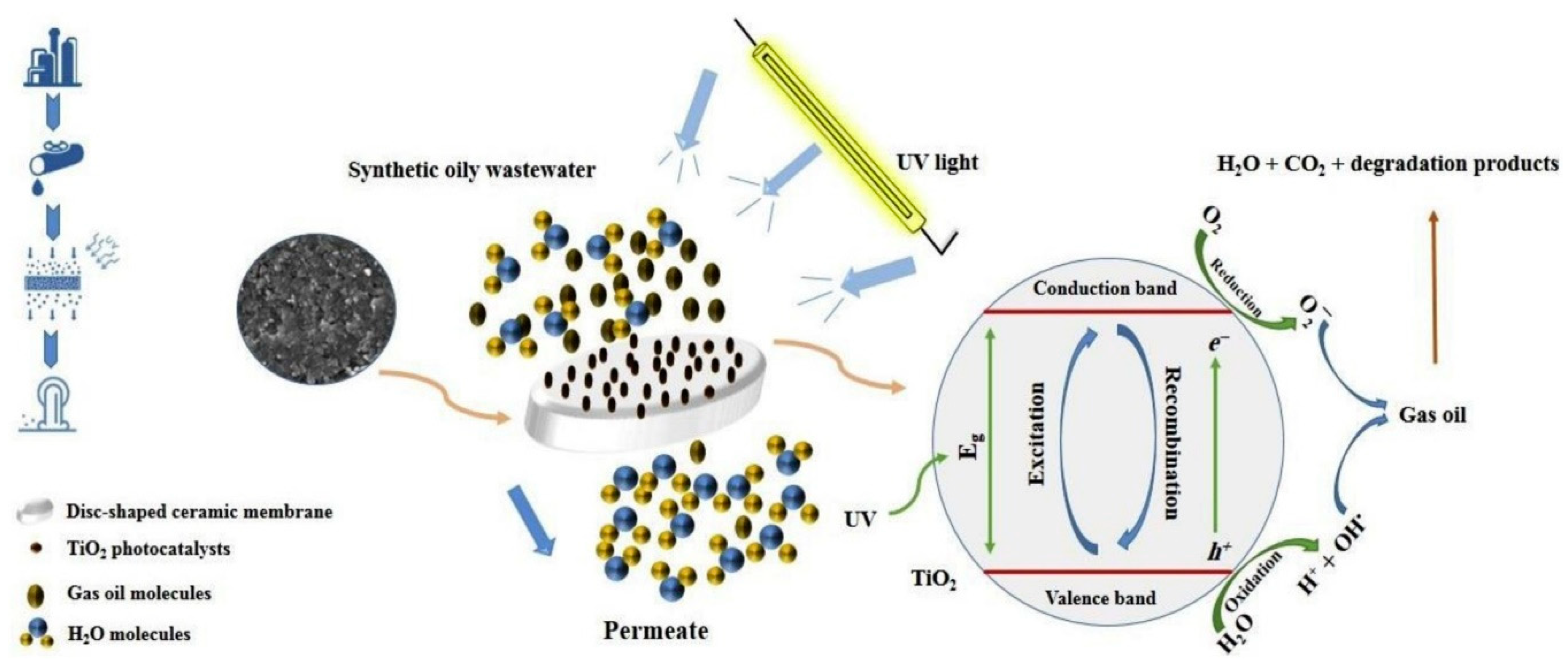
Table 10 presents research that has been carried out in the past three years to solve the ceramic membrane fouling problem and improve water flux. Most of these attempts involve the integration of MF with other systems, such as EC, filtration and advance oxidation process (AOP). Among these methods of integration, AOP produces better results in terms of water flux and reduction of fouling in ceramic MF systems. The incorporation of EC generally reduces the efficiency of the whole system. An example of a hybrid system of AOP using a photocatalytic reactor and MF ceramic membrane is shown in Figure 13.
5.4.3. Critical Analysis
As reported, it is clear that the MST is a multiphysical method involving fundamental biology, membrane materials, processes and mechanisms, and hybridization philosophy. Membrane filtration has a large potential for cleaning oil from oily wastewater due to its advantages in terms of energy efficiency, easy process, and low maintenance cost. Even though membrane separation technology is superior to the conventional methods of treating oily wastewater, there are also some drawbacks of employing membranes. However, the main barriers to the practical use of membrane filtration in oily wastewater cleaning are identified as membrane fouling, low chemical resistance, low mechanical properties, and the tradeoff effect between permeation flux and rejection rate. In fact, membrane fouling is invariable when subjected to heavy, oily wastewater cleaning [240]. The fact that oil components can easily block membrane pores imposes an arduous challenge to membrane applications in oily wastewater cleaning. Moreover, a high rejection rate and high permeation flux can never be achieved simultaneously when using the existing membranes. One of the parameters must be compromised. Thus, the optimal solutions to both permeation flux and rejection rate must be determined [111].
However, the oil components in oily wastewater can easily cause fouling of the membrane, leading to lower efficiency of the membrane. In other words, membrane fouling remains as one of the main technical challenges in the wastewater separation industries [72]. Many types of membranes were tested and evaluated, and they were the subject of research and development. Particularly, polymeric membranes have low mechanical strength, thermal stability, and chemical resistance [201]. This limits the applications of membranes in severe conditions. The criteria that must be fulfilled by a membrane to serve as an excellent oily wastewater cleaning agent are superior chemical resistance and mechanical strength, high rejection rate, as well as high water flux and less fouling effect. Moreover, it has acquired an inherent hydrophobic surface, which is subjected to fouling and hindering the membrane from performing well [38]. Moreover, another common limitation of the polymeric membrane is the tradeoff effect between the permeation flux and rejection rate [111].
6. Future Opportunities of Oily Wastewater Treatment
Despite the application of all the technologies discussed in Section 5, oily wastewater treatment technology is still energy-intensive, unstable, needs high operational and installation costs and does not produce the expected yield. The application of advanced techniques, nanotechnology and integration of the system is required for efficient and cost-effective oily wastewater treatment. In this section, the future direction of each oily wastewater treatment system is highlighted and discussed.
- (a)
- Future directions of membrane separation technologies (MST)The main focus in research of MST is to overcome the fouling and tradeoff effect between the water flux and rejection rate of oil. These problems could be addressed by the following means:
- (i)
- Improve the wetting behavior of membrane surface with water and reduce the interaction with oil droplet. This could be achieved by increasing the water contact angle to be more than 150° and the oil contact angle to be less than 10°. A system that mimics nature should be deposited on the surface of the membrane either by chemical modification or changes in surface roughness. However, techniques for the formation of such a structure should be fast and cost-effective. The structure also must exhibit stability upon exposure to operating pressure, salinity and chemical composition in wastewater;
- (ii)
- Problems in the application of nanomaterials, such as poor dispersion of nanomaterials inside polymer dope, had to be overcome by introducing new methods to prepare the dope, such as compounding the dope in latex/emulsion base system. Nanofillers with oxygen functional groups, such as GO, could be easily dispersed in the latex/emulsion system;
- (iii)
- Polymer membrane could be produced using high-temperature resistance polymers, which could be calcined for recovery.
- (b)
- Future direction of biological treatment (BT) systemsThe main challenge for the development of the biological treatment system is the preserve the stability of the system upon exposure to high salinity and toxicity of the wastewater stream. The stability could be achieved by the following methods:
- (i)
- More focus should be given to the integration of system where toxic chemicals and salinity are reduced by other treatment approaches before the feed is channeled to BT;
- (ii)
- Stimulation, correlation and experimental study on the synergistic effect of each component in the integrated system mainly focusing on the microorganism activity should be explored vastly;
- (iii)
- Exploring the stability of the microorganism when exposed to chemical and thermal shock in the BT system.
7. Conclusions
This review had provided insight into the latest development in oily wastewater treatment from 2018 to the present. In this period, integrating various techniques to enhance performance, reliability, eliminate secondary waste or pollution and reduce the operational cost of oily wastewater treatment systems could be observed. More research works are focused on the system’s operational parameters in the field compared to previous times. Within this period, advancement in material science related to oily wastewater cleaning systems, such as extensive development in membrane material, photocatalytic nanoparticles and flocculants, was carried out. Modification of these materials to achieve superior cleaning properties had resulted in higher cleaning efficiency, as never been reported before. However, the reliability of a single system or method is still questionable, and thus, the practical way to move forward is by integrating a few systems or methods. More studies should be conducted to understand the chemical, physical and economic aspects of these integrations. Modeling, operational parameter studies, and the integrated system design will accelerate the practical implementation of oily wastewater cleaning integrated systems in real scenarios.
Author Contributions
Conceptualization, K.A. and M.K.; methodology, M.K.; validation, Y.M.; formal analysis, Y.T.J. and M.A.; investigation, K.A. and M.K.; resources, M.K. and M.A.; writing—original draft preparation, M.K. and K.A.; supervision, K.A. and M.K.; project administration, K.A.; funding acquisition, K.A. All authors have read and agreed to the published version of the manuscript.
Funding
This research was funded by Deputyship for Research & Innovation, Ministry of Education in Saudi Arabia, grant number 32 and the APC was funded by the project indicated above.
Institutional Review Board Statement
Not applicable.
Informed Consent Statement
Not applicable.
Data Availability Statement
The study did not report any data.
Acknowledgments
The authors extend their appreciation to the Deputyship for Research & Innovation, Ministry of Education in Saudi Arabia, for funding this research work through project number 32.
Conflicts of Interest
The authors declare no conflict of interest. The funders had no role in the design of the study, in the collection, analyses, or interpretation of data, in the writing of the manuscript, or in the decision to publish the results.
Abbreviations
| AC | Current |
| ACM | Activated carbon nanoparticles |
| ACR | Anaerobic contact reactor |
| AGR | Activated sludge reactor |
| AOP | Advanced oxidation process |
| APTES | 3-Amino triethoxysilane |
| BMDAC | Benzyl(methacrylooyoxyethyl) dimethylammonium chloride |
| BOD | Biological oxygen demand |
| BT | Biological treatment |
| CD | Current density |
| CE | Energy conversion efficiency |
| CEB | Chemical emulsion breaking |
| CFD | Computational fluid dynamics |
| COD | Chemical oxygen demand |
| CN | Carbon nitride nanosheets |
| DAF | Dissolved air flotation |
| DC | Direct current |
| EIO | Indirect electro-oxidation |
| EO | Electrochemical oxidation |
| EPS | Intercellular polymer substances |
| ET | Electrochemical technology |
| EU | European Union |
| F-CB | Functionalized carbon black |
| FE3O4 | Magnetic seed |
| FE3O4@OA | Magnetic nanoparticles coated with oleic acid |
| GAC | Granular activated carbon |
| GS | Gravity separation |
| HNT | Halloysite nanotubes |
| HRT | Hydraulic retention time |
| LCST | Critical solution temperature |
| MBFB | Microelectrolysis biological fluidized bed |
| MBBR-MBR | Moving biofilm bed reactor-MBR |
| MBR | Membrane bioreactor |
| MC | Mechanical coalescence |
| MD | Membrane distillation |
| MgCl2 | Magnesium chloride |
| MF | Microfiltration |
| MLSS | Mixed liquor suspended solids |
| MST | Membrane separation technology |
| M-rGO | Reduced graphene oxide with magnetic nanoparticles |
| M-UWT | Microwave and ultrasound treatment |
| NaCl | Sodium chloride |
| NB | Nanobubbles |
| NF | Nanofiltration |
| OCA | Oil contact angle |
| OMSW | Oily micropolluted surface water |
| Ox-CB@SiO2 | Oxidized carbon black modified with SiO2 |
| PAB | Cationic PAM copolymer |
| PAC | Poly(aluminum chloride) |
| PAM | Polyacrylamide |
| PANFM | PAN fibrous membrane |
| PCR | Photocatalytic reactor |
| PDBC | Poly(dimethyl acryloxyethyl benzyl ammonium chloride) |
| PDMS | Polydimethylsiloxane |
| PE | Polyethylene |
| PES | Poly(ether sulfone) |
| POME | Palm oil mill effluent |
| PP | Polypropylene |
| PSA | Polysulfonamide |
| PTFE | Polytetrafluoroethylene |
| PVDF | Polyvinylidene fluoride |
| PVOH | Polyvinyl alcohol |
| rGO | Reduced graphene oxide |
| RO | Reverse osmosis |
| SBR | Styrene-butadiene rubber |
| SCW | Supercritical water technology |
| SD-ALR | Airlift loop reactor |
| SRT | Sludge retention time |
| TIF | Poly(acrylamide-co-N,N-diethylacrylamide-co-n-butylstyrene) |
| TOC | Total organic content |
| TMP | Trans-membrane pressure |
| TPH | Total petroleum hydrocarbon |
| TP-ADL | Amphiphilic polyacrylamide with cationic micro block structure |
| TSS | Total suspended solids |
| UF | Ultrafiltration |
| UN | United Nations |
| WFD | Water Framework Directive |
References
- Obotey Ezugbe, E.; Rathilal, S. Membrane technologies in wastewater treatment: A review. Membranes 2020, 10, 89. [Google Scholar] [CrossRef]
- Hakak, S.; Khan, W.Z.; Gilkar, G.A.; Haider, N.; Imran, M.; Alkatheiri, M.S. Industrial wastewater management using blockchain technology: Architecture, requirements, and future directions. IEEE Internet Things Mag. 2020, 3, 38–43. [Google Scholar] [CrossRef]
- UNESCO. The United Nations World Water Development Report 2017: Wastewater the Untapped Resource; UNESCO: Paris, France, 2017. [Google Scholar]
- Chen, B.; Yang, S.; Cao, Q.; Qian, Y. Life cycle economic assessment of coal chemical wastewater treatment facing the ‘Zero liquid discharge’industrial water policies in China: Discharge or reuse? Energy Policy 2020, 137, 111107. [Google Scholar] [CrossRef]
- Mesa-Pérez, E.; Berbel, J. Analysis of barriers and opportunities for reclaimed wastewater use for agriculture in Europe. Water 2020, 12, 2308. [Google Scholar] [CrossRef]
- Rodriguez, D.J.; Serrano, H.A.; Delgado, A.; Nolasco, D.; Saltiel, G. From Waste to Resource: Shifting Paradigms for Smarter Wastewater Interventions in Latin America and the Caribbean; World Bank: Washington, DC, USA, 2020. [Google Scholar]
- Cai, Y.; Chen, D.; Li, N.; Xu, Q.; Li, H.; He, J.; Lu, J. A Self-Cleaning Heterostructured Membrane for Efficient Oil-in-Water Emulsion Separation with Stable Flux. Adv. Mater. 2020, 32, 2001265. [Google Scholar] [CrossRef]
- Ahmad, T.; Guria, C.; Mandal, A. A review of oily wastewater treatment using ultrafiltration membrane: A parametric study to enhance the membrane performance. J. Water Process Eng. 2020, 36, 101289. [Google Scholar] [CrossRef]
- Putatunda, S.; Bhattacharya, S.; Sen, D.; Bhattacharjee, C. A review on the application of different treatment processes for emulsified oily wastewater. Int. J. Environ. Sci. Technol. 2019, 16, 2525–2536. [Google Scholar] [CrossRef]
- AlJaberi, F.Y.; Abdulmajeed, B.A.; Hassan, A.A.; Ghadban, M.L. Assessment of an electrocoagulation reactor for the removal of oil content and turbidity from real oily wastewater using response surface method. Recent Innov. Chem. Eng. (Former. Recent Pat. Chem. Eng.) 2020, 13, 55–71. [Google Scholar] [CrossRef]
- Zhao, C.; Zhou, J.; Yan, Y.; Yang, L.; Xing, G.; Li, H.; Wu, P.; Wang, M.; Zheng, H. Application of coagulation/flocculation in oily wastewater treatment: A review. Sci. Total Environ. 2020, 765, 142795. [Google Scholar] [CrossRef]
- Maguire-Boyle, S.J.; Barron, A.R. A new functionalization strategy for oil/water separation membranes. J. Membr. Sci. 2011, 382, 107–115. [Google Scholar] [CrossRef]
- Alardhi, S.M.; AlJaberi, F.Y.; AlSaedi, L.M. Studying the treatability of different types of nanoparticles for oil content removal from oily wastewater produced from refinery process. Egypt. J. Chem. 2020, 63, 4963–4973. [Google Scholar] [CrossRef]
- Akpor, O.B.; Otohinoyi, D.A.; Olaolu, T.D.; Aderiye, B.I. Pollutants in wastewater effluents: Impacts and remediation processes. Int. J. Environ. Res. Earth Sci. 2014, 3, 50–59. [Google Scholar]
- Hui, L.; Yan, W.; Juan, W.; Zhongming, L. A review: Recent advances in oily wastewater treatment. Recent Innov. Chem. Eng. (Former. Recent Pat. Chem. Eng.) 2015, 7, 17–24. [Google Scholar] [CrossRef]
- Han, M.; Zhang, J.; Chu, W.; Chen, J.; Zhou, G. Research Progress and Prospects of Marine Oily Wastewater Treatment: A Review. Water 2019, 11, 2517. [Google Scholar] [CrossRef] [Green Version]
- Dickhout, J.M.; Moreno, J.; Biesheuvel, P.M.; Boels, L.; Lammertink, R.G.; de Vos, W.M. Produced water treatment by membranes: A review from a colloidal perspective. J. Colloid Interface Sci. 2017, 487, 523–534. [Google Scholar] [CrossRef]
- Holdich, R.G.; Cumming, I.W.; Smith, I.D. Crossflow microfiltration of oil in water dispersions using surface filtration with imposed fluid rotation. J. Membr. Sci. 1998, 143, 263–274. [Google Scholar] [CrossRef]
- Chen, A.S.C.; Flynn, J.T.; Cook, R.G.; Casaday, A.L. Removal of oil, grease, and suspended solids from produced water with ceramic crossflow microfiltration. SPE Prod. Eng. 1991, 6, 131–136. [Google Scholar] [CrossRef]
- Tanudjaja, H.J.; Hejase, C.A.; Tarabara, V.V.; Fane, A.G.; Chew, J.W. Membrane-based separation for oily wastewater: A practical perspective. Water Res. 2019, 156, 347–365. [Google Scholar] [CrossRef]
- Liew, W.L.; Kassim, M.A.; Muda, K.; Loh, S.K.; Affam, A.C. Conventional methods and emerging wastewater polishing technologies for palm oil mill effluent treatment: A review. J. Environ. Manag. 2015, 149, 222–235. [Google Scholar] [CrossRef] [Green Version]
- Yu, L.; Han, M.; He, F. A review of treating oily wastewater. Arab. J. Chem. 2017, 10, S1913–S1922. [Google Scholar] [CrossRef] [Green Version]
- Tayim, H.A.; Al-Yazouri, A.H. Industrial Wastewater Treatment Using Local Natural Soil in Abu Dhabi, U.A.E. Am. J. Environ. Sci. 2005, 1, 190–193. [Google Scholar]
- Available online: http://www.cpcbenvis.nic.in/scanned%20reports/PCL%204%20Environmental%20Standards.pdf (accessed on 20 March 2021).
- Le, T.V.; Imai, T.; Higuchi, T.; Yamamoto, K.; Sekine, M.; Doi, R.; Vo, H.T.; Wei, J. Performance of tiny microbubbles enhanced with “normal cyclone bubbles” in separation of fine oil-in-water emulsions. Chem. Eng. Sci. 2013, 94, 1–6. [Google Scholar] [CrossRef]
- Hanafy, M.; Nabih, H.I. Treatment of Oily Wastewater Using Dissolved Air Flotation Technique. Energy Sources Part A 2007, 29, 143–159. [Google Scholar] [CrossRef]
- Nordvik, A.B.; Simmons, J.L.; Bitting, K.R.; Lewis, A.; Strøm-Kristiansen, T. Oil and water separation in marine oil spill clean-up operations. Spill Sci. Technol. Bull. 1996, 3, 107–122. [Google Scholar] [CrossRef]
- Gang, Z.M.F.S.W.; Zhongming, W. A Research on Oily-Water Gravity Separating Mathematical Model and Its Application. J. SSSRI 1998, 2. Available online: https://www.tandfonline.com/doi/pdf/10.1080/009083190948711?casa_token=I6iYLIyCJHsAAAAA:uj5TCNfhFmXkbYuBIFW-gj5PRv6PWoTvlbDppmF3o4BC_r8HoHqcBiFfp5tdpp6R2jv-ERuWM4QaaVK0Zw (accessed on 31 March 2021).
- Kenawy, F.A.; Kandil, M.E.; Fouad, M.A.; Aboarab, T.W. Produced water treatment technology, a study of oil/water separation in gravity type cross flow pack separators for qualitative separation. SPE Prod. Facil. 1997, 12, 112–115. [Google Scholar] [CrossRef]
- David, H.F.; Liptak, B.G. Wastewater Treatment; Lewis Publishers: New York, NY, USA, 2000. [Google Scholar]
- Mysore, D.; Viraraghavan, T.; Jin, Y.C. Oil/water separation technology-A review. J. Residuals Sci. Tech. 2006, 3, 5–14. [Google Scholar]
- Xing, Y.; Gui, X.; Pan, L.; Pinchasik, B.E.; Cao, Y.; Liu, J.; Kappl, M.; Butt, H.J. Recent experimental advances for understanding bubble-particle attachment in flotation. Adv. Colloid Interface Sci. 2017, 246, 105–132. [Google Scholar] [CrossRef]
- Nieuwenhuis, E.; Post, J.; Duinmeijer, A.; Langeveld, J.; Clemens, F. Statistical modelling of Fat, Oil and Grease (FOG) deposits in wastewater pump sumps. Water Res. 2018, 135, 155–167. [Google Scholar] [CrossRef]
- Saththasivam, J.; Loganathan, K.; Sarp, S. An overview of oil–water separation using gas flotation systems. Chemosphere 2016, 144, 671–680. [Google Scholar] [CrossRef]
- Azevedo, A.; Etchepare, R.; Calgaroto, S.; Rubio, J. Aqueous dispersions of nanobubbles: Generation, properties and features. Miner. Eng. 2016, 94, 29–37. [Google Scholar] [CrossRef]
- Etchepare, R.; Oliveira, H.; Azevedo, A.; Rubio, J. Separation of emulsified crude oil in saline water by dissolved air flotation with micro and nanobubbles. Sep. Purif. Technol. 2017, 186, 326–332. [Google Scholar] [CrossRef]
- Silva, E.J.; Almeida, D.G.; Luna, J.M.; Rufino, R.D.; Santos, V.A.; Sarubbo, L.A. Use of bacterial biosurfactants as natural collectors in the dissolved air flotation process for the treatment of oily industrial effluent. Bioprocess Biosyst. Eng. 2018, 41, 1599–1610. [Google Scholar] [CrossRef] [PubMed]
- Bürger, R.; Diehl, S.; Martí, M.C.; Vásquez, Y. Simulation and control of dissolved air flotation and column froth flotation with simultaneous sedimentation. Water Sci. Technol. 2020, 81, 1723–1732. [Google Scholar] [CrossRef] [PubMed]
- Wang, C.; Wang, Z.; Wei, X.; Li, X. A numerical study and flotation experiments of bicyclone column flotation for treating of produced water from ASP flooding. J. Water Process Eng. 2019, 32, 100972. [Google Scholar] [CrossRef]
- Silva, E.J.; Silva, I.A.; Brasileiro, P.P.; Correa, P.F.; Almeida, D.G.; Rufino, R.D.; Luna, J.M.; Santos, V.A.; Sarubbo, L.A. Treatment of oily effluent using a low-cost biosurfactant in a flotation system. Biodegradation 2019, 30, 335–350. [Google Scholar] [CrossRef]
- Chaprão, M.J.; Rufino, R.D.; Luna, J.M.; Santos, V.A.; Sarubbo, L.A. Formulation and application of a biosurfactant from Bacillus methylotrophicus as collector in the flotation of oily water in industrial environment. J. Biotechnol. 2018, 285, 15–22. [Google Scholar] [CrossRef] [PubMed]
- Ma, J.; Xia, W.; Zhang, R.; Ding, L.; Kong, Y.; Zhang, H.; Fu, K. Flocculation of emulsified oily wastewater by using functional grafting modified chitosan: The effect of cationic and hydrophobic structure. J. Hazard. Mater. 2021, 403, 123690. [Google Scholar] [CrossRef]
- Iloms, E.; Ololade, O.O.; Ogola, H.J.O.; Selvarajan, R. Investigating Industrial Effluent Impact on Municipal Wastewater Treatment Plant in Vaal, South Africa. Int. J. Environ. Res. Public Health 2020, 17, 1096. [Google Scholar] [CrossRef] [Green Version]
- Figoli, A.; Criscuoli, A. (Eds.) Sustainable Membrane Technology for Water and Wastewater Treatment; Springer Nature, Singapore Pte Ltd.: Singapore, 2017; p. 387. ISBN 978-981-10-5623-9. [Google Scholar]
- You, Z.; Zhang, L.; Zhang, S.; Sun, Y.; Shah, K.J. Treatment of Oil-Contaminated Water by Modified Polysilicate Aluminum Ferric Sulfate. Processes 2018, 6, 95. [Google Scholar] [CrossRef] [Green Version]
- Perez-Calderon, J.; Santos, M.V.; Zaritzky, N. Optimal clarification of emulsified oily wastewater using a surfactant/chitosan biopolymer. J. Environ. Chem. Eng. 2018, 6, 3808–3818. [Google Scholar] [CrossRef]
- Dao, V.H.; Cameron, N.R.; Saito, K. Synthesis, properties and performance of organic polymers employed in flocculation applications. Polym. Chem. 2016, 7, 11–25. [Google Scholar] [CrossRef] [Green Version]
- Bondy, S.C. Low levels of aluminum can lead to behavioral and morphological changes associated with Alzheimer’s disease and age-related neurodegeneration. Neurotoxicology 2016, 52, 222–229. [Google Scholar] [CrossRef] [Green Version]
- Ahmad, A.L.; Sumathi, S.; Hameed, B.H. Coagulation of residue oil and suspended solid in palm oil mill effluent by chitosan, alum and PAC. Chem. Eng. J. 2006, 118, 99–105. [Google Scholar] [CrossRef]
- Mohd-Salleh, S.N.A.; Mohd-Zin, N.S.; Othman, N. A review of wastewater treatment using natural material and its potential as aid and composite coagulant. Sains Malays. 2019, 48, 155–164. [Google Scholar] [CrossRef]
- Ajao, V.; Bruning, H.; Rijnaarts, H.; Temmink, H. Natural flocculants from fresh and saline wastewater: Comparative properties and flocculation performances. Chem. Eng. J. 2018, 349, 622–632. [Google Scholar] [CrossRef]
- Nidal, F. The Application of Electrocoagulation Process for Wastewater Treatment and for the Separation and Purification of Biological Media. Ph.D. Thesis, Université Clermont Auvergne, Clermont-Ferrand, France, 2017. [Google Scholar]
- Suhan, M.B.; Shuchi, S.B.; Anis, A.; Haque, Z.; Islam, M.S. Comparative degradation study of remazol black B dye using electro-coagulation and electro-Fenton process: Kinetics and cost analysis. Environ. Nanotechnol. Monit. Manag. 2020, 14, 100335. [Google Scholar] [CrossRef]
- An, C.; Huang, G.; Yao, Y.; Zhao, S. Emerging usage of electrocoagulation technology for oil removal from wastewater: A review. Sci. Total Environ. 2017, 579, 537–556. [Google Scholar] [CrossRef] [PubMed]
- Vasudevan, S.; Lakshmi, J.; Sozhan, G. Effects of alternating and direct current in electrocoagulation process on the removal of cadmium from water. J. Hazard. Mater. 2011, 192, 26–34. [Google Scholar] [CrossRef]
- Cerqueira, A.; Russo, C.; Marques, M.R.C. Electroflocculation for textile wastewater treatment. Braz. J. Chem. Eng. 2009, 26, 659–668. [Google Scholar] [CrossRef]
- Mohtashami, R.; Shang, J.Q. Electroflotation for treatment of industrial wastewaters: A focused review. Environ. Process. 2019, 6, 325–353. [Google Scholar] [CrossRef]
- Alam, R.; Shang, J.Q. Electrochemical model of electro-flotation. J. Water Process Eng. 2016, 12, 78–88. [Google Scholar] [CrossRef]
- Baghban, E.; Mehrabani-Zeinabad, A.; Mohed, A. The effects of operational parameters on the electrochemical removal of cadmium ion from dilute aqueous solutions. Hydrometallurgy 2014, 149, 97–105. [Google Scholar] [CrossRef]
- Nanseu-Njiki, C.P.; Tchamango, S.R.; Ngom, P.C.; Darchen, A.; Ngameni, E. Mercury (II) removal from water by electrocoagulation using aluminum and iron electrodes. J. Hazard. Mater. 2009, 168, 1430–1436. [Google Scholar] [CrossRef] [PubMed]
- Cerqueira, A.A.; Souza, P.S.A.; Marques, M.R.C. Effects of direct and alternating current on the treatment of oily water in an electroflocculation process. Braz. J. Chem. Eng. 2014, 31, 693–701. [Google Scholar] [CrossRef] [Green Version]
- Basile, A.; Cassano, A.; Rastogi, N. (Eds.) Advances in Membrane Technologies for Water Treatment; Elsevier: Amsterdam, The Netherlands, 2015; p. 667. ISBN 978-1-78242-126-9. [Google Scholar]
- Bleeke, F.; Quante, G.; Winckelmann, D.; Klöck, G. Effect of voltage and electrode material on electroflocculation of Scenedesmus acuminatus. Bioresour. Bioprocess. 2015, 2, 1–8. [Google Scholar] [CrossRef] [Green Version]
- Eyvaz, M.; Kirlaroglu, M.; Aktas, T.S.; Yuksel, E. The effects of alternating current electrocoagulation on dye removal from aqueous solutions. Chem. Eng. J. 2009, 153, 16–22. [Google Scholar] [CrossRef]
- Santos, M.R.; Goulart, M.O.; Tonholo, J.; Zanta, C.L. The application of electrochemical technology to the remediation of oily wastewater. Chemosphere 2006, 64, 393–399. [Google Scholar] [CrossRef]
- Rosana, R.R.; Simona, S.; Gert, H.; Gudrun, P.; Sandra, S.; Jörg, B. Flocculation efficiency of modified water-soluble chitosan versus commonly used commercial polyelectrolytes. Carbohydr. Polym. 2010, 81, 317–322. [Google Scholar]
- Lü, T.; Luo, C.; Qi, D.; Zhang, D.; Zhao, H. Efficient treatment of emulsified oily wastewater by using amphipathic chitosan-based flocculant. React. Funct. Polym. 2019, 139, 133–141. [Google Scholar] [CrossRef]
- Tang, J.; Wang, J.; Jia, H.; Wen, H.; Li, J.; Liu, W.; Li, J. The investigation on Fe3O4 magnetic flocculation for high efficiency treatment of oily micro-polluted water. J. Environ. Manag. 2019, 244, 399–407. [Google Scholar] [CrossRef] [PubMed]
- Noor, M.H.M.; Ngadi, N.; Inuwa, I.M.; Opotu, L.A.; Nawawi, M.G.M. Synthesis and application of polyacrylamide grafted magnetic cellulose flocculant for palm oil wastewater treatment. J. Environ. Chem. Eng. 2020, 8, 104014. [Google Scholar] [CrossRef]
- Zhao, C.; Zheng, H.; Gao, B.; Liu, Y.; Zhai, J.; Zhang, S.; Xu, B. Ultrasound-initiated synthesis of cationic polyacrylamide for oily wastewater treatment: Enhanced interaction between the flocculant and contaminants. Ultrason. Sonochem. 2018, 42, 31–41. [Google Scholar] [CrossRef]
- Ma, C.; Tchameni, A.P.; Pan, L.; Su, C.; Zhou, C. A thermothickening polymer as a novel flocculant for oily wastewater treatment. Sep. Sci. Technol. 2020, 55, 123–134. [Google Scholar] [CrossRef]
- AlJaberi, F.Y. Removal of TOC from oily wastewater by electrocoagulation technology. IOP Conf. Ser. Mater. Sci. Eng. 2020, 928, 022024. [Google Scholar] [CrossRef]
- Khalifa, O.; Banat, F.; Srinivasakannan, C.; Radjenovic, J.; Hasan, S.W. Performance tests and removal mechanisms of aerated electrocoagulation in the treatment of oily wastewater. J. Water Process Eng. 2020, 36, 101290. [Google Scholar] [CrossRef]
- Bian, Y.; Ge, Z.; Albano, C.; Lobo, F.L.; Ren, Z.J. Oily bilge water treatment using DC/AC powered electrocoagulation. Environ. Sci. Water Res. Technol. 2019, 5, 1654–1660. [Google Scholar] [CrossRef]
- AlJaberi, F.Y.; Ahmed, S.A.; Makki, H.F. Electrocoagulation treatment of high saline oily wastewater: Evaluation and optimization. Heliyon 2020, 6, e03988. [Google Scholar] [CrossRef]
- Mirshafiee, A.; Rezaee, A.; Mamoory, R.S. A clean production process for edible oil removal from wastewater using an electroflotation with horizontal arrangement of mesh electrodes. J. Clean. Prod. 2018, 198, 71–79. [Google Scholar] [CrossRef]
- Du, Y.; Si, P.; Wei, L.; Wang, Y.; Tu, Y.; Zuo, G.; Yu, B.; Zhang, X.; Ye, S. Demulsification of acidic oil-in-water emulsions driven by chitosan loaded Ti3C2Tx. Appl. Surf. Sci. 2019, 476, 878–885. [Google Scholar] [CrossRef]
- Feng, X.; Xu, Z.; Masliyah, J. Biodegradable Polymer for Demulsification of Water-in-Bitumen Emulsions. Energy Fuels 2009, 23, 451–456. [Google Scholar] [CrossRef]
- Liu, J.; Wang, H.; Li, X.; Jia, W.; Zhao, Y.; Ren, S. Recyclable magnetic graphene oxide for rapid and efficient demulsification of crude oil-in-water emulsion. Fuel 2017, 189, 79–87. [Google Scholar] [CrossRef] [Green Version]
- Wang, H.; Xu, H.; Jia, W.; Ren, S. Functionalized carbon black nanoparticles used for separation of emulsified oil from oily wastewater. J. Dispers. Sci. Technol. 2018, 39, 497–506. [Google Scholar] [CrossRef]
- Wang, H.; Liu, J.; Xu, H.; Ma, Z.; Jia, W.; Ren, S. Demulsification of heavy oil-in-water emulsions by reduced graphene oxide nanosheets. RSC Adv. 2016, 6, 106297–106307. [Google Scholar] [CrossRef]
- Hui, K.; Tang, J.; Lu, H.; Xi, B.; Qu, C.; Li, J. Status and prospect of oil recovery from oily sludge: A review. Arab. J. Chem. 2020, 13, 6523–6543. [Google Scholar] [CrossRef]
- Shekhar, S.; Sundaramanickam, A.; Balasubramanian, T. Biosurfactant producing microbes and their potential applications: A review. Crit. Rev. Environ. Sci. Technol. 2015, 45, 1522–1554. [Google Scholar] [CrossRef]
- Yu, N.N.; Deng, P.; Wang, D.Z. Progress in petroleum demulsification technology. Adv. Fine Petrochem. 2011, 12, 17–22. [Google Scholar]
- Peng, F. Recycling of Cold Rolling Waste Oil. Master’s Thesis, Wuhan University of Technology, Wuhan, China, 2017. [Google Scholar]
- Creighton, M.A.; Ohata, Y.; Miyawaki, J.; Bose, A.; Hurt, R.H. Two-dimensional materials as emulsion stabilizers: Interfacial thermodynamics and molecular barrier properties. Langmuir 2014, 30, 3687–3696. [Google Scholar] [CrossRef] [PubMed]
- Zhou, Y.B.; Tang, X.Y.; Hu, X.M.; Fritschi, S.; Lu, J. Emulsified oily wastewater treatment using a hybrid-modified resin and activated carbon system. Sep. Purif. Technol. 2008, 63, 400–406. [Google Scholar] [CrossRef]
- Rasouli, Y.; Abbasi, M.; Hashemifard, S.A. Oily wastewater treatment by adsorption–membrane filtration hybrid process using powdered activated carbon, natural zeolite powder and low cost ceramic membranes. Water Sci. Technol. 2017, 76, 895–908. [Google Scholar] [CrossRef]
- Juang, R.S.; Lee, W.C.; Chen, C.L. Removal of sodium dodecyl benzene sulfonate and phenol from water by a combined PAC adsorption and cross-flow microfiltration process. J. Chem. Technol. Biotechnol. 2004, 79, 240–246. [Google Scholar] [CrossRef]
- Qi, P.; Lin, N.; Liu, Y. Improvement of oil/water selectivity by stearic acid modified expanded perlite for oil spill cleanup. J. Shanghai Jiaotong Univ. (Sci.) 2013, 18, 500–507. [Google Scholar] [CrossRef]
- Lü, T.; Qi, D.; Zhang, D.; Fu, K.; Li, Y.; Zhao, H. Fabrication of recyclable multi-responsive magnetic nanoparticles for emulsified oil-water separation. J. Clean. Prod. 2020, 255, 120293. [Google Scholar] [CrossRef]
- Shahadat, M.; Isamil, S. Regeneration performance of clay-based adsorbents for the removal of industrial dyes: A review. RSC Adv. 2018, 8, 24571–24587. [Google Scholar]
- Wang, C.; Xue, T.; He, M.Q.; Qin, D.D. Research Progress in Crude Oil Demulsification Technologies. Contem. Chem. Ind. 2015, 44, 2032–2035. [Google Scholar]
- Zapata Acosta, K.; Carrasco-Marin, F.; Cortés, F.B.; Franco, C.A.; Lopera, S.H.; Rojano, B.A. Immobilization of P. stutzeri on activated carbons for degradation of hydrocarbons from oil-in-saltwater emulsions. Nanomaterials 2019, 9, 500. [Google Scholar] [CrossRef] [PubMed] [Green Version]
- Cai, Q.; Zhu, Z.; Chen, B.; Zhang, B. Oil-in-water emulsion breaking marine bacteria for demulsifying oily wastewater. Water Res. 2019, 149, 292–301. [Google Scholar] [CrossRef]
- Wai, M.M.; Khe, C.S.; Yau, X.H.; Liu, W.W.; Sokkalingam, R.; Jumbri, K.; Lwin, N. Optimization and characterization of magnetite–reduced graphene oxide nanocomposites for demulsification of crude oil in water emulsion. RSC Adv. 2019, 9, 24003–24014. [Google Scholar] [CrossRef] [Green Version]
- Javadian, S.; Sadrpoor, S.M. Functionalized graphene oxide with core-shell of Fe3O4@ oliec acid nanospheres as a recyclable demulsifier for effective removal of emulsified oil from oily wastewater. J. Water Process Eng. 2019, 32, 100966. [Google Scholar] [CrossRef]
- Shaobin, W.; Yuelian, P. Natural zeolites as effective adsorbents in water and wastewater treatment. Chem. Eng. J. 2010, 156, 11–24. [Google Scholar]
- Ye, F.; Jiang, X.; Mi, Y.; Kuang, J.; Huang, Z.; Yu, F.; Zhang, Z.; Yuan, H. Preparation of oxidized carbon black grafted with nanoscale silica and its demulsification performance in water-in-oil emulsion. Colloids Surf. A Physicochem. Eng. Asp. 2019, 582, 123878. [Google Scholar] [CrossRef]
- Shi, Y.; Wu, S.; Ren, H.; Jin, M.; Wang, L.; Qiao, N.; Yu, D. Computational fluid dynamics and factor analysis of a novel swirling demulsified airlift loop reactor for the treatment of refined soybean oil wastewater. Bioresour. Technol. 2020, 296, 122316. [Google Scholar] [CrossRef]
- Abdelhafeez, I.A.; Zhou, X.; Yao, Q.; Yu, Z.; Gong, Y.; Chen, J. Multifunctional Edge-Activated Carbon Nitride Nanosheet-Wrapped Polydimethylsiloxane Sponge Skeleton for Selective Oil Absorption and Photocatalysis. ACS Omega 2020, 5, 4181–4190. [Google Scholar] [CrossRef] [Green Version]
- Xu, H.; Jia, W.; Ren, S.; Wang, J. Novel and recyclable demulsifier of expanded perlite grafted by magnetic nanoparticles for oil separation from emulsified oil wastewaters. Chem. Eng. J. 2018, 337, 10–18. [Google Scholar] [CrossRef]
- Abdurahman, H.N.; Rosli, M.Y. A comparative study on emulsion demulsification by microwave radiation and convention heating. J. Appl. Sci. 2006, 6, 2307–2311. [Google Scholar]
- Kuo, C.H.; Lee, C.L. Treatment of oil/water emulsions using seawater-assisted microwave irradiation. Sep. Purif. Technol. 2010, 74, 288–293. [Google Scholar] [CrossRef]
- Kuo, C.H.; Lee, C.L. Treatment of a cutting oil emulsion by microwave irradiation. Sep. Sci. Technol. 2009, 44, 1799–1815. [Google Scholar] [CrossRef]
- Chan, C.C.; Chen, Y.C. Demulsification of W/O emulsions by microwave radiation. Sep. Sci. Technol. 2002, 37, 3407–3420. [Google Scholar] [CrossRef]
- Kang, Z.H.; Zhou, L.; Jiang, Q.; Zhang, Z.Y.; Men, H.K. Combination of microwave demulsification, ozone oxidation and biological aerated filter for advanced treatment of oilfield wastewater with low biodegradability. J. Water Reuse Desalination 2015, 5, 465–472. [Google Scholar] [CrossRef] [Green Version]
- Naderi, K.; Babadagli, T. Influence of intensity and frequency of ultrasonic waves on capillary interaction and oil recovery from different rock types. Ultrason. Sonochem. 2010, 17, 500–508. [Google Scholar] [CrossRef]
- Alhomadhi, E.; Amro, M.; Almobarky, M. Experimental application of ultrasound waves to improved oil recovery during waterflooding. J. King Saud Univ.-Eng. Sci. 2014, 26, 103–110. [Google Scholar] [CrossRef] [Green Version]
- Al-Rubaiey, N.A.; AlBarazanjy, M.G. Ultrasonic technique in treating wastewater by electrocoagulation. Eng. Technol. J. 2018, 36, 54–62. [Google Scholar]
- Hazlett, R.N. Fibrous bed coalescence of water-steps in coalescence process. Ind. Eng. Chem. Fundam. 1969, 8, 625–632. [Google Scholar] [CrossRef]
- Sutherl, K. Filters and Filtration Handbook, 5th ed.; Butterworth-Heinemann: Oxford, UK, 2008. [Google Scholar]
- Lu, H.; Liu, Y.Q.; Cai, J.B.; Xu, X.; Xie, L.S.; Yang, Q.; Li, Y.X.; Zhu, K. Treatment of offshore oily produced water: Research and application of a novel fibrous coalescence technique. J. Pet. Sci. Eng. 2019, 178, 602–608. [Google Scholar] [CrossRef]
- Hao, L.; Zhicheng, P.; Hualin, W.; Yiqian, L.; Pinyi, D.; Qiang, Y. Fiber coalescence treatment of oily wastewater: A new theory and application. J. Hazard. Mater. 2021, 412, 125188. [Google Scholar]
- McLaughlin, C.; Falatko, D.; Danesi, R.; Albert, R. Characterizing shipboard bilgewater effluent before and after treatment. Environ. Sci. Pollut. Res. 2014, 21, 5637–5652. [Google Scholar] [CrossRef] [PubMed]
- Agarwal, S.; von Arnim, V.; Stegmaier, T.; Planck, H.; Agarwal, A. Effect of fibrous coalescer geometry and operating conditions on emulsion separation. Ind. Eng. Chem. Res. 2013, 52, 13164–13170. [Google Scholar] [CrossRef]
- Li, J.-J. Technology of oil-bearing wastewater treatment in the China Great Wall Aluminium Company. Ind. Water Treat. 2002, 22, 54–56. [Google Scholar]
- Zhao, H.; Li, G. Application of fibrous coalescer in the treatment of oily wastewater. Procedia Environ. Sci. 2011, 10, 158–162. [Google Scholar] [CrossRef] [Green Version]
- Wang, P.; Li, M. Pilot Test of Oily Wastewater Treatment Facility Carried on the Vehicle in Jianghan Oil Field. Sci. Technol. Overseas Build. Mater. 2008, 29, 144–146. [Google Scholar]
- Zhang, W.B.; Shi, Z.; Zhang, F.; Liu, X.; Jin, J.; Jiang, L. Superhydrophobic and superoleophilic PVDF membranes for effective separation of water-in-oil emulsions with high flux. Adv. Mater. 2013, 25, 2071–2076. [Google Scholar] [CrossRef] [PubMed]
- Liu, Q.; Patel, A.A.; Liu, L. Superhydrophilic and underwater superoleophobic poly(sulfobetaine methacrylate)-grafted glass fiber filters for oil–water separation. ACS Appl. Mater. Interfaces 2014, 6, 8996–9003. [Google Scholar] [CrossRef] [PubMed]
- Li, X.; Hu, D.; Huang, K.; Yang, C. Hierarchical rough surfaces formed by LBL self-assembly for oil–water separation. J. Mater. Chem. A 2014, 2, 11830–11838. [Google Scholar] [CrossRef]
- Shirazi, M.J.A.; Bazgir, S.; Shirazi, M.M.A.; Ramakrishna, S. Coalescing filtration of oily wastewaters: Characterization and application of thermal treated, electrospun polystyrene filters. Desalination Water Treat. 2013, 51, 5974–5986. [Google Scholar] [CrossRef]
- Hu, D.; Li, X.; Li, L.; Yang, C. Designing high-caliber nonwoven filter mats for coalescence filtration of oil/water emulsions. Sep. Purif. Technol. 2015, 149, 65–73. [Google Scholar] [CrossRef]
- Qiu, L.; Sun, Y.; Guo, Z. Designing novel superwetting surfaces for high-efficiency oil-water separation: Design principles, opportunities, trends and challenges. J. Mater. Chem. A 2020, 8, 16831–16853. [Google Scholar] [CrossRef]
- Hu, D.; Zhang, Q.; Yang, C.; Wang, X. Process diagnosis of coalescence separation of oil-in-water emulsions-two case studies. J. Dispers. Sci. Technol. 2019, 40, 745–755. [Google Scholar] [CrossRef]
- Luo, H.Q.; Bai, Z.S. Investigation of O/W emulsion separation and redispersion using fibrous PTFE bed coalescer. Sep. Sci. Technol. 2019, 54, 1221–1232. [Google Scholar] [CrossRef]
- Zhang, Q.; Li, L.; Cao, L.; Li, Y.; Li, W. Coalescence separation of oil-water emulsion on amphiphobic fluorocarbon polymer and silica nanoparticles coated fiber-bed coalescer. Chin. J. Chem. Eng. 2020. [Google Scholar] [CrossRef]
- Ferreira, D.N.; Marinho, J.L.G.; Oliveira, L.M.T.M. Coalescer Bed Modeling to Mixture Oil/Water: Treatment Using ANSYS CFX. Braz. J. Pet. Gas 2018, 12. [Google Scholar] [CrossRef]
- Santander, M.; Rodrigues, R.T.; Rubio, J. Modified jet flotation in oil (petroleum) emulsion/water separations. Colloids Surf. A Physicochem. Eng. Asp. 2011, 375, 237–244. [Google Scholar] [CrossRef]
- De Brandt, K.; Wylleman, P.; Torregrossa, M.; Defruyt, S.; Van Rossem, N. Student-athletes’ perceptions of four dual career competencies. Rev. Psicol. Deporte 2017, 26, 28–33. [Google Scholar]
- Babu, S.A.; Raja, S.; Sibi, S.; Sundaram, T.T. Direct and Indirect Electrochemical Oxidation of Organic Pollutants from Industrially Polluted Water. I Control Pollut. 2012, 28, 87–94. [Google Scholar]
- Darabi, B.; Tabatabaei, T.; Amiri, F.; Jorfi, S. Integrated Treatment of Saline Oily Wastewater Using Sono-Electrokinetic Process, Degradation Mechanism, and Toxicity Assessment. Chem. Biochem. Eng. Q. 2020, 34, 181–191. [Google Scholar] [CrossRef]
- Cheng, X.N.; Gong, Y.W. Treatment of oily wastewater from cold-rolling mill through coagulation and integrated membrane processes. Environ. Eng. Res. 2018, 23, 159–163. [Google Scholar] [CrossRef] [Green Version]
- Primasari, B.; Ibrahim, S.; Annuar, M.S.M.; Remmie, L.X.I. Aerobic treatment of oily wastewater: Effect of aeration and sludge concentration to pollutant reduction and PHB accumulation. World Acad. Sci. Eng. Technol. 2011, 78, 172–176. [Google Scholar]
- Van Loosdrecht, M.C.; Beun, J.J.; Heijnen, J.J. Poly-[beta]-hydroxyalkanoate metabolism in activated sludge. In Advances in Water and Wastewater Treatment Technology; Tomonori, M., Keisuke, H., Satoshi, T., Hiroyasu, S., Eds.; Elsevier Science B.V.: Amsterdam, The Netherlands, 2001; pp. 239–248. [Google Scholar]
- Kurian, R.; Nakhla, G. Performance of aerobic MBR treating high strength oily wastewater at mesophilic–thermophilic transitional temperatures. Proc. Water Environ. Fed. 2006, 2006, 3249–3255. [Google Scholar] [CrossRef]
- Corsino, S.F.; Campo, R.; di Bella, G.; Torregrossa, M.; Viviani, G. Aerobic granular sludge treating shipboard slop: Analysis of total petroleum hydrocarbons loading rates on performances and stability. Process Biochem. 2018, 65, 164–171. [Google Scholar] [CrossRef]
- Milia, S.; Porcu, R.; Rossetti, S.; Carucci, A. Start-up of a granular sludge sequencing batch reactor for the treatment of 2,4-dichlorophenol-contaminated wastewater. Water Sci. Technol. 2013, 68, 2151–2157. [Google Scholar] [CrossRef]
- Khan, M.Z.; Mondal, P.K.; Sabir, S. Aerobic granulation for wastewater bioremediation: A review. Can. J. Chem. Eng. 2013, 91, 1045–1058. [Google Scholar] [CrossRef]
- Nancharaiah, Y.V.; Reddy, G.K.K. Aerobic granular sludge technology: Mechanisms of granulation and biotechnological applications. Bioresour. Technol. 2013, 247, 1128–1143. [Google Scholar] [CrossRef]
- Pronk, M.; Abbas, B.; Al-zuhairy, S.H.K.; Kraan, R.; Kleerebezem, R.; van Loosdrecht, M.C.M. Effect and behaviour of different substrates in relation to the formation of aerobic granular sludge. Appl. Microbiol. Biotechnol. 2015, 99, 5257–5268. [Google Scholar] [CrossRef] [Green Version]
- López-Palau, S.; Dosta, J.; Mata-Álvarez, J. Start-up of an aerobic granular sequencing batch reactor for the treatment of winery wastewater. Water Sci. Technol. 2009, 60, 1049–1054. [Google Scholar] [CrossRef]
- Li, J.; Sun, S.; Yan, P.; Fang, L.; Yu, Y.; Xiang, Y.; Wang, D.; Gong, Y.; Gong, Y.; Zhang, Z. Microbial communities in the functional areas of a biofilm reactor with anaerobic–aerobic process for oily wastewater treatment. Bioresour. Technol. 2017, 238, 7–15. [Google Scholar] [CrossRef] [PubMed]
- Mannina, G.; Cosenza, A.; Di Trapani, D.; Capodici, M.; Viviani, G. Membrane bioreactors for treatment of saline wastewater contaminated by hydrocarbons (diesel fuel): An experimental pilot plant case study. Chem. Eng. J. 2016, 291, 269–278. [Google Scholar] [CrossRef] [Green Version]
- Mannina, G.; Capodici, M.; Cosenza, A.; Di Trapani, D.; Viviani, G. Sequential batch membrane bio-reactor for wastewater treatment: The effect of increased salinity. Bioresour. Technol. 2016, 209, 205–212. [Google Scholar] [CrossRef] [Green Version]
- Laurinonyte, J.; Meulepas, R.J.W.; Van Den Brink, P.; Temmink, H. Membrane Bioreactor (MBR) as Alternative to a Conventional Activated Sludge System Followed by Ultrafiltration (CAS-UF) for the Treatment of Fischer-Tropsch Reaction Water from Gas-to-Liquids Industries. Water Air Soil Pollut. 2017, 228, 137. [Google Scholar] [CrossRef]
- Pendashteh, A.R.; Fakhru’l-Razi, A.; Chuah, A.L.; Radiah, A.B.D.; Madaeni, S.S.; Zainal, Z.A. Biological treatment of produced water in a sequencing batch reactor by isolated halophilic microorganism consortium. Environ. Technol. 2010, 31, 1229–1239. [Google Scholar] [CrossRef]
- Capodici, M.; Cosenza, A.; Di Trapani, D.; Mannina, G.; Torregrossa, M.; Viviani, G. Treatment of oily wastewater with membrane bioreactor systems. Water 2017, 9, 412. [Google Scholar] [CrossRef] [Green Version]
- Pendashteh, A.R.; Abdullah, L.C.; Fakhru’l-Razi, A.; Madaeni, S.S.; Abidin, Z.Z.; Biak, D.R.A. Evaluation of membrane bioreactor for hypersaline oily wastewater treatment. Process Saf. Environ. Prot. 2012, 90, 45–55. [Google Scholar] [CrossRef]
- Campo, R.; Di Bella, G. Petrochemical slop wastewater treatment by means of aerobic granular sludge: Effect of granulation process on bio-adsorption and hydrocarbons removal. Chem. Eng. J. 2019, 378, 122083. [Google Scholar] [CrossRef]
- Patsios, S.I.; Karabelas, A.J. An investigation of the long-term filtration performance of a membrane bioreactor (MBR): The role of specific organic fractions. J. Membr. Sci. 2011, 372, 102–115. [Google Scholar] [CrossRef]
- Leyva-Díaz, J.C.; Martín-Pascual, J.; Poyatos, J.M. Moving bed biofilm reactor to treat wastewater. Int. J. Environ. Sci. Technol. 2017, 14, 881–910. [Google Scholar] [CrossRef]
- Sajjad, A.A.; Teow, Y.H.; Hussain, A.W.M. Sustainable approach of recycling palm oil mill effluent (POME) using integrated biofilm/membrane filtration system for internal plant usage. J. Teknol. 2018, 80. [Google Scholar] [CrossRef] [Green Version]
- Parrino, F.; Corsino, S.F.; Bellardita, M.; Loddo, V.; Palmisano, L.; Torregrossa, M.; Viviani, G. Sequential biological and photocatalysis based treatments for shipboard slop purification: A pilot plant investigation. Process Saf. Environ. Prot. 2019, 125, 288–296. [Google Scholar] [CrossRef]
- de Oliveira, C.P.M.; Viana, M.M.; Amaral, M.C.S. Coupling photocatalytic degradation using a green TiO2 catalyst to membrane bioreactor for petroleum refinery wastewater reclamation. J. Water Process Eng. 2020, 34, 101093. [Google Scholar] [CrossRef]
- Ghosh, S.; Chakraborty, S. Influence of inoculum variation on formation and stability of aerobic granules in oily wastewater treatment. J. Environ. Manag. 2019, 248, 109239. [Google Scholar] [CrossRef]
- Kadivarian, M.; Dadkhah, A.A.; Esfahany, M.N. Oily wastewater treatment by a continuous flow microbial fuel cell and packages of cells with serial and parallel flow connections. Bioelectrochemistry 2020, 134, 107535. [Google Scholar] [CrossRef] [PubMed]
- Morgan-Sagastume, F.; Jacobsson, S.; Olsson, L.E.; Carlsson, M.; Gyllenhammar, M.; Horváth, I.S. Anaerobic treatment of oil-contaminated wastewater with methane production using anaerobic moving bed biofilm reactors. Water Res. 2019, 163, 114851. [Google Scholar] [CrossRef]
- Muzzammil, N.; Loh, S.K. Pilot Scale Integrated Anaerobic-Aerobic Treatment of Palm Oil Mill Effluent. J. Oil Palm Res. 2020, 32, 286–293. [Google Scholar]
- Bakar, S.N.H.A.; Hasan, H.A.; Mohammad, A.W.; Abdullah, S.R.S.; Ngteni, R.; Yusof, K.M.M. Performance of a laboratory-scale moving bed biofilm reactor (MBBR) and its microbial diversity in palm oil mill effluent (POME) treatment. Process Saf. Environ. Prot. 2020, 142, 325–335. [Google Scholar] [CrossRef]
- Ghosh, S.; Chakraborty, S. Impacts of hydraulic retention time on granule behaviour and reactor activity during hydrocarbon degradation in aerobic granular reactors (AGRs) with phytotoxicity analysis. Int. Biodeterior. Biodegrad. 2020, 151, 104963. [Google Scholar] [CrossRef]
- Jimenez-Espadafor, F.; Portela, J.R.; Vadillo, V.; Sánchez-Oneto, J.; Becerra Villanueva, J.A.; Torres García, M.; de la Ossa Martínez, E.J. Supercritical Water Oxidation of Oily Wastes at Pilot Plant: Simulation for Energy Recovery. Ind. Eng. Chem. Res. 2011, 50, 775–784. [Google Scholar] [CrossRef]
- Vadillo, V.; García-Jarana, M.B.; Sánchez-Oneto, J.; Portela, J.R.; de la Ossa, E.J.M. New feed system for water-insoluble organic and/or highly concentrated wastewaters in the supercritical water oxidation process. J. Supercrit. Fluids 2012, 72, 263–269. [Google Scholar] [CrossRef]
- Shoucheng, W. Supercritical water oxidation of oily wastewater. J. Adv. Oxid. Technol. 2014, 17, 339–343. [Google Scholar] [CrossRef]
- Onwudili, J.A.; Williams, P.T. Flameless incineration of pyrene under sub-critical and supercritical water conditions. Fuel 2006, 85, 75–83. [Google Scholar] [CrossRef]
- Wenbing, M.; Hongpeng, L.; Xuemei, M. Study on supercritical water oxidation of oily wastewater with ethanol. Res. J. Appl. Sci. Eng. Technol. 2013, 6, 1007–1011. [Google Scholar] [CrossRef]
- Veriansyah, B.; Jae-Duck, K. Supercritical water oxidation for the destruction of toxic organic wastewaters: A review. J. Environ. Sci. 2007, 19, 513–522. [Google Scholar] [CrossRef]
- Marrone, P.A. Supercritical water oxidation—Current status of full-scale commercial activity for waste destruction. J. Supercrit. Fluids 2013, 79, 283–288. [Google Scholar] [CrossRef]
- Zhiyong, Y.; Xiuyi, T. Hydrogen generation from oily wastewater via supercritical water gasification (SCWG). J. Ind. Eng. Chem. 2015, 23, 44–49. [Google Scholar] [CrossRef]
- Kıpçak, E.; Söğüt, O.Ö.; Akgün, M. Hydrothermal gasification of olive mill wastewater as a biomass source in supercritical water. J. Supercrit. Fluids 2011, 57, 50–57. [Google Scholar] [CrossRef]
- Guo, L.J.; Lu, Y.J.; Zhang, X.M.; Ji, C.M.; Guan, Y.; Pei, A.X. Hydrogen production by biomass gasification in supercritical water: A systematic experimental and analytical study. Catal. Today 2007, 129, 275–286. [Google Scholar] [CrossRef]
- Xu, J.; Kou, J.; Guo, L.; Jin, H.; Peng, Z.; Ren, C. Experimental study on oil-containing wastewater gasification in supercritical water in a continuous system. Int. J. Hydrogen Energy 2019, 44, 15871–15881. [Google Scholar] [CrossRef]
- Kou, J.; Xu, J.; Jin, H.; Guo, L.; Zhang, D.; Cao, W. Evaluation of modified Ni/ZrO2 catalysts for hydrogen production by supercritical water gasification of oil-containing wastewater. Int. J. Hydrogen Energy 2018, 43, 13896–13903. [Google Scholar] [CrossRef]
- Kıpçak, E.; Akgün, M. Biofuel production from olive mill wastewater through its Ni/Al2O3 and Ru/Al2O3 catalyzed supercritical water gasification. Renew. Energy 2018, 124, 155–164. [Google Scholar] [CrossRef]
- Mainil, R.I.; Matsumura, Y. New application of supercritical water gasification to palm oil mill effluent: Gasification and phosphorus recovery. Energy Fuels 2019, 33, 11145–11152. [Google Scholar] [CrossRef]
- Liu, H.; Hou, J.; Fan, H.; Liu, Y. Study on Influencing Factors of Heavy Oil Wastewater Treatment via Supercritical Water Oxidation. Fresenius Environ. Bull. 2018, 27, 6351–6355. [Google Scholar]
- Qin, S.; Li, X.; Zhang, T.; Rong, W. Pretreatment of chemical cleaning wastewater by microelectrolysis process. Procedia Environ. Sci. 2011, 10, 1154–1158. [Google Scholar] [CrossRef] [Green Version]
- Wilkin, R.T.; McNeil, M.S. Laboratory evaluation of zero-valent iron to treat water impacted by acid mine drainage. Chemosphere 2003, 53, 715–725. [Google Scholar] [CrossRef]
- Rangsivek, R.; Jekel, M.R. Removal of dissolved metals by zero-valent iron (ZVI): Kinetics, equilibria, processes and implications for stormwater runoff treatment. Water Res. 2005, 39, 4153–4163. [Google Scholar] [CrossRef]
- Xu, X.; Cheng, Y.; Zhang, T.; Ji, F.; Xu, X. Treatment of pharmaceutical wastewater using interior micro-electrolysis/Fenton oxidation-coagulation and biological degradation. Chemosphere 2016, 152, 23–30. [Google Scholar] [CrossRef]
- Mantzavinos, D.; Psillakis, E. Enhancement of biodegradability of industrial wastewaters by chemical oxidation pre-treatment. J. Chem. Technol. Biotechnol. Int. Res. Process Environ. Clean Technol. 2004, 79, 431–454. [Google Scholar] [CrossRef]
- Guan, X.; Xu, X.; Lu, M.; Li, H. Pretreatment of oil shale retort wastewater by acidification and ferric-carbon micro-electrolysis. Energy Procedia 2012, 17, 1655–1661. [Google Scholar] [CrossRef] [Green Version]
- Cho, D.O. The effects of the M/V Sea Prince accident on maritime safety management in Korea. Mar. Policy 2007, 31, 730–735. [Google Scholar] [CrossRef]
- Wang, F.J.; Lei, S.; Xue, M.S.; Ou, J.F.; Li, W. In situ separation and collection of oil from water surface via a novel superoleophilic and superhydrophobic oil containment boom. Langmuir 2014, 30, 1281–1289. [Google Scholar] [CrossRef] [PubMed]
- Zhang, Z. Treatment of oilfield wastewater by combined process of micro-electrolysis, Fenton oxidation and coagulation. Water Sci. Technol. 2017, 76, 3278–3288. [Google Scholar] [CrossRef]
- Lai, B.; Zhou, Y.; Yang, P.; Yang, J.; Wang, J. Degradation of 3,3′-iminobis-propanenitrile in aqueous solution by Fe0/GAC micro-electrolysis system. Chemosphere 2013, 90, 1470–1477. [Google Scholar] [CrossRef]
- Guan, D.; Liu, Y.; Zheng, G.; Zheng, J. Effect of micro-electrolytic fillers on the oil removal efficiency in wastewater. IOP Conf. Ser. Mater. Sci. Eng. 2019, 490, 032019. [Google Scholar] [CrossRef]
- Tian, Y.; Guan, D.; Wang, W.; Zheng, J. Experimental Study of Micro-electrolytic Technology on Ship Sewage Treatment. J. Phys. Conf. Ser. 2021, 1732, 012146. [Google Scholar] [CrossRef]
- Han, Y.; Wu, C.; Su, Z.; Fu, X.; Xu, Y. Micro-electrolysis biological fluidized bed process for coking wastewater treatment. J. Water Process Eng. 2020, 38, 101624. [Google Scholar] [CrossRef]
- Huang, C.; Peng, F.; Guo, H.J.; Wang, C.; Luo, M.T.; Zhao, C.; Xiong, L.; Chen, X.F.; Chen, X.D. Efficient COD degradation of turpentine processing wastewater by combination of Fe-C micro-electrolysis and Fenton treatment: Long-term study and scale up. Chem. Eng. J. 2018, 351, 697–707. [Google Scholar] [CrossRef]
- You, Z.; Xu, H.; Sun, Y.; Zhang, S.; Zhang, L. Effective treatment of emulsified oil wastewater by the coagulation–flotation process. R. Soc. Chem. RSC Adv. 2018, 8, 40639–40646. [Google Scholar] [CrossRef] [Green Version]
- Sukitpaneenit, P.; Chung, T.-S. Molecular design of the morphology and pore size of PVDF hollow fiber membranes for ethanol–water separation employing the modified pore-flow concept. J. Membr. Sci. 2011, 374, 67–82. [Google Scholar] [CrossRef]
- Pendergast, M.M.; Hoek, E.M.V. A review of water treatment membrane nanotechnologies. Energy Environ. Sci. 2011, 4, 1946–1971. [Google Scholar] [CrossRef] [Green Version]
- Le, N.L.; Nunes, S.P. Materials and membrane technologies for water and energy sustainability. Sustain. Mater. Technol. 2016, 7, 1–28. [Google Scholar] [CrossRef] [Green Version]
- Murali, R.S.; Padaki, M.; Matsuura, T.; Abdullah, M.S.; Ismail, A.F. Polyaniline in situ modified halloysite nanotubes incorporated asymmetric mixed matrix membrane for gas separation. Sep. Purif. Technol. 2014, 132, 187–194. [Google Scholar] [CrossRef]
- Kasim, N.N.; Abdullah SNoor, N.A.M. Performance of ceramic membrane coated with graphene oxide as alternative for oily wastewater treatment. Malays. J. Anal. Sci. 2020, 24, 350–362. [Google Scholar]
- Turco, A.; Primiceri, E.; Frigione, M.; Maruccio, G.; Malitesta, C. An innovative, fast and facile soft-template approach for the fabrication of porous PDMS for oil-water separation. J. Mater. Chem. A 2017, 5, 23785–23793. [Google Scholar] [CrossRef] [Green Version]
- Pavon, C. Water Scarce Countries, Present and Future. Available online: https://www.worlddata.io/blog/water-stressed-countries-present-and-future (accessed on 20 March 2021).
- Fard, A.K.; McKay, G.; Buekenhoudt, A.; Al Sulaiti, H.; Motmans, F.; Khraisheh, M.; Atieh, M. Inorganic membranes: Preparation and application for water treatment and desalination. Materials 2018, 11, 74. [Google Scholar] [CrossRef] [Green Version]
- Shi, X.; Tal, G.; Hankins, N.P.; Gitis, V. Fouling and cleaning of ultrafiltration membranes: A review. J. Water Process Eng. 2014, 1, 121–138. [Google Scholar] [CrossRef]
- Huang, S.; Ras, R.H.; Tian, X. Antifouling membranes for oily wastewater treatment: Interplay between wetting and membrane fouling. Curr. Opin. Colloid Interface Sci. 2018, 36, 90–109. [Google Scholar] [CrossRef] [Green Version]
- Kalla, S. Use of membrane distillation for oily wastewater treatment–A review. J. Environ. Chem. Eng. 2020, 9, 104641. [Google Scholar] [CrossRef]
- Lu, K.J.; Chen, Y.; Chung, T.S. Design of omniphobic interfaces for membrane distillation–A review. Water Res. 2019, 162, 64–77. [Google Scholar] [CrossRef]
- Salimi, E. Omniphobic surfaces: State-of-the-art and future perspectives. J. Adhes. Sci. Technol. 2019, 33, 1369–1379. [Google Scholar] [CrossRef]
- Siyal, M.I.; Lee, C.K.; Park, C.; Khan, A.A.; Kim, J.O. A review of membrane development in membrane distillation for emulsified industrial or shale gas wastewater treatments with feed containing hybrid impurities. J. Environ. Manag. 2019, 243, 45–66. [Google Scholar] [CrossRef] [PubMed]
- El Kadi, K.; Janajreh, I.; Hashaikeh, R.; Ahmed, R. Refinery processed water treatment via the low energy Direct Contact Membrane Distillation (DCMD). Oil Gas Sci. Technol. Rev. d’IFP Energ. Nouv. 2019, 74, 3. [Google Scholar] [CrossRef] [Green Version]
- Deka, B.J.; Guo, J.; Khanzada, N.K.; An, A.K. Omniphobic re-entrant PVDF membrane with ZnO nanoparticles composite for desalination of low surface tension oily seawater. Water Res. 2019, 165, 114982. [Google Scholar] [CrossRef] [PubMed]
- Shirazi, M.M.A.; Bastani, D.; Kargari, A.; Tabatabaei, M. Characterization of polymeric membranes for membrane distillation using atomic force microscopy, Desal. Water Treat. 2013, 51, 6003–6008. [Google Scholar] [CrossRef]
- Bolto, B.; Zhang, J.; Wu, X.; Xie, Z. A Review on Current Development of Membranes for Oil Removal from Wastewaters. Membranes 2020, 10, 65. [Google Scholar] [CrossRef] [PubMed] [Green Version]
- Ismail, N.H.; Salleh, W.N.W.; Ismail, A.F.; Hasbullah, H.; Yusof, N.; Aziz, F.; Jaafar, J. Hydrophilic polymer-based membrane for oily wastewater treatment: A review. Sep. Purif. Technol. 2020, 233, 116007. [Google Scholar] [CrossRef]
- Yuan, T.; Meng, J.; Hao, T.; Wang, Z.; Zhang, Y. A Scalable Method toward Superhydrophilic and Underwater Superoleophobic PVDF Membranes for Effective Oil/Water Emulsion Separation. ACS Appl. Mater. Interfaces 2015, 7, 14896–14904. [Google Scholar] [CrossRef] [PubMed]
- Ahmed, F.E.; Lalia, B.S.; Hilal, N.; Hashaikeh, R. Underwater superoleophobic cellulose/electrospun PVDF-HFP membranes for efficient oil/water separation. Desalination 2014, 344, 48–54. [Google Scholar] [CrossRef]
- Liu, J.; Li, P.; Chen, L.; Feng, Y.; He, W.; Lv, X. Modified superhydrophilic and underwater superoleophobic PVDF membrane with ultralow oil-adhesion for highly efficient oil/water emulsion separation. Mater. Lett. 2016, 185, 169–172. [Google Scholar] [CrossRef]
- Shi, H.; He, Y.; Pan, Y.; Di, H.; Zeng, G.; Zhang, L.; Zhang, C. A modified mussel-inspired method to fabricate TiO2 decorated superhydrophilic PVDF membrane for oil/water separation. J. Membr. Sci. 2016, 506, 60–70. [Google Scholar] [CrossRef]
- Yang, H.; Xie, Y.; Chan, H.; Narayanan, B.; Chen, L.; Waldman, R.Z.; Sankaranarayanan, S.K.R.S.; Elam, J.W.; Darling, S.B. Crude-oil-repellent membranes by atomic layer deposition: Oxide interface engineering. ACS Nano 2018, 12, 8678–8685. [Google Scholar] [CrossRef] [PubMed]
- Zhao, H.; Zhang, C.; Qi, D.; Lü, T.; Zhang, D. One-Step Synthesis of Polyethylenimine-Coated Magnetic Nanoparticles and its Demulsification Performance in Surfactant-Stabilized Oil-in-Water Emulsion. J. Dispers. Sci. Technol. 2019, 40, 231–238. [Google Scholar] [CrossRef]
- Wang, G.; He, Y.; Wang, H.; Zhang, L.; Yu, Q.; Peng, S.; Wu, X.; Ren, T.; Zeng, Z.; Xue, Q. A cellulose sponge with robust superhydrophilicity and under-water superoleophobicity for highly effective oil/water separation. Green Chem. 2015, 17, 3093–3099. [Google Scholar] [CrossRef]
- Cao, C.; Ge, M.; Huang, J.; Li, S.; Deng, S.; Zhang, S.; Chen, Z.; Zhang, K.; Al-Deyab, S.S.; Lai, Y. Robust fluorine-free superhydrophobic PDMS–ormosil@ fabrics for highly effective self-cleaning and efficient oil–water separation. J. Mater. Chem. A 2016, 4, 12179. [Google Scholar] [CrossRef]
- Kimura, K.; Okazaki, S.; Ohashi, T.; Watanabe, Y. Importance of the co-presence of silica and organic matter in membrane fouling for RO filtering MBR effluent. J. Membr. Sci. 2016, 501, 60–67. [Google Scholar] [CrossRef]
- Luo, W.; Phan, H.V.; Xie, M.; Hai, H.F.; Price, W.E.; Elimelech, M.; Nghiem, L.D. Osmotic versus conventional membrane bioreactors integrated with reverse osmosis for water reuse: Biological stability, membrane fouling, and contaminant removal. Water Res. 2017, 109, 122–134. [Google Scholar] [CrossRef]
- Nascimben Santos, E.; László, Z.; Hodúr, C.; Arthanareeswaran, G.; Veréb, G. Photocatalytic membrane filtration and its advantages over conventional approaches in the treatment of oily wastewater: A review. Asia-Pac. J. Chem. Eng. 2020, 15, e2533. [Google Scholar] [CrossRef]
- Yalcinkaya, F.; Boyraz, E.; Maryska, J.; Kucerova, K. A review on membrane technology and chemical surface modification for the oily wastewater treatment. Materials 2020, 13, 493. [Google Scholar] [CrossRef] [Green Version]
- Elhady, S.; Bassyouni, M.; Mansour, R.A.; Elzahar, M.H.; Abdel-Hamid, S.; Elhenawy, Y.; Saleh, M.Y. Oily wastewater treatment using polyamide thin film composite membrane technology. Membranes 2020, 10, 84. [Google Scholar] [CrossRef] [PubMed]
- Zhu, Z.; Wang, W.; Qi, D.; Luo, Y.; Liu, Y.; Xu, Y.; Cui, F.; Wang, C.; Chen, X. Calcinable polymer membrane with revivability for efficient oily-water remediation. Adv. Mater. 2018, 30, 1801870. [Google Scholar] [CrossRef] [PubMed]
- Zhou, L.; He, Y.; Shi, H.; Xiao, G.; Wang, S.; Li, Z.; Chen, J. One-pot route to synthesize HNTs@ PVDF membrane for rapid and effective separation of emulsion-oil and dyes from waste water. J. Hazard. Mater. 2019, 380, 120865. [Google Scholar] [CrossRef]
- Pourziad, S.; Omidkhah, M.R.; Abdollahi, M. Improved antifouling and self-cleaning ability of PVDF ultrafiltra-tion membrane grafted with polymer brushes for oily water treatment. J. Ind. Eng. Chem. 2020, 83, 401–408. [Google Scholar] [CrossRef]
- Sun, N.; Zhu, Z.; Zeng, G. Bioinspired superwetting fibrous skin with hierarchical roughness for efficient oily water separation. Sci. Total Environ. 2020, 744, 140822. [Google Scholar] [CrossRef] [PubMed]
- Padaki, M.; SuryaMurali, R.; Abdullah, M.S.; Misdan, N.; Moslehyani, A.; Kassim, M.A.; Hilal, N.; Ismail, A.F. Membrane technology enhancement in oil-water separation. A review. Desalination 2015, 357, 197–207. [Google Scholar] [CrossRef]
- Kujawa, J.; Cerneaux, S.; Kujawski, W. Removal of hazardous volatile organic compounds from water by vacuum pervaporation with hydrophobic ceramic membranes. J. Membr. Sci. 2015, 474, 11–19. [Google Scholar] [CrossRef]
- Ebrahimi, M.; Ashaghi, K.S.; Engel, L.; Willershausen, D.; Mund, P.; Bolduan, P.; Czermak, P. Characterization and application of different ceramic membranes for the oil-field produced water treatment. Desalination 2009, 245, 533–540. [Google Scholar] [CrossRef]
- Amin, S.K.; Abdallah, H.; Roushdy, M.H.; El-Sherbiny, S.A. An overview of production and development of ceramic membranes. Int. J. Appl. Eng. Res. Dev. 2016, 11, 7708–7721. [Google Scholar]
- Golshenas, A.; Sadeghian, Z.; Ashrafizadeh, S.N. Performance evaluation of a ceramic-based photocatalytic membrane reactor for treatment of oily wastewater. J. Water Process Eng. 2020, 36, 101186. [Google Scholar] [CrossRef]
- Nguyen, T.M.; Suwan, P.; Koottatep, T.; Beck, S.E. Application of a novel, continuous-feeding ultraviolet light emitting diode (UV-LED) system to disinfect domestic wastewater for discharge or agricultural reuse. Water Res. 2019, 153, 53–62. [Google Scholar] [CrossRef]
- Sheikhi, M.; Arzani, M.; Mahdavi, H.R.; Mohammadi, T. Kaolinitic clay-based ceramic microfiltration membrane for oily wastewater treatment: Assessment of coagulant addition. Ceram. Int. 2019, 45, 17826–17836. [Google Scholar] [CrossRef]
- Changmai, M.; Pasawan, M.; Purkait, M.K. Treatment of oily wastewater from drilling site using electrocoagulation followed by microfiltration. Sep. Purif. Technol. 2019, 210, 463–472. [Google Scholar] [CrossRef]
- Almojjly, A.; Johnson, D.J.; Mandale, S.; Hilal, N. Optimisation of the removal of oil in water emulsion by using ceramic microfiltration membrane and hybrid coagulation/sand filter-MF. J. Water Process Eng. 2019, 27, 15–23. [Google Scholar] [CrossRef] [Green Version]
- Khalifa, O.; Banat, F.; Srinivasakannan, C.; AlMarzooqi, F.; Hasan, S.W. Ozonation-assisted electro-membrane hybrid reactor for oily wastewater treatment: A methodological approach and synergy effects. J. Clean. Prod. 2021, 289, 125764. [Google Scholar] [CrossRef]
- Zarghami, S.; Mohammadi, T.; Sadrzadeh, M. Preparation, characterization and fouling analysis of in-air hydrophilic/underwater oleophobic bio-inspired polydopamine coated PES membranes for oily wastewater treatment. J. Membr. Sci. 2019, 582, 402–413. [Google Scholar] [CrossRef]
- He, M.; Sun, Y.; Han, B. Green carbon science: Scientific basis for integrating carbon resource processing, utilization, and recycling. Angew. Chem. Int. Ed. 2013, 52, 9620–9633. [Google Scholar] [CrossRef] [PubMed]
Figure 1.
Oily wastewater resources, physical form, impact and benefit of treatment.

Figure 2.
Concept of dissolved air flotation (DAF) system. Reprinted with permission from ref. [32]. Copyright 2017 Elsevier B.V.
Figure 2.
Concept of dissolved air flotation (DAF) system. Reprinted with permission from ref. [32]. Copyright 2017 Elsevier B.V.

Figure 3.
Flocculation mechanism of modified chitosan towards oily wastewater. Reprinted with permission from ref. [42]. Copyright 2020 Elsevier B.V. (a) oil removal rate of modified chitosan flocculants with cationic monomers such as ethylacrylyl oxygen ethyl trimethyl ammonium chloride (MC1), dimethyl diallyl ammonium chloride (MC2) and dodecyl polyglucoside (MC3); (b) oil removal rate of modified chitosan flocculants with hydrophobic monomer such as photo-initiators 2-hydroxy-2-methyl phenylacetone (MC4), benzoin dimethyl ether (MC5) and sodium lauryl sulfate (MC6).

Figure 4.
Electrochemical (ET) system for oily wastewater treatment. Reprinted with permission from ref. [54]. Copyright 2016 Elsevier B.V.
Figure 4.
Electrochemical (ET) system for oily wastewater treatment. Reprinted with permission from ref. [54]. Copyright 2016 Elsevier B.V.

Figure 5.
Demulsification of oil in wastewater using magnetic nanoparticles (MNP). Reprinted with permission from ref. [91]. Copyright 2020 Elsevier Ltd.
Figure 5.
Demulsification of oil in wastewater using magnetic nanoparticles (MNP). Reprinted with permission from ref. [91]. Copyright 2020 Elsevier Ltd.

Figure 6.
Novel coalescer design using fibrous beds. Reprinted with permission from ref. [113]. Copyright 2019 Elsevier B.V. (a) the coalescer separation process divided into four phases (1) attach (2) approach (3) coalesce and (4) release and (b) the coalescer structure.
Figure 6.
Novel coalescer design using fibrous beds. Reprinted with permission from ref. [113]. Copyright 2019 Elsevier B.V. (a) the coalescer separation process divided into four phases (1) attach (2) approach (3) coalesce and (4) release and (b) the coalescer structure.

Figure 7.
Limitation of conventional oily wastewater cleaning methods.

Figure 8.
Combination of MBR and photocatalytic reactor (PCR) for treatment of shipboard slop water. Reprinted with permission from ref. [155]. Copyright 2019 Institution of Chemical Engineers.
Figure 8.
Combination of MBR and photocatalytic reactor (PCR) for treatment of shipboard slop water. Reprinted with permission from ref. [155]. Copyright 2019 Institution of Chemical Engineers.

Figure 10.
Various oil fouling models in oily wastewater filtration. (a) Oil droplets are partially blocking the membrane pores. (b) Cake layer formation on the membrane. (c) Continuous oil film formation on the membrane. (d) Oil droplets within the membrane pores. Reprinted with permission from ref. [203]. Copyright 2020 Elsevier Ltd.

Figure 11.
(A) Schematic diagram of counterflow direct contact membrane distillation system, (B) blockage of membrane pore due to hydrophobic–hydrophobic interaction, (C) wetting of PVDF membrane and omniphobic membrane with unwetting properties. Reprinted with permission from ref. [208]. Copyright 2019 Elsevier Ltd.

Figure 12.
Schematic of different membrane modification techniques [223]. (a) surface coating; (b) surface grafting; (c) blending.
Figure 12.
Schematic of different membrane modification techniques [223]. (a) surface coating; (b) surface grafting; (c) blending.

Figure 13.
Example of a hybrid system of advanced oxidation process (AOP) using photocatalytic reactor and microfiltration (MF) ceramic membrane. Reprinted with permission from ref. [233]. Copyright 2020 Elsevier Ltd.
Figure 13.
Example of a hybrid system of advanced oxidation process (AOP) using photocatalytic reactor and microfiltration (MF) ceramic membrane. Reprinted with permission from ref. [233]. Copyright 2020 Elsevier Ltd.

Table 1.
Region-specific oil discharge in wastewater.
| Bodies or Regulation Being Followed | Limits of Oil Discharge | Reference |
|---|---|---|
| Oslo–Paris (OSPAR) Convention in North Sea region | Upper limit to the sea: 30 mg/L | [17] |
| Paris Convention | Upper limit to the sea: 40 mg/L Upper limit to offshore fields and on-land fields: 5 mg/L | [18] |
| Environmental Protection Agency (EPA) in United States | Upper limit: 72 mg/L | [19,20] |
| Department of Environment, Environment Quality Act 1974 in Malaysia | Oil and grease discharge limit: 10 mg/L | [21] |
| China Government | Upper limit: 10 mg/L | [22] |
| UAE Environmental Regulation | Oil and grease content of industrial effluent: 100 mg/L | [23] |
| Central Pollution Board of India (CPCB) | Permissible limit for oil and grease: 35 mg/L | [24] |
Table 2.
The recent improvement of physical oily wastewater cleaning methods from 2018 to the present.
Table 2.
The recent improvement of physical oily wastewater cleaning methods from 2018 to the present.
| Reference | Research Focus | Research Findings |
|---|---|---|
| [36] | A DAF-bio surfactant integrated system was used for the treatment of oily wastewater from a thermoelectric plant. The biosurfactant was isolated from Pseudomonas cepacia CCT6659 and Bacillus cereus UCP1615. Microbubbles are generated from the DAF system. | The efficiency of the DAF system alone was only 53.74% but could be increased up to 98.55% using biosurfactant. |
| [37] | The relationship between the three phases in DAF, aggregates (bubbles with oil), solids (sedimentation) and liquid, was established in steady-state operation through an operational chart. | The flow of all three phases in the DAF system was modeled and simulated with several inlets and outlets. |
| [38] | A novel bicyclone flotation column was developed. Cyclonic separation and floatation separation were combined to treat wastewater from the enhanced oil recovery process (EOR). The wastewater contains fine oil droplets, surfactants, alkali and polymers). The computational fluid dynamic (CFD) method was utilized to determine flow field parameters for the construction of the system. | The larger oil droplets are separated through the floatation system, while the fine droplets are separated by the bicyclone section. Field testing of the column produced treated effluent with a final oil concentration below 50 mg/L and fulfill the requirement for discharge. Conventional DAF system produces treated effluent with final oil concentration between 62.78 mg/L to 76.28 mg/L. This effluent cannot be discharged into the environment. |
| [39] | DAF system combined with biosurfactant produced from Pseudomonas aeruginosa UCP 0992. | The biosurfactant was found to be stable when exposed to various temperatures, exposure time, pH values and salinity. Oil separation efficiency increases from 65 for the DAF system to 95% by using DAF-biosurfactant. |
| [40] | DAF system combined with biosurfactant produced from Bacillus methylotrophicus UCP1616. 0.2 wt % potassium sorbate was added to improve the stability of the biosurfactant. The focus of the study is more on long-term stability for 180 days. The performance of the biosurfactant was determined at different pH (5, 7 and 9) values, temperature (40 and 50 °C) and salinity. | The biosurfactant emulsification activity was maintained at 100% at all pH values after 180 days. However, the biosurfactant emulsification activity reduces to 95% after 30 days and further reduce to below 50% after 70 days. The DAF-biosurfactant combined system has an oil removal efficiency of 92%. |
Table 3.
Recent developments in oily wastewater treatment systems using chemical methods from 2018 to present.
Table 3.
Recent developments in oily wastewater treatment systems using chemical methods from 2018 to present.
| Reference | Research Focus | Research Findings |
|---|---|---|
| [66,67] | Flocculation method. In both research work, chitosan natural flocculants were grafted with cationic groups to increase their electrical neutralization and hydrophobic abilities. | Cationic and hydrophobic groups promote adsorption of the flocculants molecular chain on the oil droplets through electrostatic attraction and hydrophobic interaction. More than 90% oil separation efficiency was achieved, and the modified chitosan perform effectively in a wider range of pH from 2 to 10 compared to a pH range of 2–6 for unmodified chitosan. |
| [68,69] | Flocculation method. Magnetic flocculants were synthesized by grafting PAC and PAM on magnetic seeds (Fe3O4) to treat oily micro polluted surface water (OM-PSW) and POME, respectively. | Floating flocculants are hard to be separated from treated water. Magnetic flocculants form sediment on the bottom of the tank and could be separated easily. The settling time was also reduced tremendously by using magnetic flocculants. |
| [70,71] | Flocculation method. Both studies focus on the improvement of PAM flocculants performance by concentrating cationic charge distribution and introducing additional features, such as thermo-thickening to the flocculants. | The main aim of these works is to widen the application window of PAM flocculants and improve its hydrophobic association, charge neutralization and adsorption bridging mechanism with oil droplets. |
| [72,73,74] | ET method. In all these reports, the effect of different operating parameters, such as the type of power supply, applied current, introduction of aeration and agitation on the efficiency of the ET system, had been studied. | The type of current was found not to influence the efficiency of the system, but AC recorded less energy cost compared to DC. Agitation and aeration were found to increase the efficiency of the system due to the creation of turbulence around the electrode, which sweeps the ions from the anode and promotes collision of the ions with oils at a faster rate and higher momentum, which leads to the formation of bigger flocs. The relationship between applied current and the efficiency of the system is found to be proportional up to a level and then drop when it exceeds the optimum level. |
| [75,76] | ET method. The studies focus on the design of reactors with a new configuration of electrode arrangements. | The novel design of reactors and arrangement of electrodes influences the effective surface area for the generation of ions and gas bubbles, which then affects the oil removal efficiency. |
Table 4.
Recent development in oily wastewater treatment systems using demulsification methods from 2018 to present.
Table 4.
Recent development in oily wastewater treatment systems using demulsification methods from 2018 to present.
| Reference | Focus of Research | Outcomes |
|---|---|---|
| [93,94] | Compound with photocatalytic activity, such as TiO2, ferric chloride and iron chloride was added into the structure of rGO and activated carbon to enhance chemical emulsion breaking. rGO/titanium oxide (rGO/TiO2) composite was used as a chemical demulsifier for synthetic oily wastewater prepared using crude oil and saline water. | Additional features of light transmission and photocatalytic activity were introduced on rGO and activated carbon, which enhances the demulsification effect. |
| [95] | Thirty-seven marine bacteria from offshore platforms and coastal sediments in North Atlantic Canada were isolated and used as demulsifiers of oil. | Bacteria Halomonas venusta strain N3-2A can achieve 92.5% demulsification of oil within 24 h. The demulsification is due to the combined effect of bio-surfactant production and the reaction with the bacterial cell surface. |
| [96,97] | MNP was deposited on rGO and graphene oxide (GO) to act as a chemical-breaking demulsifier. | Deposition of MNP increases the adsorption of oil by rGO and GO due to enhancement of interlayer spacing of rGO and GO. Recovery of sediment oil flocs could be done easily using magnetic forces in less than 5 min. The magnetic rGO and GO could also be recycled easily for the next cycle. |
| [98,99] | Instead of using expensive graphene-based demulsifier, carbon black nanoparticles grafted with polyvinyl alcohol (PVOH) and carbon black modified with SiO2 was developed as demulsifier. | 99.90% demulsification efficiency was achieved in few minutes. |
| [100] | To reduce the energy required for centrifugation to separate oil and water, a swirling demulsified-airlift loop reactor (SD-ALR) was fabricated. Computational fluid dynamic (CFD) was used for the design and performance assessment. | Modification of ALR with SD increases the gas holdup and liquid velocity gradient, which improves the efficiency of oily wastewater treatment. |
| [101,102] | Multifunctional carbon nitride nanosheets and expanded pearlite were prepared for chemical emulsion breaking. | Multifunctional materials showed hydrophobic, superoleophilic and amphiphilic properties, which leads to high demulsification capability of oil and high selective absorption of oil. |
Table 5.
Recent development in oily wastewater treatment system using mechanical methods from 2018 to present.
Table 5.
Recent development in oily wastewater treatment system using mechanical methods from 2018 to present.
| Reference | Research Focus | Research Findings |
|---|---|---|
| [126] | Analyzing the existing droplet coalescence theories for surfactant stabilized hexadecane/water emulsions (case I) and the effect of fiber properties and operating conditions on separation of sulfonated kerosene/water emulsion (case II). | In case I, existing wetting theories are defined once the system is pre-saturated with surfactant in the emulsion. In case II, fiber diameter and medium face velocity influenced the droplet capture and release drop efficiency. An enhanced design of the coalescer could be proposed based on these findings. |
| [127] | Woven polytetrafluorethylene (PTFE) fiber mesh was used to set a series of fiber beds, and the effect of bed porosity, the specific surface area of the bed, permeability and superficial velocity on the separation process were investigated. | Redispersion occurs when the bed porosity is too small. Efficient separation occurs when the increasing gradient porosity is being applied where redispersion could be eliminated. |
| [128] | Fibrous coalescer was prepared using glass fiber wool, glass fiber and cellulose fiber. The coalescer was then deposited with silica nanoparticles and fluorocarbon polymer to overcome the fouling problem. | Without the fluorocarbon and silica nanoparticles, the oil separation efficiency could drop in 10 minutes’ time. The addition of these substances could maintain oil separation efficiency by 99.8% without fouling. |
| [129] | Numerical analysis using CFD to find a better operational range based on aspects, such as equipment operation, coalescence phenomenon and fluid dynamics. | The numerical analysis shows that the coalescence is in agreement with Prince and Blanch model. CFD analysis also showed that turbulence should be reduced in the equipment to enhance coalescence. |
Table 6.
Performance of biological treatments (BT) reported in the literature from 2018 to present.
| Type of Wastewater | Treatment System | Operating Condition | Pollutants Monitored | Removal Efficiency (%) | References |
|---|---|---|---|---|---|
| Brewery wastewater | AGR | 3 cycles per day with 8 h cycle time. 16 h HRT 50% VER | COD NH4+-N Oil | 99.99 91.67 67.39 | [157] |
| Refinery wastewater | Single chamber MFC in serial (SFC) and parallel (PFC) arrangement | Ambient temperature PFC and SFC HRT 15 h. | COD | PFC-42 SFC-89 | [158] |
| Anoxic–oxic MBR | MBR HRT = 17.4 Anoxic tank HRT = 4.7 Aerobic tank HRT = 10 SRT = 35 days | COD Oil and grease | 97.15 96.6 | [159] | |
| Effluent from the oil recovery process | Anaerobic moving bed biofilm reactor (AnMBBR) Anaerobic contact reactor (ACR) | Mesophilic T = 37 °C HRT 24 days Thermophilic T = 50 °C HRT 28 days Thermophilic HRT 43 days T = 50 °C | COD | 67 - 58 - 61 - - | [160] |
| POME | Anaerobic–aerobic pilot treatment plant using two modular mesophilic reactors | HRT = 7 days | BOD COD TSS | 99.6 98.93 91.61 | [161] |
| Moving bed biofilm reactor (MBBR) | RT = 72 MFF: 50% HEX biofilm carrier | COD NH3-N | 59.4 94.4 | [162] | |
| Emulsified diesel wastewater | AGR | HRT = 12 h. HRT = 48 h. | Oil | 68.85 90.31 | [163] |
Table 7.
Research on the effects of operating conditions on the performances of supercritical water oxidation (SCWO) and supercritical water gasification (SCWG) from 2018 to present.
Table 7.
Research on the effects of operating conditions on the performances of supercritical water oxidation (SCWO) and supercritical water gasification (SCWG) from 2018 to present.
| Type of Wastewater | Treatment System | Operating Condition | Yield Monitored | References |
|---|---|---|---|---|
| Synthetic wastewater containing diesel | Continuous SCWG | Pressure: 23 MPa Reaction temperature: 600–680 °C Mass ratio of water: diesel set to be 1:1, 1:2.5 and 1:3.5 Use alkaline catalyst: K2CO3 | Optimum value of H2 and carbon gasification efficiency (CE) achieved at 680 °C; H2 = 54.35% CE = 97.35% CO2 = 25.17% CH4 = 16.52 Addition of catalyst improves CE and H2, CH4 and CO2 yield from 39.50, 16.07 and 21.37 mol/kg diesel to 73.93, 26.27 and 36.27 mol/kg, respectively COD reduced from 7.95 g/L to 0.86 g/L with the addition of catalyst | [174] |
| SCWG in a batch reactor system | Temperature: 550 to 600 °C Modified Ni/ZrO2 catalysts | Highest CE = 98.8% at 600 °C Catalyst improves H2 (21.1 to 63.3 mol/kg) generation but reduces CH4 production ZrO2 restrained the methanation reaction | [175] | |
| Olive mill wastewater | Anoxic–oxic MBR | Ni/Al2O3 and Ru/Al2O3 catalysts Reaction temperature: 400, 450, 500, 550, and 600 °C Reaction time: 30, 60, 90, 120, and 150 s Pressure: 25 MPa | Ni/Al2O3 produces more hydrogen, while Ru/Al2O3 produces more methane Highest yield of biofuel energy obtained was 56,123 kJ/m3 with Ru/Al2O3 at 600 °C and 60 s 97% TOC removal was obtained | [176] |
| POME | SCWG in a continuous flow reactor | Temperature: 500, 550, and 600 °C. Pressure: 25 MPa | Highest CE = 76% at 600 °C and a residence time of 50 s Highest yield of CH4 was obtained at 600 °C. | [177] |
| Heavy oil wastewater from Oilfield located in China | SCWO reactor | H2O2 oxidant stream was used: 250, 500, 750, 1000 mg/L Nano-ZnO: 0, 10, 20, and 30 g Pressure: 30, 32, 34, and 36 MPa. Temperature: 420, 440, 460, and 480 °C | Highest COD removal = 97.52% at temperature 480 °C within 20 min COD removal increases with the increment of H2O2 dosage. H2O2 produces strong oxidation species, which accelerate the oxidation of organic pollutants COD removal increases from 79.07% at 20 min to 98.26% at 20 min with 30 g nano-ZnO | [178] |
Table 9.
Research on material modification of polymeric membranes and their effects on oily wastewater cleaning from 2018 to present.
Table 9.
Research on material modification of polymeric membranes and their effects on oily wastewater cleaning from 2018 to present.
| Type of Wastewater | Treatment System | Operating Condition | Performance Monitored | References |
|---|---|---|---|---|
| Synthetic oily wastewater containing soya bean oil | Polyamide thin-film composite reverse osmosis membrane (PA-TFC RO) in a spiral wound structure combined with granular activated carbon (GAC) filter adsorption unit | Pressure = 8.5 bar Surfactant (Tween-20) | Membrane flux PA-TFC RO = 34 L/m2·h PA-TFC RO/GAC = 75 L/m2·h Oil removal PA-TFC RO = 97.4% PA-TFC RO/GAC = 99.9% | [225] |
| Synthetic oily wastewater prepared with a mixture of n-hexane, isooctane, hexadecane, kerosene, hexane, and petroleum | Polysulfonamide/polyacrylonitrile fibrous membrane decorated with TiO2 nanoparticles | Vacuum-driven system at 0.10 ± 0.01 bar. | Water flux: 3000 L/m2·h Oil rejection efficiency: 99.6% Regeneration of fouled membrane through calcination without affecting the membrane performance even after 10 cycles of calcination | [226] |
| Surfactant free and surfactant stabilized oil in synthetic wastewater | PVDF membrane decorated with halloysite nanotubes. | Dead-end filtration Pressure = 0.09 MPa | Water flux: 7994 ± 150 L/m2·h Oil rejection efficiency: 99.65% Flux recovery rate = FRR > 95% Excellent underwater oil contact angle (OCA) = more than 150 °C Flux remains almost unchanged up to 4 cycles. Decoration of HNT creates a rough surface and increase wettability | [227] |
| Synthetic oil wastewater | PVDF membrane grafted with poly(isopropylacrylamide) (PNIPAAM) and poly(poly(ethylene glycol) methacrylate) (PPEGMA), which forms a brush-like structure on the surface of the membrane | Crossflow filtration. Feed temperature: 40 °C. Pressure: 700 kPa | FRR: 99.1% Oil rejection rate of grafted membrane: 98.2% Oil rejection of PVDF membrane not modified: 91% PNIPAAm-b-PPEGMA grafted PVDF membrane showed a 64% decrease in fouling ratio compared to unmodified PVDF membrane at best conditions | [228] |
| Synthetic oily wastewater | Dual-layer bioinspired superwetting fibrous membrane, dual-layer rough PAN fibrous membrane (PAN FM) | The filtration was done using gravity or vacuum pressure | Water flux: 3000 L/m2·h Oil content after separation is 30 ppm The membranes displayed superhydrophilicity with nearly 0° contact angles Superior resistance to oil droplet with hydrostatic oil intrusion pressure up to 83.55 kPa | [229] |
Table 10.
Research on integrated oily wastewater cleaning systems using ceramic membrane from 2018 onwards up to present.
Table 10.
Research on integrated oily wastewater cleaning systems using ceramic membrane from 2018 onwards up to present.
| Type of Wastewater | Treatment System | Operating Condition | Performance Monitored | Reference |
|---|---|---|---|---|
| Synthetic oily wastewater | TiO2/γ-Al2O3-modified ceramic membrane fitted into a photocatalytic membrane reactor | Using a batch system with each batch was operated for 1 h. The wastewater was exposed to UV light. TMP pressure = 0.5–2 bar Flow rate: 10.8–51.7 mL/min | Membrane flux for γ-Al2O3-coated ceramic membrane 500 ppm oil = 214 L/m2·h 1000 ppm oil = 269 L/m2·h TOC removal 500 ppm oil = 92% 1000 ppm oil = 89% Membrane flux for TiO2/γ-Al2O3 modified membrane 500 ppm oil = 1053 L/m2·h 1000 ppm oil = 966 L/m2·h TOC removal 500 ppm oil: 97% 1000 ppm oil: 96% TiO2/γ-Al2O3-shows higher membrane flux because of the photo-induced hydrophilicity of TiO2 nanoparticles. | [235] |
| Synthetic wastewater with commercial-grade gas–oil | Kaolinitic clay-based ceramic microfiltration membrane coupled with coagulation (in-line coagulation–MF system) | Elimination of sedimentation process Ferric sulfate (Fe2(SO4)3, aluminum sulfate (Al2(SO4)3, PAC and polyacrylamide (PAA) were used as a coagulant TMP: 2.0 bar Crossflow velocity (CFV): 1.5 m·s−1 Feed temperature 25 °C. | At pH, Coagulant concentration, TMP, temperature and CFV of 7.0, 100 mg/L, 2.0 bar, 25 °C, and 1.5 m·s−1, COD removal of more than 99.5% was achieved using PAA coagulant. In the hybrid system, over 95% of initial water flux could be restored by the periodic backwashing with COD removal rate after 17 cycles of backwashing is 98.06% | [236] |
| Effluent water from the drilling site of Barekuri, Oil India Limited (OIL) | Electrocoagulation and MF using ceramic membrane produced from thermal power plant slag mixed with alumina, sodium carbonate, sodium metasilicate and boric acid. | Batch process Current density: 20–80 A/m2 Electrode distance: 0.005–0.02 m pH: 3.6–8.7 TMP: 98, 196, and 194 kPa Membrane with different pore size was used due to different sintering temperature: 700, 800, 900, and 1000 °C | Current density of 80 A/m2 reduces oil concentration from 35 mg/L to 26.86 mg/L. Permeate flux: Increased from 264 to 423 L/h·m2 when sintering temperatures increased from 700 to 1000 °C. However, 75–85% of the initial flux was lost during the microfiltration of the EC samples. EC produces flocs, which captures oil and grease from wastewater. Higher the current density, floc production is enhanced, and removal of oil and grease increases. The flocs form thick layers of cake on the surface of the membrane, which needs to be washed vigorously to retain 50% of the initial flux. | [237] |
| Synthetic oil wastewater | Hybrid coagulation and sand filtration pretreatment and then MF with tubular ceramic membranes made of 70% alumina, 20% zirconia and 5% yttria. | Coagulant: Ferric sulfate (Fe2(SO4)3) and aluminum sulfate (Al2(SO4)3) TMP: 0.5, 1.0, 1.5, and 2.5 bar. Flow rate: 0.5, 1.0, 1.5, and 2.0 L/min NaCl concentration: 10–50 g/L | Oil rejection rate: MF system alone from 0.5–2.0 bar: between 92 and 95% for 1000 ppm emulsion. Hybrid system: 99% Flocculants formed in the coagulation system is being filtered in a sand filter before the wastewater is feed into the MF system. Water flux: MF system: 1.138 × 10⁻⁴ m3/m2·s Hybrid system: 1.808 × 10⁻⁴ m3/m2·s | [238] |
| Oily wastewater from Middle East oil and gas sector. The sample is diluted three times to represent the produced water from gas wells and various refinery wastewater. | Ozonation-assisted electro-membrane reactor. Combination of EC, MF using SiC ceramic membrane and ozonation | The experiment was conducted in continuous flow mode. Al-SS electrode was used. The aerator was fixed at the bottom of the tank. A ceramic membrane was installed in between the electrode. Ozone was generated by an ozone generator. HRT: 12, 18 and 24 h. Aeration: on and off Current density (CD): 10–100 A m−2 Mode of power supply: intermittent and continuous the pH of feed: acidic to basic Ozonation: On and off | Aeration improves EC and reduces fouling of MF membrane. An increase in HRT produces more flocs through the EC process, which then causes membrane fouling. Thus, HRT 12 h. was chosen as a baseline. When CD is increased up to 100 A m−2, the coating of the membrane cracked. An intermittent power supply was found not to give a large effect on COD removal. Neutral and acidic media is more suitable for this system. Inclusion of ozonation could increase COD removal three times higher than an air-based reactor, but the COD removal rate is still below 60%. | [239] |
Publisher’s Note: MDPI stays neutral with regard to jurisdictional claims in published maps and institutional affiliations. |
© 2021 by the authors. Licensee MDPI, Basel, Switzerland. This article is an open access article distributed under the terms and conditions of the Creative Commons Attribution (CC BY) license (https://creativecommons.org/licenses/by/4.0/).
Share and Cite
MDPI and ACS Style
Abuhasel, K.; Kchaou, M.; Alquraish, M.; Munusamy, Y.; Jeng, Y.T. Oily Wastewater Treatment: Overview of Conventional and Modern Methods, Challenges, and Future Opportunities. Water 2021, 13, 980. https://doi.org/10.3390/w13070980
AMA Style
Abuhasel K, Kchaou M, Alquraish M, Munusamy Y, Jeng YT. Oily Wastewater Treatment: Overview of Conventional and Modern Methods, Challenges, and Future Opportunities. Water. 2021; 13(7):980. https://doi.org/10.3390/w13070980
Chicago/Turabian StyleAbuhasel, Khaled, Mohamed Kchaou, Mohammed Alquraish, Yamuna Munusamy, and Yong Tzyy Jeng. 2021. "Oily Wastewater Treatment: Overview of Conventional and Modern Methods, Challenges, and Future Opportunities" Water 13, no. 7: 980. https://doi.org/10.3390/w13070980
Note that from the first issue of 2016, this journal uses article numbers instead of page numbers. See further details here.