
Inka Hydraulic Engineering at the Tipon Royal Compound (Peru)

1
CFD Consultants International, Ltd., 18310 Southview Avenue, Los Gatos, CA 95033, USA
2
Research Associate in Anthropology, University of Chicago, 5801 S. Ellis Avenue, Chicago, IL 60637, USA
Water 2022, 14(1), 102; https://doi.org/10.3390/w14010102
Submission received: 13 October 2021
/
Revised: 9 December 2021
/
Accepted: 9 December 2021
/
Published: 4 January 2022
(This article belongs to the Special Issue Water Engineering in Ancient Societies)
Abstract
:The Inka site of Tipon had many unique hydraulic engineering features that have modern hydraulic theory counterparts. For example, the Tipon channel system providing water to the Principal Fountain had a channel contraction inducing critical flow as determined by CFD analysis- this feature designed to induce flow stability and preserve the aesthetic display of the downstream Waterfall. The Main Aqueduct channel sourced by the Pukara River had a given flow rate to limit channel overbank spillage induced by a hydraulic jump at the steep-mild slope transition channel location as determined by use of modern CFD methods- this flow rate corresponds to the duplication of the actual flow rate used in the modern restoration using flow blockage plates placed in the channel to limit over-bank spillage. Additional hydraulic features governing the water supply to agricultural terraces for specialty crops constitute further sophisticated water management control systems discussed in detail in the text.
Keywords:
Inka; Tipon; precolumbian; CFD; water systems; flow rates; aqueduct; fountain; critical flow1. Introduction
The site of Tipon, located in the proximity of Cuzco, provides an example of Inka hydraulic engineering knowledge and civil engineering practice as demonstrated by the design and operation of the site’s complex water system. The water engineering knowledge base is revealed by analysis of the Tipon’s use of river and spring-sourced surface and subterranean channels that transport, distribute, and drain water to/from multiple agricultural platforms, reservoirs, and urban occupation and ceremonial centers. Complex intersecting surface and subterranean channel systems that regulate water flows from diverse sources provide water to Tipon’s thirteen agricultural platforms to maintain different ground moisture levels to sustain specialty crops. Additionally, within the site are fountains and multiple water display features that combine sophisticated hydraulic engineering with aesthetic presentation. To understand the water technology used by the Inka to design the site’s water system, use of modern hydraulic theory is employed to examine key elements of the Principal Fountain and the Main Aqueduct to determine the design intent and civil engineering knowledge base used by Inka engineers. Results of the analysis show an Inka hydraulic technology utilizing complex engineering principles similar to those used in modern civil engineering practice centuries ahead of their formal discovery in western hydraulic science.
2. Site Description
The site of Tipon, located in Peru approximately 17 km east of Cuzco along the Huatanay River at south latitude 13°34′ and longitude 71°47′ at 3700–4000 masl is known for its many unique hydraulic features coordinated in a practical and aesthetic manner to demonstrate Inka knowledge of water control principles. The site indicates an early Middle Horizon (600–1000 AD) presence evidenced by an encircling 6.4 km long outer wall (Figure 1) attributed to Wari control of the enclosed area [1]. The ~2 km2 interior site area was under Inka control past ~1200 AD and was later converted into the royal estate of Inka Wiracocha in the early 15th century [2,3,4] as evidenced by the royal residence and ceremonial compounds of Sinkunakancha and Patallaqta shown in Figure 1. The site was composed of thirteen major agricultural platforms [5] as shown in Figure 1 and Figure 2; the lowermost platforms are associated with nearby ceremonial centers (Figure 1 and Figure 3). The agricultural platforms were irrigated from water supplied from a branch of the Main Aqueduct sourced from the Rio Pukara (Figure 1); further branches of the Main Aqueduct provided water to the lowermost ceremonial areas (Figure 1). Each agricultural platform had a drainage channel at its base that collected post-saturation aquifer groundwater seepage as well as rainfall runoff; excess water was led to side channels (Figure 4, Figure 5, Figure 6, Figure 7 and Figure 8) directed to lower site occupation and ceremonial use areas. A fraction of the collected water was used to irrigate the next lower agricultural platform while a further portion of a platform’s drainage channel water was directed to an easternmost collection channel to provide water to lower-level ceremonial and domestic occupation buildings and site drainage. A further portion of water from agricultural platform seepage collection channels passed through a series of interconnected surface and subsurface channels to provide water to special water display areas (the Principal Fountain in particular) and then on to domestic and elite residential and ceremonial areas (Figure 1) at lower site areas.
Historically, Inka rulers had the state privilege to build a private retreat away from the central administrative center in Cuzco, to balance their civil duties with an environment that can facilitate the intimacies of family life with friends and associates and where they could enjoy a contemplative life with attendants to serve all needs. These centers had the highest technical level of architecture and water systems that Inka engineers could produce consistent with the elevated status of Inka royalty. Notable in this regard was the site of Machu Picchu serving the Inka Pachacuiti, the site of Choquequirao serving Topa Inka, the site of Chinchero serving Inka Tupac Yupanqui and the site of Quispiquanca serving Inka Huayna Capac among other royal sites. The Tipon site, as further discussion reveals, is a further example of the best water engineering known to Inka water engineers.
The multiplicity of channels and their water sources serving different agricultural platforms and display fountains are described in [4,5] to show the complexity of Tipon’s water supply and distribution systems. Figure 4, Figure 5 and Figure 7 illustrate several of the overfall channels between agricultural platforms sourced by sequential seepage collection channels. The origin water source to the uppermost agricultural platform is from the Pukara River supplied Main Aqueduct (Figure 1) and a local high level spring source; all interconnected channel structures are indicative of a complex water control design distributing water from higher to lower elevation agricultural platforms. Figure 4, Figure 5, Figure 6, Figure 7 and Figure 8 illustrate the continuance of overflow channel water from elevated platforms shown to continuation channels leading water to lower elevation destinations. Figure 8 shows a channel intersection from a base aquifer seepage channel, to supply water, to the Waterfall display structure shown in Figure 9 and Figure 10. The totality of water supplies to the Waterfall display structure is given in [5] (p. 47); all the water supply systems had flow rate supply and drainage controls to ensure a constant water supply to the Waterfall display fountain during seasonal water availability changes, preserving the aesthetic display of the Waterfall display structure throughout the year. As the Rio Pucara flow rate supply to the main Aqueduct was seasonally variable, use of blockage elements and additional water supply control features in adjoining water distribution and drainage channels was employed to maintain a given flow rate to the Waterfall display structure through seasonal water supply changes—this is a further indication of the water engineering technical base available to Inka engineers. Note that the water intake from the Rio Pukara to the site has a flow rate drainage control to the Rio Qoyawarkuna (Canals 1 and 3, Figure 1) to limit site water supply during the rainy season. Figure 9 shows an additional water display feature in the easternmost water collection channel (Figure 7). A spillage basin is supplied by an overfall stream originating from the east drainage collection channel water to direct water to lower site areas (Figure 8); this feature is a further example of an aesthetic display expected from a site occupied by Inka royalty where the best available engineering practice was in use for both practical and display purposes.
Each of the higher elevation agricultural platforms contained a base open channel collecting aquifer drainage and rainfall runoff, a portion of which was subsequently passed on to lower platforms as irrigation water or drainage water led to other site areas (Figure 5).
Measured amounts of passage water from one platform to a lower platform was necessary to provide the correct moisture level to grow different crops on different individual platforms—this consideration explains the multiplicity of water portioning structures derived from multiple drainage paths and the inherent complexity of the site water control system.
Agricultural platform numbering convention [5] (p.34–35) starts with Platform 1 at the lowermost south altitude and sequentially proceeds upward to Platform 13 at the highest altitude (Figure 1 and Figure 2). In one case, water was led from Main Aqueduct sources to combine with a natural spring source on agricultural platform 11 to provide water to the Principal Waterfall Fountain (Figure 10) designed for aesthetic as well as for drainage control and water distribution purposes. The Rio Pukara (Figure 1) was the river water source [5] (p. 39) for the uppermost altitude platforms 11-NW, 12 and 13 through the Main Aqueduct (Figure 1 and shown later in Figure 16 and Figure 17) while the spring on platform 11 was the water source for platforms 1 to 10 and part of 11 as well as several side platforms (Figure 1). Among the more prominent hydraulic features of Tipon, the Principal Fountain on platform 11 had an elaborate spring supplied, multichannel branched water delivery system leading to the Waterfall (Figure 10) with its four independent waterfall streams. One challenge to Inka water engineers was the design and flow rate regulation of the water distribution system upstream of the Waterfall to promote equal flows in each of the four water distribution channels (as indicated in Figure 10); this required use of a settling basin area upstream from the four overflow streams so that each overflow stream had the same water height and velocity to produce similar overfall stream geometry in each of the four channels with no basin currents to distort the equal flow conditions to each overflow channel. How this was done is described in detail in the subsequent Principal Fountain section by use of a unique water control system upstream of the Waterfall Fountain shown in various viewpoints in Figure 11, Figure 12 and Figure 13.
Yet a further hydraulic feature is the Main Aqueduct (Figure 1, Figure 15 and Figure 16) vital to supply water from the Rio Pukara source to central Tipon through different branch channels. Inherent to the water regulation system is the main drainage channel [5] (p. 34) shown in Figure 12 located at the eastern edge of several of the platforms to convey excess water past that required for different crop types on individual platforms to a lower drainage area. Figure 8 shows a water redistribution basin derived from the easternmost drainage channel (Figure 14) with a water overfall directed to provide water to a lower elevation destination. Encoded within the complex multi-channel water supply and distribution system of Tipon are examples and demonstrations of the hydraulic science base available to Inka hydraulic engineers. The following discussion explores, by use of modern hydraulic engineering methods, the hydraulic knowledge base available to Inka engineers and used to construct the elaborate water system supplying the multi-channeled Waterfall (Figure 10). The analysis presented serves to yield added information about Inka water technology not previously reported in the literature and provide refined estimates of important flow parameters in two main hydraulic structures at Tipon.
3. The Principal Fountain
Channel measurement data [5] (p. 42) is used for the Principal Fountain analysis and calculations related to its water supply; this data is for channel sections that precede later century repair and reconstruction modifications. In conformance with modern civil engineering practice, English unit convention is used for hydraulic engineering calculations.
A first example used to determine the scope of Inka water technologies used at Tipon derives from examination of the channel system shown in Figure 11, Figure 12 and Figure 13 supporting water flow to the Principal Fountain Waterfall. A channel contraction occurs from a 0.9 m width, ~2.5 m long channel to a 0.4 m width, ~10.5 m long channel upstream of the Principal Fountain area on platform 11 as illustrated in these figures. Both channel sections have a rectangular cross section and have the same mild (low) slope [5] (p. 47). The water source to the upstream wider channel section derives from eight separate water supply conduits [5] (p. 47) together with a major spring indicative of the totality of water control systems used to maintain a constant flow rate to the Waterfall during seasonal changes in water supply. Measured flow rates into the (reactivated) wide channel from two different tests yielded 0.68 ft3/s and 0.58 ft3/s leading to an average 0.63 ft3/s (0.02 m3/s) flow rate [5] (p. 47). The question arises as to the water engineering design intent of the abrupt width change of the channel section shown in Figure 11, Figure 12 and Figure 13.
To understand Inka hydraulic engineering in terms of modern hydraulics technology, use of the Froude number (Fr) is convenient to explain water behavior [6,7,8,9,10]. For shallow depth D (ft) flows, the Froude number definition is given as Fr = V/(g D)1/2 where V is the water velocity (ft/s), and g is the gravitational constant (32.2 ft/s2). Physically, Fr is the ratio of water velocity V to the gravitational wave velocity (g D)1/2—when Fr > 1, water velocity exceeds the signaling gravitational wave velocity so that water has no advance warning of a downstream obstacle—this leads to the creation of a sudden hydraulic jump at an obstacle as illustrated from a flume test shown in Figure 19. In this figure, a shallow, high velocity water flow (Fr >> 1) encounters a plate obstacle at the leftmost exit region of a hydraulic flume causing an elevated, highly turbulent elevated hydraulic jump. In physical terms, for Fr >1, there is no upstream awareness of the presence of an obstacle until the obstacle is encountered by the water flow as the gravitational wave signaling velocity that informs the flow that obstacle exists (g D)1/2 is much less than the V flow velocity. For Fr < 1, the gravitational wave signaling velocity travels upstream of the obstacle faster than the water velocity V to inform the incoming water flow that an obstacle lies ahead. This causes the water flow to adjust in height and velocity far upstream of an obstacle to produce a smooth flow over the obstacle. Calculation of the upstream water height readjustment for such Fr < 1 flows is given in [6,7,8,9,10]. Here the ‘obstacle’ for the present application is the large contraction in channel width shown in Figure 11, Figure 12 and Figure 13. In the proceeding discussion to follow, Fr > 1 flows are denoted as supercritical, Fr < 1 flows are denoted as subcritical and Fr =1 flows are denoted as critical. While the presence and characteristics of subcritical, critical, and supercritical flows can be calculated from modern hydraulic theory, a simpler method exists to determine flow types that were used by Inka engineers. Insertion of a thin rod into a flow that produces a downstream surface V-wave pattern is indicative of supercritical flow; if the surface pattern shows upstream influence from the rod, then subcritical flow is indicated. If only a local surface disturbance around the rod is noted, then critical flow is indicated. This simple test can determine different flow regime types to promote the various usages associated with the different Fr flow regimes. This knowledge base was known to Inka water engineers and recorded in some form yet unknown to researchers; as the Inka had no known writing system, details of their water technology only remain from modern analysis methods applied to their water systems.
Figure 15 is derived from the Euler fluid mechanics continuity and momentum equations and is useful to describe the flow transition from sub- to supercritical flow in the Principal Fountain supply channel shown in Figure 11, Figure 12 and Figure 13 where water frictional effects are minor consideration effects on flow patterns. As all water motion is governed by the mass and momentum conservation equations, Figure 15 indicates flow transitions based on Froude number change due to channel geometry changes. The x-axis represents (1/2) Fr12 incoming flow conditions into a channel; the (1/2) Fr22 conditions represent outgoing flow conditions in a resized channel section. The W2/W1 curves represent width ratios of the incoming to the downstream channel shape change. W2/W1 > 1 represents channel expansion and W2/W1 < 1 represents channel contraction such as shown in Figure 11, Figure 12 and Figure 13 that illustrate different views of the same channel contraction section. While modern conservation differential equations are a method of summarizing governing water flow principles, comparable results were obtainable by codified and recorded observation methods developed by Inka water engineers albeit in notations yet to be discovered. Note that Figure 15 assumes no base height change along the Figure 11 channel.
Using the subscript notation (1) for flow conditions in the wide channel section and (2) for contracted width conditions, the Figure 10 width contraction ratio is W2/W1 = 0.44. The (1) flow entry value using the average flow rate is based on a ~0.3 ft water depth for which V1 = 0.72 ft/s and Froude number is Fr1 = V/(g D)1/2 = 0.23, (Fr12/2 = 0.03 in Figure 15). The contracted channel (2) Froude number is Fr2 ≈ 1.14, (Fr22/2) = 0.65 in Figure 15 based on ~0.3 ft depth. The channel contraction shown in Figure 11, Figure 12 and Figure 13 takes water flow from subcritical flow (Fr < 1) in the wide channel to a near critical (Fr ≈ 1) flow in the narrowed channel. From [5] (p. 34–35), the flow rate per unit width in the contracted rectangular cross section channel is q2 = 0.68/W2 = 0.52 ft3/s ft and the critical water depth is given by yc = (q22/g)1/3 = 0.2 ft in agreement with the previous critical water depth value calculated for near critical Fr ≈ 1 flow in the contracted width (2) channel. The special case for which Fr = 1 is accompanied by flow surface wave instability derived from the presence of translating large scale vortex motion within the body of the water. Figure 12 and Figure 13 illustrates a surface ripple pattern consistent with near critical Fr ≈ 1 flow in the contracted channel region as well as a slight decrease in water depth resulting from the (1) to (2) width change transition.
The parallel ripple wave structure normal to the flow direction is consistent with sin θ = 1/Fr, where θ is the half angle of the surface wave so that when Fr ≈ 1, θ ≈ 90° verifying the transverse surface ripple wave structure shown in Figure 12 and Figure 13. Surface wave instabilities associated with Fr = 1 flow are to be avoided in the supply channel as a uniform, stable flow is required to produce the proper aesthetic display in the downstream fountain waterfall channels.
Figure 15 illustrates the flow Froude number transition arrow (K to J) resulting from the wide (1) to narrow channel (2) shape change that incorporates transition from sub- to near critical flow. This indicates that Inka engineers designed the (2) contracted channel section to support near-critical Fr ≈ 1 flow, but not exact critical Fr = 1 flow. In modern channel design practice, ~0.8 < Fr < ~1.2 is the prescribed Fr range to obtain highest flow rates that accompany Fr ≈ 1 flows to avoid surface wave instabilities associated with translating large scale vortex motion below the water surface associated with exact Fr = 1 critical flow. The Fr2 Froude number range in the contracted (2) channel lies between ~0.8 < Fr < ~1.2 and the compute Fr2 ~ 1.14 value is consistent with near stable flow according to modern hydraulic engineering standards. The width reduction construction shown in Figure 11, Figure 12 and Figure 13 thus yields the narrowest supply channel (2) at the maximum flow rate per unit channel width without significant internal surface wave structures causing transient flow instabilities to be passed on further downstream to the Waterfall area. Observing the narrow channel leading to the stilling reservoir ahead of the waterfall, it appears that Inka hydraulic engineers wanted to limit disturbances and currents within the reservoir upstream of the overflow streams to help promote equal, stable flows into the four Waterfall channels. The contracted channel (2) then serves this purpose as no upstream influence exists from flow disturbances in the downstream direction for Fr > 1 flows. The contracted width channel led to transecting channels which when blocked, served as a reservoir with a further channel to the platform immediately ahead of the four-channel waterfall (Figure 10). This channel design promoted near symmetrical flow conditions in the reservoir so that waterfall channels on each side of the inlet channel had symmetrical input flows from the reservoir. As flow into the channel is directed into a smaller channel directly across from the supply channel (Figure 11, Figure 12 and Figure 13), there is an increase in the Froude number—but this value is still close to the critical Froude number as shown in the Figure 15 process path connecting F to G. With Fr > 1 flow in contracted channels ahead of the waterfall, no upstream disturbances can affect the stability and aesthetics of the Waterfall.
Further, near critical flow is associated with the maximum flow rate per unit channel width that a channel can support; this is closely achieved for Fr2 = 1.14 conditions. Flow stability is achieved when Fr is either slightly less than or more than the critical Fr = 1 condition—knowledge and use of this hydraulic engineering practice is evident in the Principal Fountain design and is vital to produce a constant, stable water delivery flow to the Waterfall area. The presence of near critical flow in both channel (2) and its continuance channel had the advantage of preventing upstream influence of any downstream channel flow resistance element (channel bends, wall roughness effects, non-symmetric flow into reservoirs creating surface waves and vortices disturbances) from creating flow instabilities in the subcritical (1) wide channel that would translate instabilities into downstream flow patterns. For Fr > 1 flows in all downstream channels, uniform flow to the waterfall is guaranteed to preserve its aesthetic display.
The contracted channel flow design is important as: (1), the flow from the spring source channeled into the wide channel (1) to a downstream narrow width channel (2) is associated with the maximum flow rate per unit channel width; (2) the near critical flow values in the two channels downstream of the wide section channel (1) eliminate flow disturbances propagating upstream derived from flow into the reservoir connecting channel and other downstream resistance sources that would alter the stability of flow to the Waterfall; (3) the channel leading to the reservoir immediately upstream of the Waterfall, when partially blocked to induce slow water entry into the reservoir, serves to create a stilling basin to help eliminate any reservoir water motion that would challenge symmetrical flow delivery to the fountain area and; (4), any disturbances from flow into the downstream stilling basin are not propagated upstream into the wide (1) near critical flow channel to destabilize its flow to downstream channels. Why is limiting upstream influence important? If Inka engineers chose a channel design that had a wider width throughout than those shown in Figure 11, Figure 12 and Figure 13, then the value of Fr < 1 would exist in all channels so that unstable disturbances from flow width transitions to the Waterfall display area would propagate in both up- and down-stream directions. An example disturbance associated with subcritical flows into sequentially wider channels would be a sudden water velocity decrease that would be felt as an “obstacle” and have an upstream influence on the subcritical flow in the upstream wider channel section. The low velocity, unstable upstream water height changes would then interact with the incoming spring flow producing transient surface wave instabilities that propagate downstream in all wider channels and would lead to an erratic, non-aesthetic waterfall display. This negative design was anticipated by Inka engineers and avoided by their design shown in Figure 11, Figure 12 and Figure 13 with its many benefits.
An overview of the Inka technology used for the Principal Fountain reflects modern hydraulic design principles to preserve fountain aesthetics during seasonal water supply changes. Knowledge of channel width change effects on flow regime change from sub- to supercritical lows to achieve stable flow at the maximum flow rate to the Principal Fountain is apparent in the channel and is consistent with modern practice.
As the Late Horizon Inka society (1400–1532 AD) was familiar with water systems of conquered and occupied territories, the Inka had access to the hydraulic knowledge base of contemporary and earlier societies appropriate for use in their royal estates, cities, urban areas, and agricultural systems. As surveys of several contemporary and earlier Andean societies’ water system technologies are available in the literature [3,11,12,13,14,15,16,17,18,19,20,21,22,23,24,25,26,27,28,29,30,31,32,33,34,35,36,37,38,39] as well as descriptive expositions of water systems at other Inka and Wari sites it is instructive to determine if water technologies used by the Inka, particularly at Tipon, had borrowings from earlier predecessors. Given that application of different water technologies from different predecessor and contemporary societies were specific to their environmental and water resource conditions, only a limited number of these technologies would be applicable given the mountainous terrain and water resource constraints in the main Inka occupied Cuzco area compared to those conditions for Peruvian coastal societies.
A further question, beyond observation and analysis of Tipon water systems and the water technologies used in the design of these systems, relates to indigenous innovation not previously noted from hydraulic engineering precedents derived from Inka and from other ancient Andean societies. Given the multiple sources of water engineering knowledge available to the Inka, a further question arises as to how close to modern hydraulic engineering practice Inka water systems were. As codified observations of hydraulic phenomena provide a common basis for hydraulic engineering construction in both ancient and modern practice, analysis of the Inka hydraulic constructions at Tipon reveal an early application of hydraulic principles predating their later discovery in western science many centuries later as subsequent discussion reveals.
While appropriated usage of hydraulic engineering knowledge was available to Inka engineers from Inka conquered domains, native innovation and inventiveness would have played a role given the mountainous terrain of the Inka homeland that would require special technologies to irrigate and productively farm. As many different land area types were available for farming by mit’a labor extracted from Inka conquered populations transferred to different geographical regions together with the reciprocity and gift giving strategy of the Inka to assimilate different Andean societies into their multiethnic state, transferred water control and distribution technologies were an important part of the Inka strategy to expand and control their state structure. Additionally, control of water systems for urban and agricultural use demonstrates aspects of political power exercised by Inka elites over states conquered by the Inka military as well as symbolic manipulation of sacred water symbols [3,25,26,27,28,29,30,31,32,33,34,35] important to show Inka connections to deities controlling rainstorms and droughts. The importance of understanding Inka water control technologies lies in its importance to maximize agricultural production through elaborate irrigation systems both within the Cuzco area and Inka conquered territories; here surplus production was vital for Inka storage facilities [36] that served as a defensive measure against extended drought periods. As Inka royalty controlled portions of agricultural lands for state governance functions involving ritual bonding ceremonies that included social participation of all classes of Inka society, agricultural success through knowledge of water irrigation technology was vital to demonstrate the management intelligence and reliance on the Inka elite class to the civilian population. While agricultural success based upon water control technology was a key concern of the Inka state, the provision of potable water to Cuzco inhabitants (and at other Inka sites) through display fountains and water basins involved aqueduct design technologies and pressurized pipeline systems to provide water from distant spring and river sources. Investigation and analysis of water technologies used for the Principal Fountain and the Main Aqueduct are therefore vital to expose aspects of Inka water technology.
As for Andean precedents for channel width change to regulate Froude number, examples from the Late Intermediate Period (~900–1300 AD) Chimu Intervalley Canal show a similar hydraulic technology designed to regulate Froude number within the ~0.8 < Fr < ~1.2 range to ensure stable flow conditions at a prescribed maximum flow rate of 4.6 ft3/s to reactivate drought desiccated irrigation canals in the Moche Valley. This was achieved by changing the channel cross section geometry consistent with channel slope and wall roughness variations to make the required flow rate close to maximum flow rate the channel can transport with Fr ≈ 1 flows. In this sense, the Inka use of channel width changes to regulate Froude number may derive from the Chimu precedent as both technologies involve creation of stable, near critical flows maintained by channel cross sectional shape changes. Unstable, pulsing flow in the Chimu Intervalley Canal would have the effect of accelerating erosion of unlined canal banks as well as causing oscillatory forces on canal stone-lined banks that would cause leakage into unconsolidated foundation soils. The Inka use of a subsidiary channel to maintain the design flow rate to the fountain during seasonal changes in spring flow rate is further acknowledgment that flow addition/subtraction water control engineering was necessary to preserve the fountain’s aesthetics. It is noted that the Inka transferred experts from conquered societies to their Cuzco homeland to support advances in ceramic, textile, and metal-working technologies—likely such transfers also included water engineering experts to support Inka dominance and occupation of their conquered territories.
Noting that the Figure 10 Waterfall streams are close to the back wall, the x distance of impact of the overfall stream from the vertical wall on to the flat bottom base platform is x = V0 (2z/g)1/2 where V0 is the water velocity just before the fountain overfall edge and z is the height difference between the overfall edge and the flat bottom base here given as ~4.0 ft. As x is approximately ~0.25 ft, then V0 ~ 0.5 ft/s. As the input flow rate (assuming canal extraction/supplements are not present) is ~0.63 ft3/s and, as four channels supply the fountain, then the water height in each of the four channels is ~0.3 ft which is consistent with the four-waterfall input channel depth measurements. The point made here is that to achieve an aesthetic fountain display, a precise and equal water velocity into all four channels was required. This was achieved by the channel geometry change (Figure 11, Figure 12 and Figure 13) to transition Fr < 1 flow in the wide channel to a near critical Fr > 1 flow in subsequent contracted channels to eliminate downstream flow resistance effects on upstream flow conditions. Additionally, as seasonal rainfall varies, affecting supply/drainage canal flow rates and the platform 11 spring flow rate, the supply channel’s upstream flow additions/subtractions from aqueduct and spring were necessary to maintain a constant flow rate to the fountain.
The realization that the channel contraction effect (W2/W1 in Figure 15) leads to an Fr ≈ 1 near maximum flow rate in the contracted (2) channel was a necessary first step in the Inka design. This feature was necessary to deliver a stable water flow to the downstream delivery system to eliminate instabilities that would compromise equal water delivery to all four Waterfall channels. The attention paid to flow stability and elimination of upstream influence effects that would compromise downstream flow delivery stability demonstrates Inka water management techniques to achieve waterfall aesthetics. In modern hydraulic engineering terms, the Froude number of the incoming water stream determines the Froude number in an expansion W2/W1 > 1 or contraction W2/W1 < 1 stream (Figure 15). Here Inka water engineers demonstrated knowledge of this concept to design channel expansion/contraction control of water flows as being Froude number dependent. Together these design features indicate a sophisticated hydraulic technology in use to preserve fountain characteristics during water seasonal supply changes.
4. The Main Tipon Aqueduct
The Main Canal’s aqueduct [5] (p. 60, PLATE) upstream of the site of Intiwatana (Figure 1) demonstrates several additional facets of Inka hydraulic engineering. A 40 by 25 m reservoir above the Intiwatana sector conducted water from the Main Aqueduct supplied from the Pukara River (Figure 1) to supply fountains in the adjoining main plaza (Figure 1) as well as branch canals to the Main Fountain. Section 4 of the Main Aqueduct included a long, steep channel of ~16 degrees measured declination slope followed downstream by a ~1.7-degree mild slope (Figure 16 and Figure 17). Channel width dimensions range from ~0.65 to ~0.8 ft while channel depths range from ~0.8 to ~1.0 ft indicating near-constant dimensions of the rectangular cross section aqueduct channel [5] (pp. 53–63). Upstream of the aqueduct is a built-in water diversion channel [5] (pp. 53–63) activated by a movable sluice plate to control the water delivery flow rate to the aqueduct—excess flow was diverted to a drainage channel. As flow in the steep section is supercritical (Fr > 1) and approaches normal depth asymptotically on a steep slope [5] (pp. 6–9, p. 47, p. 35), when the flow approaches the downstream mild slope, horizontal channel section, a hydraulic jump occurs early in the flat channel section [5] (p. 60) as no channel width and shape change is present to lower or cancel the hydraulic jump. Figure 18 schematically shows the formation of the hydraulic jump (HJ) at the lower slope segment of the aqueduct.
This hydraulic structure occurs at the slope transition A-B coordinate location shown in Figure 17. A typical hydraulic jump shown in Figure 19 is representative actual jump at the A-B location. (Drawing by C. Ortloff).
In terms of the Froude number, supercritical Fr > 1 flow on the steep section of the aqueduct is converted to subcritical Fr < 1 flow in the aqueduct flat section through creation of a hydraulic jump. For flow downstream of the hydraulic jump on the near horizontal mild slope (Fr < 1), the aqueduct slope continues downhill on a mild slope to the final destination in the city center. In this part of the aqueduct, although the water velocity increases, the post-hydraulic jump flow has no significant upstream effect on the location and height change of the hydraulic jump. The hydraulic jump feature provides a means to calculate the flow rate in the aqueduct channel given that the hydraulic jump flow height produced by the supercritical to subcritical flow transition is to be contained within the channel wall height to eliminate spillage from the channel. As water spillage represents a waste of precious water intended for agricultural and urban use purposes, the canal design reflects Inka engineer’s concern to eliminate water wastage. To determine the correct canal flow rate to eliminate spillage, modern hydraulic engineering analysis methods are employed. Here trial water depths and the associated flow rate calculated from the Manning equation [5] (p. 39) were used to determine if the hydraulic jump height produced at the base of the steep aqueduct section is contained within the channel wall height dimensions. As the correct flow rate in the Main Aqueduct is as yet unknown to eliminate spillage, trial water flow heights (h1) and associated trial flow rates for different steep slopes [5] (p. 60) together with the water velocity consistent with trial heights and slopes, permits trial Fr1 values to be calculated at the base of the steep slope. From the trial Fr1 and h1 values, the hydraulic jump height relation shown as Equation (1) below [5] (p. 47) is used to determine the hydraulic jump height h2; the post hydraulic jump Froude number Fr2 on the mild aqueduct slope is determined [9] by Equation (2). Based on calculations of the trial hydraulic jump water height change from Equation (1), the correct hydraulic jump water height and the correct aqueduct flow rate is determined when the h2 water height is fully contained within the channel height to eliminate channel spillage. The height change h2 from the original trial water height h1 due to a hydraulic jump is given as:
and the post hydraulic jump Froude number Fr2 is from [7,8,9,10]:
h2/h1 = (1/2) [(1 + 8 Fr12)1/2 − 1]
Fr2 = {(1/8) [1 + 2 (h1/h2)]2 − 1/8}2
Using elements of [5] (p. 60) Table for different trial water depths at different trial slopes where the volumetric flow rate is in ft3/s, H is the post hydraulic jump total water height in feet, Fr1 the supercritical Froude number characterizing flow at the base of the steep slope channel, Fr2 is the subcritical Froude number characterizing the post hydraulic jump flow, h2/h1 is the hydraulic jump height change ratio, the h2 water height can be determined. DL is the trial lower height normal depth at the base of the sloped section for trial flow rates. From Equations (1) and (2), Table 1 results follow.
Based on Table 1 results, the maximum flow rate (assuming the aqueduct flow diversion channel plate is completely raised and flow in the aqueduct is from the Rio Pukara River source only), is on the order of ~1.12 ft3/s (~0.03 m3/s) and is sufficient for water to be safely contained in the channel without spillage given the ~1.0 ft depth and ~1.0 ft width of the channel [5] (p.62). Note here that the flow rate obtained in [5] by a different analysis method is of the same order of magnitude as the presently determined value. For this case, the 16.7° slope case closely matches the measured aqueduct steep slope. For higher aqueduct flow rates on the same steep slope, Table 1 indicates a large degree of spillage as the hydraulic jump water height exceeds the channel wall height dimension. An upstream Section 1 part of the channel has a water diversion structure [5] (p.56) used in conjunction with an adjustable height sluice plate used to divert a fraction of the Main Aqueduct’s water into a side turnout irrigation canal. This diversion structure was used in times of heavy rainfall periods to divert water from the aqueduct channel to prevent spillage in downstream portions of the Main Aqueduct. Some evidence of a slight widening of the channel is apparent from Figure 16 in the near-post hydraulic jump region. This effect, if deliberate and more substantial in width, would reduce spillage and permit a higher flow rate on the order of ~2.0 ft3/s. This feature, however, is not evident in the aqueduct design. The Figure 15 Q-P arrow indicates the Froude number transition from supercritical Fr1 to subcritical Fr2 due to the hydraulic jump located at the steep-mild slope transition point for contained flow within the channel; results shown indicate consistency with the governing equations of fluid motion. For a flow rate higher than ~1.12 ft3/s, only the lower amount would be deliverable to destination sites and the rest subject to aqueduct channel bank overflow. This consideration defines the intent of Inka water engineers to design the aqueduct for the maximum flow rate fully contained within the aqueduct channel. Based upon Figure 1, the upstream channel ahead of the steep slope section appears to have a mild slope supporting subcritical flow; therefore, only the steep to mild slope segment of the aqueduct shown in Figure 15 and Figure 16 prove useful in determining the aqueduct maximum flow rate. Since the Main Aqueduct was to supplement site water supplies during the drier parts of the year when the Rio Pukara source was at a low flow rate, the water contribution to the urban Intiwatana area (Figure 1) and its storage reservoir would be vital to maintain its potable water source for site inhabitants as well as to supply adjacent canal systems for agricultural use throughout seasonal changes in the river water supply. Again, the sluice plate placed far upstream in the aqueduct channel together with supply and drainage offshoot channels served the purpose to regulate the channel flow rate to a design value to eliminate flow spillage during seasonal changes on water supply.
The question arises as to why the Main Aqueduct flow rate is important to determine. As the aqueduct was the water source for the ceremonial plaza fountains and reservoir and had connection to several of the agricultural platforms (Figure 1), knowledge of its maximum flow rate determined the geometry of several downstream channels designed to accommodate its water flow without overflows or spillage. Additionally, water delivery amounts (ft3/s-unit land area) for specialty crops on different agricultural platforms with different soil compositions were important to provide the correct moisture levels for plant growth and determine water supply and reservoir structure dimensions within the plaza to maintain their functionality and aesthetic presentation. Thus, Inka designers had the means to determine channel width, depth, channel slope, and wall roughness to tailor flow characteristics dependent upon Froude number to support different delivery flow rates to different agricultural platforms, the aesthetic Waterfall display, and ceremonial plaza usages much in the same way that modern hydraulic engineering practice dictates.
As for hydraulic engineering precedents observed from earlier Andean societies by Inka water engineers, particular attention was paid to limiting canal flow rate beyond design values to prevent canal over-bank spillage. In a (possibly late Moche or Chimu) Jequetepeque Valley Canal, a choke consisting of opposed stones a given distance apart (throat) was installed in a water conveyance channel to limit canal flow rate to a design value. Here the dual stone separation distance determines critical flow at the throat limiting the flow rate. Excessive runoff from El Niño rains flowing into the canal causing a flow rate excess over the design flow rate (as determined by the choke geometry) causes water to be backed up ahead of the choke; the excessive water height was then shunted into an elevated side weir upstream of the choke that emptied water into a lower drainage area thus limiting damaging erosive overbank flow spillage. Elsewhere along the ~50 mile long Chimu Chicama-Moche Valley Intervalley Canal built in the 900–1000 AD time period between the Chicama and Moche valleys of north coast Peru, drainage chutes were placed high up along canal walls to convey excessive water from El Niño flood events away from the main canal [22,24]. For this canal, for excessive flow rates over the design flow rate (4.6 ft3/s), sophisticated channel shaping was used to create vortex regions in concave channel side pockets that effectively narrowed the streamline path of the channel flow to convert a sub- to super-critical flow. The amplified water height from the hydraulic jump was then diverted into an elevated side weir and then conducted to a diversion channel that led to a lower farming area. From known cases observed from Chimu (and possibly late Moche) hydraulic engineers’ work, special attention was paid to preserving water transport canals from erosive damage due to water spillage over canal banks. As the Inka incorporated the Chimu Empire by conquest, water technology experts were exported back to the Cuzco Inka capital to serve in advisory roles for hydraulic engineering projects. The preoccupation of Chimu (and hydraulic engineers from different societies) to preserve their agricultural systems by innovative adaptive strategies under climate change duress (principally flood and drought) is documented in [21]. Given the same preoccupation of the Inka society to preserve their vital agricultural and urban water supply systems, importation of relevant hydraulic technology was a vital concern. As a further example of technology available to Inka engineers, the complex channel shaping noted at the exit of a steep sloped channel at Tiwanaku’s Lukurmata area created a hydraulic jump of zero height necessary to limit erosion damage of an unlined canal; this was accomplished by channel geometry change to induce critical flow at the exit of the steep sloped channel. The technology to raise the channel’s flow rate by reducing or eliminating the hydraulic jump height by widening the canal width and changing the local slope to limit the hydraulic jump height, although available to Inka engineers, was not evident to limit over bank spillage as Figure 16 indicates no substantial channel width or slope change in the approximate flat slope part of the canal. In modern hydraulic practice, a hydraulic jump can be eliminated when the aqueduct mild slope section is made equal to the critical slope together with channel widening to produce a neutralizing reach condition.
A further precedent involving control of groundwater for agricultural purposes involves Tiwanaku raised field agricultural systems. Water supplied to raised field swales (located between elevated crop-planted berms) through a channel was used to regulate groundwater/swale water height for different crop growth requirements This provides, in theory, an analog to Tipon’s controlled moisture content for different crops on their agricultural platforms. An elevated channel side weir cut into in the Tiwanaku Pampa Koani water supply channel directed excess water above the weir bottom height to an adjacent channel that led drainage water directly to Lake Titicaca. Remaining water was then transported to raised field system swales to set the local groundwater/swale level. The elevated weir flow control regulated the flow rate from the main channel to supply the correct amount of water to the field system swales for different crop water requirements. This control system was vital to maintain the productivity of the raised field systems bordering Lake Titicaca during high seasonal rainfall periods as the supply channel side weir could be blocked thus transporting all water directly to Lake Titicaca. This water control system limited field system saturation destructive to agriculture to maintain the required groundwater and swale water height to support crops on raised field berms. Given differences in distance between Bolivian altiplano Tiwanaku and Peru’s Cuzco, and centuries between the Tiwanaku Middle and Inka Late Horizon times, necessary agricultural water supply technologies were vastly different, yet it remains questionable if the Inka understood and utilized aspects of the Tiwanaku technology to control berm moisture levels for different crop types. As all Andean societies were aware of water control technologies to maintain the correct moisture level in field systems (or platforms) for different crops, this consideration was independently developed by societies inhabiting different ecological niches to provide the agricultural support base of their society. Inka water engineers were aware of different water supply systems developed by different societies in different ecological zones as Inka conquest of all lands and societies necessitated continued use and further development of these lands for their occupation.
5. The Site of Moray
Given the complex water supply system of Cuzco that included multiple spring-supplied channels as well as pressurized pipe systems supplying potable fountain water to city inhabitants, Inka water technology was in an advanced state of knowledge. It may be speculated that the complex terrace system at Moray (Figure 20) near Cuzco played a role as an experimental facility to help Inka engineers design the many water transport facilities used in agriculture and urban use in the Inka realm. The site has temperature and moisture level variations on terraces that vary with altitude from the lowest level base surface that may have played a role in determining the best conditions for different crop types. The terrace moisture level changes derive from their height intersection with the local aquifer water content which varies with depth from the ground surface. Given that the site is located in a high rainfall zone in the Andean foothills, the uppermost terraces experience a high aquifer water content given their closeness to the ground surface; lower terraces at greater depths from the ground surface experience low aquifer water content.
Given that the individual platforms at Tipon (Figure 2) have regulated water content through a complex water distribution network to provide the optimum aquifer moisture conditions for given specialty crops, it may be surmised that Moray served as an Inka agricultural test center to determine best water supply conditions for specialty crops in advance of the Tipon design. The knowledge gained from the Moray site would then be of use to design Tipon’s individual terrace water control systems in advance. While this interpretation of the function of the Moray site is controversial with some researchers appropriating a ‘ceremonial’ or ‘religious’ function of the site given the intelligence of the Inka to design complex water systems using their advanced knowledge of hydraulic principles as demonstrated at Machu Picchu and other Inka royal estates [37,38,39], nothing is left to chance in the design of water systems that have a practical use. As previously discussed, the Inka had access to water engineering specialists brought to Cuzco from conquered territories to develop their water engineering base—this is reflected in the many Inka sites with elaborate water engineering structures.
Of interest are the many words in the Quechua language used by the Inka related to water. Many words relate to the hydraulic technology that was prevalent in Late Horizon Inka times such as pincha, a water pipe, rarca, an irrigation ditch, patqui, a channel, and chakan, a water tank, while other words describe water motion such as pakcha, water falling into a basin, and huncolpi, a water jet. While these words were commonplace among the Inka public given their dependence upon water for agricultural and urban use, there must have been a more complex vocabulary to describe more complex hydraulic phenomena used by Inka hydraulic engineers involved in the design Tipon, Machu Picchu and other water systems given the complex water technology used in those systems.
6. Conclusions
The utilization of multiple spring water sources together with a river sourced aqueduct used to supply surface and subsurface channel networks controlling the water supply and drainage systems of Tipon was part of an intricate Inka design to control the moisture content of the agricultural platforms for specialty crops suitable for the royal occupiers of the site. The use of subsidiary channels with independent water sources intersecting main channels was part of a complex water control system designed to supplement (or drain) water to achieve design flow rates to key site areas. For the Principal Fountain, the input water flow rate was carefully controlled by subsidiary canals, a spring source and aqueduct flow to control the flow rate to ensure fountain aesthetics during seasonal changes in spring water supply. For the Main Aqueduct, the flow rate into the aqueduct from the Rio Pukara source was regulated by a movable sluice gate to ensure wasteful aqueduct spillage was eliminated. The maximum aqueduct delivery flow rate (for the sluice gate in full-open position) was determined by the maximum contained water height in the hydraulic jump region of the aqueduct to eliminate overbank spillage. The realization that a control sluice gate to divert excess flow from the aqueduct beyond its design flow rate was a necessary part of the aqueduct system design to eliminate spillage was acknowledgement of the thought process behind Inka hydraulic engineering practice. In summary, the presence of intersecting canals as part of the design for both the Principal Fountain and the Main Aqueduct indicate supplemental (or drainage) water controls designed to achieve precise flow rates necessary for the intended destination purpose of these hydraulic features. As revealed by modern hydraulic theory illustrated by Figure 13, the relation between input channel Froude number (Fr1) and its relation to the Froude number (Fr2) in an expanded (or contracted) channel is a complex hydrodynamic procedure. As observed from the analysis of the Principal Fountain and the Main Aqueduct, Inka engineers understood, likely by trial-and-error observations and recordings, that the channel contraction geometry they chose for the water supply to the Principal Fountain converted the low speed subcritical flow in the wide channel to high speed, near critical flow, in the contracted channel section to give the Principal Fountain its proper function and aesthetics. The use of near critical flows in the supply channels to the Waterfall Fountain eliminated upstream resistance influence that would influence flow stability and waterfall aesthetics. As with all hydraulic engineering projects, both ancient and modern, application of an engineering knowledge base underlies the design and function of complex water supply and delivery systems to ensure successful operation. In modern hydraulic engineering practice, test work involving models placed in a hydraulic flume provide visual confirmation of theoretical flow predictions and, for many cases, empirical correlation equations derived from test observations to describe flow phenomena. It may be assumed that a similar form of observational data was available to Inka engineers to know in advance how to design channel geometry changes to achieve a desired effect. Inherent to the design of the Tipon water network is as yet unknown Inka format for analyzing and recording observations of water engineering experiments and tests necessary to achieve the Tipon system’s success. This process would involve pre-scientific notations for water velocity, flow rate, water height change, flow stability and farming aquifer moisture levels, among other parameters, and their mutual interaction to predict water flow patterns and efficient farming productivity results.
The engineering base used to design complex water facilities would involve use of yupanas (and quipus) for analysis and recording of flow phenomena much in the same way that a canal surveying problem can be represented by yupana calculations used by Chimu water engineers. The use of multiple canal water supply and drainage systems for agricultural, royal, and commoner living compounds, ceremonial center functions, experimental agricultural research as well as for the aesthetic fountain displays at Tipon and within Cuzco, are prime examples of Inka knowledge of hydraulic engineering principles and constitute a notable contribution to the history of hydraulic engineering. The water system designs exhibited at Tipon are notable in their reliance on a modern water engineering practice and, as such, anticipate discovery of modern hydraulic principles by western science by many centuries.
It is of interest to compare the state of hydraulic knowledge in ancient Andean societies with that of continental Europe in similar AD centuries. The water engineering technology exhibited by 300–1100 AD Tiwanaku, 900–1480 AD Chimu and the 1480–1532 AD Inka societies and further Andean societies indicate a reservoir of advanced hydraulic technologies comparable in many ways to modern technology. Roman water technology exhibits comparable levels of advanced hydraulic knowledge. For both ancient Old and New World societies thus far investigated, accumulated hydraulic knowledge relied upon test, experiment, and nature observations put into codified formats and recording procedures that are, unfortunately, lost due to lack of surviving written records or other forms of recording hydraulic knowledge.
To recover ancient societies’ versions of hydraulic science, use of modern hydraulic engineering methodologies involving computer simulations, theoretically derived equations, and laboratory test procedures applied to analyze ancient water structures provide one way to uncover the lost knowledge used in their design and operation to bring forward the design intent of ancient engineers—although their techniques of obtaining and applying this knowledge and the format and data recording and data storage methods used to produce sophisticated water system designs is as yet unknown. Only in the 17th and 18th centuries in Europe did the invention of mathematical descriptions of physical phenomena using calculus methodologies together with concepts of mass, momentum, and energy conservation equations lead to basic calculation methods applied to predict fluid motion. In this regard Bernoulli’s 1738 publication Hydrodynamica initiated and advanced hydraulic calculation methodology to levels that continued in complexity to the present day. That ancient societies of both Old and New Worlds utilized advanced hydraulic technologies remains a subject from which future research can uncover further details—most fascinating is that ancient hydraulic science demonstrates alternate ways to describe and utilize the hydraulic knowledge base only discovered in later centuries.
Funding
Individually funded, no external funding.
Data Availability Statement
All data by provided by author.
Acknowledgments
The author wishes to thank Ken Wright, director of the Wright Water Engineers, for use of his Figure 1 site map and site analysis presented in his book Tipon: Water Engineering Masterpiece of the Inca Empire that inspired a visit to Tipon to examine the site’s many unique hydraulic engineering features. Ken’s pioneering work at Tipon and many other ancient Peruvian sites has brought forward new aspects of water engineering accomplishments of pre-Columbian societies previously unknown in the archaeological literature and added a new dimension to the history of water science from ancient Andean societies.
Conflicts of Interest
The present author declares no conflict of interest.
References
- McEwan, G.; LeVine, T. Investigations of the Pikillacta Site: A Provincial Huari Administrative Structure in the Valley of Cuzco. In Huari Administrative Structure Prehistoric Monumental Architecture and State Government; Isbell, W., McEwan, G., Eds.; Dumbarton Oaks Research Library and Collection: Washington, DC, USA, 1991; pp. 93–119. [Google Scholar]
- Bray, T. The Archaeology of Wak’as: Explorations of the Sacred in the Pre-Columbian Andes; University Press of Colorado: Boulder, CO, USA, 2016; p. 171. [Google Scholar]
- Bauer, B.; Covey, A. The Development of the Inka State (AD 1000–1400). In Ancient Cuzco: Heartland of the Inka; Bauer, B., Ed.; University of Texas Press: Austin, TX, USA, 2004. [Google Scholar]
- Mithin, S. Thirst: Water and Power in the Ancient World; Harvard University Press: Cambridge, MA, USA, 2012; pp. 274–277. [Google Scholar]
- Wright, K.; McEwan, G.; Wright, R. Tipon: Water Engineering Masterpiece of the Inca Empire; American Society of Civil Engineers Press: Reston, VA, USA, 2006; ISBN 0-7844-0851-3. [Google Scholar]
- Woodward, S.; Posey, C. Hydraulics of Steady Flow in Open Channels; John Wiley and Sons: London, UK, 1941; p. 140. [Google Scholar]
- Morris, H.J. Wiggert Open Channel Hydraulics; The Ronald Press: New York, NY, USA, 1972; p. 190. [Google Scholar]
- Chow, V.T. Open-Channel Hydraulics; McGraw-Hill Book Company: New York, NY, USA, 1959; p. 451. [Google Scholar]
- Henderson, F. Open Channel Flow; New York, the Macmillan Company: New York, NY, USA, 1966. [Google Scholar]
- Bakhmeteff, B. Hydraulics of Open Channels; McGraw Hill Book Company: New York, NY, USA, 1932; p. 254. [Google Scholar]
- Ortloff, C.R. Engineering Aspects of Tiwanaku Groundwater Controlled Agriculture. In Tiwanaku and its Hinterland: Archaeology and Paleoecology of an Andean Civilization; Kolata, A.L., Ed.; Smithsonian Institution Press: Washington, DC, USA, 1996; Volume 1, pp. 153–168. [Google Scholar]
- Kendall, A. Aspects of Inka Architecture Description, Function and Chronology; British Archaeological Reports, International Series 242; Oxford University Press: Oxford, UK, 1985; Volume 1. [Google Scholar]
- Brundage, B. Lords of Cuzco; University of Oklahoma Press: Norman, OK, USA, 1967; pp. 379–380. [Google Scholar]
- D’Altroy, T. The Inkas; The Blackwell Publishing Company: Oxford, UK, 2003. [Google Scholar]
- Moseley, M.E. The Inkas and their Ancestors; Thames & Hudson: New York, NY, USA, 2001. [Google Scholar]
- Patterson, T. The Inka Empire: The Formation and Disintegration of Pre-Capitalist State; Berg Publishers: New York, NY, USA, 1991. [Google Scholar]
- Earle, T.; D’Altroy, T. The Political Economy of the Inka Empire: The Archaeology of Power and Finance. In Archaeological Thought in America; Lamberg-Karlovsky, C., Ed.; Cambridge University Press: Cambridge, UK, 1989; pp. 183–204. [Google Scholar]
- Rowe, J. Inca Culture at the Time of the Spanish Conquest. In Handbook of South American Indians 2: The Andean Civilization; Steward, J., Ed.; Bureau of American Ethnology, Government Printing Office: Washington, DC, USA, 1946; pp. 183–330. [Google Scholar]
- Morris, C. Inka Strategies of Incorporation and Governance. In Archaic States; Fenman, G., Marcus, J., Eds.; School of American Research Press: Santa Fe, NM, USA, 1998; pp. 293–309. [Google Scholar]
- Wright, K.; Wright, R.; Zegarra, A.; McEwan, G. Moray: Inka Engineering Mystery; American Society of Civil Engineers Publication: Reston, VA, USA, 2011; ISBN 978-0-7844-1079-0. [Google Scholar]
- Ortloff, C.R. Water Engineering in the Ancient World: Archaeological and Climate Perspectives on Societies of Ancient South America, the Middle East and South-East Asia; Oxford University Press: Oxford, UK, 2010. [Google Scholar]
- Ortloff, C.R. The Hydraulic State: Science and Society in the Ancient World; Routledge Press: New York, NY, USA, 2020. [Google Scholar]
- Ortloff, C.R. Hydraulic Engineering in Ancient Peru and Bolivia; Encyclopaedia of the History of Science, Technology and Medicine in Non-Western Cultures; Springer Publications: Heidelberg, Germany, 2014. [Google Scholar]
- Ortloff, C.R.; Moseley, M.E.; Feldman, R. Hydraulic Engineering Aspects of the Chimu Chicama-Moche Intervalley Canal. Am. Antiq. 1982, 47, 572–595. [Google Scholar] [CrossRef]
- Zuidema, T. Inka Civilization at Cuzco; University of Texas Press: Austin, TX, USA, 1990. [Google Scholar]
- Quilter, J. The Ancient Central Andes; Routledge Press: New York, NY, USA, 2014; pp. 274–275. [Google Scholar]
- Urton, G. Inka Myths; University of Texas Press: Austin, TX, USA, 1999. [Google Scholar]
- Rowe, J. An Account of the Shrines of Ancient Cuzco. J. Inst. Andean Stud. 1979, 17, 2–80. [Google Scholar] [CrossRef]
- Moore, J. Cultural Landscapes in the Ancient Andes; University Press of Florida: Gainesville, FL, USA, 2005. [Google Scholar]
- Moseley, M.E.; Tapia, J.; Satterlee, D.; Richardson, J. Flood Events, El Niño Events, and Tectonic Events. In Paleo-Enso Records; International Symposium Extended Abstracts; Ortlieb, L., Machare, J., Eds.; OSTROM: Lima, Peru, 1992; pp. 207–212. [Google Scholar]
- LeVine, T. Inka Storage Systems; University of Oklahoma Press: Norman, OK, USA, 1992. [Google Scholar]
- Murra, J. Rite and Crop in the Inka State. In Culture in History; Diamond, S., Ed.; Columbia University Press: New York, NY, USA, 1960; pp. 393–407. [Google Scholar]
- Hyslop, J. Inka Settlement Planning; University of Texas Press: Austin, TX, USA, 1990; p. 137. [Google Scholar]
- Rouse, H. Elementary Mechanics of Fluids; Dover Publications: Mineola, NY, USA, 1978; p. 145. [Google Scholar]
- MacLean, G. Sacred Land, Sacred Water: Inka Landscape Planning in the Cuzco Area. Ph.D. Thesis, University of California, Berkley, CA, USA, 1986. [Google Scholar]
- Niles, S. Style and Function of Inka Agricultural Works near Cuzco. J. Andean Stud. 1982, 20, 163–182. [Google Scholar]
- Wright, K.; Zegarra, V. Machu Picchu: A Civil Engineering Marvel; ASCE Press: Reston, VA, USA, 2000. [Google Scholar]
- Wright, K.; Zegarra, V. Ancient Machu Picchu Drainage Engineering. J. Irrig. Drain. 1999, 125, 360–369. [Google Scholar] [CrossRef] [Green Version]
- Wright, K.; Kelly, J.; Zegarra, V. Machu Picchu: Ancient Hydraulic Engineering. J. Hydraul. Eng. 1997, 123, 838–843. [Google Scholar] [CrossRef]
Figure 1.
The site of Tipon close to the Inka capital of Cuzco. Note multiple site water channels derived from the northern Rio Pukara through terrace systems at Pukura that supplied Main Aqueduct water directed to the thirteen agricultural terraces. Note the dashed-line easternmost drainage channel east of the agricultural platforms shown in Figure 2 directing water to the Patallaqta area. (Map courtesy of Ken Wright, Wright Water Engineers, Boulder, CO).

Figure 2.
View of the thirteen agricultural terraces at Tipon. The terraces are located to the right of the Plaza Ceremonial shown in Figure 1. (Photo by C. Ortloff).
Figure 2.
View of the thirteen agricultural terraces at Tipon. The terraces are located to the right of the Plaza Ceremonial shown in Figure 1. (Photo by C. Ortloff).

Figure 3.
View of the walled Sinkunakancha ceremonial plaza location shown in Figure 1 with water supply from a lower branch channel from the Main Canal and a leftmost channel from the northern Pukara area from Rio Pukara. (Photo by C. Ortloff).
Figure 3.
View of the walled Sinkunakancha ceremonial plaza location shown in Figure 1 with water supply from a lower branch channel from the Main Canal and a leftmost channel from the northern Pukara area from Rio Pukara. (Photo by C. Ortloff).

Figure 4.
Drop structure conveying water from a higher to lower agricultural platform. Typically, a portion of the received water into the lower platform channel was distributed laterally into a channel network to provide irrigation water for the next lower platform; excess water was channeled to an easternmost drainage channel. This drop structure is associated with the base of one of the lower platforms shown in Figure 1. (Photo by C. Ortloff).

Figure 5.
Successive Water drop structures collecting excess agricultural platform drainage water beyond that necessary for agricultural purposes from upper platforms and channeling water to lower site ceremonial, reservoir and occupation areas. This terrace drainage structure is to the right of the Plaza Ceremonial shown in Figure 1. (Photo by C. Ortloff).

Figure 6.
Typical water collection channel at the base of a lower platform shown in Figure 1 and Figure 2. A fraction of the aquifer seepage collection water was directed further to a lower agricultural platform while remaining water was directed through a series of channels to the easternmost water collection channel and/or to lower occupation, ceremonial and reservoir areas. The easternmost collection channel is located to the right of the terraces shown in Figure 2. (Photo by C. Ortloff).

Figure 7.
Multilevel side channel collecting individual platform aquifer seepage, excess rainfall runoff and excess water not used for specific purposes directed to lower site levels and the easternmost drainage channel. The figure is associated with the three lowermost platforms shown in Figure 1 and Figure 2. (Photo by C. Ortloff).

Figure 8.
Typical seepage collection channel at a platform base collecting water to distribute to a lower terrace and/or a channel to direct water to various areas of the site. This typical structure is to be found at the base of platforms shown in Figure 2. (Photo by C. Ortloff).
Figure 8.
Typical seepage collection channel at a platform base collecting water to distribute to a lower terrace and/or a channel to direct water to various areas of the site. This typical structure is to be found at the base of platforms shown in Figure 2. (Photo by C. Ortloff).

Figure 9.
Spillage basin supplied by the easternmost drainage channel directing water to lower site occupation and reservoir areas. The easternmost channel is located to the right of all platforms shown in Figure 2 and is to the right of the Plaza Ceremonial shown in Figure 1. (Photo by C. Ortloff).

Figure 10.
Waterfall display sourced by upper platform seepage water, several auxiliary channel water supplies and a spring source [5]. This structure is associated with platform 10 as described in the text and located in the terrace system shown in Figure 1. (Photo by C. Ortloff).

Figure 11.
Channel cross-section geometry change made to induce critical flow in the contracted channel section to downstream channels supplying the Figure 9 Waterfall. This structure is associated with the upstream water supply to the Waterfall. (Photo by C. Ortloff).
Figure 11.
Channel cross-section geometry change made to induce critical flow in the contracted channel section to downstream channels supplying the Figure 9 Waterfall. This structure is associated with the upstream water supply to the Waterfall. (Photo by C. Ortloff).

Figure 12.
Transverse surface wave structure in the downstream contracted channel section indicative of induced critical flow conditions. This is an alternate view of the water flow pattern shown in Figure 11. (Photo by C. Ortloff).
Figure 12.
Transverse surface wave structure in the downstream contracted channel section indicative of induced critical flow conditions. This is an alternate view of the water flow pattern shown in Figure 11. (Photo by C. Ortloff).

Figure 13.
Alternate view of the channel cross section change supplying water to the Waterfall. Transverse surface wave pattern typical of critical flow is apparent in the contracted channel section. This is an alternate view of the water flow pattern channel shown in Figure 11. (Photo by C. Ortloff).

Figure 14.
View of a portion of the easternmost drainage channel directing terrace seepage and rainfall runoff to lower occupation and ceremonial areas as well as for excessive water site drainage. The easternmost channel is located to the right of the Plaza Ceremonial terraces shown in Figure 1 and Figure 2. (Photo by C. Ortloff).

Figure 15.
Flow plot describing flow transitions in channels. The x-axis describes Froude number channel entry (IN) conditions; the y-axis describes Froude number channel exit conditions (OUT). The W2/W1 curves describe the contraction (W2/W1 < 1) or expansion ratio (W2/W1 > 1) of a channel sequence. Figure derived from [10] (Bakhmeteff 1932:254, his figure 193b). Here the high Froude number range is applicable to the Main Aqueduct segment in the hydraulic jump area as later detailed. (Figure additions by C. Ortloff).

Figure 16.
Main Aqueduct Canal Section 4 showing the steep sloped channel section and adjacent stairways. Hydraulic jump occurs at midpoint in figure where channel angle changes from steep to a mild, near horizontal slope. The channel section shown is part of the ‘aqueducto’ (Figure 1) that supplies water to the terraces (Figure 2) and is located near to the Plaza Ceremonial (Figure 1). Coordinate locations, vertical from A, horizontal from B, give the location of the hydraulic jump. (Photo by C. Ortloff).

Figure 17.
Alternate view of the Main Aqueduct Section 4 canal steep slope section shown in Figure 17. The hydraulic jump location occurs where the channel slope angle changes from steep to near horizontal shown on left side of figure. The hydraulic jump location on the aqueduct is located at the junction at the A and B coordinates. (Photo by C. Ortloff).

Figure 18.
Schematic representation of the formation of a hydraulic jump (HJ) due to the aqueduct slope change from a steep to a mild near-horizontal slope.
Figure 18.
Schematic representation of the formation of a hydraulic jump (HJ) due to the aqueduct slope change from a steep to a mild near-horizontal slope.

Figure 19.
Actual hydraulic jump caused by a high velocity (right-to-left) Froude number water flow (Fr >> 1) encountering a submerged plate obstacle at the leftmost exit of a hydraulic flume. (Photo by C. Ortloff).
Figure 19.
Actual hydraulic jump caused by a high velocity (right-to-left) Froude number water flow (Fr >> 1) encountering a submerged plate obstacle at the leftmost exit of a hydraulic flume. (Photo by C. Ortloff).

Figure 20.
The Inka agricultural platform system at the site of Moray located some ~15 km southwest of the Cuzco area. (Photo by C. Ortloff).
Figure 20.
The Inka agricultural platform system at the site of Moray located some ~15 km southwest of the Cuzco area. (Photo by C. Ortloff).


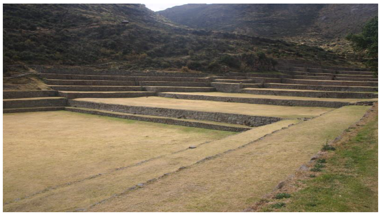
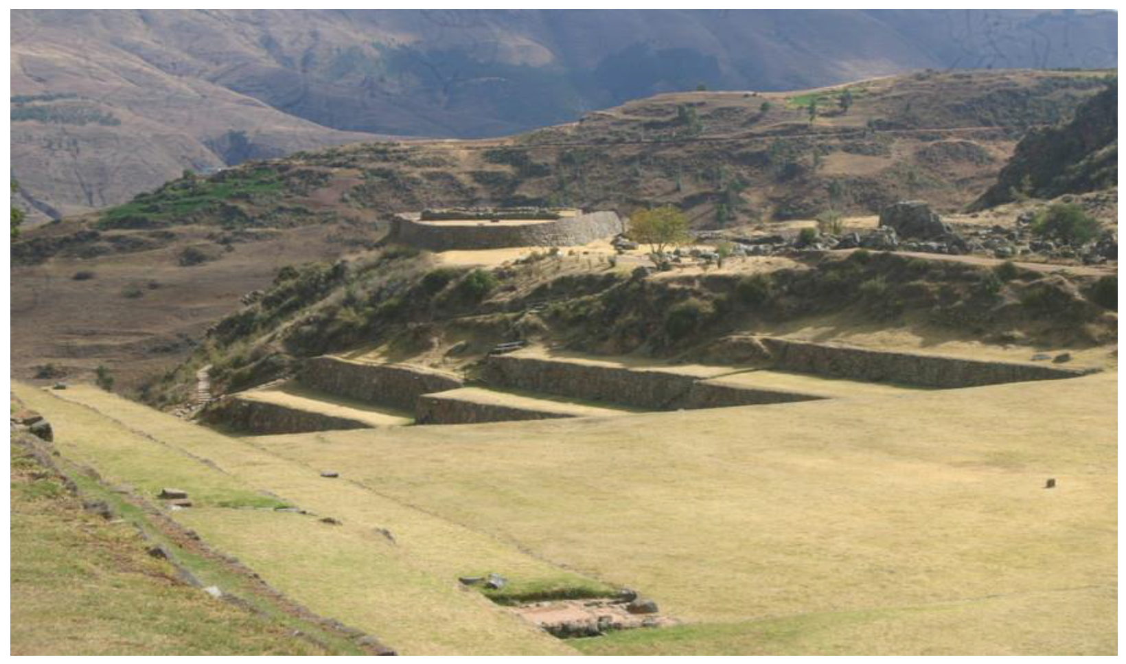
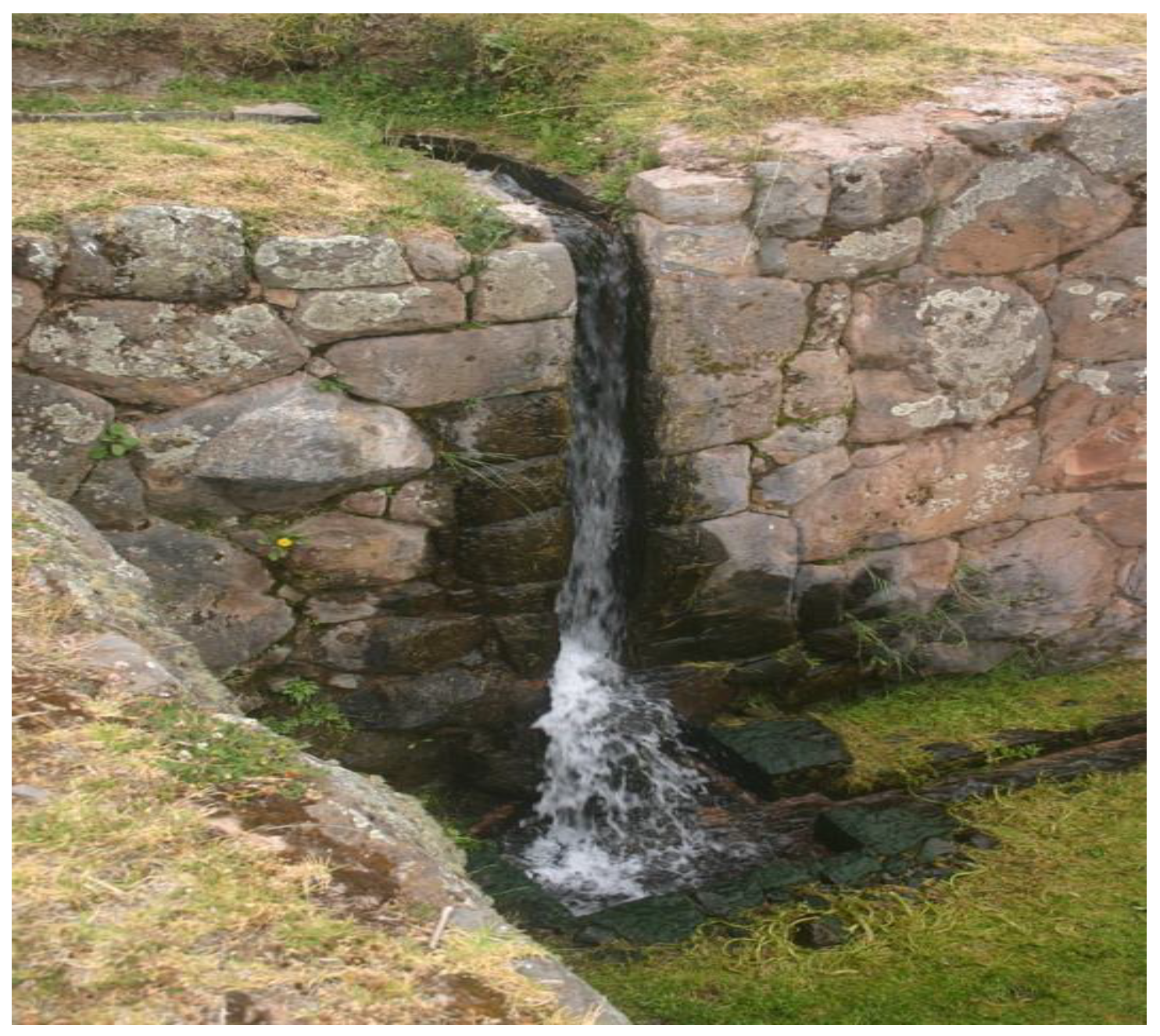
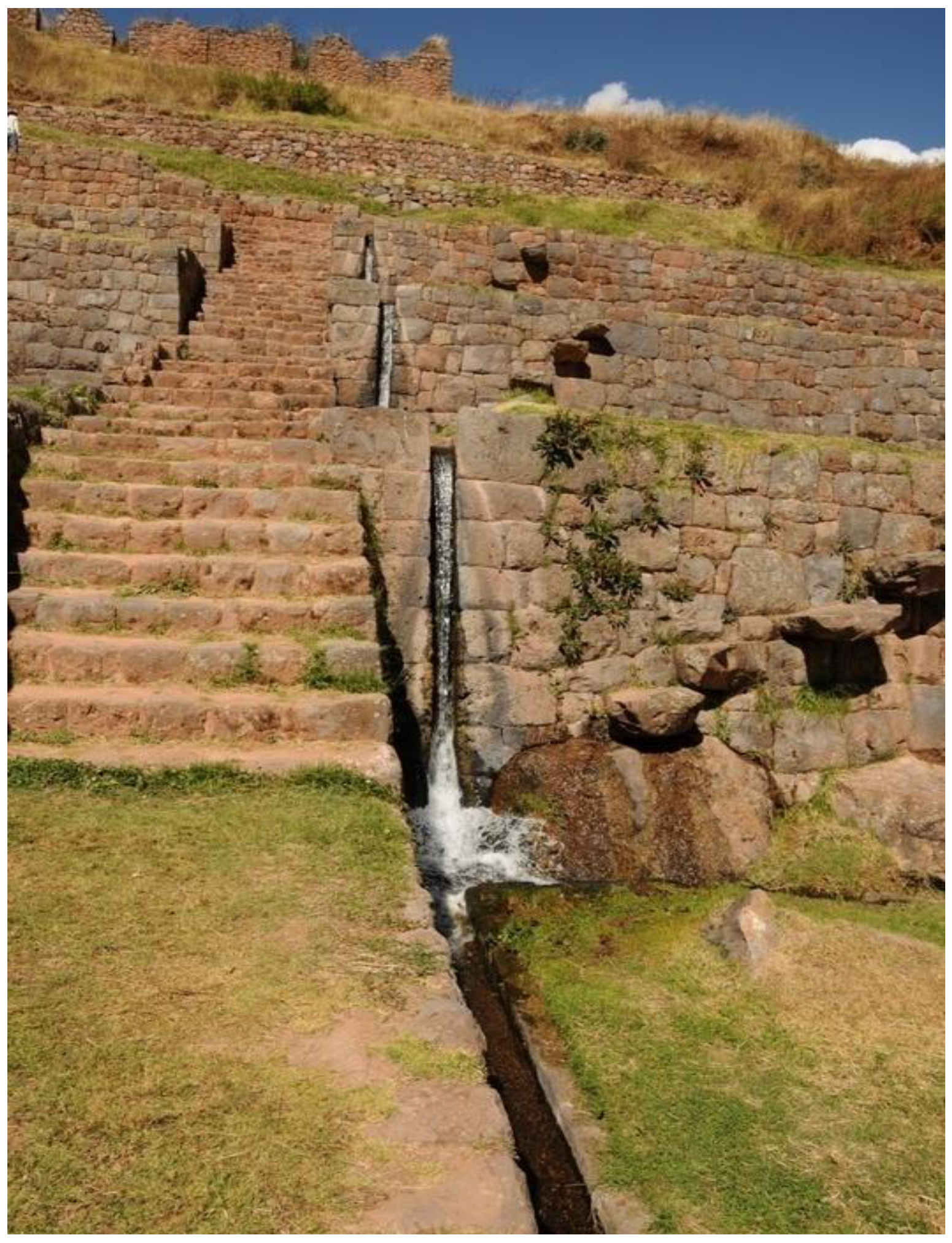
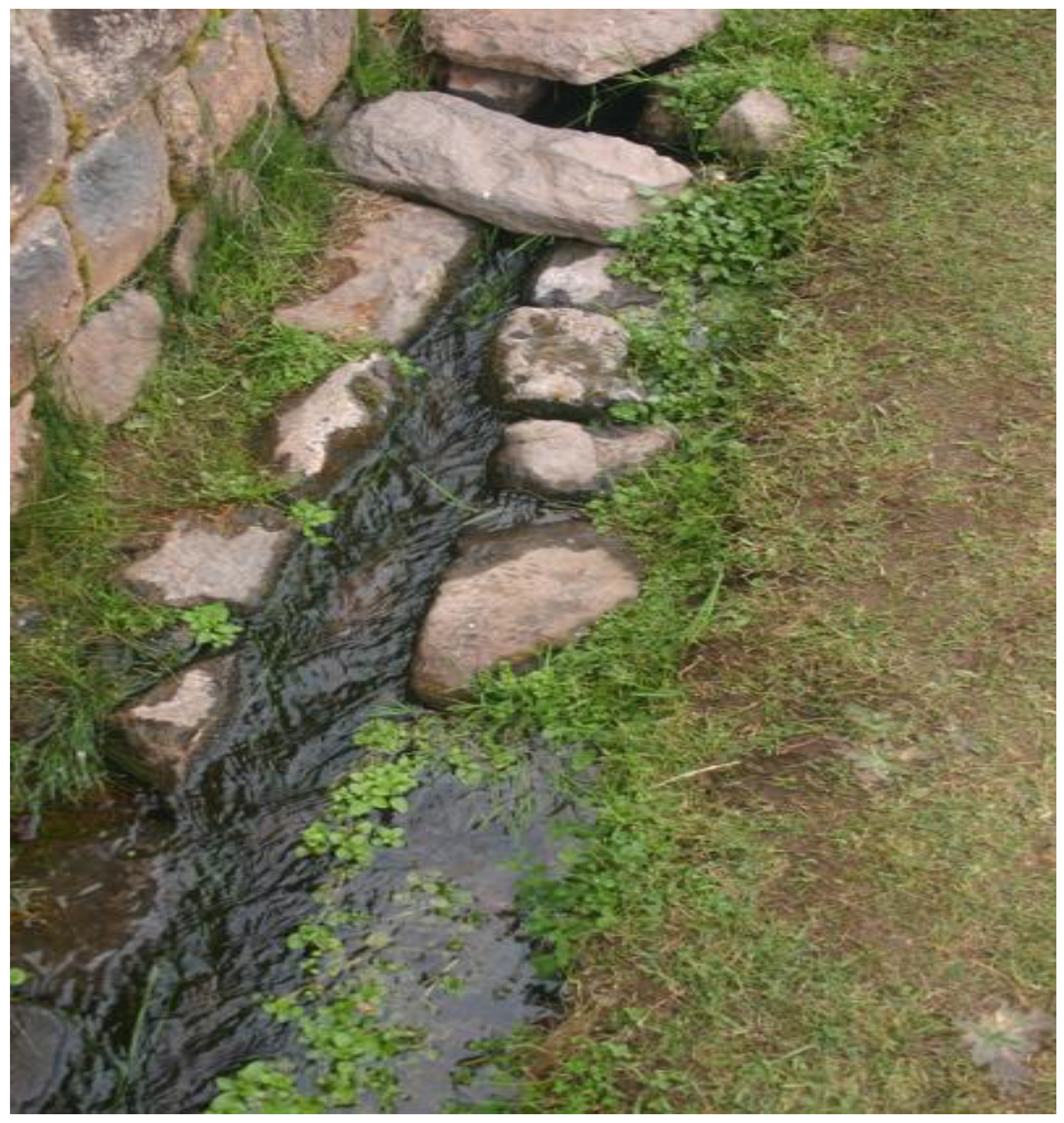
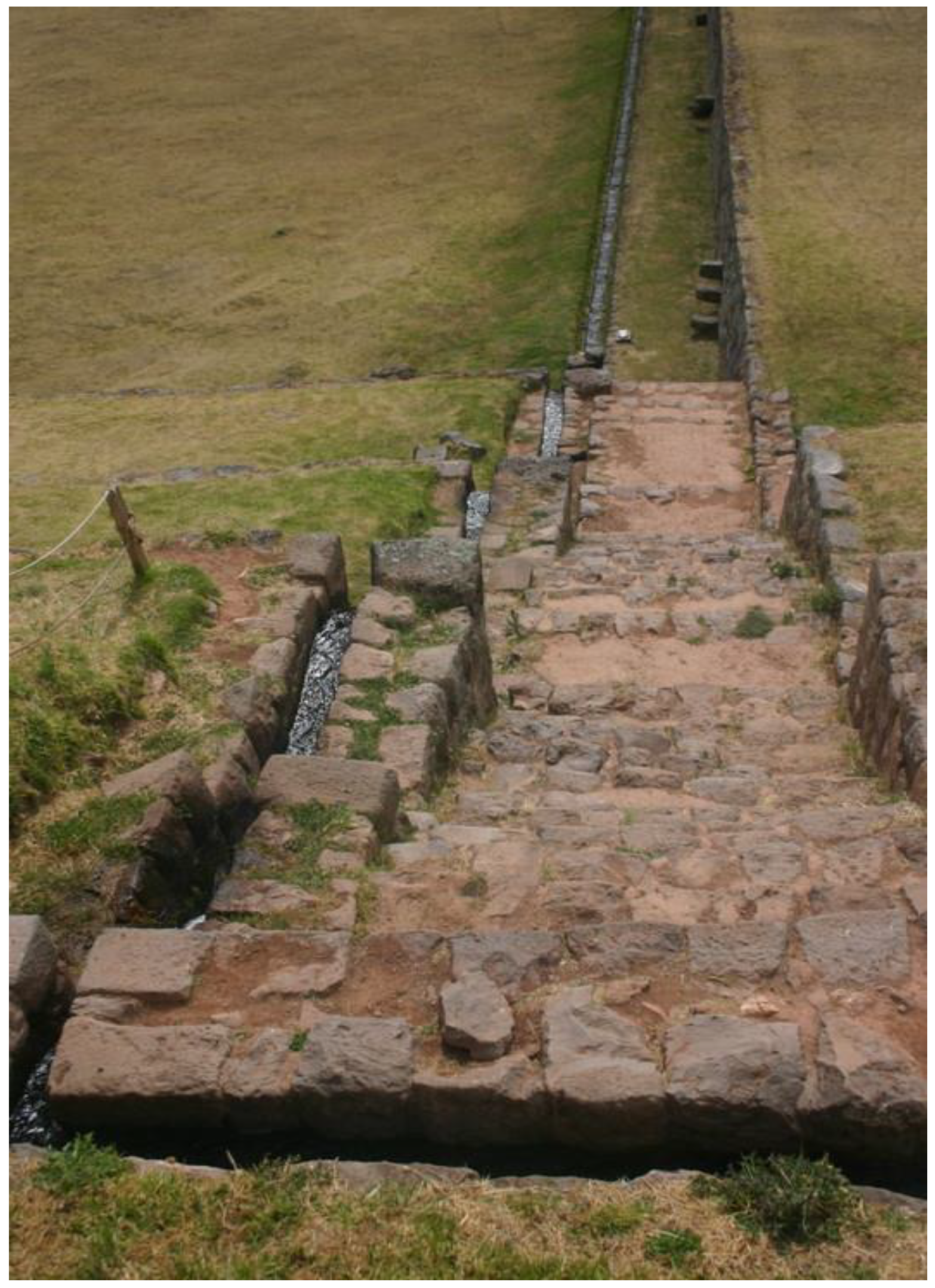
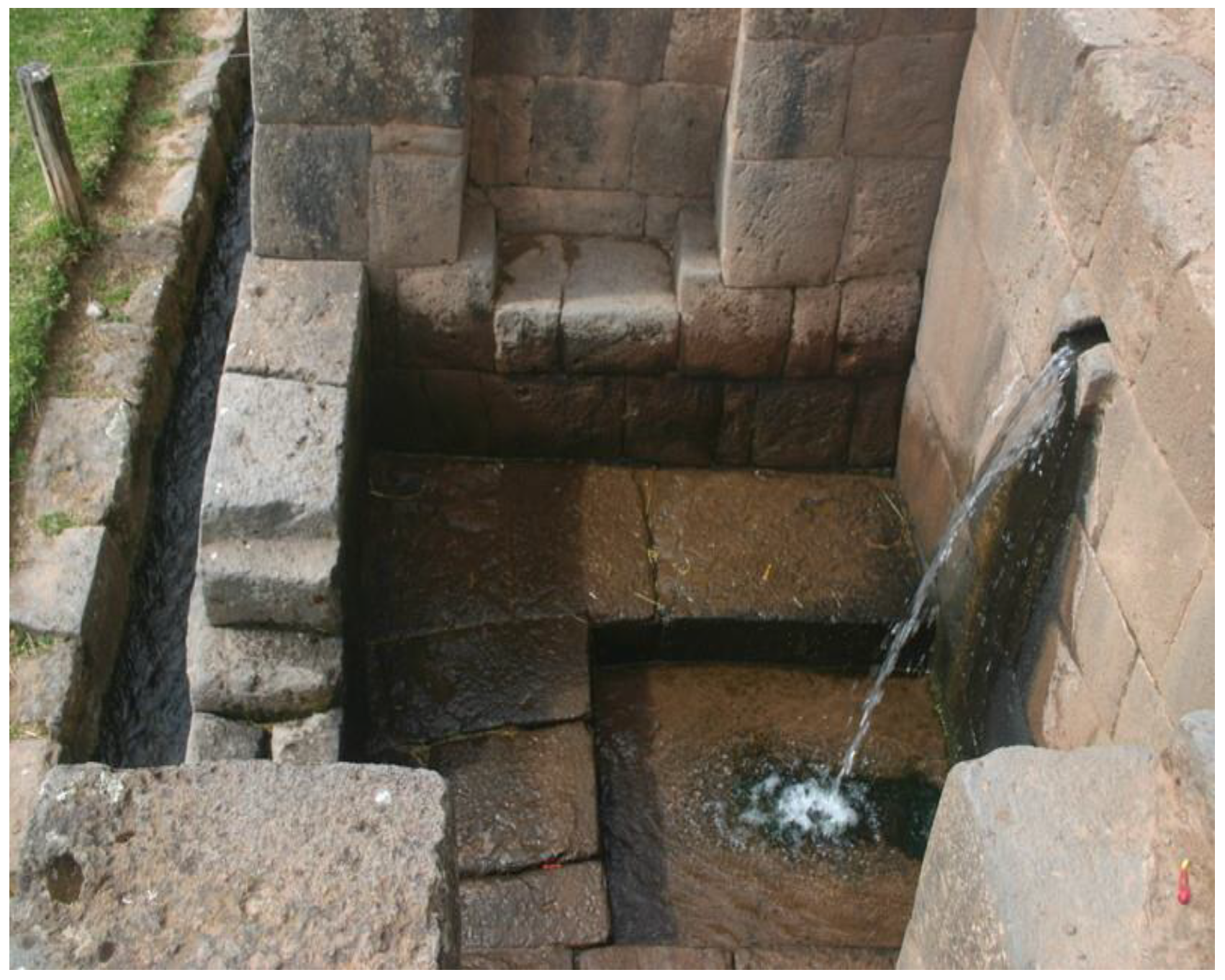
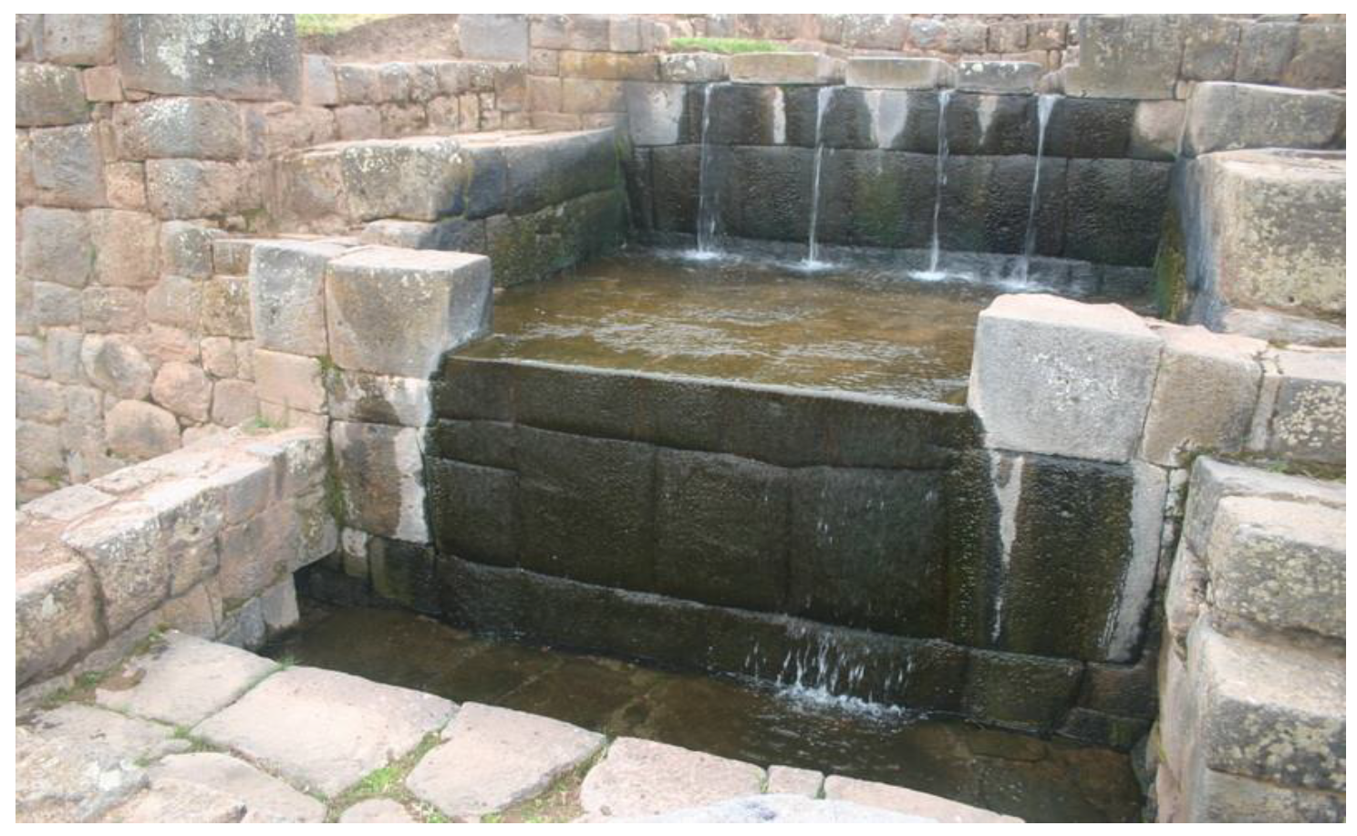
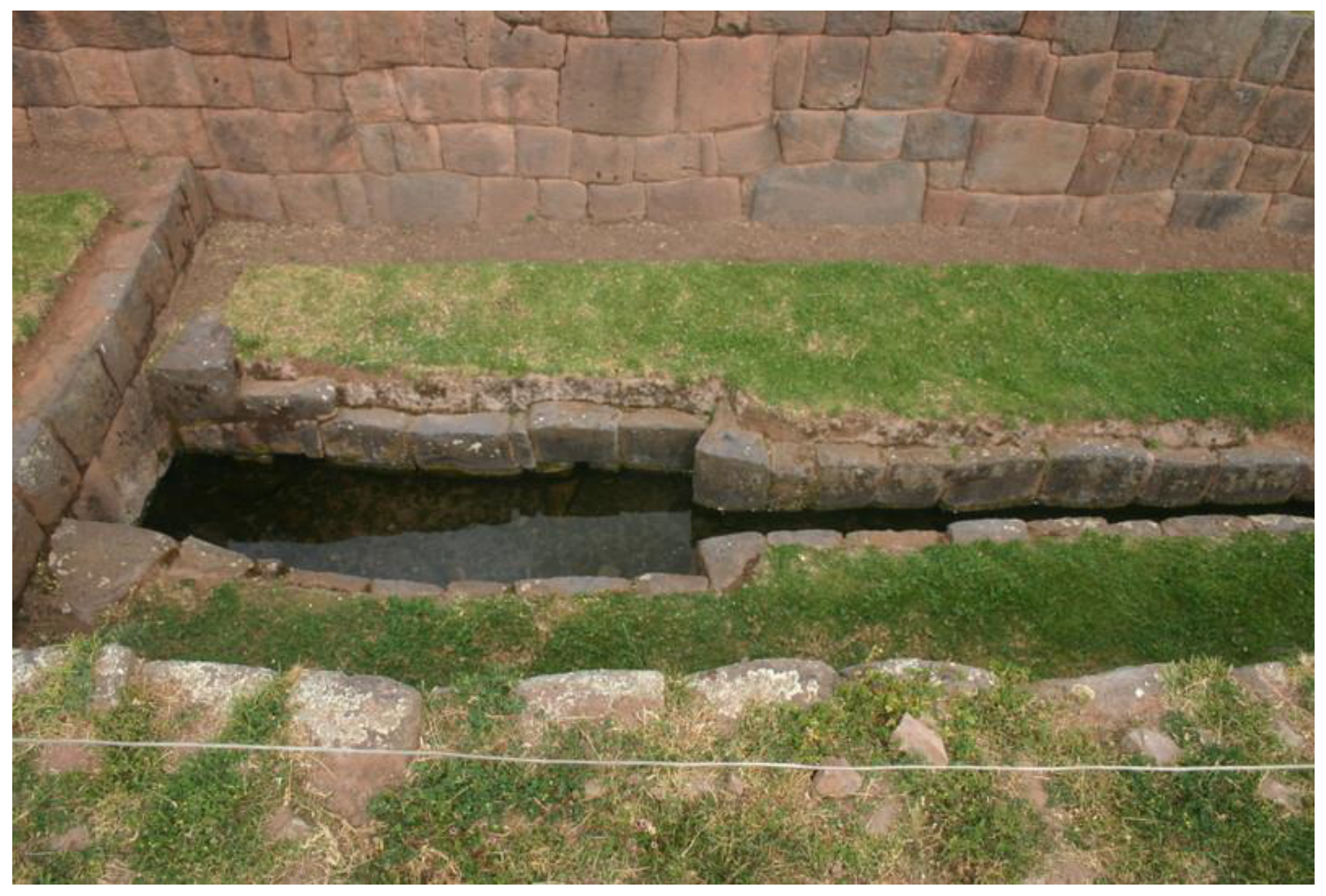
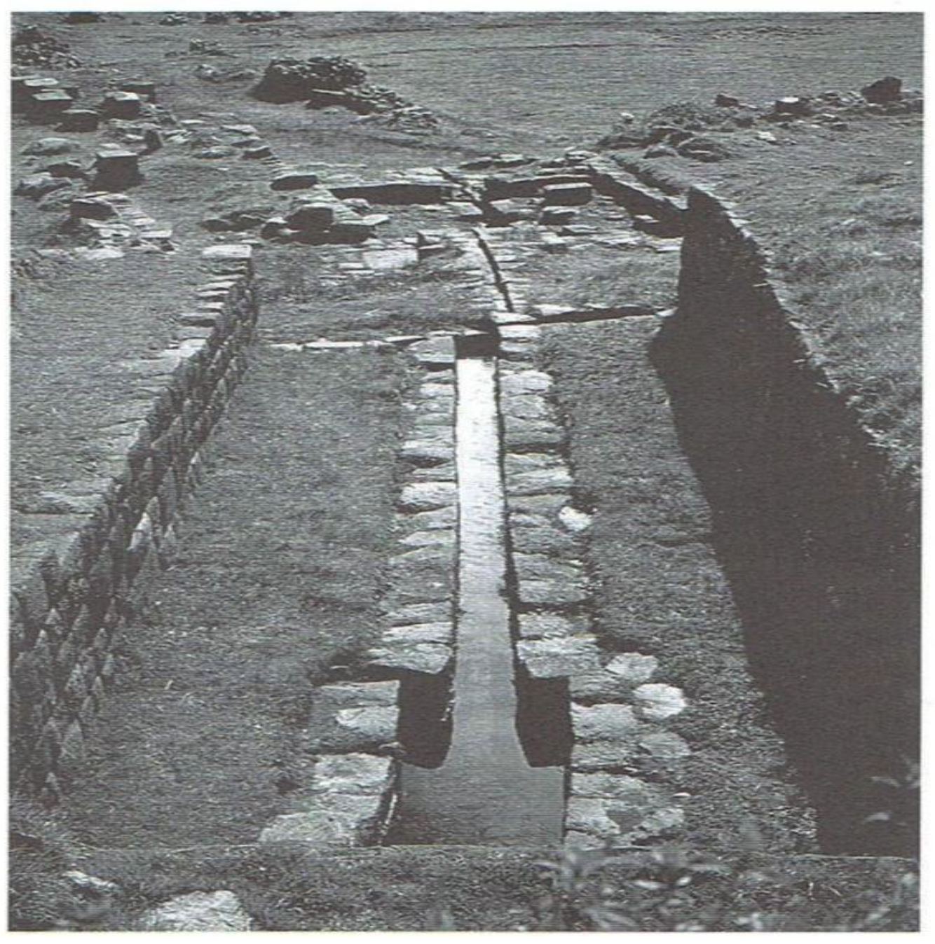
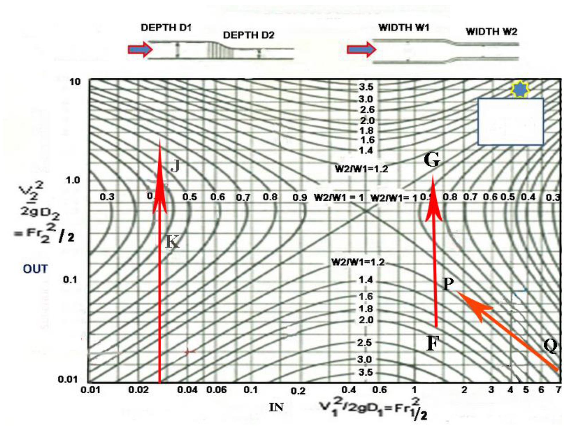
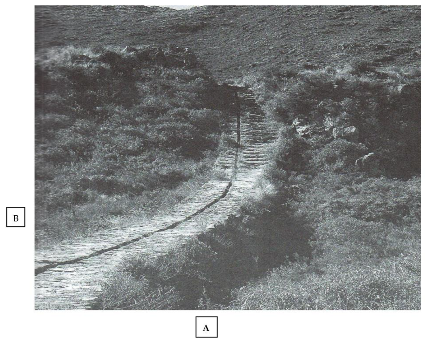
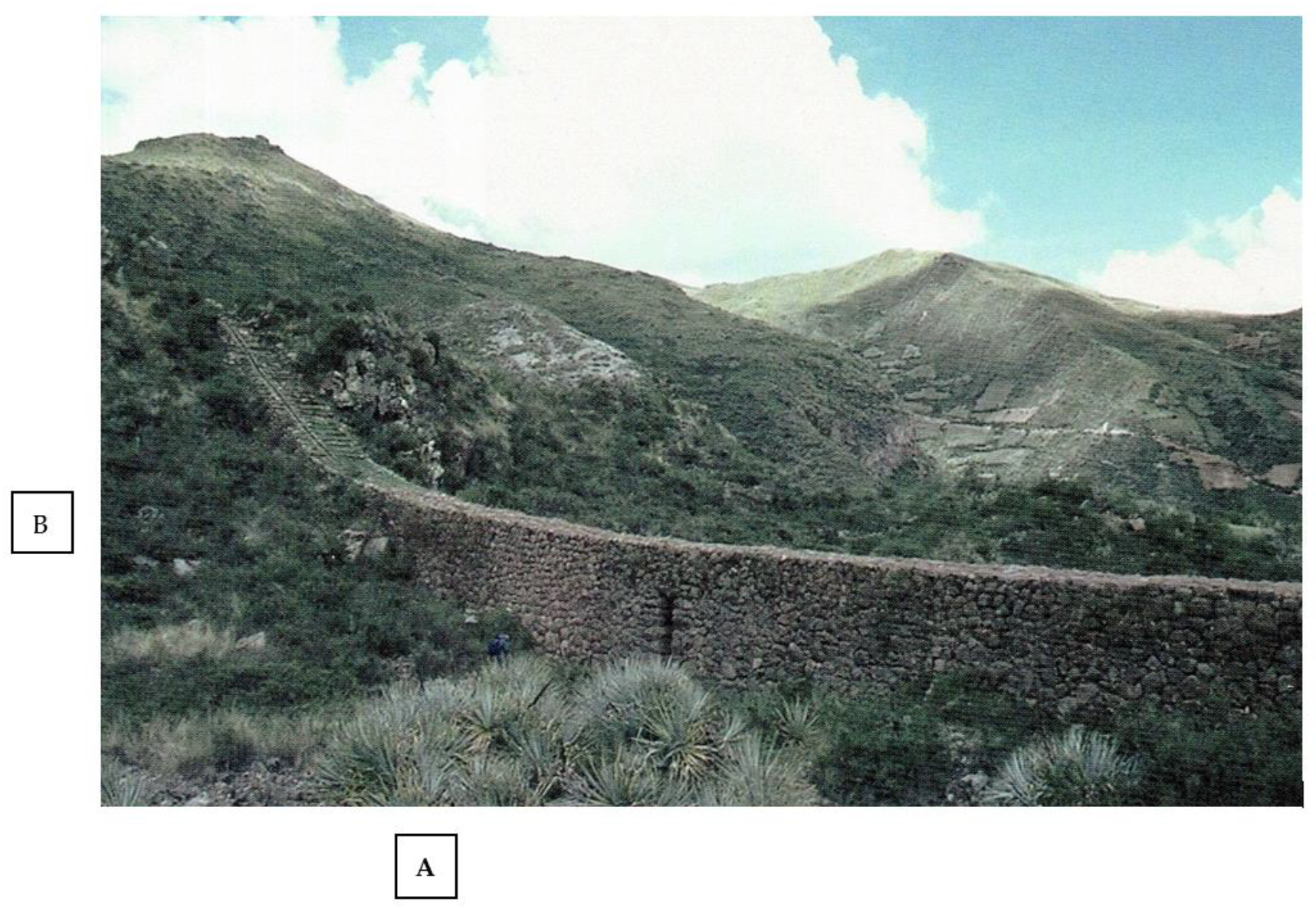
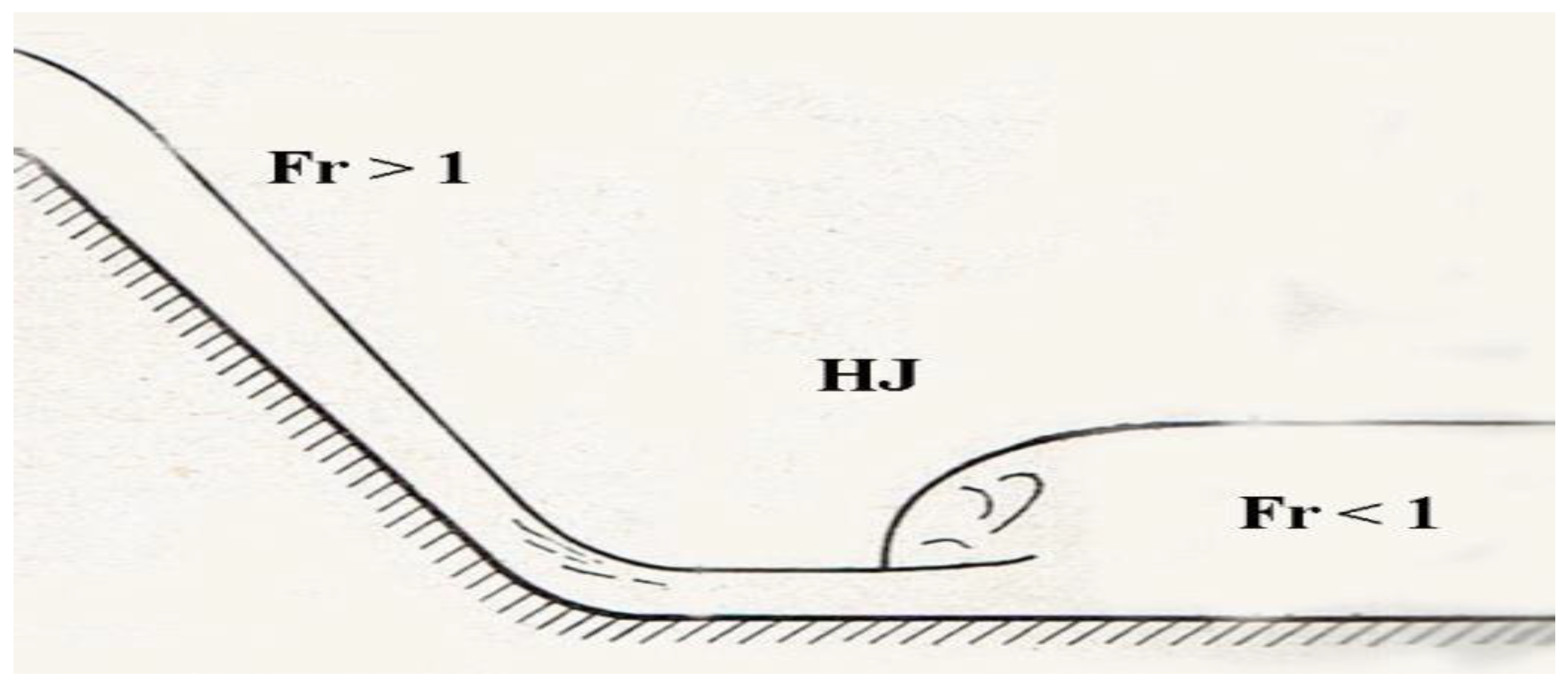
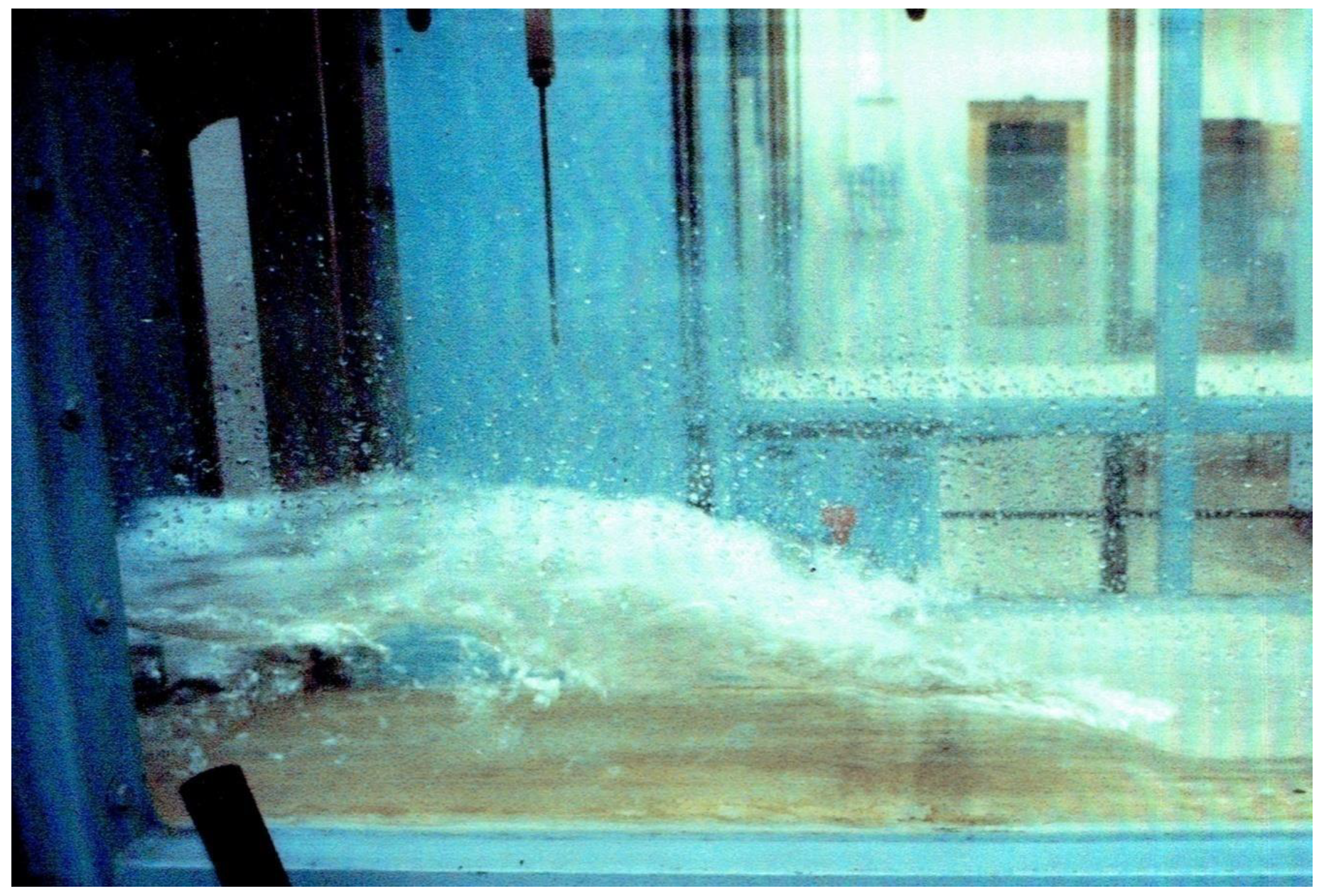
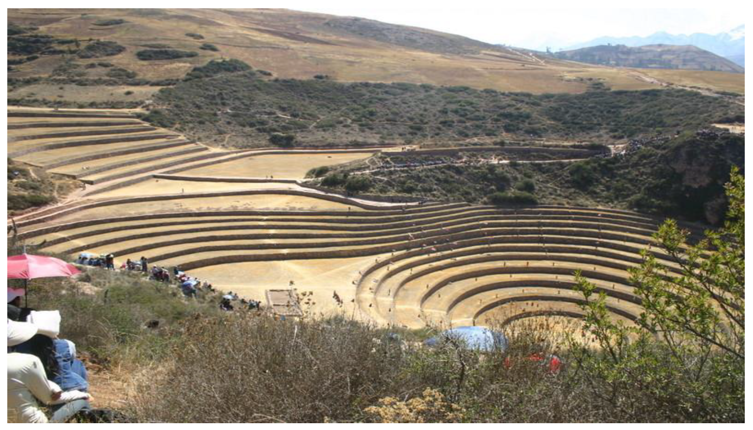
Table 1.
Flow Rate Results for the Major Aqueduct.
| DL (in) | Slope (Degrees) | Velocity (ft/s) | Flow Rate (ft3/s) | Fr1 | h2/h1 | H (ft) | Fr2 |
|---|---|---|---|---|---|---|---|
| 2 | 8.53 | 6.6 | 0.80 | 2.85 | 3.65 | 0.61 | 0.42 |
| 2 | 11.3 | 7.6 | 0.92 | 3.29 | 4.18 | 0.70 | 0.24 |
| 2 | 16.7 | 9.3 | 1.12 | 4.01 | 5.19 | 0.87 | 0.34 |
| 4 | 8.53 | 8.6 | 2.08 | 2.63 | 3.25 | 1.08 | 0.45 |
| 4 | 11.3 | 9.9 | 2.40 | 3.03 | 3.81 | 1.27 | 0.41 |
Publisher’s Note: MDPI stays neutral with regard to jurisdictional claims in published maps and institutional affiliations. |
© 2022 by the author. Licensee MDPI, Basel, Switzerland. This article is an open access article distributed under the terms and conditions of the Creative Commons Attribution (CC BY) license (https://creativecommons.org/licenses/by/4.0/).
Share and Cite
MDPI and ACS Style
Ortloff, C.R. Inka Hydraulic Engineering at the Tipon Royal Compound (Peru). Water 2022, 14, 102. https://doi.org/10.3390/w14010102
AMA Style
Ortloff CR. Inka Hydraulic Engineering at the Tipon Royal Compound (Peru). Water. 2022; 14(1):102. https://doi.org/10.3390/w14010102
Chicago/Turabian StyleOrtloff, Charles R. 2022. "Inka Hydraulic Engineering at the Tipon Royal Compound (Peru)" Water 14, no. 1: 102. https://doi.org/10.3390/w14010102
Note that from the first issue of 2016, this journal uses article numbers instead of page numbers. See further details here.