
Optimization of Hot-Water Drilling in Ice with Near-Bottom Circulation

Polar Research Center, Institute for Polar Science and Engineering, Jilin University, Changchun 130026, China
*
Author to whom correspondence should be addressed.
Water 2022, 14(1), 127; https://doi.org/10.3390/w14010127
Submission received: 14 November 2021
/
Revised: 26 December 2021
/
Accepted: 3 January 2022
/
Published: 5 January 2022
(This article belongs to the Section Hydrogeology)
Abstract
:Hot-water drilling in ice with near-bottom circulation is more advantageous than traditional hot-water drilling with all-over borehole circulation in terms of power consumption and weight. However, the drilling performance of this type of drill has been poorly studied. Initial experiments showed that drilling with single-orifice nozzles did not proceed smoothly. To achieve the best drilling performance, nozzles with different orifice numbers and structures are evaluated in the present study. The testing results show that a single-orifice nozzle with a 3 mm nozzle diameter and a nine-jet nozzle with a forward angle of 35° had the highest rate of penetration (1.7–1.8 m h−1) with 5.6–6.0 kW heating power. However, the nozzles with backward holes ensured a smoother drilling process and a larger borehole, although the rate of penetration was approximately 13% slower. A comparison of the hollow and solid thermal tips showed that under the same experimental conditions, the hollow drill tip had a lower flow rate, higher outlet temperature, and higher rate of penetration. This study provides a prominent reference for drilling performance prediction and drilling technology development of hot-water drilling in ice with near-bottom circulation.
1. Introduction
Currently, hot-water drill systems are effectively used to provide access holes for the observation of ice shelf anisotropy, the recovery of sub-ice seabed samples, the investigation of interior ice structures, video imaging, temperature logging, estimations of distortion inside the ice, assurance of basal sliding speed, clean access to subglacial lakes, and numerous other scientific goals [1,2,3]. In these systems, the hot water required is usually heated at the surface through large boilers, which are then pumped at high pressure through borehole hoses into nozzles to melt the ice. In most cases, an additional pump is installed to pump water from the borehole to the surface tank for recycling. This structure results in traditional hot-water drills being bulky, heavy, and extremely power-hungry.
To reduce the heat losses, weight, and power consumption of the system, it is reasonable to move the heating source from the surface down to the base and circulate hot water in the open loop near the bottom. For this situation, there is no need to utilize long, weighty hoses and high-pressure surface pumps. Furthermore, heat losses in the hot water flow are avoided before they reach the lowest part of the hole.
The first small-diameter ice drilling system with near-bottom hot water circulation, Electrochaude (French translation: Electro-hot), was designed by the Laboratoire de Glaciologie et G’eophysique de l’Environnement in Grenoble, France in the 1980s [4]. The drill housed an electromagnetic pump and filter. Inside the drill, a ceramic tube was placed, comprising a nichrome twisting that warmed with a dispersing power of 1.6 kW. In excess of 1200 m of boreholes were penetrated with Electrochaude in the Blanc, Bossons, Argentiere, Mer de Glace, and Mont de Lans glaciers in the Alps. At the Mer de Glace, the maximum rate of penetration (ROP) of 14 m h−1 was achieved with a 1.2 mm nozzle at the tip; even debris layers were met. The water jet temperature was approximately 30–40 °C. Nevertheless, a few issues were experienced from the power shortages of the drill. Experiments with drilling in ice using hot-water near-bottom circulation were carried out at the Jet Propulsion Laboratory, California Institute of Technology [5], and Stone Aerospace [6]. Both showed a promising outlook of the so-called active heater, a source to melt ice through a hot-water jet nozzle at the drill tip. The active heater formed a melt zone with a parabolic shape in front of the drill, and it penetrated faster through the thick ice than the conventional solid penetration tip (passive heater).
Recently, RECoverable Autonomous Sonde, a new type of hot point, was developed at Jilin University to investigate and sample subglacial lakes in Antarctica [7]. During the experiments, the penetration rate, however, was reduced owing to dust accumulation on the bit while drilling through dirty ice [8]. To solve this problem, an ice drilling system with near-bottom hot-water circulation was considered instead of a solid thermal tip [9]. In the initial experiments at a water flow rate of 3.0 L min−1, the highest ROP of 2.5–3.1 m h−1 was achieved with a nozzle diameter of 3.0 mm. However, because the diameter of the drill is 160 mm, the drilling process under the single-orifice nozzle is very unstable because of the initial tight borehole, resulting in stepped oscillations of the drilling process. The most crucial part of the near-bottom circulation is the nozzle structure/diameter, which determines the speed and spread of the melting process. Thus, to solve the problem of discontinuous penetration, it is necessary to optimize the structure of the drill tip and nozzle that can produce a borehole large enough to enter the drill at once.
Nozzles commonly used in hot-water drilling systems can be divided into two types: single-orifice and multi-orifice nozzles. Traditionally, hot-water drilling systems use a single-orifice nozzle with a high water-flow rate (>10 L min−1) and high injection pressure (1–6 MPa). Taylor experimented with different nozzles and concluded that a single-orifice nozzle is very important in forcing a turbulent stream of water ahead of the advancing nozzle [10]. The maximum ROP was observed when the diameter of the single-orifice nozzle was 3.05 mm at a flow rate ranging from 3.3–10 L min−1 and water temperature of 20–50 °C. Thorsteinsson et al. [11] tested drilling tips with seven 0.8-mm-wide orifices and one with a single 1.5-mm-wide orifice. In both cases, the ROP was similar, but the multi-orifice melting tip appeared to increase the probability of deviations from the vertical drilling direction.
In this study, the influence of multiple water jets and thermal drill tip structures on the ice-melting performance was experimentally studied. Guidelines for choosing a multi-orifice nozzle for thermal ice drilling systems with near-bottom hot-water circulation are proposed.
2. Experimental Methodology
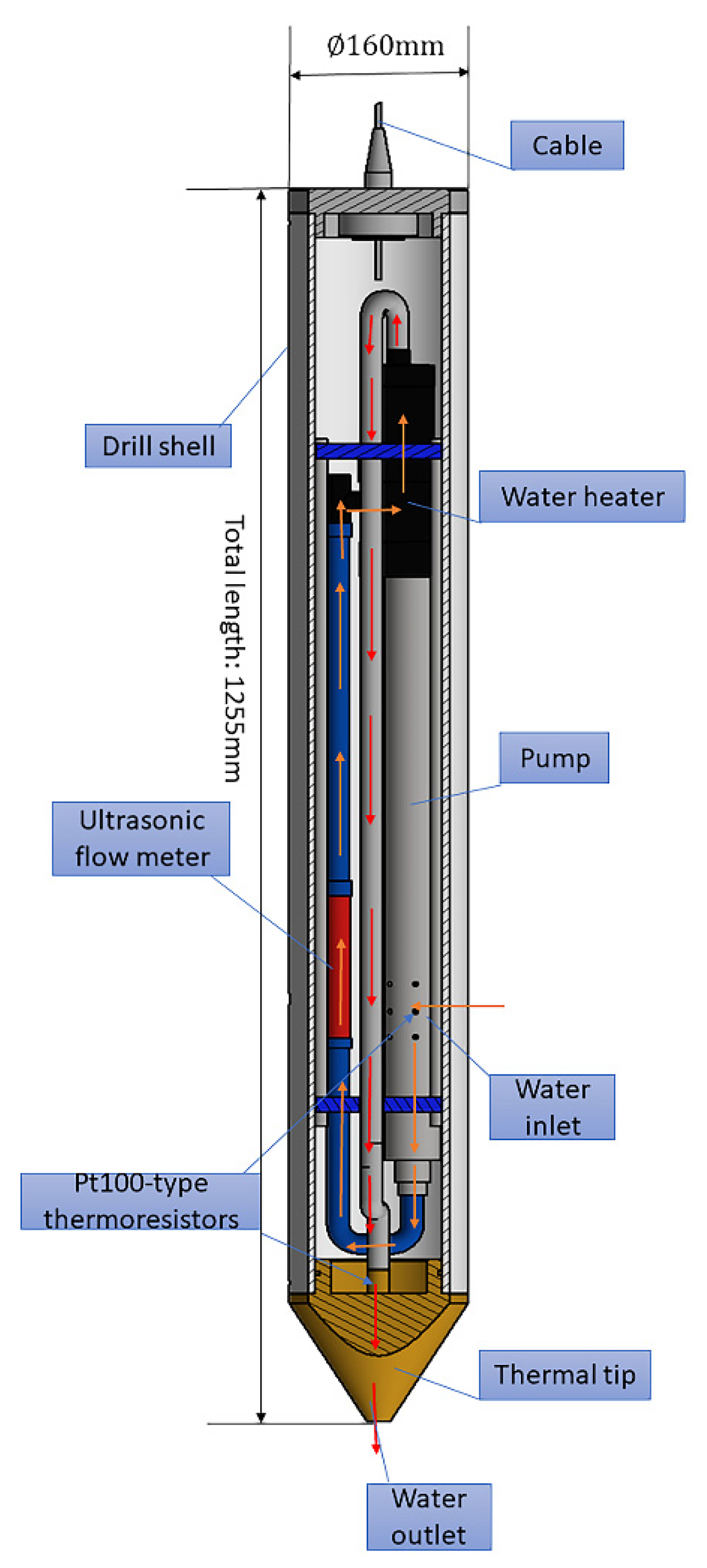
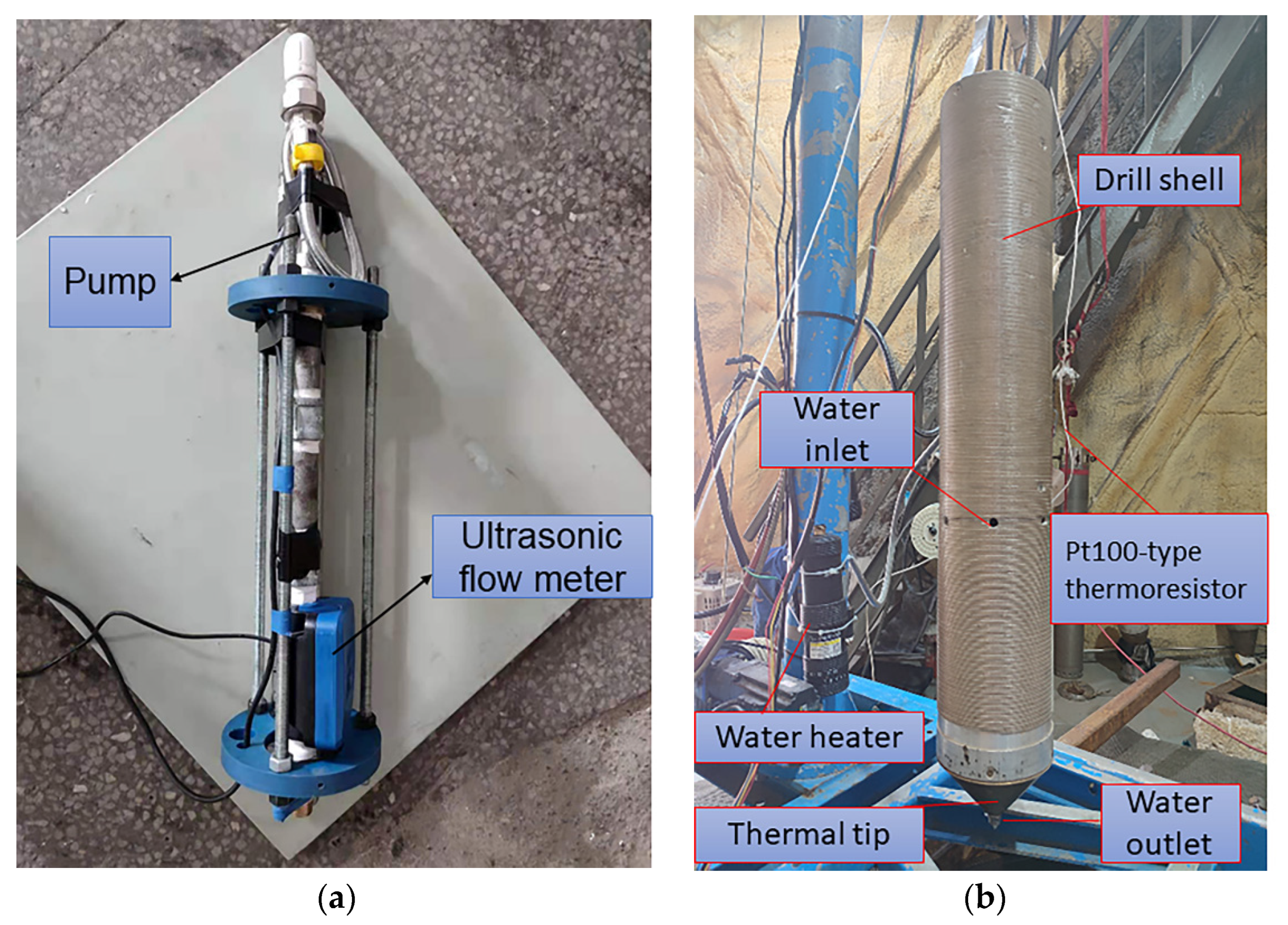
To compare the jet performances of the different nozzles, a prototype hot-water drill with near-bottom circulation and replaceable drill tips and nozzles was developed (Figure 1 and Figure 2). The water heater was KDR-18H with a nickel–chromium wire heating element. We used an ultrasonic flow meter measuring 165 × 67 × 87 mm to meet the system integration requirements. The parameters of the pump are listed in Table 1.
The drill was designed with an open-loop melting unit, and water from the clearance between the drill and the borehole wall was pumped down by a downhole pump into the direct-flow water heater. The hot water, at that point, flows through the drill tip and jets out from the nozzle on the ice face [9]. At the beginning of drilling, a certain amount of tap water is added to the ice well up to the drill pipe inlet. During drilling, the weight on bit (WOB) is regulated by adjusting the frequency of the frequency converter to control the speed of the servo motor rotation. In this control system, there are two control modes of drilling speed: a manual mode and an automatic mode. The automatic mode means that a reference value can be preset for weight on bit. When the WOB changes, the motor speed is adjusted automatically according to the set frequency. Just make sure that the drill tip is in the same position each time drilling starts and that the WOB is modulated in the same manner before drilling starts. When the initial position of the drill tip is correctly adjusted, the weight on bit is set to 20% of the total weight of the drill, and the data acquisition system is started. The water pump is then turned on, and the heater is switched on when the water pump is running properly. When the drill tip is fully in the ice, the WOB setting value is adjusted to 30% of the total weight of the drill to achieve stable drilling. To detect the temperature of the intake water entering the built-in pump and the nozzle ejection temperature, Pt100-type thermoresistors with an accuracy of 0.1 °C (sensor size: ∅3 × 10 mm) were installed at the drill casing inlet and the drill tip outlet to monitor the temperature.
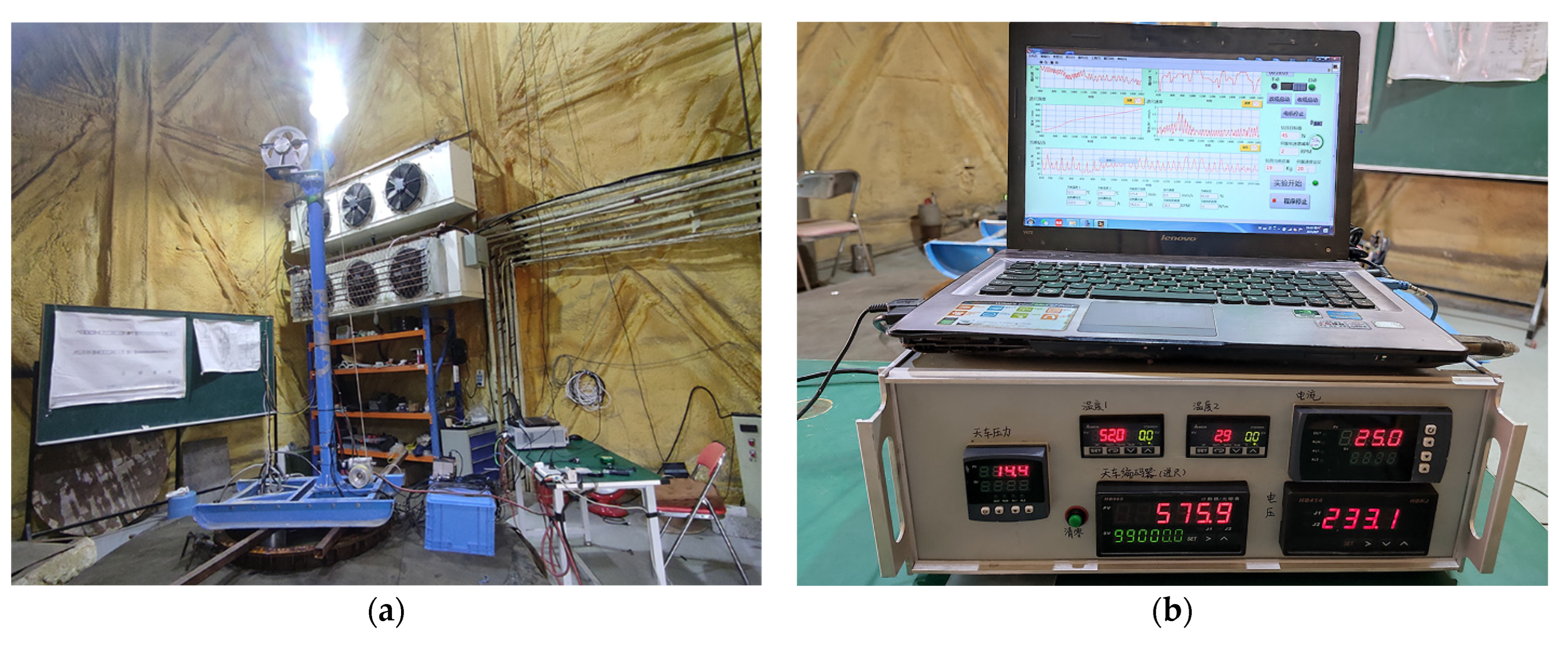
Tests were performed in an ice drill testing facility that permits the testing of various mechanical and thermal ice drills throughout the year [12]. The facility includes an ice well (12.5 m deep and 1 m diameter) with a minimum ice temperature of −30 °C. A testing stand comprising a mast with a frame, a transformer, a winch, and a control system was installed on the top of the ice well (Figure 3). The stand and the monitoring system have been described in detail by Talalay et al. (2021) [9].
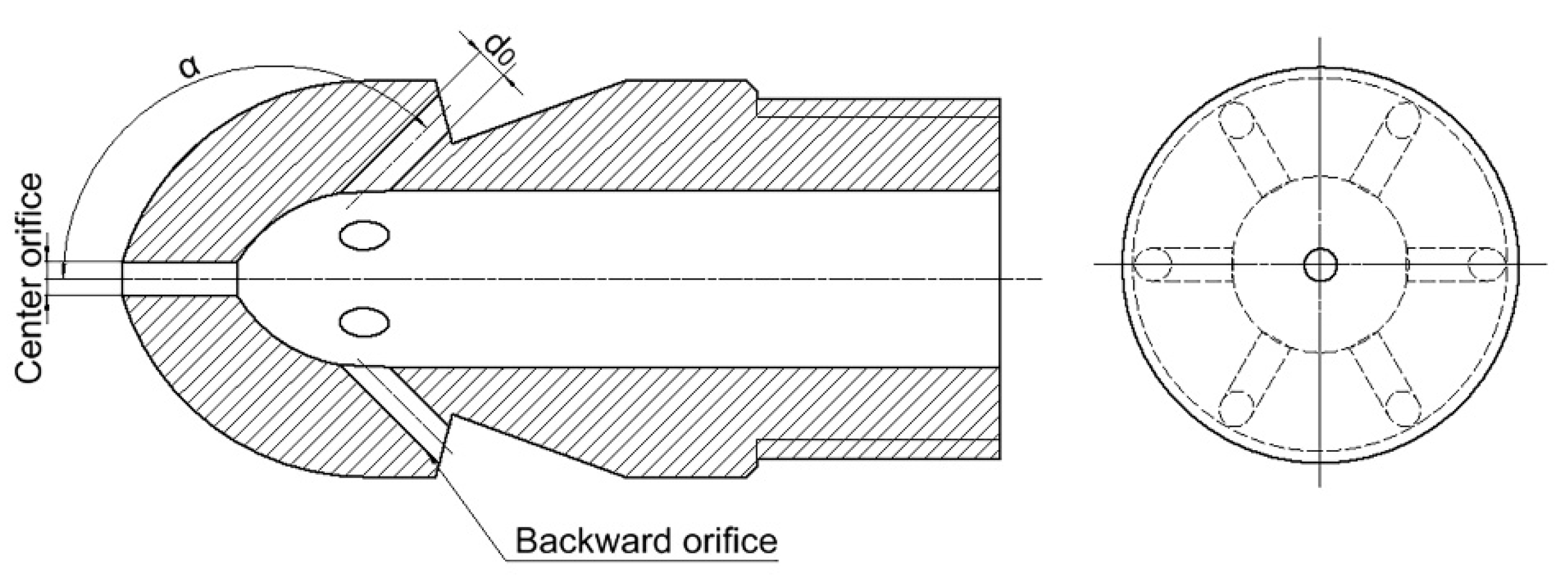
During the experiment, we tested 20 different nozzles (Figure 4 and Figure 5, Table 2) and investigated the influence of several important design features of nozzles on the drilling–melting performance. These include the orifice diameter d0 and the number (index) of the orifices nf + nc + nb, where nf is the number of forward orifices, nc is the number of center orifices, and nb is the number of backward orifices (there was only one center orifice along the axis of the tip). Another important parameter is the angle α between the nozzle axis and the forward or backward orifices (0 < α ≤ 90° for forward orifices and 90 < α < 180° for backward orifices).
To test the influence of the heat transfer area on the efficiency of ice melting, two types of drill tips were designed and tested (Figure 6). One tip has a shape similar to a hollow-ware article with a large inner surface area; another tip was manufactured as a solid piece.
3. Results and Discussion
A total of 60 tests were conducted in the laboratory of the Polar Research Center in Changchun (Figure 7). The penetration ranged from 0.7 to 1.2 m, and the ice temperature was maintained at approximately −20 °C. The power of the water heater was in the range of 5.6–6.0 kW.
3.1. Effect of the Orifice Number and the Forward/Backward Orifice Axial Angle α on the ROP
The angle α of the forwarding orifices primarily decides the extent of jet velocity in different directions. Thus, this angle affects the jet coverage area and jet distance. If the axial angle is too large (45°), the jets are extremely scattered and the jet distance is short. In this case, the higher the number of nozzle orifices, the lower the melting efficiency. When the axial angle was small (15°) and the number of nozzle orifices was also small, the jet flow was more concentrated, resulting in the highest ROP. Under the experimental conditions of this study, we determined the optimum orifice number and axial angle for multi-orifice nozzle #6, with indices 8 + 1 + 0 and α = 35° (Figure 8).
The ROP of nozzles with backward orifices was slower than that of nozzles with only forward orifices. Nozzle #19, with six backward orifices, had a faster ROP than nozzles with three (#17) and four (#18) backward orifices (Figure 9). The results show that although the flow rate increases with the number of backward orifices, the jet velocity does not increase significantly, and in some of them, it actually decreases.
Some portion of the energy from nozzles with backward orifices is applied to expand the hole, so the diameter of the borehole drilled by these nozzles is larger than that of the other nozzles. Nozzles with a small number of orifices produced very uneven borehole walls, and there were many narrow parts around the borehole (Figure 10). The following causes may be responsible for uneven borehole shapes. On the one hand, with a larger number of backward orifices, the distribution of jet energy is more uniform, and the borehole shape is even more uniform. On the other hand, the poor thermal conductivity of the drill tip may also cause the irregular shape of the drill hole.
The change in the flow rate and outlet water temperature during drilling for nozzles with backward orifices is shown in Figure 11a,c. The higher the number of backward orifices, the higher the flow rate. Because of the use of instantaneous heating, the higher the flow rate, the lower the outlet temperature. Consistent with the results of the nozzles having backward orifices, there is no obvious correlation between the jet velocity and the drilling speed. Although the decrease in the diameter of the orifice leads to an increase in jet velocity, the increase in jet velocity also leads to a decrease in the water heating temperature. That is illustrated by the curves in Figure 11.
3.2. Effect of the Orifice Diameter of the Single-Orifice Nozzle (0 + 1 + 0) on the ROP
The diameter of the forward orifice straightforwardly decides the energy conveyed to the ice face. Therefore, it would be interesting to study the influence of the orifice diameter of the single-orifice nozzle on the ice-melting efficiency. When the diameter of the orifice is too large, the energy yield from a single jet is feeble and generally limited. Thus, the drill cannot provide a sufficiently high ROP. With a decreased orifice diameter, the jet flow increases such that the effect of the jet is stronger and the ice-melting capacity is improved. However, a small orifice diameter results in severe pressure loss. Furthermore, the power of the instantaneous heater is constant, and the temperature of the hot water decreases with an increasing water flow rate, as shown in Figure 12. The optimal orifice diameter was 3.0 mm, at which the highest ROP of 1.78 m h−1 was reached (Figure 13).
3.3. Effect of the Nozzle Type on the ROP
The number and arrangement of the orifices are important factors that influence the speed of jet ice melting. The nozzle structure directly affects the flow rate, the temperature, the outlet pressure of the water jet, and jet velocity, thereby affecting the intensity of convective heat transfer at the ice–water interface. Figure 13 presents the experimental results of drilling with different types of nozzles (single-orifice nozzles and multi-orifice nozzles with downward and backward orifices) that enable the highest ROP in their own classes. Drilling results with a spiral nozzle were also added to the graph. However, because of the special injection form of the spiral nozzle and its very slow ROP, the curve of jet velocity was not added. There was no significant difference in jet velocity in the other nozzles. Nozzles #6 and #15 were practically identical in terms of ROP, while the ROP of nozzle #19, with backward orifices, was slightly lower. Spiral nozzle #20 exhibited the worst performance. Except for nozzle #19, which could maintain a constant speed during drilling, the penetration of other types of nozzles was not stable (Figure 12b).
To estimate the thermal efficiency of each nozzle, an energy balance formula at the bottom of the borehole was used. The thermal energy imparted by the hot water balanced by that required to melt a given volume of ice can be written as
where is the mass flow through the drill tip; is the heat capacity of water at constant pressure (4190 J kg−1 K−1); Tw is the temperature at the drill tip; Tf is the temperature of the water after equilibrium is reached in the borehole; is the ice melting mass at the bottom of the bore; is the temperature of the ice; is the heat capacity of water at constant pressure (2100 J kg−1 K−1).
The results of thermal efficiency estimations of different nozzle types, according to Equation (1), are shown in Figure 12a.
3.4. Effect of the Drill Tip on the ROP
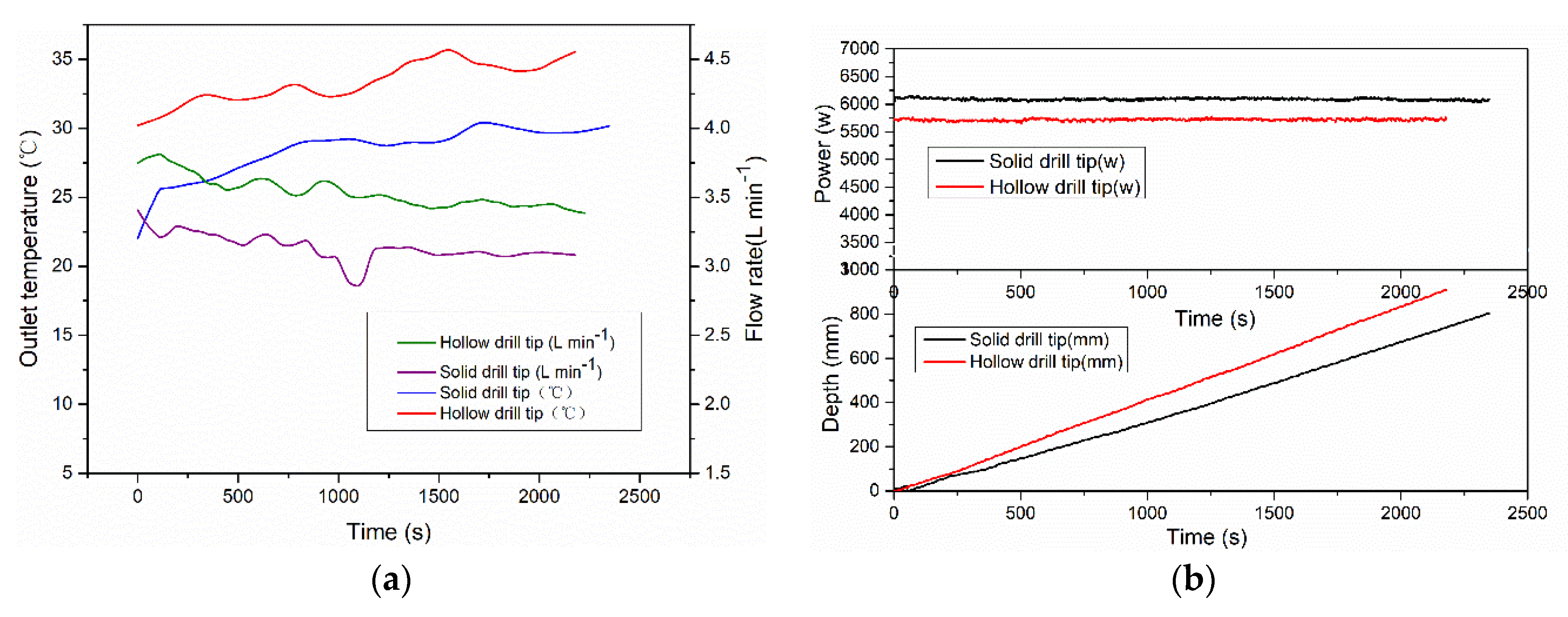
To accelerate the heat transfer rate between the sidewall of the drill tip and the circulating water in the borehole and thus increase the drill tip drilling ability, the performances of the hollow and solid drill tips were compared experimentally (two types of drill tips are shown in Figure 6). Under the same experimental conditions, the hollow drill tip had a lower flow rate, higher outlet temperature (Figure 14a), and higher ROP (Figure 14b). The most likely reason is that the hollow tip increases the heat transfer rate between the tip wall and the ice because of the thinning of the wall (5 mm); the existence of the drill tip cavity slows down the heat loss of the circulating water. In addition, cold spots may occur during drilling due to different drill tip designs, resulting in impediments to progress [10]. A hollow drill tip can transfer heat through the sidewall to the ice, unlike a solid drill tip, and is important for removing unpredictable cold spots. Because of the use of opaque ice, it was not possible to see the actual drilling process.
4. Conclusions
Hot-water drilling with near-bottom circulation is a type of ice drilling technology. The drills provide better performance in terms of both the number of boreholes and the portability of equipment than traditional hot-water drills. The critical components of this technology are the structure of the nozzle and the drill tip. Owing to high-pressure jets, single-orifice nozzles are most commonly used in traditional hot-water drilling systems.
In the present study, the physical parameters (diameter, number, and axial angle of the orifices) of the nozzle that affect the ice-melting properties of the drill tip were investigated. According to our experiments, the ice-melting efficiency of single-orifice and multi-orifice nozzles with forward orifices is much higher than that of those with backward orifices. Under the experimental conditions accepted in this study, the optimal multi-orifice nozzle with index 8 + 1 + 0 had eight downward orifices with an axial angle of 35°. For a single-orifice nozzle, the optimal orifice diameter is 3.0 mm. However, drilling large-diameter holes (160 mm) with these nozzles is unstable. Nozzles with backward orifices can be used to effectively solve this problem. The larger the number of backward orifices, the more even the shape of the borehole. Although the ROP with this nozzle is 13% lower than that of the fastest nozzle with downward orifices, it would be a better choice because of the smoother drilling process. To increase the heat transfer efficiency between the drill and the ice face, the use of a hollow drill bit is recommended.
Our findings could not provide a universal model for nozzles with each diameter/number/angle orifice. Notwithstanding, they are a noticeable reference for the forecast of penetrating performance in glaciers and ice sheets using hot-water drills with near-bottom circulation. To study the process qualitatively, visualization experiments with transparent ice will be conducted in the near future. In addition, mathematical modeling of hot-water drilling with near-bottom circulation is underway. The internal reasons affecting the ROP are complex and need to be further studied with the help of the forthcoming mathematical model.
Author Contributions
Conceptualization, G.Z. and P.G.T.; methodology, G.Z. and P.G.T.; software, G.Z. and Y.L.; validation, G.Z.; formal analysis, X.F.; investigation, G.Z. and P.G.T.; data curation, G.Z.; writing—original draft preparation, G.Z. and P.G.T.; writing—review and editing, G.Z. and P.G.T.; visualization, Y.C.; supervision, X.F. and N.Z.; project administration, T.W.; funding acquisition, P.G.T. All authors have read and agreed to the published version of the manuscript.
Funding
This research was funded by the National Natural Science Foundation of China (Nos. 41941005, 51374258, and 51504046). The APC was funded by the Program for Changjiang Scholars and Innovative Research Teams at the University of China (No. IRT13043).
Institutional Review Board Statement
Not applicable.
Informed Consent Statement
Not applicable.
Data Availability Statement
Not applicable.
Acknowledgments
We are grateful to Yang Y., Li Y., Sysoev M. for useful suggestions and help in testing preparations. We would like to acknowledge the anonymous reviewers who played a significant role in shaping and improving the manuscript.
Conflicts of Interest
The authors declare no conflict of interest.
References
- Makinson, K.; Anker, P.G.D. The BAS ice-shelf hot-water drill: Design, methods and tools. Ann. Glaciol. 2014, 55, 44–52. [Google Scholar] [CrossRef] [Green Version]
- Lutz, F.; Eccles, J.; Prior, D.J.; Craw, L.; Fan, S.; Hulbe, C.; Forbes, M.; Still, H.; Pyne, A.; Mandeno, D. Constraining Ice Shelf Anisotropy Using Shear Wave Splitting Measurements from Active-Source Borehole Seismics. J. Geophys. Res. Earth Surf. 2020, 125, 1–18. [Google Scholar] [CrossRef]
- Miles, K.E.; Miles, E.S.; Hubbard, B.; Quincey, D.J.; Rowan, A.V.; Pallett, M. Instruments and methods: Hot-water borehole drilling at a high-elevation debris-covered glacier. J. Glaciol. 2019, 65, 822–832. [Google Scholar] [CrossRef] [Green Version]
- Rado, C.; Girard, C.; Perrin, J. Electrochaude: A self-flushing hot-water drilling apparatus for glaciers with debris. J. Glaciol. 1987, 33, 236–238. [Google Scholar] [CrossRef] [Green Version]
- Zimmerman, W.; Bonitz, R.; Feldman, J. Cryobot: An Ice Penetrating Robotic Vehicle for Mars and Europa. In Proceedings of the IEEE Aerospace Conference, Big Sky, MT, USA, 10–17 March 2001; Volume 1, pp. 311–323. [Google Scholar]
- Stone, W.; Hogan, B.; Siegel, V.; Harman, J.; Flesher, C.; Clark, E.; Pradhan, O.; Gasiewski, A.; Howe, S.; Howe, T. Project VALKYRIE: Laser-Powered Cryobots and Other Methods for Penetrating Deep Ice on Ocean Worlds. In Outer Solar System; Springer: Cham, Switzerland, 2018; pp. 47–165. [Google Scholar]
- Talalay, P.G.; Zagorodnov, V.S.; Markov, A.N.; Sysoev, M.A.; Hong, J. Recoverable autonomous sonde (RECAS) for environmental exploration of Antarctic subglacial lakes: General concept. Ann. Glaciol. 2014, 55, 23–30. [Google Scholar] [CrossRef] [Green Version]
- Li, Y.; Talalay, P.G.; Sysoev, M.A.; Zagorodnov, V.S.; Li, X.; Fan, X. Thermal Heads for Melt Drilling to Subglacial Lakes: Design and Testing. Astrobiology 2020, 20, 142–156. [Google Scholar] [CrossRef] [PubMed]
- Talalay, P.G.; Zhao, G.; Gong, D.; Hong, J.; Fan, X.; Li, Y.; Sysoev, M.A. Ice drilling system with near-bottom hot water circulation. Polar Sci. 2021, 28, 100676. [Google Scholar] [CrossRef]
- Taylor, A. Hot water drill for temperate ice. In Proceedings of the Second International Workshop/Symposium on Ice Drilling Technology, Calgary, AB, Canada, 30–31 August 1982; pp. 105–117. [Google Scholar]
- Thorsteinsson, T.; Elefsen, S.O.; Gaidos, E.; Lanoil, B.; Johannesson, T.; Kjartansson, V.; Marteinsson, V.P.; Stefansson, A.; Thorsteinsson, T. A hot water drill with built-in sterilization: Design, testing and performance. Jokull 2007, 57, 71–82. [Google Scholar]
- Wang, R.; Liu, A.; Sun, Y.; Cao, P.; Fan, X.; Talalay, P. Ice drill testing facility. Cold Reg. Sci. Technol. 2018, 145, 151–159. [Google Scholar] [CrossRef]
Figure 1.
A 3D model of the hot-water drill prototype with near-bottom circulation.

Figure 2.
The internal (a) and external (b) structures of the drill assembly.

Figure 3.
Overview of the experimental platform (a) and the control system (b).

Figure 4.
Schematic of multi-orifice nozzle #19 (0 + 1 + 6).

Figure 5.
Nozzles used in the experiments: (a) photograph showing all tested nozzles; (b) water jet shape of the nozzle #13; (c) photograph showing the backward orifices in the nozzles.
Figure 5.
Nozzles used in the experiments: (a) photograph showing all tested nozzles; (b) water jet shape of the nozzle #13; (c) photograph showing the backward orifices in the nozzles.

Figure 6.
The 3D models of the drill tips used in the experiments: (a) hollow thermal tip; (b) solid thermal tip.
Figure 6.
The 3D models of the drill tips used in the experiments: (a) hollow thermal tip; (b) solid thermal tip.

Figure 7.
Test overview: (a) drill before drilling begins; (b) the ice well after tests.

Figure 8.
Average ROP vs. the orifice number of nozzles.

Figure 9.
Penetration curves of the nozzles with backward orifices: (a) flow rate vs. time; (b) jet velocity vs. time; (c) temperature vs. time; (d) depth vs. time.
Figure 9.
Penetration curves of the nozzles with backward orifices: (a) flow rate vs. time; (b) jet velocity vs. time; (c) temperature vs. time; (d) depth vs. time.

Figure 10.
Borehole shape obtained by drilling with different nozzles.

Figure 11.
Graphs of drilling parameters of single-orifice nozzles with different orifice diameters: (a) flow rate vs. time; (b) jet velocity vs. time; (c) temperature vs. time; (d) rate of penetration vs. time.
Figure 11.
Graphs of drilling parameters of single-orifice nozzles with different orifice diameters: (a) flow rate vs. time; (b) jet velocity vs. time; (c) temperature vs. time; (d) rate of penetration vs. time.

Figure 12.
Results of comparison between nozzles of different types: (a) average efficiency vs. nozzle type; (b) penetration curves.
Figure 12.
Results of comparison between nozzles of different types: (a) average efficiency vs. nozzle type; (b) penetration curves.

Figure 13.
Drilling parameters comparison between nozzles of different types: (a) flow rate vs. time; (b) jet velocity vs. time; (c) temperature vs. time; (d) rate of penetration vs. time.
Figure 13.
Drilling parameters comparison between nozzles of different types: (a) flow rate vs. time; (b) jet velocity vs. time; (c) temperature vs. time; (d) rate of penetration vs. time.

Figure 14.
Results of comparison testing of the hollow drill tip and the solid drill tip: (a) outlet temperature and flow rate vs. time; (b) penetration depth and power vs. time.
Figure 14.
Results of comparison testing of the hollow drill tip and the solid drill tip: (a) outlet temperature and flow rate vs. time; (b) penetration depth and power vs. time.


Table 1.
Main pump parameters.
| Type | Rated Head (m) | Maximum Flow Rate (L min−1) | Weight (kg) | Rated Power (kW) | Inlet Size (mm) |
|---|---|---|---|---|---|
| Screw pump | 35 | 16.6 | 6.4 | 0.37 | 12.5 |
Table 2.
Structural parameters of the nozzles used in the experiments.
| Number | nf + nc + nb | d0 (mm) | α (deg) |
|---|---|---|---|
| 1 | 6 + 1 + 0 | 1.0 | 15 |
| 2 | 8 + 1 + 0 | 1.0 | 15 |
| 3 | 12 + 0 + 0 | 1.0 | 15 |
| 4 | 12 + 1 + 0 | 1.0 | 15 |
| 5 | 6 + 1 + 0 | 1.0 | 35 |
| 6 | 8 + 1 + 0 | 1.0 | 35 |
| 7 | 12 + 0 + 0 | 1.0 | 35 |
| 8 | 12 + 1 + 0 | 1.0 | 35 |
| 9 | 6 + 1 + 0 | 1.0 | 45 |
| 10 | 8 + 1 + 0 | 1.0 | 45 |
| 11 | 12 + 0 + 0 | 1.0 | 45 |
| 12 | 12 + 1 + 0 | 1.0 | 45 |
| 13 | 0 + 1 + 0 | 1.5 | 0 |
| 14 | 0 + 1 + 0 | 2.0 | 0 |
| 15 | 0 + 1 + 0 | 3.0 | 0 |
| 16 | 0 + 1 + 0 | 4.0 | 0 |
| 17 | 0 + 1 + 3 | 1.5 | 135 |
| 18 | 0 + 1 + 4 | 1.5 | 135 |
| 19 | 0 + 1 + 6 | 1.5 | 135 |
| 20 | 0 + 1 + 0 | Spiral nozzle | 0 |
Designations: nf + nc + nb: nf is the number of forward orifices, nc is the number of center orifices, and nb is the number of backward orifices; d0 is the orifice diameter; α is the angle between the nozzle axis and the orifices.
Publisher’s Note: MDPI stays neutral with regard to jurisdictional claims in published maps and institutional affiliations. |
© 2022 by the authors. Licensee MDPI, Basel, Switzerland. This article is an open access article distributed under the terms and conditions of the Creative Commons Attribution (CC BY) license (https://creativecommons.org/licenses/by/4.0/).
Share and Cite
MDPI and ACS Style
Zhao, G.; Talalay, P.G.; Fan, X.; Zhang, N.; Liu, Y.; Wang, T.; Chen, Y. Optimization of Hot-Water Drilling in Ice with Near-Bottom Circulation. Water 2022, 14, 127. https://doi.org/10.3390/w14010127
AMA Style
Zhao G, Talalay PG, Fan X, Zhang N, Liu Y, Wang T, Chen Y. Optimization of Hot-Water Drilling in Ice with Near-Bottom Circulation. Water. 2022; 14(1):127. https://doi.org/10.3390/w14010127
Chicago/Turabian StyleZhao, Gaoli, Pavel G. Talalay, Xiaopeng Fan, Nan Zhang, Yunchen Liu, Ting Wang, and Yanji Chen. 2022. "Optimization of Hot-Water Drilling in Ice with Near-Bottom Circulation" Water 14, no. 1: 127. https://doi.org/10.3390/w14010127
Note that from the first issue of 2016, this journal uses article numbers instead of page numbers. See further details here.