
Integrated and Control-Oriented Simulation Tool for Optimizing Urban Drainage System Operation


1
North China Municipal Engineering Design & Research Institute Co., Ltd., Tianjin 300070, China
2
School of Environment, Tsinghua University, Beijing 100084, China
*
Author to whom correspondence should be addressed.
Water 2022, 14(1), 25; https://doi.org/10.3390/w14010025
Submission received: 7 November 2021
/
Revised: 15 December 2021
/
Accepted: 20 December 2021
/
Published: 23 December 2021
(This article belongs to the Special Issue Urban Runoff Control and Sponge City Construction)
Abstract
:With the management and operation of urban drainage systems (UDS) becoming more complicated and difficult, integrated models aiming to control and manage the entire drainage system are under enormous demand. Ideally, integrated models, as a potential tool for meeting the increasing demands, should combine both conceptual and mechanistic models that merge all UDS components and balance simulation accuracy with time constraints. Within this context, our study introduces an innovative modeling software, Simuwater, which couples multiple principles, simulates multiple components, and combines optimized control functions, playing a role in the integrated simulation and overflow control application of UDS. The software has been utilized in a real-time case-control study in one city of China, and it obtained significant optimized operation results to reduce combined sewer overflow (CSO) by making full use of the storage facilities and actuators. As the Simuwater model continues to improve in depth and breadth, it will play an increasingly important role in more application scenarios of UDS.
1. Introduction
Urban drainage systems (UDS) are used to transport and treat urban runoff and domestic sewage. These systems play an important role in controlling urban floods and improving the quality of the ecological environment. The urban drainage process consists of the collection and discharge of rainwater and sewage, including evaporation, infiltration, treatment, and other processes. With the rapid development of urbanization and increasing water requirements, the constituents and operation of UDS have become increasingly complex. Within this context, there is a need for more comprehensive auxiliary analysis tools that cover the entire life cycle of UDS.
As a digital analysis method, models have been used in the comprehensive simulation of UDS for a long time. In the 1970s, the Environmental Protection Agency released the Storm Water Management Model (SWMM) [1], which initiated the development of a hydrodynamic model of urban drainage systems. The SWMM includes the simulation of rainfall–runoff in catchments and hydraulic processes [2]. With the advent and popularization of personal computers in the 1980s, the use of hydrodynamic models of UDS spread widely, with many commercial software packages becoming available. Simultaneously, research on dynamic simulation models of wastewater treatment plants in the 1980s addressed the limitations of static models used for analyzing activated sludge processes in the 1950s–1970s. In the 1990s, research on the theory of sludge transport and water quality simulation promoted the coupling of hydrodynamic and water quality models. This period also saw the establishment of green infrastructure, represented by low impact development (LID) [3] and the development of specialized tools for LID design and performance evaluation. In recent decades, geographic information systems have been integrated into UDS models [4,5].
Currently, integrated models of UDS are widely used, with real-time control (RTC) technology [6,7,8,9] applied to these UDS models [10,11]. A few RTC cases have been successfully designed and operated for many years, and early RTC cases were relatively simple and focused on local control. With the application of model technology, RTC technology is gradually mature and complex. For example, a recent RTC study in Norfolk has shown that the model predictive control (MPC) could reduce overall flooding caused by sea level rise with an average effective percentage reduction of 32% [12]. Another study in a Canadian city has shown that RTC technology with the model application could reduce peak flows (73% to 95% reduction) and significantly improve the quality of outflow during rainfall events [13]. Related studies and cases are widely distributed in Europe [6,7,14,15], America [11,16] and Asia [17].
2. Classification of the Models
In general, UDS models can be divided into simulation-oriented and control-oriented models according to their functions [18,19,20].
2.1. Simulation-Oriented Model
Simulation-oriented models are used to simulate and then evaluate urban drainage processes. Most simulation-oriented models are mechanistic models that describe the primary physical processes between input and output using mathematical equations [21]. Classified by different UDS objects, simulation-oriented models can be further divided into catchment, drainage network, sewage treatment, and surface water models.
Catchment models simulate rainfall and runoff and include a module for the degradation and transformation of point (or non-point) source pollutants from surfaces to rivers. Thus, catchment models represent the “source” of entire drainage systems and are used to simulate the process of runoff and pollutant transportation in catchment areas as well as the effect of LID. In comparison, drainage network models simulate the transmission of urban rainwater, sewage, and related pollutants in drainage systems. Furthermore, drainage network models simulate the hydrological processes of flow from rainfall to surface runoff, and finally, the entrance of the network. Thus, drainage models include the runoff, storage, and infiltration processes of different land use types in specific catchment areas. In addition, hydraulic processes are simulated, including manholes, pipe networks, natural and artificial channels, culverts, reservoirs, and outlets. Flow velocity and depth in the pipe network are primarily calculated using Saint-Venant equations (SVE) [18,20], which follow the relationship between mass and energy conservation.
Sewage treatment models simulate changes in water quantity and quality during the wastewater treatment process. Various simulation modules can be combined, depending on the specific technological processes in use, including, among others, primary sedimentation tanks, different types of biological reaction tanks (for example, A/O, AAO, SBR [22], and oxidation ditches), and secondary sedimentation tanks. Sewage treatment models were developed based on the International Water Association’s (IWA) activated sludge mathematical model ASM [23] (ASM1, ASM2, ASM2D and ASM3, ASM2 + TUD), which can accurately predict the effluent effect and is generally used in the auxiliary design process of sewage treatment structures [24].
Surface water models simulate hydrodynamic processes and include a focus on water quality and water ecology in rivers, lakes, reservoirs, wetlands, estuaries, coasts, and oceans. In the simulation of UDS, hydrodynamic and water quality models of rivers, such as HEC-RAS, HSPF, and Mike11 [25] are commonly used. These models can simulate 1D or 2D hydrodynamics and water quality. Hydrodynamics and water quality models of reservoirs, including EFDC, MIKE 21, and CE-QUAL-W2 [26], are commonly used and simulate 2D or 3D hydrodynamics and water quality.
2.2. Control-Oriented Models
Control-oriented UDS models refer to models that assist in management decision-making by simulating the impact of controllable facilities on the entire system [27]. To improve the computational efficiency of models and assist in real-time decision-making, control-oriented models generally have a low-complexity UDS and can be divided into linear SVE models, data-driven models, and conceptual models [18,20].
Although SVEs generalize the relationship between flow and water level under steady-state conditions in a linear manner, thereby improving computational efficiency [20], linear SVEs [28] do not reflect the dynamic conditions of a system, such as sudden inflow [18]. In response, a simple linear model can be obtained from the Hayami equation by using the moment matching method [29].
Conceptual models can accurately simulate the state of a UDS and, by simulating drainage networks and river channels and adjusting conceptualized facility parameters to monitoring data, can be used for prediction and control decisions [20,30]. According to different conceptualization methods, conceptual models can be divided into mixed logic dynamic models [31], virtual tank-based models, Nash models, Muskingum models [32,33], and integrator-delay models [34,35].
3. Problems and Development of the Model
With the continuous expansion of simulation principles and application scenarios, whether with simulation- or control-oriented models, there is an increasing need for applications to satisfy a larger number of requirements. However, traditional models have a number of problems that have gradually become prominent.
The mechanism of the traditional model is complex. For example, the SWMM includes such a large number of parameters for the catchment, pipes, and other modules that it can be difficult for technical engineers to collect sufficient data to support the modeling. In addition, the large number of parameters can lead to equifinality, requiring a high degree of experience to find the most suitable data fitting method for model calibration.
Although the classic mechanism models represented by SWMM and InfoWorks [36] have high simulation accuracy and industry recognition [37], their complicated mechanisms lead to longer calculation times, conflicting with the actual needs of simulation timeliness. While control-oriented models have a low level of complexity, it is difficult to fine-tune problematic pipelines or pipe networks with complex structures, resulting in a decrease in simulation accuracy and insufficient reliability of results. Therefore, it is necessary to consider coupling the conceptual model and mechanism model to greatly improve the calculation efficiency, while also considering the accuracy of the simulation. In addition, although traditional models generally focus on simulating specific parts of source–process–end facilities in the UDS (such as MIKE11 for rivers and SWMM for pipe networks), the simulation of the integrated water environment requires the simulation of the catchment, LID, pipe network, pumping stations, storage facilities, wastewater treatment plants, river channels, and throttling facilities on a single platform. The lack of comprehensiveness of the simulation objects is a more prominent problem.
In recent years, there has been a change in the use and application of models. For example, while traditionally, models are used to evaluate the effect of the design scheme in the planning and design stages, new applications include the input of required design and operation targets to automatically calculate the appropriate design plan through optimization algorithms. The operation targets usually include the scale of the facility and basic operation rules. Furthermore, the online application of the model requires it to have strong optimization computing capabilities, which are able to meet the calculation requirements of real-time control for optimization schemes. Therefore, models should be able to formulate timely and accurate operation schemes for online applications through a mature optimization algorithm.
4. Approach for UDS Model Improvement
To meet the requirements of a UDS model and to solve the problems associated with current UDS modeling tools, new integrated simulation software should have the following characteristics:
- Ability to integrate multiple processes within the UDS;
- Ability to couple multiple simulation theories;
- Ability to optimize the setting values during the simulation process;
- Ability to support secondary development;
- High reliability and accuracy.
Integrated UDS modeling software should simulate hydrology, hydraulics, and water quality to better understand the continuous dynamic simulation of a UDS, including catchment areas, LID, and urban rainwater, as well as sewage pipelines, water bodies, pump stations, and storage tanks. It should be able to simulate rainfall–runoff, wash-off, hydraulic transmission, and pollutant degradation and should be able to set control rules.
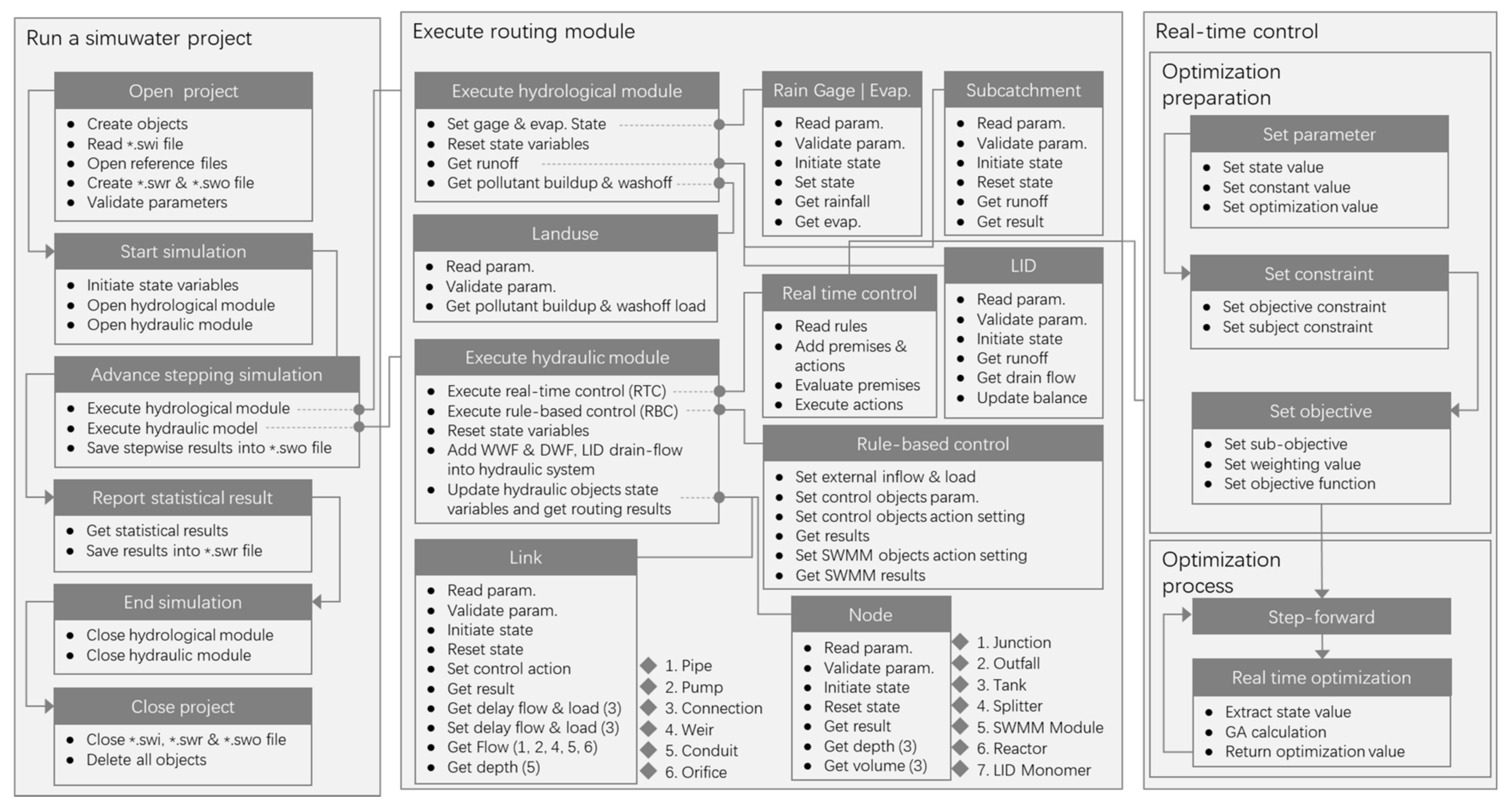
With experience in sewage treatment design and automatic control of infrastructure in the UDS, the North China Municipal Engineering Design & Research Institute Co., Ltd. (NCME) developed a new platform for UDS modeling—namely, the “Smart and Integrated Model of Urban Water (Simuwater, developed by NCME, Tianjin, China)”. The framework of Simuwater model is shown in Figure 1.
4.1. Coupling of Different Simulation Theories
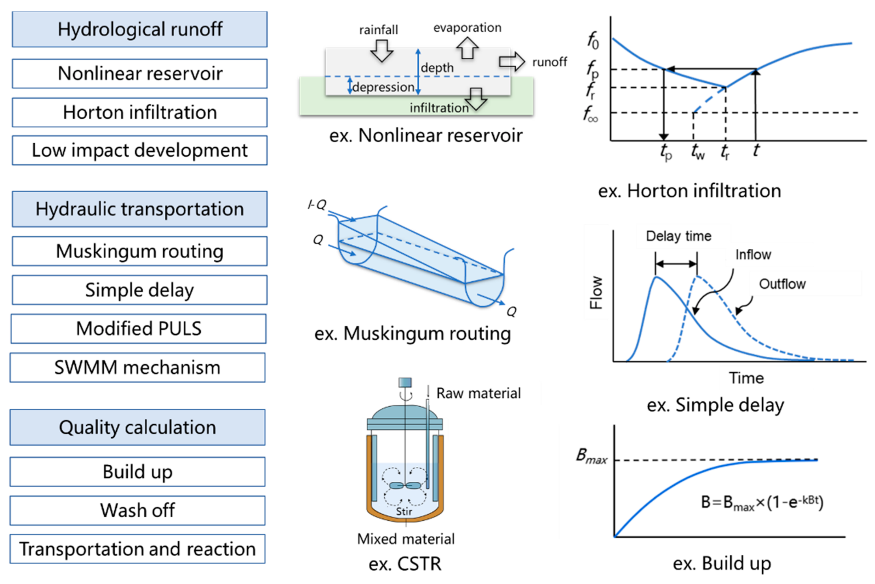
To achieve a balance between simulation speed and accuracy, integrated modeling software should contain an assortment of simulation methods for the modeling of various types of objects [25,34,35,38], as shown in Figure 2. Taking the conceptual models as the main part of the project, models with different simulation methods can be connected into a single project, without data interaction problems in the simulation process. The customer hopes to choose a suitable method for improving the modeling accuracy of the local area. For example, in a non-negligible area with various reverse slope pipelines, the SVE can be selected for this area, rather than the Manning equation [25] or the Muskingum method [34]. However, for other regions with insufficient basic data or large data ranges, it will be more appropriate to use the Muskingum method to generalize the simulation pipeline.
4.2. Integration of Multiple Objects
Ideally, integrated modeling software should have the following four primary modeling objects: source, network, plant, and river objects. Each object can have extensive sub-objects to simulate specific structures (Table 1).
In response to specific objects needing different simulation time-steps (depending on size and functions), an integrated modeling software allows for the application of a unified, complete, and dynamic time-step size in the simulation of different objects.
4.3. Optimization Control Applying
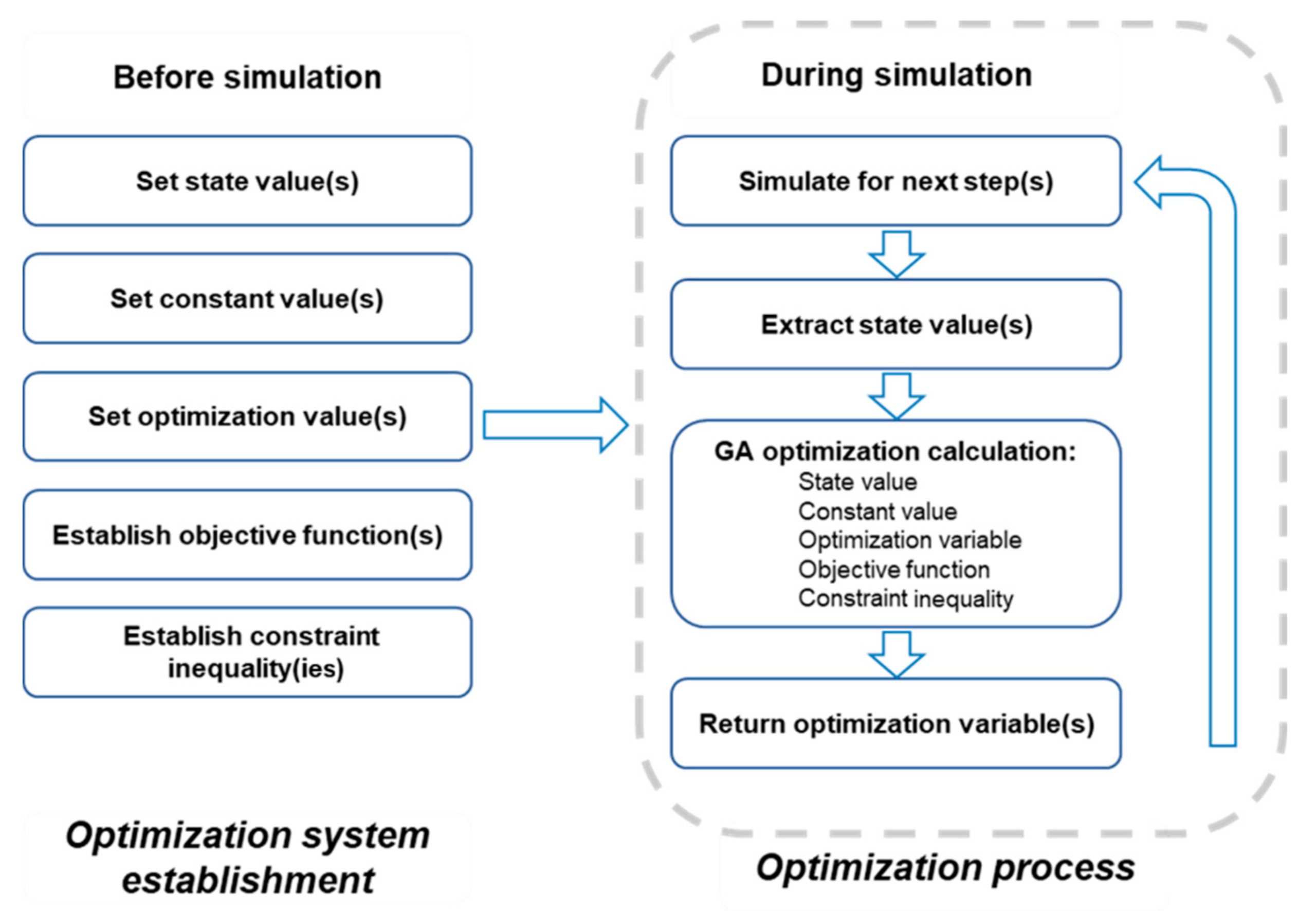
In integrated modeling software, optimization control should ideally be achieved by analyzing the current problems of the system, arranging the system facility state values and constraint conditions, formulating reasonable real-time control objectives, and establishing related functions, as well as building a complete and feasible optimization system [14,17,39]. This kind of method, based on model construction, is widely used in the aspect of CSO control [40], water quality protection [41], and flood reduction [12] and even in integrated environment targets control [10,42]. In the real-time operation/simulation process, data required for the optimization system must be extracted, the strategy formulation completed under real-time multi-control objectives, and the strategy returned to the operation/simulation system to complete the real-time optimization control within the control time-step, as shown in Figure 3.
Generally, a genetic algorithm (GA) is coupled in the integrated modeling software as the optimization algorithm and adjusts to suit the UDS optimization calculation [43,44]. With a client-specific objective function and constraint conditions, the optimization algorithm can determine the most suitable operation scheme. The calculation process usually takes less than 1 min, depending on the complexity of the optimization system, thereby meeting the time 5-min limitation of the RTC routing step.
Objective function usually contains several control objectives, and weight values are used to distinguish the importance of every objective.
where is the collection of controlled variable, is the ith optimization objective, is the weight value of the ith objective, and is the number of optimization objectives of the system.
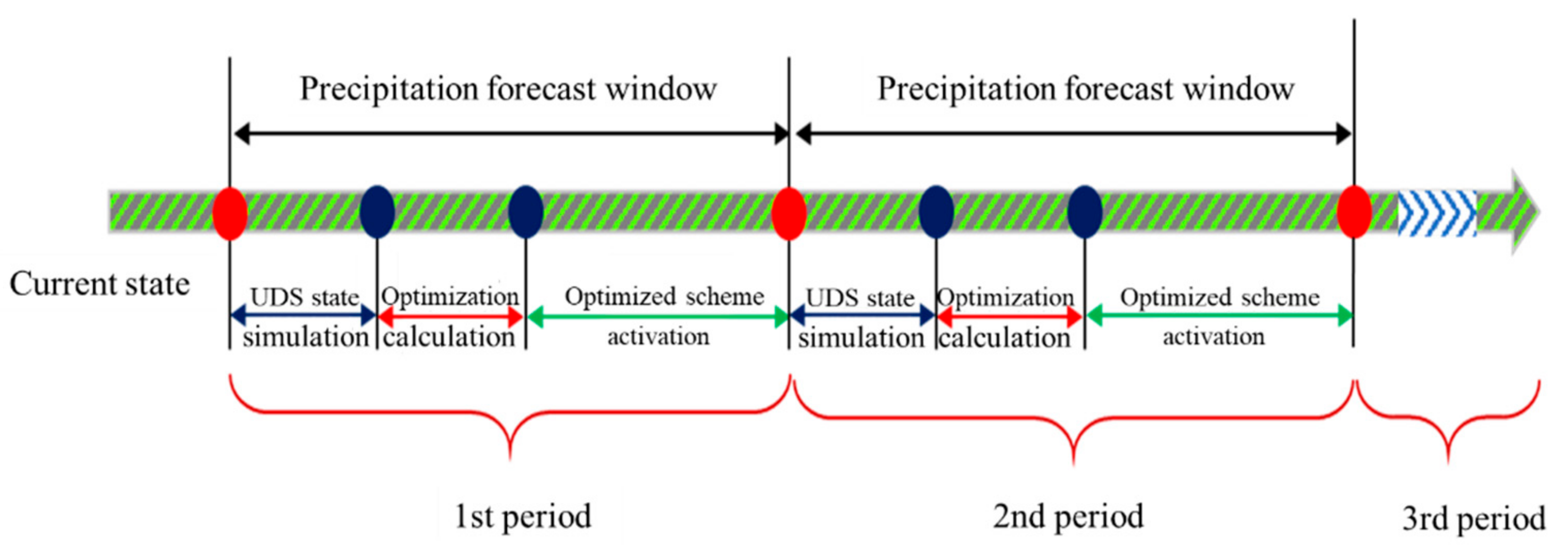
To achieve multi-period predictive control of the UDS, an integer multiple of the control step length (or simulation step length), such as N, can be selected as the predictive period, and the controlled variables and optimized variables can be expanded to N × n accordingly. According to the predicted state of the system in the future period, the algorithm is used to calculate N × n variable values simultaneously, but only the n variable values in the current step are executed—that is, under the premise of considering the system state in the future N time periods, we formulate an optimized operation plan for the current period, as shown in Figure 4. Although this method greatly increases the simulation and optimization calculation time, the formulated plan has a full-time (multi-period) optimality.
Within this context, we developed Simuwater, an integrated model for UDS, which is based on the rolling optimization method for calculating optimization operation rules according to rainfall prediction and system state simulation data, thereby actualizing the dynamic simulation of optimization control.
4.4. Development of Open-Interface
To meet specific demands, our integrated modeling software provides a large number of interfaces for secondary development (Table 2). Researchers and developers can use common programming languages, such as Python, C, and C++, to call the interfaces to expand the function. In addition, operators can set complicated operation rules in Python and can easily insert them into the software.
5. Case Study of RTC Simulation by Simuwater
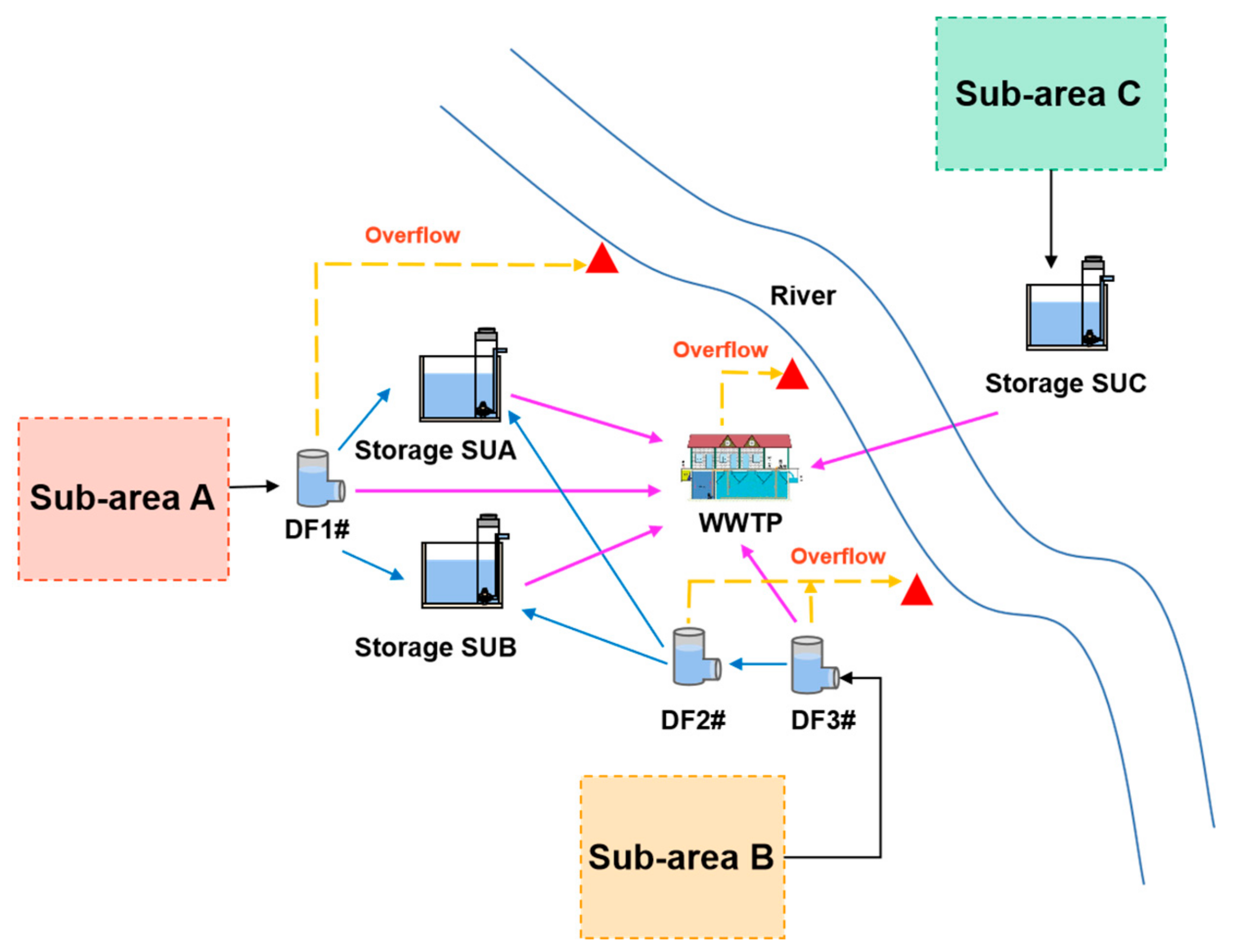
A Chinese city’s WWTP service area covers an area of approximately 900 ha. It is a combined drainage system, including one WWTP, three primary storage tanks (SUA, SUB, and SUC), and three key distributing wells (DF1#, DF2#, and DF3#) (Figure 5). To control the combined sewer overflow (CSO), storage tank SUA (capacity 15,000 m3), SUB (capacity 15,000 m3), and SUC (capacity 5500 m3) were established in subareas A, B, and C, respectively. Under the operating rules of the original design, the dry weather and combined sewage that do not exceed the discharge capacity of the drainage network in wet weather are directly transported to the WWTP. The combined sewage that exceeds the processing capacity of the pipe network or the WWTP in sub-areas A and B then enters storage tanks SUA and SUB, respectively, and is moved from the storage tank to the WWTP after the rainfall. The sewage from sub-area C enters storage tank SUC through the integrated pumping station and is then discharged into the WWTP.
According to the topological structure and basic data of the drainage system in this area, an integrated model of the system was built on the Simuwater platform.
5.1. Current Problems and Controlled Areas
During the selected rainfall period, the UDS had clear sewer overflow problems, specifically in distribution well DF2# and the WWTP (Figure 6). Owing to restrictions in the original design of the flow to SUA and SUB, the overload water could not be transported to the tanks in time. In addition, the emptying rules of the pumps in storage tanks were not appropriate and sent a “start” signal to the pumps immediately after the end of precipitation. However, owing to the long delay in sewage transport from sub-area C to the WWTP, the WWTP was not able to function at full capacity immediately after the rain stopped, with the emptying flow to the WWTP increasing the risk of CSO.
Considering this information, it became clear that the controlled area should cover the WWTP, storage tank SUA, SUB, and key distribution wells. The flow from storage tank SUC and other components was set as the boundary condition for the controlled area. Notably, the aim of systematic optimization control is to reduce the risk of CSO by making full use of the storage capacities of the storage tanks and optimizing the use of related pumps.
5.2. Reliability Analysis
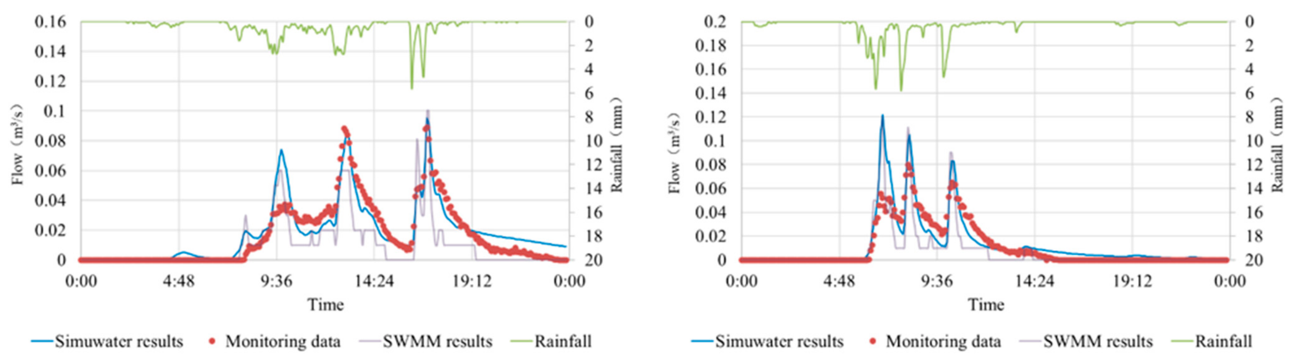
To ensure the reliability of the simulation results using Simuwater, monitoring and SWMM simulation data were used for comparison with the Simuwater results. Notably, the corresponding NSEs (to monitoring data: 0.84, 0.85; to SWMM data: 0.52, 0.73) were within the confidence interval, allowing the results to be verified, indicating the high reliability and stability of Simuwater simulation results, as shown in Figure 7. In addition, the SWMM model mentioned was calibrated. By comparing the monitoring data with the SWMM simulation results, the NSEs were calculated, and the sensitive parameters of the model were continuously adjusted until the NSEs meet the error requirements. The NSEs of the SWMM model were all above 0.6.
5.3. Controlled Variables, Constraints, and Objectives
A real-time value is the state value calculated during a simulation process. This type of value is essential for the optimization of the system. In our case, several real-time values of different components needed to be extracted. These values included the total inflow of distribution well DF2# and the total inflow of SUA, SUB, and the WWTP, as well as the volumes of SUA and SUB and the remaining treatment capacity of the WWTP. The controlled variables of the components included the outflow from DF2# to SUA and SUB and the emptying flows of SUA and SUB.
Constraint conditions describe the basic physical relationships that the entire system must satisfy and abide by in the optimal control calculation. Inequalities are typically used to transform constraint conditions into mathematical forms. In our case study, the constraint conditions were the maximum volumes of SUA and SUB and the maximum power of pumps in SUA and SUB.
In UDS models, the objective function is to transform the optimal objectives of the UDS (such as minimum CSO and stable storage tank volume) into a solvable mathematical function. In our case study, the objective function included the following three parts: minimum CSO in DF2# and the WWTP, target volume of SUA and SUB, and stable operation of pumps.
5.4. Optimization Results
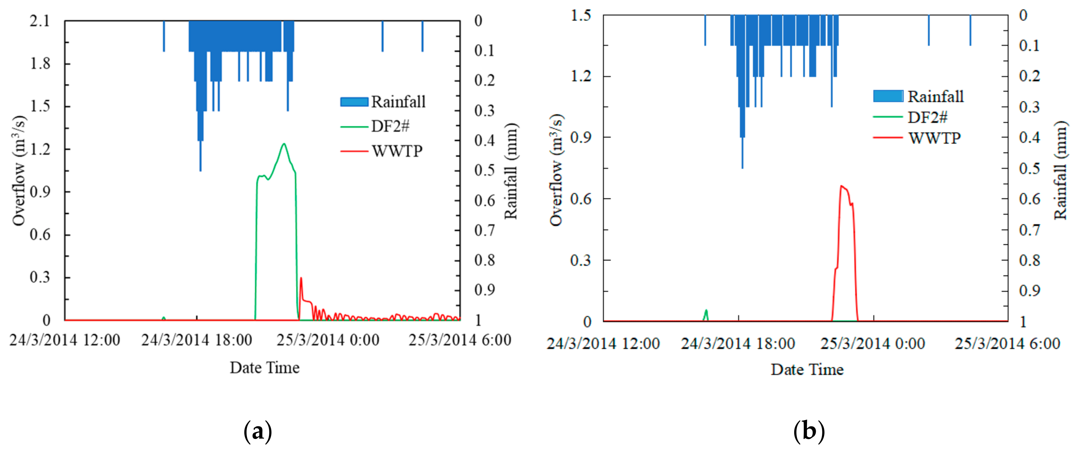
By comparing the simulation results of the original design and the optimal control, we demonstrated the effectiveness of Simuwater as an optimization strategy. Taking 9.4 mm rainfall as an example, the CSO of key facilities was reduced and managed by controlling the outflows of DF2#. Under the original operation rules, the CSO values of DF2# and WWTP were 7426 and 2397 m3, respectively. In contrast, the CSO under the optimization strategy was reduced to 0 and 1913 m3, respectively, with a reduction efficiency of 100% and 20.2%, respectively, as shown in Figure 8.
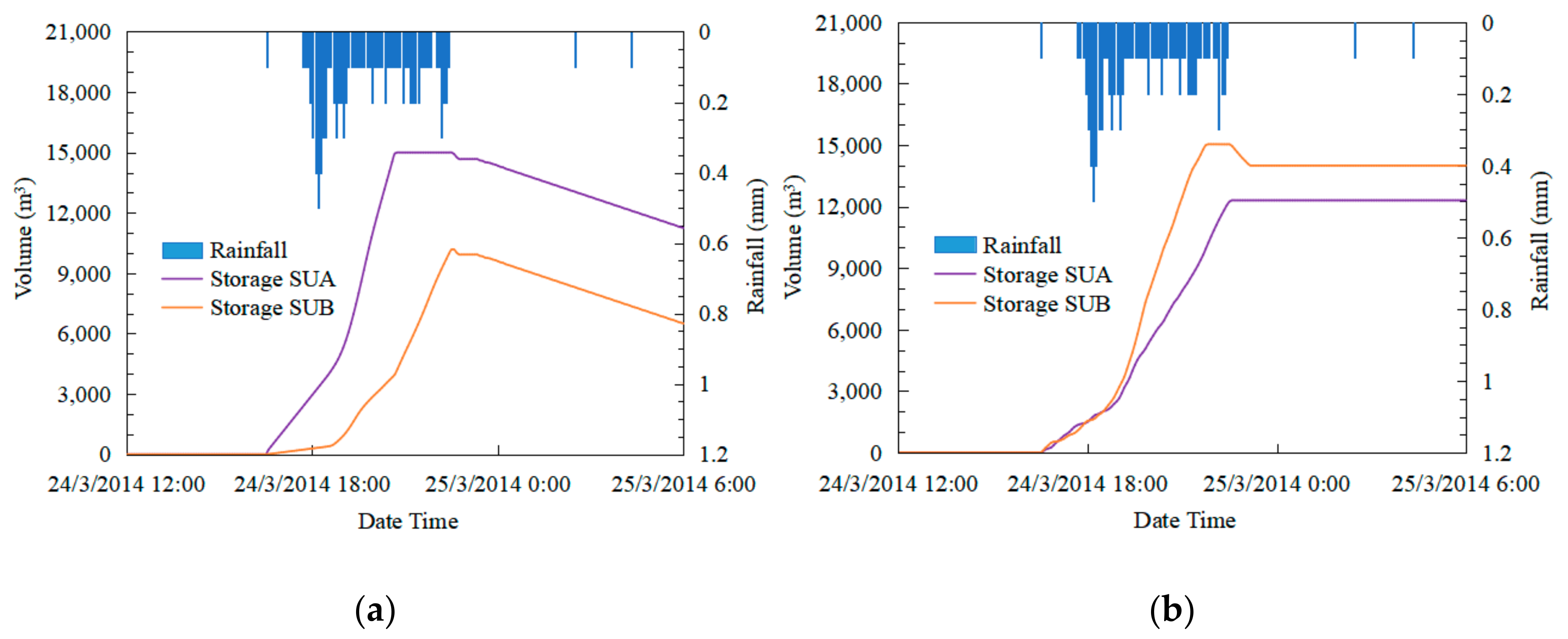
Simultaneously, in the multi-objective optimization system, by adjusting the weight of the balance volume target of the storage tanks, the volume of the storage tanks SUA and SUB could be maintained at approximately 14,000 m3, achieving the corresponding control effect (Figure 9).
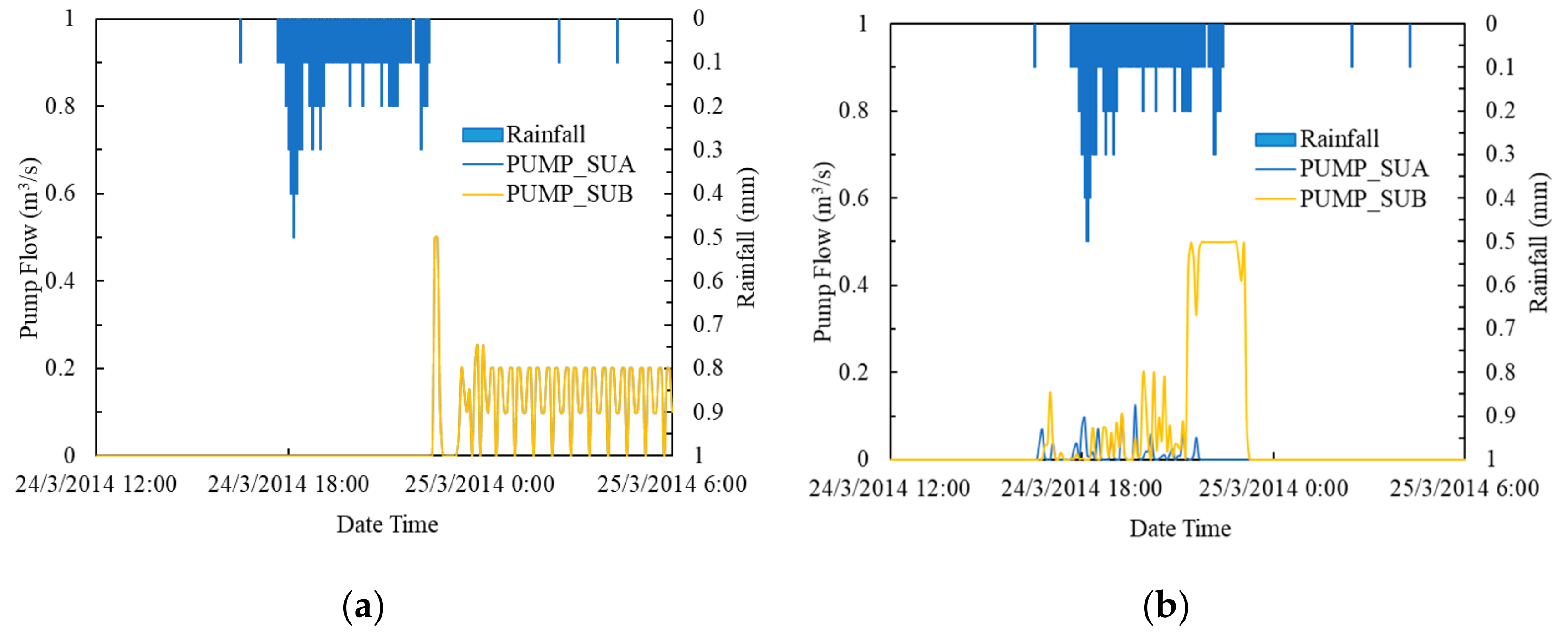
Under the original design, the regulation related to the emptying of storage tanks after rain was implemented (Figure 10). Specifically, after rainfall, the volume of the storage tanks decreased significantly, and the corresponding emptying pump started and stopped repeatedly according to the water-level control principle in the pump. Therefore, the goal of balancing the volume of the storage tank was not only to receive upstream water and reduce the overflow pressure of the upstream DF2# distribution well but also to prevent post-rain emptying from aggravating the load on the WWTP. Furthermore, because of the balanced volume of the storage tanks, the emptying of the pumps was more stable than in the original design, and the start and stop frequencies were significantly reduced, which was conducive to the sustainable operation of the equipment.
6. Conclusions
Within the context of technological development, solving the multiple problems of UDS in China (such as CSO and flooding), together with ensuring the safety of the UDS and improving the quality of the water environment requires the integrated operation of the UDS. This highlights the need for UDS models that include and allow for simulation, evaluation, and decision-making.
As a comprehensive model, Simuwater can simulate the water quantity and quality of all-element objects in the source, network, water treatment, and river modules. Furthermore, the model encompasses a high-precision linearization simulation method and combines the mechanism model with the conceptual model on the same platform to achieve a balance between timesaving and accuracy. Although we indicate the accuracy of the Simuwater model simulation through reliability analysis, future studies should focus on increasing monitoring data support. Notably, the rich control interface and optimization algorithm allows for multi-objective, full-time, and real-time control simulation of the UDS. The developed platform integrates simulation, analysis, optimization, and control, thereby breaking through the single function limitation of traditional models, and the platform encompasses the dual core functions of auxiliary design and optimization control. The application of this model can significantly improve the design, operation, and management of UDS.
To increase the depth and breadth of the Simuwater model, we suggest that future research also focus on simulating the internal process of the WWTP and pipeline deposition. In addition, further research avenues include the integration of machine learning and other related theories with more complete functions, such as sensitivity analyses. Furthermore, we suggest that it is necessary to conduct an in-depth study of the specific hydrology and hydraulic and water quality simulation mechanisms, as well as the coupling of further different methods and models to expand the application scenarios of Simuwater. With the continuous improvement in Simuwater functions and broad application practices, Simuwater can assist in the development of UDS models, from drainage simulation to the simulation of entire water systems.
Author Contributions
Conceptualization, H.W., L.Z. and J.L.; Data curation, Y.Q.; Formal analysis, G.H. and Y.Q.; Funding acquisition, H.W.; Investigation, H.W.; Methodology, H.W., G.H., L.Z. and J.L.; Project administration, H.W.; Resources, H.W.; Software, G.H., L.Z. and J.L.; Supervision, H.W.; Validation, H.W.; Visualization, G.H., Y.Q. and H.J.; Writing—original draft, G.H. and Y.Q.; Writing—review & editing, H.W. and H.J. All authors have read and agreed to the published version of the manuscript.
Funding
This research received no external funding.
Conflicts of Interest
The authors declare no conflict of interest.
References
- Zeng, Z.; Yuan, X.; Liang, J. Designing and implementing an SWMM-based web service framework to provide decision support for real-time urban stormwater management. Environ. Model. Softw. 2021, 135, 104887. [Google Scholar] [CrossRef]
- Sadler, J.M.; Goodall, J.L.; Behl, M. Leveraging open source software and parallel computing for Model. predictive control of urban drainage systems using EPA-SWMM5. Environ. Model. Softw. 2019, 120, 104484. [Google Scholar] [CrossRef]
- Gironás, J.; Roesner, L.; Rossman, L. A new applications manual for the Storm Water Management Model. (SWMM). Environ. Model. Softw. 2010, 25, 813–814. [Google Scholar] [CrossRef]
- Barnard, T.; Kuch, A.; Thompson, G. Evolution of an Integrated 1D/2D Modeling Package for Urban Drainage. J. Water Manag. Model. 2007, R227-18, 343–366. [Google Scholar] [CrossRef]
- Alam, M.J. Two-Dimensional Urban Flood Modelling for Real Time Flood Forecasting for Dhaka City; Asian Institute of Technology: Khlong Nueng, Thailand, 2002. [Google Scholar]
- Langeveld, J.G.; Benedetti, L.; de Klein, J.J.M. Impact-based integrated real-time control for improvement of the Dommel River water quality. Urban Water J. 2013, 10, 312–329. [Google Scholar] [CrossRef]
- Keupers, I.; Wolfs, V.; Kroll, S. Impact analysis of CSOs on the receiving river water quality using an integrated conceptual model. In Proceedings of the 10th International Urban Drainage Modelling Conference, Quebec, QC, Canada, 20–23 September 2015. [Google Scholar]
- Butler, D.; Schütze, M. Integrating simulation models with a view to optimal control of urban wastewater systems. Environ. Model. Softw. 2005, 20, 415–426. [Google Scholar] [CrossRef]
- Vanrolleghem, P.; Benedetti, L.; Meirlaen, J. Modelling and real-time control of the integrated urban wastewater system. Environ. Model. Softw. 2005, 20, 427–442. [Google Scholar] [CrossRef]
- Meng, F.; Fu, G.; Butler, D. Regulatory implications of integrated real-time control technology under environmental uncertainty. Environ. Sci. Technol. 2020, 54, 1314–1325. [Google Scholar] [CrossRef] [Green Version]
- Pleau, M.; Pelletier, G.; Colas, H. Global predictive real-time control of Quebec urban community’s westerly sewer network. Water Sci. Technol. 2001, 43, 123–130. [Google Scholar] [CrossRef] [PubMed]
- Sadler, J.M.; Goodall, J.L.; Behl, M. Exploring real-time control of stormwater systems for mitigating flood risk due to sea level rise. J. Hydrol. 2020, 583, 124571. [Google Scholar] [CrossRef]
- Shishegar, S.; Duchesne, S.; Pelletier, G. An integrated optimization and rule-based approach for predictive real time control of urban stormwater management systems. J. Hydrol. 2019, 577, 124000. [Google Scholar] [CrossRef]
- Fiorelli, D.; Schutz, G.; Klepiszewski, K. Optimised real time operation of a sewer network using a multi-goal objective function. Urban Water J. 2013, 10, 342–353. [Google Scholar] [CrossRef]
- Kändler, N.; Annus, I.; Vassiljev, A. Smart In-Line Storage Facilities in Urban Drainage Network. Proceedings 2018, 2, 631. [Google Scholar] [CrossRef] [Green Version]
- Schilling, W. A Survey on real time control of combined sewer systems in the United States and Canada. In Instrumentation and Control of water and wastewater treatment and transport systems, Proceedings of the 4th IAWPRC Workshop, 27 April–4 May 1985; Pergamon: Oxford, UK, 1985; pp. 595–600. [Google Scholar]
- Xin, D.; Huang, S.; Zeng, S. Design and evaluation of control strategies in urban drainage systems in Kunming city. Environ. Sci. Eng. 2017, 11, 1–8. [Google Scholar]
- Garcia, L.; Barreiro-Gomez, J.; Escobar, E. Modeling and real-time control of urban drainage systems: A review. Adv. Water Resour. 2015, 85, 120–132. [Google Scholar] [CrossRef] [Green Version]
- Bach, P.M.; Rauch, W.; Mikkelsen, P.S. A critical review of integrated urban water modelling—Urban drainage and beyond. Environ. Model. Softw. 2014, 54, 88–107. [Google Scholar] [CrossRef]
- Garcia, L.; Escobar, E.; Barreiro-Gomez, J. On the modeling and real-time control of urban drainage systems: A survey. In Proceedings of the 11th International Conference on Hydroinformatics, New York, NY, USA, 8 January 2014. [Google Scholar]
- Meert, P.; Nossent, J.; Vanderkimpen, P. Development of Conceptual Models for an Integrated Catchment Management: Subreport 1. Literature Review of Conceptual Modelstructures; Flanders Hydraulics Research: Antwerp, Belgium, 2014. [Google Scholar]
- Nasr, M.S.; Moustafa, M.A.E.; Seif, H.A.E. Modelling and simulation of German BIOGEST/EL-AGAMY wastewater treatment plants—Egypt using GPS-X simulator. Alex. Eng. J. 2011, 50, 351–357. [Google Scholar] [CrossRef]
- Saagi, R.; Flores-Alsina, X.; Kroll, S. A Model. library for simulation and benchmarking of integrated urban wastewater systems. Environ. Model. Softw. 2017, 93, 282–295. [Google Scholar] [CrossRef]
- Hauduc, H.; Rieger, L.; Oehmen, A. Critical Review of Activated Sludge Modeling: State of Process Knowledge, Modeling Concepts, and Limitations. BioTechnol. Bioeng. 2013, 110, 24–46. [Google Scholar] [CrossRef]
- Pleau, M.; Colas, H.; Lavallée, P. Global optimal real-time control of the Quebec urban drainage system. Environ. Model. Softw. 2005, 20, 401–413. [Google Scholar] [CrossRef]
- Lindenschmidt, K.-E.; Carr, M.K.; Sadeghian, A. CE-QUAL-W2 Model. of dam outflow elevation impact on temperature, dissolved oxygen and nutrients in a reservoir. Sci. Data 2019, 6, 312. [Google Scholar] [CrossRef]
- Moreno-Rodenas, A.M.; Tscheikner-Gratl, F.; Langeveld, J.G. Uncertainty analysis in a large-scale water quality integrated catchment modelling study. Water Res. 2019, 158, 46–60. [Google Scholar] [CrossRef]
- Ridolfi, L.; Porporato, A.; Revelli, R. Green’s Function of the Linearized de Saint-Venant Equations. J. Eng. Mech. 2006, 132, 125–132. [Google Scholar] [CrossRef]
- Litrico, X.; Georges, D. Robust continuous-time and discrete-time flow control of a dam-river system. (I) Modelling. Appl. Math. Model. 1999, 23, 809–827. [Google Scholar] [CrossRef] [Green Version]
- Sun, C.C.; Joseph-Duran, B.; Maruejouls, J. Efficient integrated Model predictive control of urban drainage systems using simplified conceptual quality models. In Proceedings of the 14th IWA/IAHR International Conference on Urban Drainage, Prague, Czech Republic, 10–15 September 2017; pp. 1848–1855. [Google Scholar]
- Ocampo-Martinez, C.; Bemporad, A.; Ingimundarson, A. On Hybrid Model Predictive Control of Sewer Networks. In Identification and Control; Spinger: London, UK, 2007; pp. 87–114. [Google Scholar]
- Achleitner, S.; Möderl, M.; Rauch, W. CITY DRAIN©—An open source approach for simulation of integrated urban drainage systems. Environ. Model. Softw. 2007, 22, 1184–1195. [Google Scholar] [CrossRef]
- Giraldo, J.M.; Leirens, S.; Díaz-Granados, M. Nonlinear optimization for improving the operation of sewer systems: The Bogota Case Study. In Proceedings of the 5th International Congress on Environmental Modelling and Software, Ottawa, ON, Canada, 5–8 July 2010. [Google Scholar]
- Bolea, Y.; Puig, V.; Grau, A. Discussion on Muskingum versus Integrator-Delay Models for Control Objectives. J. Appl. Math. 2014, 2014, 1–11. [Google Scholar] [CrossRef]
- Litrico, X.; Fromion, V. Analytical approximation of open-channel flow for controller design. Appl. Math. Model. 2004, 28, 677–695. [Google Scholar] [CrossRef]
- Murla, D.; Gutierrez, O.; Martinez, M. Coordinated management of combined sewer overflows by means of environmental decision support systems. Sci. Total Environ. 2016, 550, 256–264. [Google Scholar] [CrossRef] [PubMed]
- Zoppou, C. Review of Urban Storm Water Models. Environ. Model. Softw. 2001, 16, 195–231. [Google Scholar] [CrossRef]
- Van Daal, P.; Gruber, G.; Langeveld, J. Performance evaluation of real time control in urban wastewater systems in practice: Review and perspective. Environ. Model. Softw. 2017, 95, 90–101. [Google Scholar] [CrossRef] [Green Version]
- Lund, N.; Falk, A.K.; Borup, M. Model. predictive control of urban drainage systems: A review and perspective towards smart real-time water management. Environ. Sci. Technol. 2018, 48, 279–339. [Google Scholar] [CrossRef]
- Svensen, J.L.; Congcong, S.; Cembrano, G. Chance-constrained Stochastic MPC of Astlingen Urban Drainage Benchmark Network. Control. Eng. Pract. 2021, 115, 104900. [Google Scholar] [CrossRef]
- Sun, C.C.; Romero, L.B.; Joseph-Duran, B. Integrated pollution-based real-time control of sanitation systems. J. Environ. Manage 2020, 269, 110798. [Google Scholar] [CrossRef] [PubMed]
- Casal-Campos, A.; Fu, G.; Butler, D. An Integrated Environmental Assessment of Green and Gray Infrastructure Strategies for Robust Decision Making. Environ. Sci. Technol. 2015, 49, 8307–8314. [Google Scholar] [CrossRef] [Green Version]
- Shishegar, S.; Duchesne, S.; Pelletier, G. Optimization methods applied to stormwater management problems: A review. Urban Water J. 2018, 15, 276–286. [Google Scholar] [CrossRef]
- Afshar, M.H.; Afshar, A.; Marino, M.A. Hydrograph-based storm sewer design optimization by genetic algorithm. Rev. Can. De Génie Civ. 2011, 33, 319–325. [Google Scholar] [CrossRef]
Figure 1.
Framework diagram of the developed Smart and Integrated Model of Urban Water (Simuwater).

Figure 2.
The coupling of various mechanisms in the developed Smart and Integrated Model of Urban Water, Simuwater.
Figure 2.
The coupling of various mechanisms in the developed Smart and Integrated Model of Urban Water, Simuwater.

Figure 3.
The establishment process of optimization system before and during simulation.

Figure 4.
Optimization of the system before and during simulation.

Figure 5.
The distribution of primary wastewater facilities in a typical Chinese city, including storage units (SUA, SUB, SUC), distributing wells (DF1#, DF2#, DF3#), and the wastewater treatment plant (WWTP).
Figure 5.
The distribution of primary wastewater facilities in a typical Chinese city, including storage units (SUA, SUB, SUC), distributing wells (DF1#, DF2#, DF3#), and the wastewater treatment plant (WWTP).

Figure 6.
The controlled area of the UDS in a city of China on Simuwater platform.

Figure 7.
Comparison of results from the storm water management model (SWMM), the coupled Simuwater model, and a monitoring sensor (first NSE: Simuwater data to monitoring data; second NSE: Simuwater data to SWMM data).
Figure 7.
Comparison of results from the storm water management model (SWMM), the coupled Simuwater model, and a monitoring sensor (first NSE: Simuwater data to monitoring data; second NSE: Simuwater data to SWMM data).

Figure 8.
The combined sewer overflow of distribution tank (DF2#) and the wastewater treatment plant (WWTP) in (a) the original design and (b) optimal control with 9.4 mm rainfall on the developed Simuwater platform.
Figure 8.
The combined sewer overflow of distribution tank (DF2#) and the wastewater treatment plant (WWTP) in (a) the original design and (b) optimal control with 9.4 mm rainfall on the developed Simuwater platform.

Figure 9.
The volume of storage tanks SUA and SUB using (a) the original design and (b) optimal control with 9.4 mm rainfall on the developed Simuwater platform.
Figure 9.
The volume of storage tanks SUA and SUB using (a) the original design and (b) optimal control with 9.4 mm rainfall on the developed Simuwater platform.

Figure 10.
Pump flow of storage units (SUA and SUB) in (a) the original design and (b) optimal control under 9.4 mm rainfall on the developed Simuwater platform.
Figure 10.
Pump flow of storage units (SUA and SUB) in (a) the original design and (b) optimal control under 9.4 mm rainfall on the developed Simuwater platform.


Table 1.
List of simulation facilities of the developed Smart and Integrated Model of Urban Water (Simuwater).
Table 1.
List of simulation facilities of the developed Smart and Integrated Model of Urban Water (Simuwater).
| Objects | Sub-objects | Diagrams | Functions |
|---|---|---|---|
| Source | Catchment |  | Rainfall–runoff Dry weather flow (DWF) Inflow and Infiltration (II) Source runoff reduction Source pollution control |
| Green Roof |  | ||
| Bio-retention cell |  | ||
| Infiltration trench |  | ||
| Permeable pavement |  | ||
| Rain garden |  | ||
| Vegetative swale |  | ||
| Rain barrel |  | ||
| Network | Junction |  | Process collection, storage, and treatment of water process transmission and control of water |
| Outfall |  | ||
| Splitter |  | ||
| Tank |  | ||
| Pipe |  | ||
| Conduit |  | ||
| Connection |  | ||
| Pump |  | ||
| Weir |  | ||
| Orifice |  | ||
| Water treatment | Storage |  | Centralized or decentralized water storage and water quality control |
| Filter |  | ||
| Wetland |  | ||
| River | Reach |  | Terminal flow transmission Terminal pollution decay Water allocation and storage |
| Reservoir |  |
Table 2.
Interface name and description of the integrated urban drainage software, Simuwater.
| Interface Name | Description |
|---|---|
| Simuwater_run | Run the simulation process. |
| Simuwater_open | Open the simulation project. |
| Simuwater_start | Start the simulation process. |
| Simuwater_step | Advance one routing step of the simulation and update the elapsed time. |
| Simuwater_end | End the simulation process. |
| Simuwater_report | Report the simulation process. |
| Simuwater_close | Close the simulation process. |
| Simuwater_getMassBalErr | Obtain the continuity error of the simulation process. |
| Simuwater_setExtInflow | Set the external inflows of Simuwater node during the simulation process (if SWMM module is used). |
| Simuwater_setExtLoad | Set external inflow loads of Simuwater nodes during the simulation process. |
| Simuwater_setSplittedValue | Set the splitting values of splitters during the simulation process. |
| Simuwater_setPumpFlow | Set the pump flow values during the simulation process. |
| Simuwater_setReactorEmptyingValue | Set the reactor emptying values during the simulation process. |
| Simuwater_setWeirParams | Set the parameters of weir during the simulation process. |
| Simuwater_setSetting | Set action values of Simuwater objects during the simulation process (if SWMM module is used). |
| Simuwater_getResult | Return results according to object type, name, and variable type during the simulation process. |
| Simuwater_setSwmmExtInflow | Set the external inflows of SWMM node during the simulation process (if SWMM module is used). |
| Simuwater_setSwmmExtLoad | Set external inflow loads of SWMM nodes during the simulation process (if SWMM module is used). |
| Simuwater_setSwmmSetting | Set action values of SWMM control objects during the simulation process (if SWMM module is used). |
| Simuwater_getSwmmResult | Return SWMM results according to object type, name, and variable type during the simulation process (if SWMM module is used). |
| Simuwater_findObject | Obtain the object index according to the object type and object name. |
| Simuwater_isInEvent | Judge whether the current calculation time is within the rainfall event of the rain gauge. |
| Simuwater_init | Set folder path for the temporary swmm5ex.dll file. |
Publisher’s Note: MDPI stays neutral with regard to jurisdictional claims in published maps and institutional affiliations. |
© 2021 by the authors. Licensee MDPI, Basel, Switzerland. This article is an open access article distributed under the terms and conditions of the Creative Commons Attribution (CC BY) license (https://creativecommons.org/licenses/by/4.0/).
Share and Cite
MDPI and ACS Style
Wang, H.; Han, G.; Zhang, L.; Qiu, Y.; Li, J.; Jia, H. Integrated and Control-Oriented Simulation Tool for Optimizing Urban Drainage System Operation. Water 2022, 14, 25. https://doi.org/10.3390/w14010025
AMA Style
Wang H, Han G, Zhang L, Qiu Y, Li J, Jia H. Integrated and Control-Oriented Simulation Tool for Optimizing Urban Drainage System Operation. Water. 2022; 14(1):25. https://doi.org/10.3390/w14010025
Chicago/Turabian StyleWang, Haozheng, Guanyu Han, Lei Zhang, Yiting Qiu, Juntao Li, and Haifeng Jia. 2022. "Integrated and Control-Oriented Simulation Tool for Optimizing Urban Drainage System Operation" Water 14, no. 1: 25. https://doi.org/10.3390/w14010025
Note that from the first issue of 2016, this journal uses article numbers instead of page numbers. See further details here.