
Roman Water Transport: Pressure Lines

Faculty of ArtRadboud, Radboud University, 6525 XZ Nijmegen, The Netherlands
Water 2022, 14(1), 28; https://doi.org/10.3390/w14010028
Submission received: 13 October 2021
/
Revised: 3 December 2021
/
Accepted: 6 December 2021
/
Published: 23 December 2021
(This article belongs to the Special Issue Water Engineering in Ancient Societies)
Abstract
:In Roman times long distance water transport was realized by means of aqueducts. Water was conveyed in mortared open channels with a downward slope from spring to destination. Also wooden channels and clay pipelines were applied. The Aqua Appia, the oldest aqueduct of Rome, was constructed in the third Century BCE. During the Pax Romana (second Century CE), a time of little political turmoil, prosperity greatly increased, almost every town acquiring one or more aqueducts to meet the rising demand from the growth of population, the increasing number of public and private bath buildings, and the higher luxury level in general. Until today over 1600 aqueducts have been described, Gallia (France) alone counting more than 300. Whenever a valley was judged to be too wide or too deep to be crossed by a bridge, pressure lines known as ‘inverted siphons’ or simply ‘siphons’ were employed. These closed conduits transported water across a valley according the principle of communicating vessels. About 80 classical siphons are presently known with one out of twenty aqueducts being equipped with a siphon. After an introductory note about aqueducts in general, this report treats the ancient pressure conduit systems with the technical problems encountered in design and function, the techniques that the ancient engineers applied to cope with these problems, and the texts of the Roman author Vitruvius on the subject. Reviewers noted that the report is rather long, and it is. Yet to understand the difficulties that the engineers of those days encountered in view of the materials available for their siphons (stone, ceramics, lead), many a hydraulic aspect will be discussed. Aspects that for the modern hydraulic engineer may be common knowledge and of minor importance when constructing pressure lines, in view of modern construction materials. It was different in Vitruvius’s days.
1. Some Aspects of Roman Aqueducts
In Roman times aqueducts with mortared open channels, often roofed to limit evaporation loss and temperature rise, had a regular (but not necessarily uniform) downward slope from source to destination (Figure 1 and Figure 2) [1]. The longest aqueduct known is that of Constantinople, 250+ km. The Carthago and the Cologne aqueducts each were 95 km long, the Tempul aqueduct of Cadiz (Roman Gades, Spain) 83 km, while four of Rome’s eleven aqueducts surpassed 50 km (Table 1) [2].
The route of an aqueduct usually ran, for at least a part, through mountainous and uneven terrains. To guarantee that the water would flow from source to destination, bridges were constructed, tunnels were dug, and, at times, the channel was cut right out of the vertical rock face (Figure 3).
The terrain complexity frequently required great expertise in surveying techniques, planning and design [3]. The often-anonymous engineer, who had been given the task to bring good quality water to a town and to solve the problems that were encountered on the way, usually is lost to history together with the available engineering tools [4]. While bricks and natural stones were the main materials the mortared channels were constructed from, only few wooden-lined channels have been identified. Supported by a solid foundation and with thick walls the mortared channels were covered by a barrel vaulting, less often by flat slabs. Dimensions of the channel ranged widely (Table 2, Figure 4 and Figure 5).
For maintenance and repair channels were made accessible from the top by means of an opening, either round or square, spaced at regular intervals, at times combined with a vertical shaft in case of an underground course (manhole, inspection shaft, ‘regard’ as the French say, ‘Einstieg-Schacht’ for the Germans). Such vertical shafts were also dug when constructing tunnels, by connecting the shafts underground (Figure 6a,b).
The planning of an aqueduct route was an involved task. Vitruvius (First Century BCE) describes an instrument, called ‘chorobates’, a 20-foot-long narrow table with legs at square angles and vision-sights at either end (Figure 7), which he esteems the most accurate for leveling [5]. Plumb bobs would guarantee the horizontal orientation of the table, and in case of ‘windy weather’ water could be poured in a 5 foot long, 1 inch wide, and 1.5 inch deep hollow in the table top. When the water level is the same at both ends of the groove, the table top is oriented horizontal, and ‘one knows how large the slope (of the channel) is’, Vitruvius adds.
In the same section Vitruvius refers to Archimedes ‘who is known to state in his writings’ that ‘water surfaces coincide with a sphere concentric with the center of the sphere of the earth’. But that does not affect the leveling, Vitruvius adds, as long as the water level at both ends of the groove is at equal distance from the table top [6]. The consequence, however, is, that when one takes the horizontal level at location A, the sighting to location B will result—because of the curvature of the earth—in a position that is above the corresponding horizontal level at B (Figure 8). The greater the distance is, the worse this error becomes [7]. And for water to flow from A to B the channel should arrive below the corresponding horizontal level at B. For small distances the error is insignificant, increasing substantially for greater remoteness (Table 3). When surveying from a water source to the city, that is in downstream direction, repeated errors result to in failure for water to arrive where planned; when leveling upstream from city to source, the errors, if the source is reached, guarantee that water will arrive at destination.
Grewe 2014 is aware of the leveling problem and suggests that the course of an aqueduct should be leveled by having the chorobates repetitively installed by turning it around for 180 degrees and set it up at the end of its former position (Figure 9). Repeating the measurement will even out errors of the instrument itself as well as to allow for the curvature of the earth [8]. This method would theoretically do the job, but is quite if not entirely impractical in mountainous and wooded terrains, not to speak of the time consuming effort to repeatedly install the 6 m long chorobates. Some authors think that the chorobates is not at all suitable for leveling and suggest that the Roman engineers used the course of roads, rivers, and streams to plan their aqueduct [9].
Yet a solution for eliminating the error is to have a chorobates put up at both locations A and B (or set up an indication of its level at position A), then perform a back-sighting from B to A, and correct at location B for the error C that may be determined from the back-sighting. Then the slope may be set by lowering this new level at B for the required slope-level. Also the unfinished channel itself may serve as a large leveling instrument to determine the slope, as was common practice for instance in mid 20th century Turkey (Figure 10) [10].
In case low lying terrain had to be crossed, the channel was built on sequential arches so that the required slope could be maintained, the water arriving at the town at a height as planned. The aqueducts of Rome are known for the endless rows of arches in the Campania plains of which sections still stand (Figure 2), where at times channels were positioned on top of existing ones saving considerable costs and efforts. The 95 km Carthago aqueduct ran for 17 km on arches up to 30 m high to cross the Miliane plain (Figure 11) [11].
The slope (gradient) of the channel varied for each aqueduct and along its trajectory. Often the initial section was steep, while on approaching its destination the slope became less. The 50 km aqueduct of Nîmes with its famous Pont du Gard (Figure 12) started at present day Uzès with a gradient of 67 cm per kilometer from the spring that is situated only 17 m above the aqueduct’s end. After the 15 km stretch to the Pont du Gard it continued at only 7 cm/km for another 10 km, in extremely hilly terrain, incorporating another four bridges, a great achievement of precision even by today’s standards [12].
Not far downstream from one of its two springs the aqueduct of Aspendos (south coast of Turkey) had a slope of an estimated 160–170 m/km [13]. The Carthage aqueduct has a slope of 95 m/km for the first 6 km from the spring at Zaghouan. After French repairs in the 19th c. the Carthage aqueduct runs again today for a stretch of 70 km, providing Tunis with water and serving local populace on its way (Figure 13). The ruined Miliana bridge was substituted by a steel siphon. In 1995 its discharge was 150 L/s, almost 13,000 cubic meters/day.
To limit leakage, the inner walls of the channels were covered with ‘opus signinum’, a special type of mortar resistive to temperature changes and cracking [14]. Because the Romans often tapped karstic springs, over time calcareous incrustations (‘sinter’) accumulated on the walls and floor of the channels at a rate in the order of several mm’s per year. This could lead to a substantial reduction of channel dimensions and discharge. The 120 cm wide channel of the Nîmes aqueduct has deposits up to 50 cm wide on both inner walls, indicating continuous operation for many centuries (Figure 14). In later times large sinter blocks taken from the Nimes channel were used for construction purposes. In contrast Lyon’s Gier aqueduct shows no sinter at all as it was supplied from a non-karstic (granite) area.
The sinter of the Cologne aqueduct, having grown in thickness of just 1 mm/year, is of a high quality. In medieval times the up to 30 cm wide the incrustations in the channel were broken out to be reworked and polished, showing a travertine like structure from the seasonal deposits. It was regarded as a valuable material and served for altar slabs, ornaments, funerary ornaments, and pillars in churches in Cologne and surroundings. Known as ‘aqueduct marble’ the material was exported to Denmark, England, and Holland (Figure 15) [15]. Unworked sinter slabs from the Aspendos aqueduct were applied as grave stones in Selçuk cemeteries [16].
By analyzing isotopes of oxygen and carbon the deposits may serve as a high resolution paleo-environmental record [17]. Sinter imprints collected from the Barbegal mill complex in the south of France served to reconstruct the functioning of the 16 water wheels [18]. The 246 km fourth and fifth century CE aqueduct of Constantinople, longest of all Roman aqueducts and functioning for at least 700 years, is said to have been regularly cleaned of its massive calcareous deposits [19]. The eleven aqueducts of Rome had an estimated joint discharge of over one million cubic meters per day, a figure similar to the water provision of Paris in the 1970s. The 95 km aqueduct of Cologne conveyed 21.000 cubic meters per 24 h from the Eifel. The four aqueducts of Lyon delivered 75.000 cubic meters/24 hr [20].
2. Pressure Conduits: Inverted Siphons
The Roman engineer had only one force available to transport water over long distances: gravity. He had to make sure that the water could flow downstream from start to finish. Whenever a valley was too wide to be circumvented or too deep to be crossed by a bridge an ‘inverted siphon’ was constructed. With a siphon the water was made to flow to the other side of the valley by means of a closed conduit according to the principle of communicating vessels, a technique already applied in Hellenistic times (Figure 16 and Figure 17) [21,22]. Water from the aqueduct entered a ‘header tank’, from where it went into a pipe that ran down the slope of the valley, crossed the lowest part, then rose again on the other side. There the water ended in a ‘receiving tank’ at a level somewhat below the header tank. From the receiving tank the water continued its course to destination in an open channel again.
In the lowest part of the valley, the conduit was often installed on a ‘siphon bridge’ to have the river or stream there pass without damaging the line. The pressure in the conduit down in the valley could be considerable (Table 4) [23].
The highest pressure was reached in the 3150 m long Hellenistic Madradag-siphon at Pergamon, Turkey, 19 bar, corresponding to a max depth of 190 m (Figure 18). The siphon was fed by an over 40 km long ceramic unpressurized triple pipeline. Second with 15 bar is the Second Century BCE Kara-Bunar siphon of Smyrna of which virtual nothing has remained due to the enormous population increase of present day Izmir. In contrast the course of the Madradag siphon of Pergamon has not been disturbed and can be walked, in rather uneven and difficult terrain, where one passes bridges of later aqueducts and less deep Roman siphons [24]. From the header tank a free view of the acropolis exists (Figure 19). When leveling with a chorobates the error from the earth’s curvature amounts to 1.66 m, which is small compared with the level difference of 41 m between header tank and receiving tank. Viewing with a chorobates from the envisaged receiving tank on top of the acropolis towards the northern mountains, one may locate a spot on the slope almost 40 m down from the extant header tank. It was then to decide the construction location of the header tank above this point, but how the engineers knew how high one had to go up the hill from that point to have sufficient hydraulic gradient for their siphon remains open to question.
The longest pressure line is that of Cadiz on the south coast of Spain, Roman Gades, ending at the distribution tank in the town (Sifón de la Playa): 19.5 km (Figure 20) [25]. Conduit stones of the Sifón de la Playa have been recovered from the shore line and put up for inspection in a small Cadiz park (Figure 21). Not much remains of the header tank of the siphon de la Playa (Figure 22). Half way down from the Tempul spring, there is a second siphon (‘Sifón de los Arquillos’), to be discussed below.
The four aqueducts of Lyon (France) had a total of nine siphons (Figure 23). The Gier aqueduct, with 75 km the longest of Lyon’s aqueducts, had four siphons, up to 120 m deep and 3.5 km in length [26]. For the required capacity, nine to eleven 20 cm diameter conduits made of lead were laid out in parallel. The amount of lead for these siphons which all together had a length of 16.6 km, is estimated to have been 10,000 to 15,000 tons [27]. The lead has disappeared to be reused for roofs of churches, dwellings and other purposes. A number of header tanks and receiving tanks have survived as well as siphon bridges and parts of sloping ramps (Figure 24 and Figure 25). Some of the tanks have been partly restored.
The materials of the siphon-conduits were diverse: lead, stone, terracotta, or combinations of these have been used. They were assembled from prefab pipe elements having varying lengths: 40–70 cm for terracotta pipe elements, 50–100 cm for perforated stone blocks, up to 3 m for lead pipes. The pipe elements were joined by bringing the end of one pipe element into the somewhat larger end of the next (for terracotta conduits) or by means of socket and flange (for stone and terracotta conduits). The up to 1 m wide stones conduit elements of the siphons of Aspendos, Cadiz, Patara, Kibyra, and Laodikeia ad Lykum are of the latter type, as are the smaller 50 cm cubic conduit stones at Oinoanda (all in Turkey except Cadiz) (Figure 26 and Figure 27). Lead pipes were either cast, or—more often—made of leaden sheets that were bent around a wooden pole and soldered at the seam (Figure 28) [28]. Cast lead pipes could be joined with a stone element in between as found in Ephesos, or by means of a lead sleeve slid over both ends [29].
The pipes, depending on the quality of the water, were subject to calcareous incrustations—just as the open channels. Over the years the inner cross section would be reduced hampering the flow (Figure 29). The estimated 3000 conduit stones of the 1650 m long Aspendos siphon, destroyed by an earthquake in the 4th century CE, served as construction material for a new bridge over the nearby Eurymedon river. They were reused again centuries later by the Seljuks for a bridge they built on the ruins of the Roman predecessor. A number of conduit stones, with incrustation, can be seen in the fabric of the remains of the Roman bridge, as well as of its Seljuk counterpart that still stands today (Figure 30 and Figure 31) [30].
The Karabunar siphon of Smyrna is said to have been made of stone elements alternated with terracotta pipes [31]. The joints of stone and ceramic conduits were sealed with a mixture of live chalk, oil, and herbs, which expands when moisturized [32].
Sections of lead siphon-conduits have been preserved. A 90 cm long fragment with diameter 31–34 cm, is all that remained from a find of about 10 tons of lead conduit that was retrieved in 1980 from the Rhône river near Vienne at extremely low water level (Figure 32 and Figure 33). Regretfully the pipes have been melted down without prior investigation, only the 90 cm fragment remaining. The find shows that at Vienne the Rhône river was crossed with a siphon on the river bed. The pipe section that was put ‘dans la four’, in the oven, to be melted down is estimated to have been an astonishing 80 m long [33].
Near Arles, France, 33 lead pipes were recovered from the Rhône river over the years 1570–1825. Now in the Arles museum they have been investigated by J. Hansen of Denmark (Figure 34) [34]. The pipes, with a length of 3 m and an inner diameter of 10–12 cm have a lead seam along their length and were part of a siphon that also crossed the Rhône, between Arles and Trinquetaille. The pipe elements were fixed to each other by inserting one end into the larger end of the next pipe, and driving a large nail through both ends. Subsequently the joint was sealed with a thick layer of soldered lead that also covered the nail that must have hampered the flow to some extent (Figure 35).
Hansen noted that the joints were no weak points in the line (‘waren nicht das schwache Glied der Kette’), an indication of the superior soldering techniques of the Romans. Such conduits may be regarded as being made of a homogenous material. This is not the case for conduits with joints sealed with the expanding mix. Although this material is highly resistive to pressure (a high compressive strength), its tensile strength is much lower than that of stone, lead, or terracotta, the material the pipe elements are made of. These conduits are susceptible to bursting at the joints.
3. Siphon Conduits and Water Pressure
Ancient pressure conduits may thus be split into two categories. Cat.I conduits are made of lead, with soldered joints. These conduits can be regarded as ‘homogenous’, with a uniform material all along the conduit, that is, the tensile strength parallel to the conduit axis is equal to the tensile strength perpendicular to the conduit axis. Cat.II conduits have joints sealed with the weak expanding mix (resistive to pressure but having a low tensile strength, its breaks easily). Here, the tensile strength parallel to the conduit axis (at the joints) is lower than the tensile strength perpendicular to the conduit axis (of the stone material). These conduits must be considered as ‘non-homogenous’.
Theoretically, a pipe can burst in two ways when the inside pressure becomes too high: along its length, or perpendicular to its length. The minimum pressure to burst along its length P(l) equals (Figure 36):
where t(p) = tensile strength of the material of the pipe wall perpendicular to the pipe axis (force/m2);
P(l) = t(p) · (d/2R)
d = pipe wall thickness;
R = inner radius of the pipe.
To have the pipe burst perpendicular to its axis, the pressure must at least be P(p), where
P(p) = 2 · t(l) · (d/R) · (1 + d/R) with t(l) = tensile strength along pipe axis (Figure 37).
For pipes made of homogenous material (Category I conduits) the tensile strength is equal in all directions: t(p) = t(l). From this follows P(p) > 2 · P(l). Homogenous conduits will always burst along their length when the inside pressure gets too high. For Category II conduits, with t(p) > t(l), this may not be the case as the low tensile strength along the conduit axis (the low tensile strength of the sealing mix) make the Cat.II pipes are prone to burst at the joints. Thus, the choice of the material for the pressure pipes requires that precautions must be taken to guarantee proper functioning of the siphon and to prevent damage. Factors influencing failure are static pressure, forces generated by the water flow, effects from presence of air in the conduit, and the possibility of the occurrence of pressure surges, which are described below.
4. Static Pressure
If a siphon is just filled with water—not flowing—only static pressure has to be reckoned with. The static pressure p at any point in the conduit is related to the vertical distance h between that point and the free surface of the water:
where
ρ = specific mass of water = 1000 kg/m3;
g = gravitational acceleration = 9.81 m/s2;
h = vertical distance below free surface of the water in m [35].
For a conduit full of water, the water pressure p exerts forces perpendicular to the pipe wall along its circumference, which are evened out as long as the tensile strength of the pipe material is sufficiently high. This is true for both categories of conduits provided that, for Cat.II conduits, the combined wall thickness of the male–female joints has a similar tensile strength as the pipe wall itself (and that displacement of a pipe element along the conduit axis is prevented by the next pipe element (Figure 38)).
If indeed properly secured, Cat.II conduits are, in turn, susceptible to splitting along the length of the line, as an element from the Delik Kemer siphon of the Patara stone aqueduct shows (Figure 39; for this siphon on the south coast of Turkey, see below).
5. Bends in the Line
Things change, however, where there is a bend in the line. On the pipe element at the bend, the static pressure exerts a net outward force along the bisector of the bend angle, with magnitude F, in newtons (Figure 40):
where
p = static pressure (newton/m2);
A = cross-section of conduit (m2);
α = angle of bend.
For an angle of 180 degrees, a ‘U-turn’, this force is at its maximum (sin(α/2) = 1), while for a straight conduit, with α = 0, this force is of course zero. For a bend of 30 degrees in a 28 cm-diameter conduit at a pressure of 40 m of water column, as in the case of the Aspendos siphon (for the Aspendos siphon, see also below), where the conduit turns from going down from the header tank to horizontal, this force F (in newtons) becomes considerable:
This is a force equivalent to a weight of 1275 kg (or 1275 kg-force (kgf)). For vertical bends changing from going down to horizontal or from horizontal to going up, such force may be readily countered by an adequate foundation of the conduit. For the 3250 m-long and 190 m-deep Madradag siphon at Pergamon, the forces were significant due to the high pressure (see Figure 18). The conduit consisted of pipe elements of cast lead, 2–3 m long, that were joined by means of lead sleeves slid over neighboring pipe ends. The 17.5 cm-inner diameter conduit was kept in place by having every individual pipe element fitted into a perforated trachite stone slab and burying the entire conduit (Figure 41 and Figure 42).
At the two vertical 20-degree bends on top of two intervening hills, the Caputlu Tepe and the Kaleardi Tepe, 136 and 146 m below the header tank, the conduit changes from rising up to going down, meaning the force from static pressure is directed upward. Here, the fixation stones (anchor stones) are larger (respectively, 1.5 cubic meters and 3.4 cubic meters) to compensate for the upward force of about 11,000 and 12,000 newtons (over 1000 kgf) at these points [36]. The estimated weight of the anchor stones of 8500 kg and 3750 kg (Caputlu and Kaleardi) was sufficient, if not overdone, to compensate for the uplifting force from static pressure (Figure 43 and Figure 44).
For pressure lines of Category II, the force from static pressure exerted on a pipe element that makes up a bend will be diverted to the neighboring pipe elements, but only as far as the sealing material keeps the pipe elements together. The tensile strength of the sealing material is comparatively weak, so that additional means were needed to prevent the pipe element(s) of the bend being pushed out of position. For vertical bends this could be achieved by having the conduit laid on a solid foundation (where a descending conduit changes to horizontal or v.v.) or by adding mass enlarging the weight, as was done at Pergamon on the top of the intervening hills. The Roman author Vitruvius indeed recommends for such pipelines to make the vertical bends of special red stone (‘ex saxo rubro’), undoubtedly known for its strength [37]. However, for horizontal bends, even if minor, additional measures must be taken, such as increasing friction forces with the underground by sand ballast, by building a wall pushing back, or by fastening the conduit elements to each other with bands, as Vitruvius advises [38]. The last measure was carried out for the Delik Kemer siphon of the Patara aqueduct, which will be discussed here shortly.
6. The Delik Kemer Siphon of the Patara Aqueduct
The 500 m and 20 m-deep ’Delik Kemer’ stone siphon of the Patara aqueduct on the south coast of Turkey was built on a 10 m-high and narrow cyclopean wall crossing a 30 m-deep depression. Over 90 m of the stone conduit is in situ on top of the wall today (Figure 45).
Although the wall has no bends, the in situ conduit on the narrow wall appears rather sinuous (Figure 46). In order to prevent sideways dislocation, the 80–105 cm-wide male–female jointed conduit elements were, at some time, fixed to one another by metal clamps, as is attested by fixation holes on the side and on top of the in situ conduit blocks (Figure 47a,b).
Two almost identical inscriptions, on either side of the Cyclopean wall above each of the two passages, recount of the destruction of the siphon by an earthquake in 68 CE, during the reign of Nero [39]. Patara city remained devoid of water for almost three years before the siphon was restored again (Figure 48 and Figure 49).
The inscription also recounts of the construction of a second siphon, consisting of three parallel ceramic pipelines that were installed after the earthquake as a safety measure.
Some intact 29 cm-outer diameter and 41 cm-long ceramic pipes with a wall thickness of 9.25 cm and a bore of 10.5 cm that presumably belonged to this ‘security siphon’ have been found in the early 1990s (Figure 50) [40]. The intact pipes are now lost, but fragments lie astray in the surrounding area.
Remarkably, an upstream section of the cyclopean wall, supporting the start of the in situ conduit elements, incorporates a large number of such fragments. Here, the wall was apparently restored using fragments of the triple ceramic siphon as construction material (Figure 51 and Figure 52).
This may indicate that the siphon and part of the cyclopean wall was destroyed again, possibly by the 365 CE earthquake of Crete, and subsequently restored once more [41]. Conduit stones fallen of the wall were reinstalled but not all in the original order, the fixation holes no longer all corresponding, while a number of newly made conduit stones, some made from ‘spolia’ (reused construction material), replaced destructed ones. This may account for the rather sinuous course of the present line (and therefore susceptible to dislocation from water pressure and pressure surges) of which 182 elements over a length of over 90 m are on top of the wall today, a section that includes the siphon’s lowest point.
The metal clamps were removed or stolen when the siphon was again in ruins, so supporting walls had to be constructed on either side of the line on the narrow top, some remains in situ today, to prevent sideway dislocation of the conduit stones from pressure and pressure surges (Figure 53 and Figure 54) [42].
Once in operation the siphon was of course susceptible to static pressure and pressure surges that could lead to the occurrence of conduit stones to crack, as indeed happened (Figure 39). Then the line had to be repaired, for which a exceptional technique was developed to insert new conduit stones without dismantling the line. The trick was to remove the damaged element plus the two neighboring conduit stones, and put two specially shaped elements back on either side of the opening. Then a third fitting element was slid from above into the remaining gap to have the line restored again. Such repaired spot is seen in the in situ conduit, while the special shaped stones (one broken in half) may be noted on the terrain close the Cyclopean wall (Figure 55, Figure 56, Figure 57 and Figure 58).
A number of conduit stones show vertical holes from the top to the bore. The holes could be closed by mortared stone plugs and additionally secured with metal clamps, to prevent the plugs to blow out when operating the siphon (Figure 59). Similar holes have been observed for the siphons at Aspendos, Laodikeia ad Lykum (some stone plugs in situ), Roman Ankara (Ankara museum garden, with one stone plug in situ), Smyrna (Turkey), Hippos-Susita (Israel). The holes were probably made in relation to cleaning procedures and removing obstructions [43]. At the lowest point of the Patara siphon three holes in the side enabled emptying of the conduit (Figure 60) [44].
7. Effects from the Flow of Water
Forces exerted onto the conduit from the flow of water are generated by the friction between the water and pipe wall (‘drag’), and, at bends, by the force that is needed to change the direction of flow (‘inertial thrust’). Because the velocity of the water at the inner surface of the pipe wall is zero, the drag is mainly determined by viscosity of the water and roughness of the wall. Assuming that wall roughness and conduit diameter are similar all along the conduit, each pipe element will undergo a force in the direction of flow. To stay fixed the pipe elements must exert an equal force in opposite direction. This drag-force has a certain value per unit length of conduit. In an operating siphon the velocity of the water will have a fixed value, mainly determined by the head of the siphon, conduit diameter, roughness of the inner conduit surface. Because the water velocity is the same all along the line there is no increase in kinetic energy, so that the energy won by gravity between header tank and receiving tank must be equal the energy lost by drag along the conduit plus energy lost by turbulence [45]. Discarding the energy lost by turbulence, the energy won by gravity represents an upper limit of the energy lost by drag (Figure 61).
For the stone siphon of Aspendos, with a length of 1670 m, the header tank being 14.5 m above the receiving tank, this force is about 5.24 N per meter of conduit (diameter 28 cm). For the average length of a pipe element of 50 cm this represents a force of 2.62 N which is the equivalent of a weight of 270 g. This small force will be readily yielded by the friction forces between the heavy conduit stones and the underground.
At bends in the conduit the direction of flow changes whereby a force is exerted onto the conduit element that makes up the bend (‘inertial thrust’). This force is related to the change of direction of the impulse of the water (impulse = mass times velocity) and tends to push the conduit element out of position. To be precise, this is the force that has to be exerted by the conduit element onto the flowing water to the effect that the direction of flow changes. It may be represented by a vector along the bisector of the angle of the bend, taking that the magnitude of the velocity of the water does not change (Figure 62).
From Figure 62, it may be seen that the change in impulse dP of a volume of water A·dx (A is the cross-section of the conduit, and dx is the thickness of a corresponding slice of water) that goes around the bend equals
where
ρ = specific mass of water (kg/m3);
ρ · A · dx = the mass of the slice of water going around the bend;
v = mean flow velocity of the water (m/s);
β = angle of the bend.
The mean flow velocity v of the water in the conduit may be estimated with the formula of Darcy–Weisbach [46]:
where
g = gravitational acceleration = 9.81 m/s2;
ΔH = difference in level between start and end of the conduit, the ’head’ (m);
Rh = hydraulic radius of the conduit = D/4 for full flow;
D = inner diameter of the conduit (m);
λ = friction factor related to the roughness of the inner wall of the conduit (dimensionless, related to the irregularities of the inner surface of the pipe, to be determined from handbooks);
L = total length of the conduit (m);
C = () which has a fixed value for a specific conduit.
The formula simply means that the longer a conduit is, the lower the velocity of the water will be, while the larger the difference in level between start and end of the conduit the faster the water will flow. The flow velocity in ancient siphons was not very high. For the 1.670 m long Aspendos siphon with its 28 cm diameter stone conduit, a wall roughness of at least some mm’s (stone conduit, λ ≈ 0.043) and a ΔH of 14.5 m, as well as for the 3.250 m long Madradag pressure line at Pergamon, with wall roughness less than 1 mm (lead conduit, λ ≈ 0.026) and a ΔH of 41 m, the flow velocity for maximum discharge is about 1 m/sec (which is average walking speed).
This means that for a horizontal bend of 55 degrees, which is the case at Aspendos (see below for the course of the Aspendos siphon) the required force F is 57 Newtons, equivalent to a weight of about 6 kg [47]. The magnitude of this force is small compared to the forces from static pressure (as discussed above for a 30 degrees bend in the Aspendos line: 12,507 Newtons; for a bend of 55 degrees the force from static pressure would be even 22,262 Newtons, the 57 Newton being virtually nil in comparison). The friction forces between the heavy conduit stones and the foundation on which they are positioned may be assumed much larger than the force from inertial thrust. The consequence is that for ancient siphons the effects of flow can be neglected, and no measures were needed preventing the line to break apart at the bends from forces of flow. This may of course not be the case for high flow velocities that occur in modern systems.
Several authors [48] discuss oscillations of the water column occurring during rapid start-up (‘sloshing’) that may contribute to initial flow instabilities. The Aspendos siphon has two ‘hydraulic’ towers with open basins on top by which the siphon was split up into three consecutive siphons. One possible reason for the hydraulic towers would be the elimination of any entrained air pockets as well as helping to damp initial start-up flow instabilities. To possibly limit initial flow instabilities a procedure involving a very slow water filling rate was prescribed by Vitruvius in the first Century BCE. See below for the Aspendos siphon and its hydraulic towers [49].
8. The Presence of Air in the Line
There are several reasons why air in the conduit may interfere with the operation of a siphon. At the start-up of a siphon air may accumulate in air pockets at the downstream side of high points (Figure 63). These air pockets, depending on how far below the header tank they occur, reduce the pressure difference between header tank and the end of the siphon, the receiving tank. The siphon then delivers less water than envisaged, and it may even be so that the siphon does not start at all and the header tank just overflows. In deep siphons this effect is reduced as air pockets will be compressed, while some of the air may be absorbed into the water [50].
As seen above the Madradag siphon of Pergamon has two high points corresponding with the two intervening hills, the Çapultu Tepe end the Kaleardi Tepe. Because of the high static pressure at these points, some 140 m below the header tank and 100 m below the receiving tank, the air pockets were compressed to the extent that the discharge of the siphon was reduced to only 90% of its maximum value (Figure 64) [51].
One may ask whether the engineers were aware of it: the siphon functioned as expected. But it is a problem that plays a role even today [52]. For a modern 60 km long and 2 m-diameter waste water conduit in the Netherlands functioning at a 30% capacity loss, it appeared, after 10 years of investigation, that air entrainment at the inlet was the cause of air pockets forming at local high points that reduced the debit [53].
However, there is an additional problem that has to be reckoned with. Once filled and functioning, air may be entrained into the conduit at the header tank and transported to the air pockets, enlarging their volume. The result is a further reduction of the head driving the siphon, which in the end may even lead to a total stop. The intake at the header tank of the Madradag siphon was positioned not far below the upper edge of the tank, some 10–15 cm. The tank is in derelict state today, but a 1906 photo by Gräber shows more details (Figure 65 and Figure 66). The 1.57 m deep Hellenistic tank was originally divided in two parts by a separating wall C, a settling section B supplied by a triple clay conduit A, and a tank for the supply of the Madradag pressure line. Originally there were three openings in wall C to sufficiently supply this second section and with it the Madradag pressure line starting at E. The tank was adapted by the Romans to supply the lower city of Pergamon, adding an extra 3 holes in wall C (5 are visible in Gräber’s photograph), and a wall D in order to separate the supply to the Pergamon acropolis by the Madradag line from their new waterway to the lower city (with two Roman ceramic pipe lines starting at F) [54].
The upper side of the 18 cm-wide conduit of the Madradag siphon was located just 14–15 cm below the water level in the tank, as set by an overflow ridge. Entrainment of air into the line could not be avoided here. Moreover, entrainment of air in the header tank into the siphon conduit was common practice because the intake in the wall of the header tank was, as a rule, positioned at or not far below the water level in the tank [55]. When entering the conduit, the water may form a vortex, pulling air bubbles into the conduit (compare the emptying of a bathtub) (Figure 67 and Figure 68). The deeper the intake is below the free water surface, the less readily vortices will form.
The upper side of the 18 cm wide conduit of the Madradag siphon was located just 14–15 cm below the water level in the tank as set by an overflow ridge. Entrainment of air into the line could not be avoided here. Moreover, entrainment of air in the header tank into siphon conduits was common practice, because the intake in the wall of the header tank was as a rule positioned at or not far below the water level in the tank [55]. When entering the conduit the water may form a vortex pulling air bubbles into the conduit (compare the emptying of a bathtub) (Figure 67 and Figure 68). The deeper the intake is below the free water surface, the less readily vortices will form.
There is a minimum submergence required to avoid vortex formation with entrainment of air (the so-called ‘submergence law’) [56]:
where
S = minimum submergence to avoid vortexing (m);
D = diameter of inlet pipe (m);
v = velocity of water in conduit;
c = a constant.
For the Madradag siphon, and also for the siphons of Lyon (see below) and Aspendos for instance the submergence was much less than required (Figure 69). Once the siphons were running, air thus entered the conduit together with the water and moved down with the flow.
There is archaeological proof that air was indeed entrained in siphons. A conduit stone of the in situ remains of the twin siphon at Laodikeia ad Lykum (Turkey) shows substantial incrustations. The sinter (calcareous incrustation) is thickest on the sides but less thick at the top (see Figure 70). That is because at the top side entrained air has prevented sinter deposits to a considerable extent. At the bottom there is a groove, where sinter building was reduced because of debris rolling with the water [57].
At Aspendos a few con¬duit stones are still lying along the siphon’s course. In 1890 Lanckoronski noted about one of them: ‘Einen der Wasserleitungsquadern … ¾ von Sinter gefüllt … die gebliebene Öffnung gleich einem Dreieck mit gerundeten Ecken und eingezogenen Seiten’ [58], (‘One of the conduit stones … for ¾ filled with calcareous incrustation … the remaining bore like a triangle with rounded edges and caved-in sides’). A conduit stone with this remarkable sinter was indeed found in the 1990’s (Figure 71). One side of the triangular sinter shows accumulation of debris that was caused by some malfunctioning at the header tank, subsequently covered again with a thin layer of sinter. Obvi¬ously that must have been the bottom side of the conduit element. Thus the top side of the triangle was at the upper side, and again, entrained air, always at the top of the conduit, had prevented deposition of sinter to some degree.
For the Madradag siphon air will be entrained at the header tank and transported to the air pockets at the high points formed when filling the siphon, enlarging their volume. Yet, at the downstream side of the air pockets there is a transition of a partly filled conduit (the water passes underneath the air pocket) to full conduit flow. At this point, of considerable turbulence, air may again be entrained further down the conduit with the water flow, reducing on its turn the volume of the air pockets. Whichever process is more important determines what will happen [59]. The conduit of the Madradag siphon at the header tank had a slope angle much larger than downstream of the high points, 18 degrees vs 6 and 8 degrees [60]. Therefore air was less readily transported down the conduit at the header tank but rather more easily at the downstream side of the air pockets at the hill tops. This means that after start-up the air pockets became depleted and the siphon developed to full capacity on its own. Whether the designers were aware of this phenomenon is questionable, but the siphon operated as expected and brought water to the acropolis on top of the hill, no doubt to the amazement and wonder of her people.
A quite different situation existed for one of the siphons of the Yzeron aqueduct of Lyon (Figure 23). The Grezieux-Craponne-Lyon siphon of the this aqueduct (not to be confused with the Yzeron-siphon of the Lyon’s Gier aqueduct) has a high point in the line, that could not be avoided because of the topography (Figure 72) [61]. But here the sloping of the terrain just downstream of the high point is much steeper than at the header tank. Air would thus readily be entrained at the header tank but only sparingly from the air pocket that had formed at the high point when filling the siphon. In case a closed conduit would run along the entire trajectory including this high point (alternative course in Figure 72), the siphon would start up at only 60% of its maximum discharge. And that, because of air increasingly accumulating at the high point, the siphon would after some time come to a complete and definite stand-still.
The Romans solved this problem building a 16 m-high tower on the nearby hill, with sloping ramps and with an open tank on top. The conduits (the siphon consisted of a number of parallel lead pipes) discharged into the open tank where formation of an air pocket at the high point was prevented, when filling the siphon, and where, when operating the siphon, air entrained at the header tank was released. By means of this ‘hydraulic tower’ the siphon was divided into two subsequent siphons, one with a length of 2200 m (Grezieux-Craponne) and the next 3600 m long (Craponne-Lyon). Regarded as a single siphon it is with 5800 m one of longest from Roman time (Figure 73 and Figure 74).
Of the hydraulic tower two impressive piers have been preserved today, locally known as ‘les Tourillons’ (Figure 75, Figure 76 and Figure 77). Remnants of further piers are still visible at ground surface. According to Jean Burdy, who investigated Lyon’s aqueducts, the top of the Craponne tower would not correspond exactly to the overall hydraulic gradient line between header tank and receiving tank at Lyon but some distance above it. A gradient of 7 m between Grezieux and Craponne for a distance of 2200 m (3.2 m/km), and 33 m between Craponne and Lyon for 3600 m (10.3 m/km). Thereby the level difference between the container on top of the tower and the receiving tank at Lyon, of the longer and more problematic section of the siphon, was increased, adding to its capacity [62].
The conduits of the Lyon pressure lines were made of lead: Cat.I siphons. This means that horizontal bends in the line, present in the Grezieux-Craponne-Lyon siphon, do not constitute danger points in the line from pressure or pressure surges. This is not so much the case for the Cat.II siphons as discussed above. Additionally, some Cat.II siphons do have horizontal bends. Therefore, the question is, what are, apart from static pressure, further causes of pressure problems. As discussed, entrainment of air into siphons was unavoidable, sometimes leading to problems at start-up or even to a standstill, due to air pockets at high points. However, any siphon, when running, will have a mixture of air and water flowing in the line because of the entrainment of air at the header tank. What type of phenomena may occur is determined by the conduct of this mixture of air/air bubbles and water in a running conduit.
9. Air in Water Conduits
The behavior of air bubbles in conduits transporting water is related to the size of the air bubbles, the diameter of the conduit, the slope of the conduit, the velocity of the water in the conduit, the roughness of the inner wall of the conduit, and the viscosity of the water (Figure 78). These represent a large number of variables that, nonetheless, may be condensed to a single formula. For a conduit sloping down at an angle α, an air bubble will be transported with the flow if the flow velocity is larger than a so-called critical value Vcr. It can be deduced that [63]
where
g = gravitational acceleration = 9.81 m/s2;
Db = bubble diameter (m);
α = slope angle;
Cb = ‘drag coefficient’ of air bubble; for convenience, the value of Cb is often set to 1.
From the formula, it can be seen that the larger the air bubble, the faster the water must flow to transport it. Additionally, the steeper the slope, the less readily air bubbles will go with the flow, which is all sensible enough. As air bubbles tend to accumulate at the upper side of the conduit, one must correct for the fact that the flow velocity near the conduit wall is lower, which has a greater effect for small bubbles than for large bubbles. The result is that the mean critical velocity Vm,cr above which small bubbles close to the conduit wall will go with the flow is higher than for larger air bubbles, and that Vm,cr is related to the diameter of the air bubbles, to the diameter of the conduit, and to the wall roughness [64]:
where
Vm,cr = ((log(3.4·Dc/k)/(log(15.1·Db/k)) · (4·g·Db·sinα/3)1/2
Db = diameter of air bubble;
Dc = diameter of conduit;
k = wall roughness;
g = gravitational acceleration = 9.81 m/s2.
The formula is rather complex, but things become increasingly so when air bubbles coalesce to form large air pockets. It is known from experiments that large air pockets, also called ‘slugs’, rise faster in conduits sloping up than in vertical conduits (large air pockets rise vertically faster than small air bubbles anyway), with a maximum for a slope of about 40 degrees (Figure 79 and Figure 80) [65].
In conduits sloping down with small air bubbles moving with the flow, slugs may move upward against the flow, a process called ‘blow back’. The slugs may at their front side collect small air bubbles that move with the flow, increasing slug size. At the downstream end of the slug, a change to full conduit flow occurs, a point of high turbulence (a ‘hydraulic jump’), where small air bubbles may be entrained again with the flow thereby reducing slug volume [66]. The created air bubbles there, moving down with the flow, may coalesce to form slugs, on their turn rising against the flow (Figure 81). The behavior of air bubbles and slugs as function of the slope angle and flow velocity is given in Figure 82. Note that for certain slopes and flow rates air bubbles move with the flow, but large air pockets and slugs move against the flow.
This phenomenon plays a role at an uncontrolled start-up of siphons, when there is much air in the line. While air pockets/slugs may rise against the flow in a conduit sloping down, they will rise faster than the flow in a conduit rising up. In such situation water is forced to flow back underneath the air pocket, giving rise to pressure surges in the entire line. And all siphons have a section rising up. It leads to back flow of water with extreme turbulence, irregular water discharge, and pressure surges (Figure 83).
Pressure surges develop by this proces in the horizontal part of the siphon as well, with surprisingly rapid moving spray plugs alternated with stagnant flow, and forceful expulsions of air and water at the end of the conduit, endangering the integrity of the line, as has been shown by large scale experiments in the late 1990’s at the Delft Hydraulic Laboratory of Deltares Institute at Delft in the Netherlands
In one of the Deltares experiments a 500 m siphon was constructed from 15 cm diameter steel pipes. For convenience the conduit was laid as two parallel lines with a U-turn at 250 m (Figure 84). At three locations Perspex windows were installed to be able to inspect the flow, located at the start and the end of the horizontal section, and 50 m upstream from the end. At the very end of the siphon the conduit consisted of a reinforced flexible hose of similar diameter that sloped up and was laid across the 2 m high edge of a steel cargo container which served as receiving tank. Difference in height between inlet and outlet (‘header tank and receiving tank’) was about 8 m (Figure 85). When water was flowing, air could be introduced into the line close to the inlet.
Small amounts of air introduced into the conduit formed air bubbles went with the flow and duly came out at the other end together with a steady water stream. But with larger inputs of air the flow became irregular, with periods of extremely turbulent air-water flow (‘spray plugs’) moving rapidly downstream in the horizontal part as observed through the windows, alternated with periods of almost standstill in a partly filled conduit with a distinct water-air interface.
At the receiving tank water was expelled abruptly and at high velocity in periods, or not at all, the heavy reinforced flexible hose across the 2 m high edge of steel ‘receiving tank’ experiencing major pressure transients, moving up and down with high force (Figure 86). Yet, when this hose was laid flat on the ground at the level of the horizontal conduit, the flow became regular, the water, with the air above it, flowing out in a continuous and regular fashion.
It shows that it is the rising section of siphons, and all siphons have a rising section, in combination with the presence of air, which is the cause of problems. Especially the Category II siphons, with their conduit elements sealed with the weak expanding mix, are at risk due to such pressure surges, at rapid start-up, as well as during operation from abundant entrainment of air at the header tank, and that especially at horizontal bends [67].
10. Leaking Conduits
Air in pressurized conduits may be a further cause of pressure surges: water hammer from air escaping through leaking spots. Water hammer may be defined as a ‘pressure surge due to a substantial and sudden change in the velocity of the water’, for instance, by rapid closure of a valve. The water hammer effect is the driving principle of the 18th-century invention of the ‘hydraulic ram’. The hydraulic ram applies a self-repeating automatic shutter that closes a valve to recurrently create a short pressure increase. By means of a non-return valve, the pressure increases may add up to the extent that part of a water stream that comes down from a height H may be lifted to a height ten to forty times H [68].
Ancient siphons were not fitted with valves or shutters. However, water hammer may also be the result of just the presence of air in the line, that is, from air escaping through leaking spots [69]. If, in a pressurized conduit, a compressed air bubble transported with the flow passes a leaking spot (at the top of the conduit), air will be released out of the conduit. Because the compressed air escapes much faster than an equal volume of the much heavier water, the water column behind the air bubble will be accelerated as long as air escapes. When the air bubble is depleted or has passed the leaking orifice, water will leak out again at a lower pace, and the water flow in the conduit will be decelerated, with a pressure surge/shock wave as a result (Figure 87). The magnitude of the pressure surge that is caused by this can be estimated with the so-called Joukowski law [70]:
where
dH = pressure increase in meters of water column;
c = sound velocity in water ≈ 1000 m/s;
dV = difference in flow velocity of the water upstream from the leaking spot just before and just after the air escapes out of the conduit (m/s);
g = gravitational acceleration = 9.81 m/s2;
C1 = 0.5 · c · g−1.
The pressure surge is directly related to dV: the larger the difference in flow velocity, the more forceful the pressure increase will be. dV may be determined from continuity arguments, as the decrease in the volume of air in the conduit is related to the compressed air escaping through the leaking spot:
where
Ac = cross-section of the conduit in m2;
Va = velocity of the compressed air that escapes through the leaking spot in m/s;
Ah = cross-section of the leaking spot in m2.
Va is set by characteristics of air flow through small orifices under high pressure [71]. For instance, for a leaking orifice 12 mm wide and conduit pressure of 40 m of water column (as for the Aspendos siphon, a pressure of about 400 kPa) the air flow through the orifice is about 0.05 cubic meters per second. Thus dV = Va · Ah/Ac ≈ 0.8 m/sec, hence dH = 0.5 · 1000 · 0.8/9.81 = 39 m of water column.
This means that for the Aspendos siphon, 40 m deep, and apart from factors that may have a reducing effect such as the presence of more air bubbles in the conduit, water hammer from escaping of air through a leaking spot of 12 mm diameter leads to a sudden pressure increase—a pressure surge—of almost 100% [72].
Did Category II siphons have leaks? Leaking spots could not be avoided in stone pipe lines—in contrast to lead conduits—because when installing the pipe elements, the joints were covered with the expanding mixture after which the elements were pushed against each other, the joints disappearing from view. A rigorous check to see whether the joints were watertight was not possible. Only after the entire siphon had been finished and put to the test the water tightness became clear. At Aspendos calcareous deposits (sinter) hanging down from one of the arches of the over 500 m long siphon bridge indicate that the siphon must have leaked considerably. At the twin siphon of Laodikea ad Lycum a mass of sinter can be found at several locations on the sides of in situ conduit stones adhering from their top, a sign of leaking spots at the upper side of the bore (Figure 88 and Figure 89).
Inside the conduit the resulting pressure surges traveled both upstream and downstream, causing a sudden increase of the forces that tend to push pipe elements that make up a bend out of position, on top of the forces from static pressure. Reflection of pressure waves on the interface between air and water (from air bubbles and slugs) may cause pressure waves to be superimposed resulting to even more forceful pressure surges. Such pressure surges may occur repeatedly, in the end exceeding the forces that keep the conduit intact, especially at bends. A minor displacement of a Category II conduit element at a bend could result to cracking of the sealing material and the occurrence of an additional leak, whereby the inflow into the conduit at the header tank is enhanced, and with it the entrainment of air, so that pressure surges/water hammer effects would occur more frequently. In the end the leaks could get such that water entered the conduit faster than the incoming aqueduct supplied, so that large slugs would periodically form and move with the water flow, to the total wreck of the siphon.
The Category II siphons with their weak cemented joints between pipe elements are at risk, especially at horizontal bends, from static pressure, from pressure surges at (uncontrolled) start-up, from air entrainment at the header tank during operation (pressure surges and air pockets at high points reducing discharge if air is not released), and from pressure surges by air escaping through leaking spots. This is not so for the Category I siphons, with conduits made of lead pipes soldered together, the joints being as strong as the pipes themselves. Leaking joints of lead conduits could easily be repaired from the outside, while at high points air was released if necessary (les Tourillons). In modern pressure lines automatically operating air release valves may thus result to—at times detrimental—water hammer effects, which effects may be reduced by proper dimensions of the orifice through which air escapes.
11. Cat.II Siphons with Horizontal Bends
As seen above the Category II siphon of Patara, without horizontal bends, had its own problems, some of which occurred during operation from pressure problems, as the ingenious method to exchange broken conduit elements illustrates (Figure 58). The question is, are Category II siphons known having horizontal bends? Yes. Two examples: Aspendos on the south coast of Turkey and Gades (Cadiz), on the south coast of Spain.
The stone siphon the siphon at Aspendos (50 km east of Antalya) has two horizontal bends, of 16 degrees and of 55 degrees [73]. At each bend a 40 m high tower was constructed, with sloping ramps and an open tank on top (Figure 90, Figure 91 and Figure 92). But unlike the situation at les Tourillons de Craponne there are no natural high points along the course of this 1670 m siphon. Yet the stone conduit was just as well led over sloping ramps to the open tank on top of the two subsequent towers.
The towers, north of the acropolis, are among the highest buildings of Roman times. They constitute horizontal bends in the siphon’s course, 16 degrees for the ‘north tower’, and 55 degrees for the ‘south tower’ (Figure 91). The reconstructed level of the receiving tank stands at 14.5 m below header tank. In case a closed conduit would have run over the towers, at their present height of 28 m, the siphon would not start up because of air pockets forming at these high points when filling the siphon. Originally the towers must therefore have been higher, and have been equipped with open tanks to release the air, and, consequently, the open tanks were positioned along the hydraulic gradient line between header tank and receiving tank [74].
The tanks on top had to be accessible on behalf of maintenance and repair, for which the staircase had been constructed in the central part of the towers. Today the stairs are accessible to a height 15 m giving an impressive view over the surroundings (Figure 93). However, there are no natural high points in the siphon’s course, so there is no basis to build such enormous towers with open tanks on top in order to release air to guarantee flow as was the case for the Grezieux-Craponne-Lyon siphon. Yet, the towers of Aspendos were built for a reason that also relates to air.
By the towers the siphon was split up into three consecutive siphons, effectively taking the bends out of this Category II siphon. This prevented damage at the bends from static pressure, and, more important, from pressure surges during rapid start-up and the unavoidable entrainment of air at the header tank during operation, and from the possible water hammer effects from air escaping through leaks. The choice of the Roman engineer to design the siphon with horizontal bends led to the construction of the hydraulic towers. The towers had to be fitted with open tanks on top that had to reach up to the hydraulic gradient line and reduce static pressure to zero at the bends. From topographical arguments it can be deduced that the siphon, with two horizontal bends and with the two enormous towers, was cheaper to build than a siphon that went in a straight line to the acropolis, without bends and without towers, but requiring a much longer 15 m high siphon bridge [75].
The 80 km aqueduct of Gades (present day Cadiz, on the south coast of Spain) was equipped with two siphons, the 3.5 km long and 50 m deep ‘de los Arquilles’ siphon, and the 19.5 km low pressure ‘sifón de la Playa’ that had its end point in Gades itself (Figure 20) [76]. The de los Arquilles siphon, made of an estimated 11,500 conduit stones having a 30 cm perforation, had two intermediate ‘hydraulic towers’ where the line made horizontal bends of 11 and 13 degrees (Figure 94 and Figure 95). In contrast to the Aspendos siphon the Gades towers are positioned on top of hills.
There is some uncertainty about where the siphon started and where it ended, but according to the present state of knowledge the towers were probably 14 and 10 m high, and must have been equipped with open tanks on top to have the siphon start up at all, similar to the situation at the Grezieux-Craponne-Lyon siphon as discussed above, and at the same time prevent impairment of the siphon due to pressure surges at uncontrolled start-up and during operation from air entrained at the header tank. The present remains of the tower are some 3–4 m high (Figure 96 and Figure 97). Between the two towers the conduit was carried for 840 m on a 15 m high bridge across the deepest part of the valley linking the hills with the towers. The route between the Tower B and the envisaged receiving tank appears problematic because of high points in the terrain, but that part has not been fully investigated yet and may be subject to future research.
So there are two situations where one of more ‘hydraulic towers’ to release air were built in siphons incorporated in aqueducts. First to release air because of air pockets forming at high points, during start up and due to entrainment of air at the header tank, that may prevent the siphon to function or to develop to a total stand-still (siphons of Grezieux-Craponne-Lyon and Gades). And second to prevent wrecking of Category II siphons at sharp bends in the line (Aspendos and Gades) because of pressure surges at (rapid) start up, and during operation because of the presence of air and entrainment of air in the line. Although the Grezieux-Craponne-Lyon does have sharp bends in the line, these bends are not to be regarded as danger points because the conduits were made of lead soldered together (Category I). These phenomena were evidently known to the Romans and their predecessors, and have been described by Vitruvius in the First Century BCE.
12. Vitruvius
The Roman author Vitruvius (first Century BCE) treats in book VIII of his Ten Books on Architecture (‘De Architectura Libri Decem’) the means for water conveyance of his days [77]. Translations of Vitruvius’ manuscript are available in several languages [78]. Vitruvius also describes the technique of siphons and the problems that may occur, and mentions proposals of how to solve these problems. He discerns between conduits made of lead with soldered joints (Category I) and those made of ceramic pipes and stone elements (Category II). He explicitly advises to fill siphons carefully and slowly, as otherwise a ‘very strong air(pressure)’ (‘vehemens spiritus’) may arise that endangers the line (as we have seen above). Before starting Category II siphons Vitruvius recommends to introduce ashes into the conduit to seal possible leaking spots (and thus prevent water hammer from air escaping). This sealing procedure, based on the principle of dry organic material expanding when moisturized getting stuck in the leaking orifice closing it off, has survived into our time as a recipe for mending leaking car radiators. For the ancient siphons it was not the loss of water that was the problem, but the water hammer effects and pressure surges from air escaping that could endanger the line. Not without reason does Vitruvius advise to strengthen the bends of Category II siphon with bands or sand ballast (not so for Category I siphons), and—for vertical bends—to have the bend made of large stone blocks of special quality, ‘ex saxo rubro’, undoubtedly known for its weight and strength [79].
Furthermore, Vitruvius recommends to install ‘colliviaria’ in the line, means to release air from the conduit: ‘colliviaria facienda sunt, per quae vis spiritus relaxetur’ (‘colliviaria are to be installed, by which the force of air will be reduced’) (Figure 98) [80]. The expression colliviaria (usually emended to colliquiaria) does not occur elsewhere in all of Latin literature (such expression is known as a ‘hapax legomenon’), so that its meaning is not evident which had led to many speculations [81].
From the hydraulic arguments above it will be clear that Vitruvius refers to provisions to release air from the conduit at a high point to guarantee a continuous water flow. Examples: les Tourillons for the Grezieux-Craponne-Lyon siphon of the Yzeron aqueduct and the two towers for the de los Arquilles siphon of the Gades/Cadiz aqueduct at the south coast of Spain, and also the towers for the Aspendos siphon.
On the subject of siphons Vitruvius has been criticized for not understanding what he was writing about. A.T. Hodge 1992: ‘his siphon account … does not show any real understanding on the part of the author’. M. Lewis 1999: Vitruvius’ book VIII is ‘... bitty and discursive, and the sections … on aqueducts, hardly convey the impression of a writer who is master of his subject’ [81]. As shown above, Vitruvius’ treatise on aqueducts and siphons very well meets the physics of gravity driven pressure conduit systems. It reads like a general manual of how to build water conduits, including pressure lines, with the construction materials available at the time. Beyond Vitruvius’ descriptions lies the water technology base of Roman water engineers that has escaped written text—here certain manuscripts in the Water Special Issue ‘Water Engineering in Ancient Societies’ present indications of a deeper knowledge by use of modern hydraulic engineering principles, to uncover what lies behind Roman water system designs albeit in Roman pre-scientific terminology yet to be discovered.
13. Discussion
The problems that occurred in the ancient pressurized conduits (siphons) were caused by static water pressure, and, more important, by the effects from the presence of air in the conduit, both at start-up as well as during operation. The kind of problems that occur are related to the properties of the conduit, consisting either of homogenous material (soldered lead conduits, Category I), or of non-homogenous materials (conduits put together from prefab pipe elements made of stone or ceramics, Category II). The archaeological findings show that the ancient engineers were well aware of the problems and knew how to cope with them. For the Category I siphon of the Yzeron aqueduct at Lyon a hydraulic tower was built at a high point in the siphon’s course, to release air so that a stand-still of the siphon was prevented. In the Category II siphon at Aspendos and the de los Arquillos siphon at Gades two hydraulic towers were incorporated at horizontal bends, to prevent damage from static pressure and pressure surges from uncontrolled start-up and from water hammer, as well as to prevent the de los Arquillos siphon from failing to start up successfully. For the ancient siphons only gravity was available as driving force, whereby the head—the difference in level between header tank and receiving tank—was not very large. Problems caused by air became quickly manifest. In modern systems, with high-pressure pumps and superior conduit characteristics such problems may get unnoticed for long periods of time and confront the engineer with unexplained capacity reductions. But the principles that lie at the base of modern pressure lines do not differ from those of the old days: the laws of nature have not changed in 2000 years.
Funding
This research was funded by Dutch Research Council NWO and the Austrian Archaeologocal Institute ÖAI.
Data Availability Statement
Related information are mentioned in Appendix A.
Conflicts of Interest
The authors declare no conflict of interest.
Appendix A
- www.romaq.org (7 April 2021); Hodge 1992, 1.
- Aqueducts exclusively built for water mills are known. Near Barbegal in France, not far from Arles, remains of a complex with 16 water-driven grain mills have been identified. The vertical wheel mills were located on a hill side in two parallel rows of eight mills one below the other. The mills were supplied by a separate aqueduct (Sellin 1983, Hodge 1992, Leveau 1996, Sürmelehindi et al. 2019. For a history of water mills, see, e.g., Reynolds 1983, also Ritti-Grewe-Kessener 2007).
- For Roman surveying, see Lewis 2001; also Grewe 1998, 2017.
- This was not always the case. In the first century CE, a 17 km aqueduct was planned for ancient Saldae, present-day Bejaja in Algeria. In order to pass a hill, a 428 m-long tunnel was planned, to be dug from two sides to meet in the middle. At one instance, the two stretches that were excavated had a joint length that exceeded the distance to be covered. Then, an engineer from the Roman army, Nonius Datus, was called in for help, and he solved the problem. This was commemorated in an inscription, still to be seen in Bejaja, mentioning the three virtues that an able engineer should possess: Spes, Virtus, Patientia. Copies of the inscription are in the Museo della Cività in Rome, and in the Museum für antike Schiffahrt in Mainz (de Waele 1996; Grewe 2002).
- Marcus Vitruvius Pollio, first century BCE, is the author of ‘De Archtectura Libri Decem’ (‘Ten Books on Architecture‘). His book VIII treats issues on water and water transport.
- Vitruvius VIII, 5, 1–3.
- For a distance between A and B, corresponding to an angle β in Figure 7, the error C becomes= R (1/cosβ − 1), where R = radius of the earth. β may be determined by dividing the distance between A and B by the circumference of the earth, and multiplying it by 360 (degrees).
- Grewe 2014, 38.
- Lubbers 2018.
- Büyükyιldιrιm 2017, 72.
- Rakob 1983.
- Hodge 1992, 187–190.
- Kessener 2000, 109.
- Malinowski 1979; also 1996.
- Grewe 2014, 298/382 for an overview.
- Kessener 2016, 263.
- Passchier et al. 2016.
- Sürmelihindi et al. 2019.
- Sürmelihindi et al. 2021.
- See, e.g., Hodge 1992, 347–348.
- http://www.romanaqueducts.info/siphons/siphons.htm (17 February 2021).
- For a discussion see Smith 1979, 2007a/b; Hodge 1983, 1992; Kessener 2004, 2016.
- For the Gades and its two siphons, see Perez et al. 2012; Smyrna: Weber 1899; for the Lyon aqueducts and their nine siphons: Burdy 2002; Pergamon: Fahlbusch 1982, Garbrecht 2001, Manvroudis 2015; Alatri: Lewis 1999; Aspendos: Kessener 2000, 2011; Termini Imerese: Belvedere 1986; Laodikeia ad Lykum: Weber 1989; Oinoanda: Stenton and Coulton 1986; Patara: Passchier et al. 2016.
- For the water provision of Pergamon both in Hellenistic and Roman times, see the work of Günther Garbrecht (Garbrecht 2001).
- Pérez and Bestué 2008, 2010.
- Lyon (Lugdunum) was founded in 43 BCE. The aqueducts are dated 20 BCE (Mont d’Or), 10 BCE (Yzeron),CE (Brevenne), and 120 CE (du Gier). Burdy 1991, 1996, 2002.
- Hodge 1992, 156.
- For Roman soldering techniques, see, e.g., Hodge 1992, 307–309.
- As assumed for the lead pipe elements of Pergamon’s Madradag siphon, Garbrecht 2001, 128.
- Grewe/Kessener/Piras, 1999. The Seljuk bridge was restored in the 1990s, losing some of its charm.
- For the Hellenistic Karabunar siphon of Smyrna, see Weber1899, also Lewis 1999, 158–162.
- Malinowski 1979, 1996.
- Burdy and Cochet 1992.
- Hansen 1992.
- The unit of pressure is Pa(scal), where 1 Pa = 1 newton/m2; 100,000 Pa = 1 bar ≈ 1 Atm ≈ 14.5 pound/sq inch.
- Fahlbusch 1982, 73; Garbrecht 2001, 121.
- Vitr. VIII, 6, 8. It is not known what type of stone Vitruvius points to. Calabat 1973, 179, suggests a porphyry-type stone; Lewis suggests trachyte or andesite for its strength (Lewis 1999, 169, n.90).
- Vitr. VIII, 6, 9.
- Şahin 2007: the inscription reads: ‘the Emperor Caesar Flavius Vespasianus Augustus restored the analemna [the cyclopean wall] of the aqueduct, which was destroyed by an earthquake, from its base with the from stone blocks constructed conduit on top; along the analemna of the pressure line he had installed three four-inch wide ceramic conduits, in order that, because of the two conduits, in case repairs are needed, the water flow and its use remain continuously possible. Furthermore he restored other parts of the water conduit and brought water [to the town]—after an interruption of thirty months—by his legate and propraetor Sextus Marcius Priscus; the costs were accounted from saved taxes of the town, and the union made *** denarii [unknown amount] available, without that a written request was drawn up. The construction was already started by Vilius Flaccus, the legate and proprietor of Claudius Caesar Augustus, it was finished and water flowed to the town during the administration of Epirus Marcellus, legate and proprietor of Claudius Caesar Augustus (after German translation by Şahin 2007). See also Passchier et al. 2016.
- Büyükyildirim 1994, 57–59.
- The July 21, 365 CE earthquake of Crete of magnitude 8.6, lifted the west of the island 10 m upwards. It was responsible for extensive destructions throughout the Eastern Mediterranean as far as Cyprus, Palestine and Egypt, generating a giant tsunami (Pararis-Carayannis 2010). The Roman historian Ammianus Marcellinus (330–400 CE) described the effects on Alexandria: ‘Slightly after daybreak, and heralded by a thick succession of fiercely shaken thunderbolts, the solidity of the whole earth was made to shake and shudder, and the sea was driven away, its waves were rolled back, and it disappeared, so that the abyss of the depths was uncovered and many-shaped varieties of sea-creatures were seen stuck in the slime; the great wastes of those valleys and mountains, which the very creation had dismissed beneath the vast whirlpools, at that moment, as it was given to be believed, looked up at the sun’s rays. Many ships, then, were stranded as if on dry land, and people wandered at will about the paltry remains of the waters to collect fish and the like in their hands; then the roaring sea as if insulted by its repulse rises back in turn, and through the teeming shoals dashed itself violently on islands and extensive tracts of the mainland, and flattened innumerable buildings in towns or wherever they were found. Thus in the raging conflict of the elements, the face of the earth was changed to reveal wondrous sights. For the mass of waters returning when least expected killed many thousands by drowning, and with the tides whipped up to a height as they rushed back, some ships, after the anger of the watery element had grown old, were seen to have sunk, and the bodies of people killed in shipwrecks lay there, faces up or down. Other huge ships, thrust out by the mad blasts, perched on the roofs of houses, as happened at Alexandria, and others were hurled nearly two miles from the shore, like the Laconian vessel near the town of Methone which I saw when I passed by, yawning apart from long decay.’ (https://en.wikipedia.org/wiki/365_Crete_earthquake (19 May 2021)).
- For siphons made of lead pipes soldered together, Cat.I conduits, such precautions were not needed as, at bends, the forces from static pressure are transferred away from the bend via the pipe wall (see Figure 40). The conduit, as a whole, may need to be fixed to prevent sliding out of place, but the conduit would only burst, along its length, where pressure is highest: in the lowest part of the siphon.
- Number of explanations for the presence of these holes have been proposed, such as safety valves, devices to alleviate pressure surges, and giant whistles when filling the siphon (the tone would indicate the degree of filling). Most probably, the holes were cut in a diagnostic procedure to pinpoint obstructions, after which the clog-up could be removed by poking with a rod and the holes closed off with a stone plug (Kessener 2017, 364–370).
- Patara and Laodikeia a/L: Kessener 2017, 364–371; Smyrna: Lewis 1999, Figure 3, on a hole tapered to a 1 cm opening, presumably related to an air release valve; Hippos Susita: Tsuk et al. 2002, 208.
- Narrow spots in the conduit may cause additional drag forces at such points.
- After http://www.pipeflow.co.uk/public/articles/Darcy_Weisbach_Formula (19 May 2021).
- The force may be calculated as follows: F = dP/dt = (2·ρ·A·dx·v·sin(β/2))/dt = 2·ρ·A·dx/dt·v·sin(β/2) = 2·ρ·A·v2·sin(β/2), where ρ = 1000 kg/m3, diameter of conduit = 28 cm, water velocity = 1 m/sec, and β = 55 degrees; it follows that F = 2·1000·π/4·(0.28)2·12·sin(55ο/2) = 57 newtons, or a force of about 6 kgf.
- Ortloff and Kassinos 2003.
- Ganderberger 1957, 99: ‘Alte Praktiker füllen ihre Rohrleitungen sehr langsam. Sie benötigen oft 2 bis 3 Tage für eine Rohrleitung van 6 bis 10 km Länge‘ (‘Experienced practiciens fill their piped conduits very slowly. They often use 2 to 3 days for a pipe line 6 to 10 km long‘). For the 3250 m Madradag siphon of Pergamon the filling procedure would thus take at least a 24 h day. Comment by Charles Ortloff [48]: This low input flow rate would not have been prescribed by Roman engineers unless flow disturbances were observed at high filling rates during start-up operations of the Aspendos aqueduct system. The low and slow input flow rate mandate likely derives from prior start-up observations of instabilities generated at higher slow rates. For example, for a too-high input flow rate into the first siphon, water flow would accelerate to high velocity flowing down the siphon slope, causing a partial flow with air space above at a high supercritical Froude number value. Upon the water flow reaching the horizontal section at the bottom of the siphon, a hydraulic jump is formed with the subcritical post hydraulic jump flow entering the upward part of the siphon. As flow continues, the increased static pressure and frictional flow resistance in the upward section of the siphon causes the hydraulic jump to rise in the declination part of the siphon until it reaches the inlet to reinstate full flow conditions and a possible inlet overflow. Note here that the open basin at the top of the first tower/end of the first siphon limits static back pressure and regulates the hydraulic jump position. A siphon entry overflow will then signal that the input flow rate is too high as a back flow now may exist at the siphon inlet. Now as water height increases in the upward part of the siphon, it reaches the open basis at the top—this limits the backflow static pressure and stabilizes the hydraulic jump position close to the inlet and like permits continuation of full flow into the next sequential siphon with similar flow conditions as noted in the first upstream siphon. Some backflow into the open top basin occurs that may cause static pressure instabilities to occur that can effect subcritical flows within the first siphon. Now backflow problems can be largely eliminated by reducing the input flow rate to a stable value, where the hydraulic jump effect is now minor and no backflow exists at the siphon inlet—this lower flow rate promotes stable flow in the entire system after initial start-up instabilities occur.
- See, e.g., Corcos, 1989.
- Volume V of the air pocket is inversely related to air pressure P: P · V is a constant.
- Knauss 1983.
- Kamma and van Zijl 2002.
- For details, see Garbrecht 2001, 149–151; 203–206; Tafel 20-1 and 26-2.
- Kessener, 2016.
- See also Kessener 2001.
- Lanckoronski 1890, 93–94.
- One may of course ask why the course of the Madradag siphon runs over the tops of intermediate hills and not around them in order to avoid these high points in the line. For one thing, by choosing the hill tops, the static pressure was reduced as much as possible. However, more probably, the trajectory was chosen to prevent damage by environmental events. Along the entire course, the terrain slopes down on either side of the conduit: it ran on the local watershed. Damage from torrential rains and storms was prevented.
- Garbrecht 2001, 121–123.
- Burdy 1991, 100–103.
- Burdy 1991, 101.
- Falvey 1980, 48. A similar formula for Vcr was used by Kamma and van Zijl 2002, 56: Vcr = 1.23·(g·Db·sinα)1/2, where Cb = 0.88 in Falvey’s formula.
- Aksoy 1997.
- Falvey 1980, 50–52; 61–65.
- Baines and Wilkinson 1986.
- For further literature on pressure surges from air in conduits, see e.g., Burrows et al.1995; Zhou et al. 2002.
- Stern 1983, 177–179.
- Schnapauff 1966.
- Falvey 1980, 57–77.
- Falvey 1980, Figure 45.
- In modern pressure lines automatically operating air release valves may thus result to—at times detrimental—water hammer effects, which effects may be reduced by proper dimensions of the orifice through which air escapes.
- Kessener, 2000.
- Assuming that the conduit between the header tank and receiving tank had a fixed inner diameter.
- Which would have been an option (Kessener 2000, 258–259).
- Pérez 2012; Pérez et al. 2014.
- Not much is known about Marcus Vitruvius Pollio. He was born ca. 80 BCE, and his manuscript was presumably written ca. 20 BCE. The oldest manuscript is a Carolingian copy from about 800 CE, the Harleianus, kept at the British Library (MS Harley 2767) (www.bl.uk/catalogues/illuminatedmanuscripts/record.asp?MSID=8557&CollID=8&NStart=2767, accessed on 24 May 2018).
- Among others, Rowland 2001 (English), Peters 1997 (Dutch), Fensterbusch 1976 (German), Callebat 1973 (French), Choisy 1971 (French), Granger 1962 (English), Morgan 1960 (English), Krohn 1912 (Latin text).
- See note 37. Additionally, Kessener 2001, 150 n.77.
- Vitr, VIII, 6, 6.
- Fahlbusch and Peleg 1992; Lewis 1999; Kessener 2001; 2002; Ohlig, 2006.
- Kessener 2003, 2016.
- Hodge 1992, 124; Lewis 1999, 145 and 171.
References
- Amin, A.; Kim, C.G.; Kee, Y.H. Numerical analysis of free surface vortices behavior in a pump sump. In IOP Conference Series: Earth and Environmental Science; IOP Publishing: Busan, Korea, 2017. [Google Scholar]
- Aksoy, S. Gedanken über Luftblasen in Druckleitungen. Mitt. des Leichtweiss-Institut für Wasserbau, 1997; Unpublished work. [Google Scholar]
- Baines, W.D.; Wilkinson, D.L. The motion of large air bubbles in ducts of moderate slope. J. Hydraul. Res. 1986, 25, 157–169. [Google Scholar] [CrossRef]
- Belvedere, O. L’Acquedotto Cornelio di Termini Imerese; L’Erma di Bretschneide: Rome, Italy, 1986. [Google Scholar]
- Burdy, J. L’Aqueduc Romain de l’Yzeron; Conseil Général du Rhône: Lyon, France, 1991. [Google Scholar]
- Burdy, J. L’Aqueduc Romain du Gier; Conseil Général du Rhône: Lyon, France, 1991. [Google Scholar]
- Burdy, J. Les Aqueducs Romains de Lyon; Presses Universitaires de Lyon: Lyon, France, 2002. [Google Scholar]
- Burdy, J.; Cochet, A. Une date consulaire (213 après J.-C.) sur un tuyau de plomb viennois. Gallia 1992, 49, 89–97. [Google Scholar] [CrossRef]
- Burrows, R.; Qiu, D.Q. Effect of air pockets on pipeline surge pressure. Proc. Inst. Civ. Eng.-Water Marit. Energy 1995, 112, 349–361. [Google Scholar]
- Büyükyιldιrιm, G. Tarihi Su Yapιlarι; Antalya Bölgesi: Ankara, Turkey, 1994. [Google Scholar]
- Büyükyιldιrιm, G. 20.Yüzyιlda Su İşleri ve Antalya; Devlet Su İşleri: Antalya, Turkey, 2017. [Google Scholar]
- Callebat, L. Vitruve de l’Architecture, Livre VIII; Les Belles Lettres: Paris, France, 1973. [Google Scholar]
- Çeçen, K. The Longest Roman Water Supply Line; Türkiye Sιnai Kalkιnma Bankasι: Istanbul, Turkey, 1996. [Google Scholar]
- Choisy, A. Vitruve; F. de Nobele: Paris, France, 1971. [Google Scholar]
- Corcos, G. Air in Water Pipes; Agua Para La Vida: Berkeley, CA, USA, 1989. [Google Scholar]
- Fahlbusch, H. Vergleich antiker griechischer und römischer Wasserversorgungsanlagen. Mitt. des Leichtweiss-Institut für Wasserbau 1982, 73. Available online: https://www.oeaw.ac.at/resources/Record/990000779540504498#usercomments (accessed on 12 October 2021).
- Fahlbusch, H. Die Wasserversorgung in der Antike. Schr. Frontinus-Gesell. 1992, 17, 85–106. [Google Scholar]
- Fahlbusch, H.; Peleg, J. Die Colliviaria Vitruvs, Möglichkeiten der Interpretation. Mitt. des Leichtweiss-Institut für Wasserbau 1992, 117, 105–140. [Google Scholar]
- Falvey, H.T. Air-Water flow in Hydraulic structures. Eng. Monogr. 1980, 81, 26429. [Google Scholar]
- Fensterbusch, C. Vitruv zehn Bücher Über Architektur; Wissensch. Buchgesell.: Darmstadt, Germany, 1976. [Google Scholar]
- Ganderberger, W. Über Die Wirtschaftliche und Betriegssichere Gestaltung von Fernwasserleitungen; Oldenburg Verlag: München, Germany, 1957. [Google Scholar]
- Garbrecht, G. Die Wasserversorgung des antiken Pergamon, die Druckleitung. Mitt. des Leichtweiss-Institut für Wasserbau 1978, 60. [Google Scholar] [CrossRef]
- Garbrecht, G. Die Wasserversorgung des antiken Pergamon, In Die Wasserversorgung Antiker Städte; Philip von Zabern: Mainz am Rhein, Germany, 1987; Volume II, pp. 13–47. [Google Scholar]
- Garbrecht, G. Altertümer von Pergamon, Band 1-Teil 4. In Die Wasserversorgung Von Pergamon; DAI: Berlin, Germany; New York, NY, USA,, 2001. [Google Scholar]
- Gräber, F. Vorläufigen Bericht über Untersuchung der Pergamenischen Wasserleitungen; Reimer Verlag: Berlin, Germany, 1906. [Google Scholar]
- Gräber, F. Altertümer Von Pergamon-Stadt und Landschaft-Die Wasserleitungen; Gesellschaft der Freunde Universität Heidelberg e.v.: Berlin, Germany, 1913; (accessed on 12 October 2021). [Google Scholar] [CrossRef]
- Granger, F. De Architectura; Heinemann: London, UK, 1962. [Google Scholar]
- Grewe, K. Der antike Vermessungsingenieur Nonius Datus und sein Platz in de Geschichte der Technik. Schr. Front.-Ges. 2002, 25, 39–52. [Google Scholar]
- Grewe, K. Aquädukte, Wasser für Rom’s Städte; Regionalia Verlag: Rheinbach, Gernamy, 2014. [Google Scholar]
- Grewe, K. Neues aus der Aquäduktforschung. In Wasserwesen zur Zeit des Frontinus; Wiplinger, G., Letzner, W., Eds.; Babesch Supplements: Leuven, Belgium; Peeters Publishers: Leuven, Belgium, 2017; Volume 32, pp. 15–30. [Google Scholar]
- Grewe, K.; Kessener, H.P.M.; Piras, S.A.G. Im Zickzack-Kurs über den Fluß, die römisch/seldschukische Eurymedon-Brücke von Aspendos (Türkei). Antike Welt 1999, 30, 1–12. [Google Scholar]
- Haberey, W. Die Römischen Wasserleitungen Nach Köln; Rheinland Verlag: Bonn, Gernamy, 1972. [Google Scholar]
- Hansen, J. Die antike Wasserleitung unter der Rhône bei Arles. Mitt. des Leichtweiss-Institut für Wasserbau 1992, 117, 470–531. [Google Scholar]
- Hodge, A.T. Siphons in Roman Aqueducts; Publications of the British School at Rome (PBSR): Rome, Italy, 1985; p. 51. [Google Scholar]
- Hodge, A.T. Roman Aqueducts and Watersupply; Duckworth: London, UK, 1992. [Google Scholar]
- Kamma, P.S.; van Zijl, F.P. De weerstand in persleidingen voor afvalwater tijdens de gebruiksfase. Rioleringswetenschap 2002, 5, 45–64. [Google Scholar]
- Kessener, H.P.M.; Piras, S.A.G. The pressure line of the Aspendos Aqueduct. Adalya 2002, 2, 159–187. [Google Scholar]
- Kessener, H.P.M. The Aqueduct at Aspendos and its inverted siphon. J. Rom. Archaeol. 2000, 13, 105–132. [Google Scholar] [CrossRef]
- Kessener, H.P.M. Vitruvius and the Conveyance of Water. BABesch 2001, 76, 139–158. [Google Scholar]
- Kessener, H.P.M. Vitruvius rehabilitandus est. In Cura Aquarum in Israel; Ohlig, C., Peleg, Y., Tsuk, T., Eds.; Books on Demand: Siegburg, Germany, 2002; pp. 187–200. [Google Scholar]
- Kessener, H.P.M. Roman Watertransport: Problems in Operating Pressurized Pipeline Systems. In Wasserhistorische Forschungen—Schwerpunkt Antike; Schriften der Deutschen Wasserhistorischen Gesellschaft: Solingen, Germany, 2003; Volume 2, pp. 147–160. Available online: https://www.abebooks.com/9783833003400/Wasserhistorische-Forschungen-Schwerpunkt-Antike-Crais-3833003405/plp (accessed on 12 October 2021).
- Kessener, H.P.M. Moderne persleidingen en Romeinse hydraulische technieken. Rioleringswetenschap–Tech. 2004, 15, 10–44. [Google Scholar]
- Kessener, H.P.M. The Aspendos Siphon and Roman Hydraulics. In De Aquaeductu atque Aqua Urbium Lyciae Pamphiliae Pisidiae; Wiplinger, G., Ed.; BABesch Supplements: Leuven, Belgium; Peeters Publishers: Leuven, Belgium, 2016; Volume 27, pp. 261–274. [Google Scholar]
- Kessener, H.P.M. Roman Water Ditribution and Inverted Siphons; Ipskamp: Nijmegen, The Netherlands, 2017. [Google Scholar]
- Knauss, J. Wirbelbildung an Einlaufwerken-Luft-und Dralleintrag. In Schriftenreihe des Deutschen Verbandes für Wasserwirtschaft und Kulturbau e.V.; DVWK: Bonn, Germany, 1983; Volume 63. [Google Scholar]
- Krohn, F. (Ed.) Vitruvii de Architectura Libri Decem; Nabu Press: Leipzig, Germany, 1912. [Google Scholar]
- Lanckoronski, K. Grafen Städte Pamphiliens und Pisidiens; Band 1; Vienna, Austria, 1890. Available online: https://books.google.com.sg/books?id=8yghEAAAQBAJ&pg=PT188&lpg=PT188&dq=Grafen+St%C3%A4dte+Pamphiliens+und+Pisidiens&source=bl&ots=nC-OokaEOM&sig=ACfU3U3dQrUwlioFZMvbFunSbjWMOeMm3g&hl=en&sa=X&ved=2ahUKEwjAzMnP9Pj0AhVBTGwGHUqaDu8Q6AF6BAgDEAM#v=onepage&q=Grafen%20St%C3%A4dte%20Pamphiliens%20und%20Pisidiens&f=false (accessed on 12 October 2021).
- Leveau, P. The Barbegal water mill in its environment: Archaeology and the economic and social history of antiquity. J. Rom. Archaeol. 1996, 9, 137–153. [Google Scholar] [CrossRef]
- Lewis, M.J.T. Vitruvius and Greek Aqueducts; Publications of the British School at Rome (PBSR): Rome, Italy, 1999; Volume 67, pp. 145–172. [Google Scholar]
- Lewis, M.J.T. Surveying Instruments of Greece and Rome; Cambridge University Press: Cambridge, UK, 2001. [Google Scholar]
- Lubbers, J.P. Aquaducten in Ancient Rome; Plannen en Bouwen van Aqueducten in Ancient Rome zonder Hoogtemeetinstrumenten: Hoorn, The Netherlands, 2018. [Google Scholar]
- Malinowski, R. Concretes and Mortars in Ancient Aqueducts. Concr. Int. 1979, 1, 66–75. [Google Scholar]
- Malinowski, R. Dichtungsmörtel und Betone in der Antike. In Cura Aquarum in Campania; de Haan, N., Jansen, G., Eds.; Peeters: Leiden, The Netherlands, 1996; pp. 191–198. [Google Scholar]
- Manvroudis, D. Precedent Ancient Hydraulic Works & Reconstruction of Operations of the Hellenistic Madradag Aqueduct & Inverted Siphon of Pergamon. Thesis, Belgrade, Serbia, 2015. Available online: https://www.academia.edu/36816887/Aspects_of_Roman_Water_Provision_and_related_Hydraulics_in_Aquam_Ducere_II_Proceedings_of_the_second_international_Summer_School_Water_in_the_City_Hydraulic_Systems_in_the_Roman_Age_held_in_Feltre_August_24_28_2015_Seren_del_Grappa_2018_31_52(accessed on 12 October 2021).
- Morgan, H. Vitruvius, the Ten Books on Architecture; Dover Publcations: New York, NY, USA, 1960. [Google Scholar]
- Ortloff, C.H.; Kassinos, A. Computational Fluid Dynamics Investigation of the Hydraulic Behaviour of the Roman Inverted Siphon System at Aspendos, Turkey. J. Archaeol. Sci. 2003, 30, 417–428. [Google Scholar] [CrossRef]
- Ohlig, C.J.P. Vitruvs colliviaria und die vis spiritus–(keine) Luft in Wasserleitungen? In Cura Aquarum in Ephesos; Wiplinger, G., Ed.; Peeters: Leuven, Belgium, 2006; pp. 319–326. [Google Scholar]
- Pararis-Carayannis, G. The Earthquake and Tsunami of July 21, 365 AD in the Eastern Mediterrenean Sea. J. Tsunami Soc. Int. 2011, 30, 253–292. [Google Scholar]
- Passchier, C.W.; Sürmelihindi, G.; Spötl, C. A High-resolution palaeoenvironmental record from carbonate deposits in the Roman Aqueduct of Patara, SW Turkey, from the time of Nero. Sci. Rep. 2016, 6, 28704. [Google Scholar] [CrossRef] [Green Version]
- Peters, T. Vitruvius; Polak & van Gennep: Amsterdam, The Netherlands, 1997. [Google Scholar]
- Pérez Marrero, J.; Bestué Cardiel, I. Avance del Estudio Hidraulico del Acueducto Romano de Gades. In Proceedings of the Actas IV Congreso de Obras Públicas en la Ciudad romana (Lugo-Guitiriz 2008), Lugo-Guitiriz, Spain, 6–8 November 2008; 2008; pp. 1–24. [Google Scholar]
- Perez Marrero, J.; Bestué Cardiel, I. Nuevas Aportaciones al estudio Hidraulico del Acueducto Roman de Tempul. In Aquam Perducendam Curavit, Captación; Barrios, L.G.L., Palacios, J.L.C., Pujol, L.P., Eds.; Imprenta La Isla: Cádiz, Spain, 2010; pp. 184–196. [Google Scholar]
- Pérez Marrero, J. Nuevo Análisis del Sifón Invertido de los Arquillos, Acueducto Romano de Gades. CPAG 2012, 21, 91–126. [Google Scholar]
- Pérez Marrero, J.; Bestué Cardiel, I.; Lucas Ruíz, R. 2014 Route of the Roman Aqueduct of Cádiz. Poster Universidád de Cádiz: Cadiz, Spain, 2012. Available online: https://www.academia.edu/22378624/route_of_roman-aquaduct_of_Cádiz (accessed on 15 May 2021).
- Rakob, F. Das Quellenheiligtum in Zaghouan und die römischen Wasseleitung nach Karthago. In Mitteilingen des deutschen achäologischen Instituts; DAI: Berlin, Germany, 1983; Volume 81, pp. 41–88. Available online: https://books.google.com/books/about/Das_Quellenheiligtum_in_Zaghouan_und_die.html?id=BtMTuQAACAAJ (accessed on 12 October 2021).
- Ritti, T.; Grewe, K.; Kessener, H.P.M. A relief of a water-powered stone saw mill at Hierapolis. J. Rom. Archaeol. 2007, 20, 101–125. [Google Scholar]
- Rowland, I.D. Noble Howe. In Vitruvius: Ten Books on Architecture; Cambridge University Press: Cambridge, UK, 2001. [Google Scholar]
- SŞahin, S. Die Bauinschrift auf dem Druckrohraquädukt von Delikkemer bei Patara. In Griechische Epigrafik in Lykien; Schuler, C., Ed.; Börsedruck: Vienna, Austria, 2007; pp. 99–110. [Google Scholar]
- Schnapauff, J. Luftblasen in Rohrleitungen—Vereinfachend betrachtet. Neue Deliwa Zeitschrift 1966, 10, 371–373. [Google Scholar]
- Smith, N.A.F. Attitudes to Roman Engineering and the question of the Inverted Siphon. In History of Technology; Routledge: London, UK, 1979; Volume I, pp. 45–71. [Google Scholar]
- Smith, N.A.F. The Hydraulics of Ancient Pipes and Pipelines. Trans. Newcomen Soc. 2007, 77, 1–49. [Google Scholar] [CrossRef]
- Smith, N.A.F. The Roman Aqueduct at Aspendos. Trans. Newcomen Soc. 2007, 77, 217–244. [Google Scholar] [CrossRef]
- Stenton, E.C.; Coulton, J.J. Oinoanda: The Watersupply and Aqueduct. Anatol. Stud. 1986, 36, 15–59. [Google Scholar] [CrossRef]
- Stern, P. Field Engineering; Intermediate Technology Publications: London, UK, 1983. [Google Scholar]
- Sürmelihindi, G.; Passchier, C.W.; Leveau, P.; Spötl, C.; Bourgeois, M.; Bernard, V. Bargegal: Carbonate imprints give a voice to the first industrial complex of Europe. J. Archaeol. Sci. Rep. 2019, 24, 1041–1058. [Google Scholar]
- Sürmelihindi, G.; Passchier, C.; Crow, J.; Spötl, C. Carbonates from the ancient world’s longest aqueduct: A testament of Bysantine water management. Geoarchaeology 2021, 36, 643–659. Available online: Wileyonlinelibrary.com/journal/gea (accessed on 8 September 2021). [CrossRef]
- Tsuk, T.; Peleg, Y.; Fahlbusch, H.; Meshel, Z. A new survey of the aqueducts of Hippos-Susita. In The Aqueducts of Israel; Thomson Shore: Portsmouth, UK, 2002; pp. 207–209. [Google Scholar]
- de Waele, J.A.K.E. Een Romeins ingenieursproject—De tunnel van Nonius Datus. Hermeneus 1996, 68, 173–181. [Google Scholar]
- Weber, G. Die Hochdruck-Wasserleitung von Loadikeia ad Lycum. Jahrb. Dtsch. Inst. (JdI) 1898, 13, 1–13. [Google Scholar]
- Weber, G. Die Wasserleitungen von Smyrna. Jahrb. Dtsch. Inst. (JdI) 1899, 14, 4–24. [Google Scholar]
- Zhou, F.; Hicks, F.E.; Steffler, P.M. Transient Flow in a Rapidly Filling Horizontal Pipe Containing Trapped Air. J. Hydraul. Eng. 2002, 128, 625–634. [Google Scholar] [CrossRef]
Figure 1.
Map of known aqueducts in the Roman Empire.

Figure 2.
Remains of two of Rome’s aqueducts, the Aqua Claudia, crossing the Roman Campania, piggyback carrying the Aqua Anio Novus on its top (Fratelli Allesandri no. 476, 19th c. photo).
Figure 2.
Remains of two of Rome’s aqueducts, the Aqua Claudia, crossing the Roman Campania, piggyback carrying the Aqua Anio Novus on its top (Fratelli Allesandri no. 476, 19th c. photo).

Figure 3.
Side aqueduct (Turkey). Channel, alongside the Manavgat River, cut out of the vertical rock face (author’s photo).
Figure 3.
Side aqueduct (Turkey). Channel, alongside the Manavgat River, cut out of the vertical rock face (author’s photo).

Figure 4.
Channel of the Degirmendere aqueduct of Ephesos (author’s photo).

Figure 5.
Channel of the Carthago aqueduct (author’s photo).

Figure 6.
(a,b) Inspection shaft of an underground section of the Degirmendere aqueduct of Ephesos (author’s photo).
Figure 6.
(a,b) Inspection shaft of an underground section of the Degirmendere aqueduct of Ephesos (author’s photo).

Figure 7.
A chorobates.

Figure 8.
Taking the horizontal in A will result in an error C at B (C = R • (1/cosβ − 1), R = radius of the earth). The slope of a channel should be such that the channel arrives below the horizontal (at the same radius R of the earth) at B (drawing by author).
Figure 8.
Taking the horizontal in A will result in an error C at B (C = R • (1/cosβ − 1), R = radius of the earth). The slope of a channel should be such that the channel arrives below the horizontal (at the same radius R of the earth) at B (drawing by author).

Figure 9.
Proposal by Grewe for applying the chorobates eliminating errors of the instrument and compensating for the curvature of the earth: ‘Durch Drehung des Chorobates nach jedem Messgang werden Gerätefehler eliminiert’ (‘By turning the chorobates after every measurement the errors of the instrument will be eliminated’) (Grewe 2014, 38).

Figure 10.
Constructing a channel with the required slope. By having temporary dams installed at regular distances (arrows) and introducing water in the channel as a water level, the required slope may be set straightforwardly (Büyükyιldιrιm 2017, 72).
Figure 10.
Constructing a channel with the required slope. By having temporary dams installed at regular distances (arrows) and introducing water in the channel as a water level, the required slope may be set straightforwardly (Büyükyιldιrιm 2017, 72).

Figure 11.
Remains of the Carthago aqueduct bridge crossing the 17 km Miliana plain south of Tunis. Further down, the piers, now destroyed, were up to 30 m high (author’s photo).
Figure 11.
Remains of the Carthago aqueduct bridge crossing the 17 km Miliana plain south of Tunis. Further down, the piers, now destroyed, were up to 30 m high (author’s photo).

Figure 12.
The Pont du Gard in heavy weather (2002 flood). The bridge withstood nature’s force undamaged; this was not so for the 1260 CE bridge crossing the river Gardon 15 km upstream (https://www.academie-pontdugard.com/le-gardon-lenfant-terrible/ (accessed on 15 May 2020)).
Figure 12.
The Pont du Gard in heavy weather (2002 flood). The bridge withstood nature’s force undamaged; this was not so for the 1260 CE bridge crossing the river Gardon 15 km upstream (https://www.academie-pontdugard.com/le-gardon-lenfant-terrible/ (accessed on 15 May 2020)).

Figure 13.
Carthage aqueduct, supplying local villagers, late 1990’s (author’s photo).

Figure 14.
Channel of the Nîmes aqueduct, not far downstream of the Pont du Gard. Substantial calcareous incrustations (sinter) on walls and floor of the 120 cm-wide channel. Dotted line: inner surface of channel wall and floor (author’s photo).
Figure 14.
Channel of the Nîmes aqueduct, not far downstream of the Pont du Gard. Substantial calcareous incrustations (sinter) on walls and floor of the 120 cm-wide channel. Dotted line: inner surface of channel wall and floor (author’s photo).

Figure 15.
Columns of aqueduct marble at St. Servaas church, Maastricht, the Netherlands (Grewe 2014, 368).
Figure 15.
Columns of aqueduct marble at St. Servaas church, Maastricht, the Netherlands (Grewe 2014, 368).

Figure 16.
Elements of an aqueduct, including a pressure conduit, a ‘siphon’ (adapted from Fahlbusch 1992, 86).
Figure 16.
Elements of an aqueduct, including a pressure conduit, a ‘siphon’ (adapted from Fahlbusch 1992, 86).

Figure 17.
Elements of a siphon (adapted from Kessener 2004, 19).

Figure 18.
Profile and plan of the Madradag siphon of the Hellenistic Pergamon aqueduct (after Fahlbusch 1982).
Figure 18.
Profile and plan of the Madradag siphon of the Hellenistic Pergamon aqueduct (after Fahlbusch 1982).

Figure 19.
View from the location of the header tank towards the Pergamon acropolis (centre), with intervening hills Çaputlu Tepe and Kaleardi Tepe just visible (photo courtesy M. Baykent).
Figure 19.
View from the location of the header tank towards the Pergamon acropolis (centre), with intervening hills Çaputlu Tepe and Kaleardi Tepe just visible (photo courtesy M. Baykent).

Figure 20.
Aqueduct of Gadez, length 80 km, equipped with two siphons. The siphon ‘de la Playa’ ran for a substantial part on the Mediterranean shore line (Pérez, Bestué, Ruíz 2012).
Figure 20.
Aqueduct of Gadez, length 80 km, equipped with two siphons. The siphon ‘de la Playa’ ran for a substantial part on the Mediterranean shore line (Pérez, Bestué, Ruíz 2012).

Figure 21.
Conduit stones of the ‘de la Playa’ siphon retrieved from a Cadiz beach (author’s photo).
Figure 21.
Conduit stones of the ‘de la Playa’ siphon retrieved from a Cadiz beach (author’s photo).

Figure 22.
Remains of the presumed header tank of the ‘de la Playa’ siphon (author’s photo).

Figure 23.
Lyon’s 4 aqueducts, du Mont d’Or, de l’Yzeron, de la Brevenne, and du Gier. Blue arrows point to the siphons of the 75 km Gier aqueduct (red line). From south to north the siphon of la Durèze, the Garon siphon, Yzeron siphon, and the Trion siphon (after Burdy 1996 and 2001).
Figure 23.
Lyon’s 4 aqueducts, du Mont d’Or, de l’Yzeron, de la Brevenne, and du Gier. Blue arrows point to the siphons of the 75 km Gier aqueduct (red line). From south to north the siphon of la Durèze, the Garon siphon, Yzeron siphon, and the Trion siphon (after Burdy 1996 and 2001).

Figure 24.
Gier aqueduct upstream from header tank of Yzeron siphon (author’s photo).

Figure 25.
Remains of header tank of the Yzeron siphon with descending ramp (Gier aqueduct). The floor of the roofed header tank is at 10.5 m above ground level, vaulted roof partly destroyed. Nine parallel conduits of 20 cm diameter made from lead ran down the ramp towards the bottom of the valley 125 m below the header tank (author’s photo).

Figure 26.
Conduit stone of the Aspendos siphon, 90 × 90 × 50 cm, with a bore of 28 cm (author’s photo).
Figure 26.
Conduit stone of the Aspendos siphon, 90 × 90 × 50 cm, with a bore of 28 cm (author’s photo).

Figure 27.
Stone siphon of Oinoanda, Turkey, 50 × 50 × 50 cm cubicles, bore 15 cm (author’s photo).

Figure 28.
Production of lead pipes. Pouring molten lead to a sheet, bending it around a wooden pole, and soldering the seam (after Hodge 1992, 309).
Figure 28.
Production of lead pipes. Pouring molten lead to a sheet, bending it around a wooden pole, and soldering the seam (after Hodge 1992, 309).

Figure 29.
Conduit stone of the Laodikeia a/L siphon, with considerable incrustations (sinter) (author’s photo).
Figure 29.
Conduit stone of the Laodikeia a/L siphon, with considerable incrustations (sinter) (author’s photo).

Figure 30.
Conduit stones of the Aspendos siphon reused for the mole of the Roman bridge crossing the Eurymedon River (author’s photo).
Figure 30.
Conduit stones of the Aspendos siphon reused for the mole of the Roman bridge crossing the Eurymedon River (author’s photo).

Figure 31.
Conduit stones of the Aspendos siphon in the fabric of the 13th century Seljuk bridge (author’s photo).
Figure 31.
Conduit stones of the Aspendos siphon in the fabric of the 13th century Seljuk bridge (author’s photo).

Figure 32.
A 90 cm-long fragment of lead conduit retrieved from the Rhône River near Vienne, France, with one small and one large stamp. The large stamp reads IMP·M·AVR·ANTONINO·PIO·AUG·IIII·ET·BALBINO·II·COS (under the 4th consulate of Emperor Marcus Aurelius Antoninus Pius Augustus and the 2nd consulate of Balbinus). The second stamp reads L·VIR·SATTO·V (Lucius Virius Satto of Vienne made it). From the large stamp, it could be dated 213 CE (after Burdy and Cochet 1992).

Figure 33.
Vienne lead conduit fragment, dimensions. (adapted from Burdy & Cochet 1992).

Figure 34.
Lead pipes recovered from the Rhône river near Arles. They were part of a siphon crossing the river on the river bed between Arles and Trinquetaille (Haberey 1972, 157). A number of pipes are on exposition in the Arles Museum.
Figure 34.
Lead pipes recovered from the Rhône river near Arles. They were part of a siphon crossing the river on the river bed between Arles and Trinquetaille (Haberey 1972, 157). A number of pipes are on exposition in the Arles Museum.

Figure 35.
Connecting lead pipes with a nail driven through both ends and covering the joint with a soldered lead sheet (Haberey 1972, 140).
Figure 35.
Connecting lead pipes with a nail driven through both ends and covering the joint with a soldered lead sheet (Haberey 1972, 140).

Figure 36.
Lead pipe with inner diameter 2R and wall thickness d. Inside pressure P. For a length L of the pipe not to burst lengthwise, the strength of the wall section along this length (equal to its surface d·L times tensile strength t(p)) must be larger than the force that pulls on that wall section (equal to inside pressure P times cross-sectional surface along that section = P·2R·L). Thus, to make the pipe burst, P·2R·L > d·L·t(p), or P > t(p)·(d/2R).

Figure 37.
Lead pipe with inner diameter 2R and wall thickness d. Inside pressure P. Assume it is capped off at the ends. The inside pressure P generates a force pulling via the capped-off ends along the entire circumference of the pipe. This force is equal to the inner cross-sectional surface πR2 times pressure P. This force must be compensated by the tensile strength of the entire pipe wall along the circumference 2π(R + d)·d·t(l). To have the pipe burst perpendicular to its length, the force from the inside pressure must be larger than the force from the tensile strength, or πR2·P > 2π(R + d)·d·t(l).

Figure 38.
Two categories of conduits for siphons, Cat.I and Cat.II.

Figure 39.
In situ conduit stone (90 × 90 × 50 cm) of the Patara aqueduct, top view, with crack parallel to conduit axis (author’s photo).
Figure 39.
In situ conduit stone (90 × 90 × 50 cm) of the Patara aqueduct, top view, with crack parallel to conduit axis (author’s photo).

Figure 40.
Forces on a bend; for Cat.II conduits, extra measures are required.

Figure 41.
Madradag siphon, Pergamon. View from header tank towards acropolis, anchor stones for the lead conduits, upper side broken out (after Gräber 1913).
Figure 41.
Madradag siphon, Pergamon. View from header tank towards acropolis, anchor stones for the lead conduits, upper side broken out (after Gräber 1913).

Figure 42.
Anchor stones of the Madradag siphon, with depressions cut in bedrock to facilitate jointing of lead pipe elements (after Garbrecht 2001, 120).
Figure 42.
Anchor stones of the Madradag siphon, with depressions cut in bedrock to facilitate jointing of lead pipe elements (after Garbrecht 2001, 120).

Figure 43.
Madradag siphon. Fixation stone on top of Caputlu Tepe, broken into two fragments. Estimated weight 8400 kg (author’s photo).
Figure 43.
Madradag siphon. Fixation stone on top of Caputlu Tepe, broken into two fragments. Estimated weight 8400 kg (author’s photo).

Figure 44.
Anchor stone on top of Kaleardi Tepe, plus lesser one just below. In the back, the Pergamon acropolis (author’s photo).
Figure 44.
Anchor stone on top of Kaleardi Tepe, plus lesser one just below. In the back, the Pergamon acropolis (author’s photo).

Figure 45.
Patara siphon. In situ stone conduit on 10 m-high cyclopean wall. Flow direction from right to left (author’s photo).
Figure 45.
Patara siphon. In situ stone conduit on 10 m-high cyclopean wall. Flow direction from right to left (author’s photo).

Figure 46.
Delik Kemer siphon, view in flow direction. Sinuous course of the in situ pipeline (author’s photo).
Figure 46.
Delik Kemer siphon, view in flow direction. Sinuous course of the in situ pipeline (author’s photo).

Figure 47.
(a,b) Fixation holes in conduit stones, on the side (left) and on top of the stone elements (author’s photo).
Figure 47.
(a,b) Fixation holes in conduit stones, on the side (left) and on top of the stone elements (author’s photo).

Figure 48.
Cyclopean wall, west view. Two passages, with inscription stone above passage on the right (flat stone). Similar inscription above left passage on the other side of the wall (author’s photo).
Figure 48.
Cyclopean wall, west view. Two passages, with inscription stone above passage on the right (flat stone). Similar inscription above left passage on the other side of the wall (author’s photo).

Figure 49.
Inscription stone on east side of cyclopean wall above passage (author’s photo).

Figure 50.
Clay pipe element (‘künk’ in the Turkish language) of the triple siphon laid out after the earthquake as back up (Büyükyildirim 1994, 57–59).
Figure 50.
Clay pipe element (‘künk’ in the Turkish language) of the triple siphon laid out after the earthquake as back up (Büyükyildirim 1994, 57–59).

Figure 51.
Breach in upstream section of cyclopean wall, with repair works. Arrow on the right indicates the start of the in situ conduit (author’s photo).
Figure 51.
Breach in upstream section of cyclopean wall, with repair works. Arrow on the right indicates the start of the in situ conduit (author’s photo).

Figure 52.
Repair works of cyclopean wall, just ahead of the start of in situ conduit. Fragments of clay pipe elements applied as construction.
Figure 52.
Repair works of cyclopean wall, just ahead of the start of in situ conduit. Fragments of clay pipe elements applied as construction.

Figure 53.
Remains of supporting wall on right-hand side of stone conduit, view in flow direction (author’s photo).
Figure 53.
Remains of supporting wall on right-hand side of stone conduit, view in flow direction (author’s photo).

Figure 54.
Schematic top view of the in situ stone conduit on Cyclopean wall, length (m) vs. width (cm), with approximate location of stone conduit and remains of retaining walls (Figure 53 refers to 2nd remains on right hand side). Flow direction from left to right. The width of the cyclopean wall varies from 230 to 260 cm. The width of the conduit stones varies from 80 to 105 cm. Average length of the conduit stones 0.5 m, with considerable variations (author’s drawing).

Figure 55.
Delik Kemer siphon, view from above. Insert stone in situ. Note rectangular cuttings of the two neighboring conduit stones (author’s photo).
Figure 55.
Delik Kemer siphon, view from above. Insert stone in situ. Note rectangular cuttings of the two neighboring conduit stones (author’s photo).

Figure 56.
Specially shaped conduit stone for the insert stone (author’s photo).

Figure 57.
Insert stone, broken in half, reconstructed (author’s photo).

Figure 58.
Reconstructed repair technique by lowering specially shaped insert stone from above (author’s drawing).
Figure 58.
Reconstructed repair technique by lowering specially shaped insert stone from above (author’s drawing).

Figure 59.
Conduit stone with funnel-shaped hole from the top. Fixation holes to secure stone plug with a metal clamp (author’s photo).
Figure 59.
Conduit stone with funnel-shaped hole from the top. Fixation holes to secure stone plug with a metal clamp (author’s photo).

Figure 60.
Lowest point of the Patara siphon, west side. Side view of three conduit stones with holes to the bore for emptying the conduit. The fourth and lowest hole does not communicate with the bore (author’s photo).
Figure 60.
Lowest point of the Patara siphon, west side. Side view of three conduit stones with holes to the bore for emptying the conduit. The fourth and lowest hole does not communicate with the bore (author’s photo).

Figure 61.
Forces from drag in a water conduit (author’s drawing).

Figure 62.
Forces on a bend from flow (author’s drawing).

Figure 63.
When filling a siphon with high points, air pockets that form may prevent start-up (H1 + H2 > H).
Figure 63.
When filling a siphon with high points, air pockets that form may prevent start-up (H1 + H2 > H).

Figure 64.
Strong compression of air pockets, volume reduced by factor of 10. Siphon starts at 90% capacity (after Garbrecht 2001, 116, adapted by author).
Figure 64.
Strong compression of air pockets, volume reduced by factor of 10. Siphon starts at 90% capacity (after Garbrecht 2001, 116, adapted by author).

Figure 65.
Header tank of the Madradag siphon (adapted from Gräber 1906). A, arriving triple clay pipeline. B, settling compartment. C, separating wall with holes. D, dividing wall. E, start of Madradag siphon. F, orifices for a later Roman twin pipeline.
Figure 65.
Header tank of the Madradag siphon (adapted from Gräber 1906). A, arriving triple clay pipeline. B, settling compartment. C, separating wall with holes. D, dividing wall. E, start of Madradag siphon. F, orifices for a later Roman twin pipeline.

Figure 66.
Header tank of the Madradag siphon, condition 2021 (courtesy Murat Baykent).

Figure 67.
Vortex pulling air bubbles (https://www.pinterest.com/pin/48835977186173061/, accessed on 17 December 2020).
Figure 67.
Vortex pulling air bubbles (https://www.pinterest.com/pin/48835977186173061/, accessed on 17 December 2020).

Figure 68.
Types of free surface vortex forming (Amin 2018, Figure 1). Type 5 and 6 are the cause of the entrainment of air.
Figure 68.
Types of free surface vortex forming (Amin 2018, Figure 1). Type 5 and 6 are the cause of the entrainment of air.

Figure 69.
Required and estimated submergence for some siphons.

Figure 70.
In situ conduit stone of the twin siphon at Laodikeia a/L. Bore 40 cm, sinter on the sides 2 × 11 cm wide.
Figure 70.
In situ conduit stone of the twin siphon at Laodikeia a/L. Bore 40 cm, sinter on the sides 2 × 11 cm wide.

Figure 71.
Bore of stone conduit of Aspendos siphon, triangular form of sinter deposits.

Figure 72.
The Grezieux-Craponne-Lyon siphon of the Yzeron aqueduct of Lyon. Inset, with alternative course (author’s drawing).
Figure 72.
The Grezieux-Craponne-Lyon siphon of the Yzeron aqueduct of Lyon. Inset, with alternative course (author’s drawing).

Figure 73.
Profile of the Gezieux-Craponne-Lyon siphon along alternative course of Figure 72. High point at elevation 283, accumulation of air at high point when filling the siphon. Initial discharge 60%, evolving to a total standstill from air entrained at the header tank (adapted from Burdy 1991, Figure 59).

Figure 74.
Profile of the Gezieux-Craponne-Lyon siphon. Hydraulic tower ‘les Tourillons de Craponne’ to release the air at the high point (adapted from Burdy 1991, Figure 59).
Figure 74.
Profile of the Gezieux-Craponne-Lyon siphon. Hydraulic tower ‘les Tourillons de Craponne’ to release the air at the high point (adapted from Burdy 1991, Figure 59).

Figure 75.
Les Tourillons de Craponne, 1910.

Figure 76.
Les Tourillons de Craponne, early 21st century (author’s photo).

Figure 77.
Reconstruction of les Tourillons de Craponne (Burdy 1991, 94 Figure 55, adapted by author). Burdy envisages from the width of the remains of the towers that 6–7 lead conduits, 25 cm in diameter, ran parallel up to the tank and down again (Burdy 1991, 102).
Figure 77.
Reconstruction of les Tourillons de Craponne (Burdy 1991, 94 Figure 55, adapted by author). Burdy envisages from the width of the remains of the towers that 6–7 lead conduits, 25 cm in diameter, ran parallel up to the tank and down again (Burdy 1991, 102).

Figure 78.
Air bubble in downward-sloping conduit with water flow. The air bubble will be stationary (but will tend to rise to the top of the conduit) if the drag force from the flowing water is compensated by a component of the rising force of the air bubble against the direction of flow (Fd = Fu · sin(α)).

Figure 79.
Rising air bubbles in water (HTML ZSi5R2Rg, May 2021).

Figure 80.
Velocity of large air pockets in conduits sloping up is larger as compared to vertical conduits. Maximum at a slope of about 40 degrees (after Falvey 1980, 52).
Figure 80.
Velocity of large air pockets in conduits sloping up is larger as compared to vertical conduits. Maximum at a slope of about 40 degrees (after Falvey 1980, 52).

Figure 81.
Air bubbles transported with the flow may form an air pocket at a high point or at a change to a steeper slope. The water then passes below the air pocket at a high velocity. At the end of the air pocket, a change to full conduit flow occurs, with extreme turbulence: a hydraulic jump. Air bubbles are here entrained again and go with the flow, at some point coalescing to slugs that may rise up against the flow.

Figure 82.
Conduct of air bubbles and air pockets (slugs) as function of downward slope angle The problematic range is the ‘Slug flow region’ where small air bubbles move with the flow, and slugs move against the flow (Falvey 1980, 29, adapted by author).
Figure 82.
Conduct of air bubbles and air pockets (slugs) as function of downward slope angle The problematic range is the ‘Slug flow region’ where small air bubbles move with the flow, and slugs move against the flow (Falvey 1980, 29, adapted by author).

Figure 83.
Air pockets in rising section giving rise to back flow of water, extreme turbulence, irregular water flow, irregular discharge, and pressure surges.
Figure 83.
Air pockets in rising section giving rise to back flow of water, extreme turbulence, irregular water flow, irregular discharge, and pressure surges.

Figure 84.
Delfares experiment at Delft, 500 m steel conduit with a 15 cm diameter, overview.

Figure 85.
Delfares experiment, 500 m steel conduit with a 15 cm diameter, a siphon with a head of 8 m.
Figure 85.
Delfares experiment, 500 m steel conduit with a 15 cm diameter, a siphon with a head of 8 m.

Figure 86.
Deltares experiment, ‘receiving tank’. Flexible reinforced hose laid over the edge of a steel cargo container. With much air in the line, the hose moved violently up and down from pressure surges, while the discharge of water was extremely irregular. Once the hose was laid out flat on the ground, the pressure surges ended and the discharge became steady.

Figure 87.
Pressure surges from air escaping through leaking spot.

Figure 88.
Calcareous incrustation/sinter hanging down from arch of the 500 m siphon bridge at Aspendos (author’s photo).
Figure 88.
Calcareous incrustation/sinter hanging down from arch of the 500 m siphon bridge at Aspendos (author’s photo).

Figure 89.
Left-hand line of win stone siphon at Loadikeia a/L. Yellow line: sinter mass on the side from top to bottom, from a leak at the top of the bore (author’s photo).
Figure 89.
Left-hand line of win stone siphon at Loadikeia a/L. Yellow line: sinter mass on the side from top to bottom, from a leak at the top of the bore (author’s photo).

Figure 90.
Profile of the Aspendos siphon (author’s drawing).

Figure 91.
Aspendos siphon, horizontal bends of 16 and 55 degrees (author’s drawing).

Figure 92.
View from acropolis edge to the north. Remains of south tower in front; 15 m high large bridge and north tower plus header tank on the hill in the back (author’s photo).
Figure 92.
View from acropolis edge to the north. Remains of south tower in front; 15 m high large bridge and north tower plus header tank on the hill in the back (author’s photo).

Figure 93.
Aspendos siphon, north tower, with entrance to stairs in central part. Right: person standing above arch (arrow) (author’s photo).
Figure 93.
Aspendos siphon, north tower, with entrance to stairs in central part. Right: person standing above arch (arrow) (author’s photo).

Figure 94.
Profile of the de los Arquillos siphon of Gades. Water flow from left to right. Towers A and B on top of intermediate hills at about 10 m below the hydraulic gradient line (adapted from Pérez 2012, Figure 6).
Figure 94.
Profile of the de los Arquillos siphon of Gades. Water flow from left to right. Towers A and B on top of intermediate hills at about 10 m below the hydraulic gradient line (adapted from Pérez 2012, Figure 6).

Figure 95.
Plan of the de los Arquillos siphon of Gades. Bends at tower A (11 degrees) and tower B (13 degrees) (adapted from Pérez 2012, Figure 6).
Figure 95.
Plan of the de los Arquillos siphon of Gades. Bends at tower A (11 degrees) and tower B (13 degrees) (adapted from Pérez 2012, Figure 6).

Figure 96.
Remains of tower A of the de los Arquillos siphon of Gades (author’s photo).

Figure 97.
Remains of tower B of the de los Arquillos siphon of Gades (author’s photo).

Figure 98.
Excerpt of MS Harley 2767, Vitruvius’ De Architectura Libri Decem, book VIII, 6, 5–6, section with colliviaria indicated.
Figure 98.
Excerpt of MS Harley 2767, Vitruvius’ De Architectura Libri Decem, book VIII, 6, 5–6, section with colliviaria indicated.


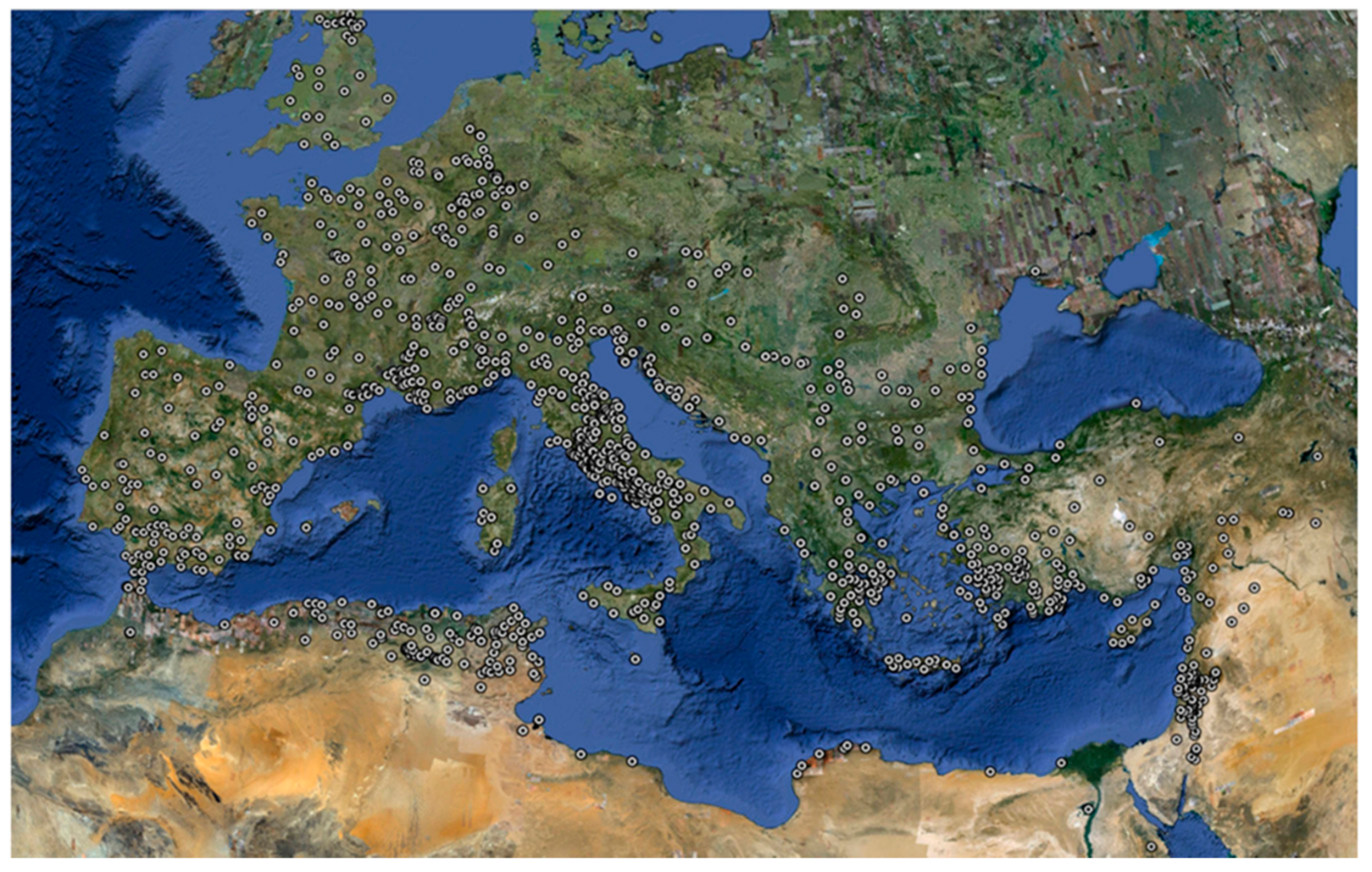
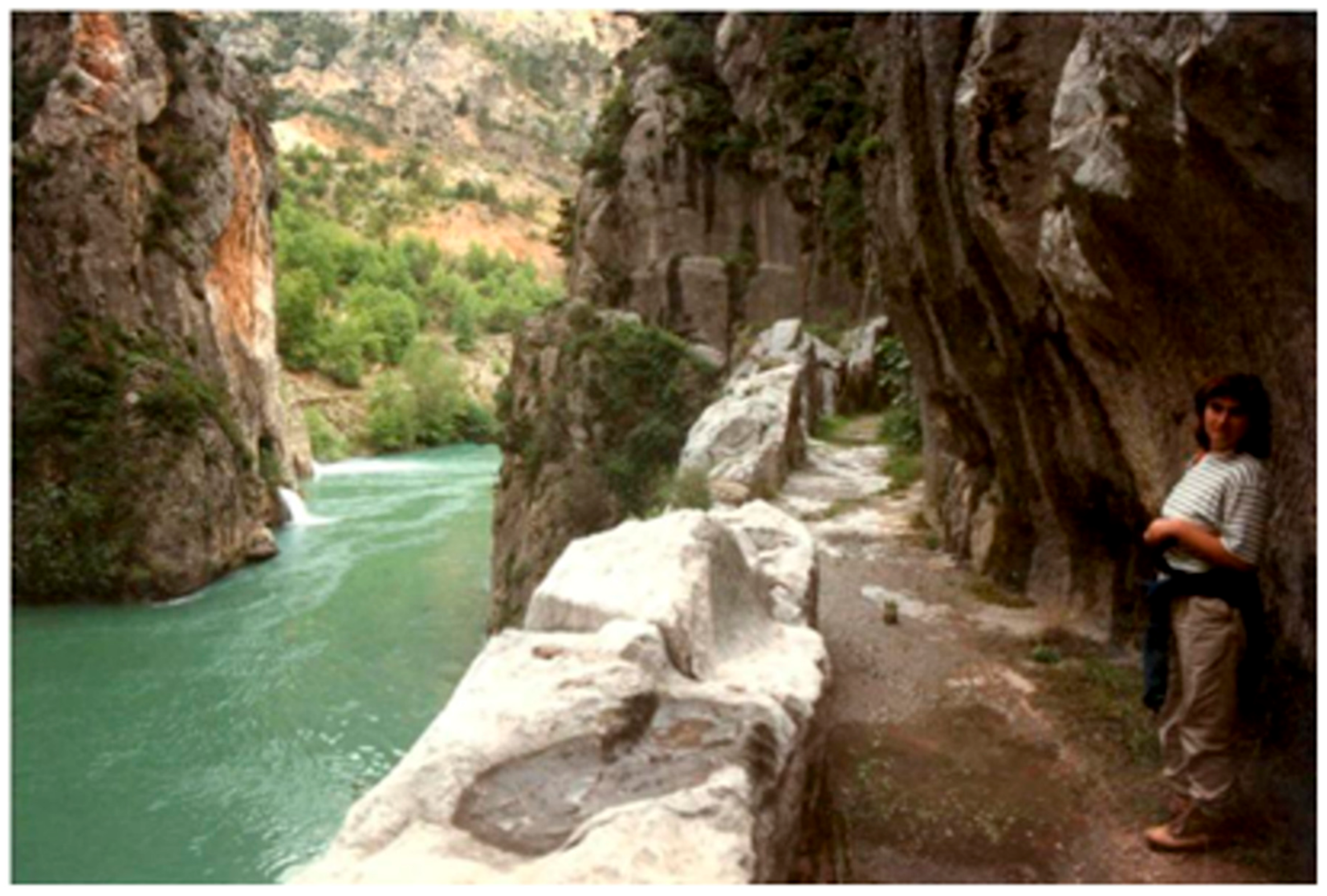
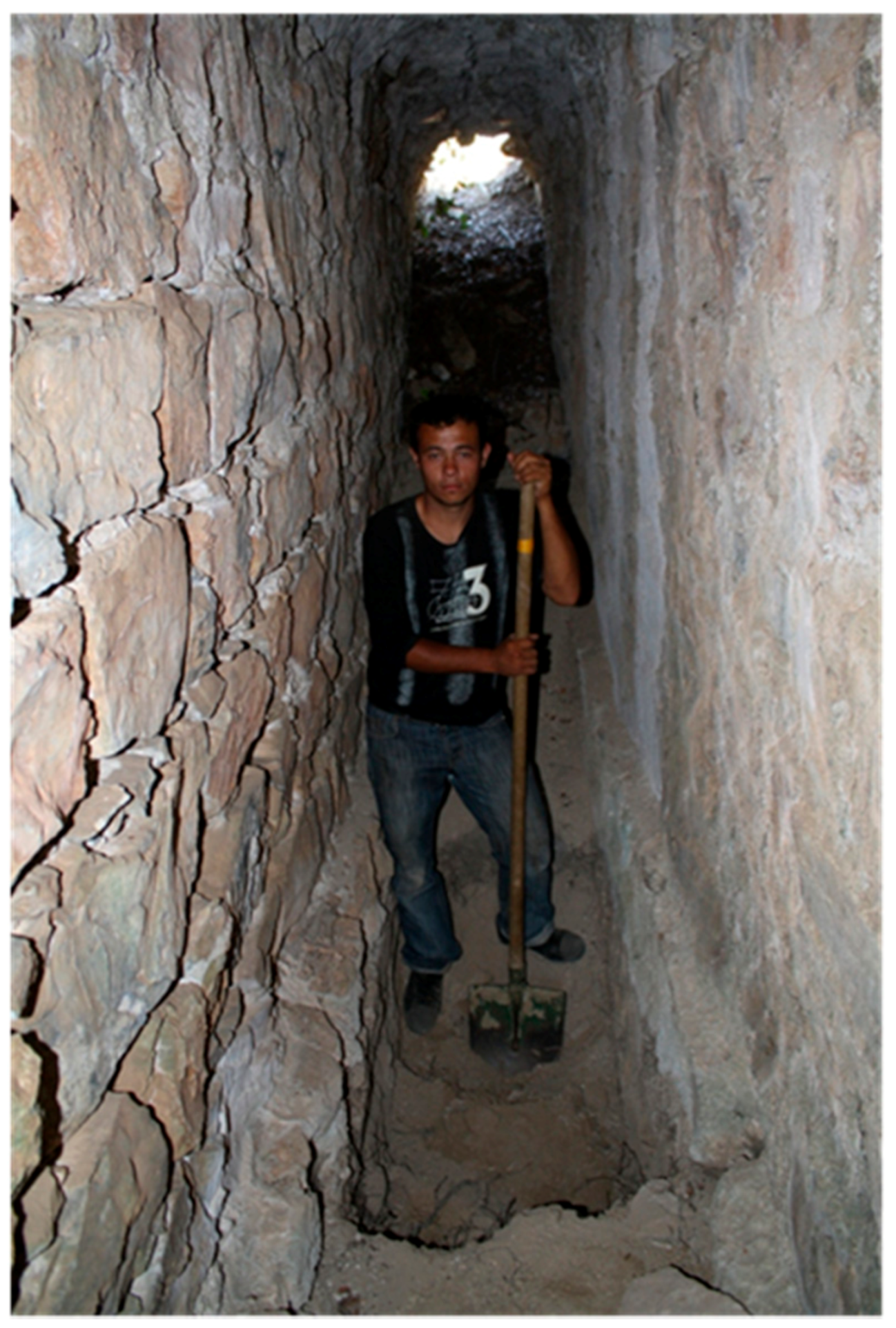
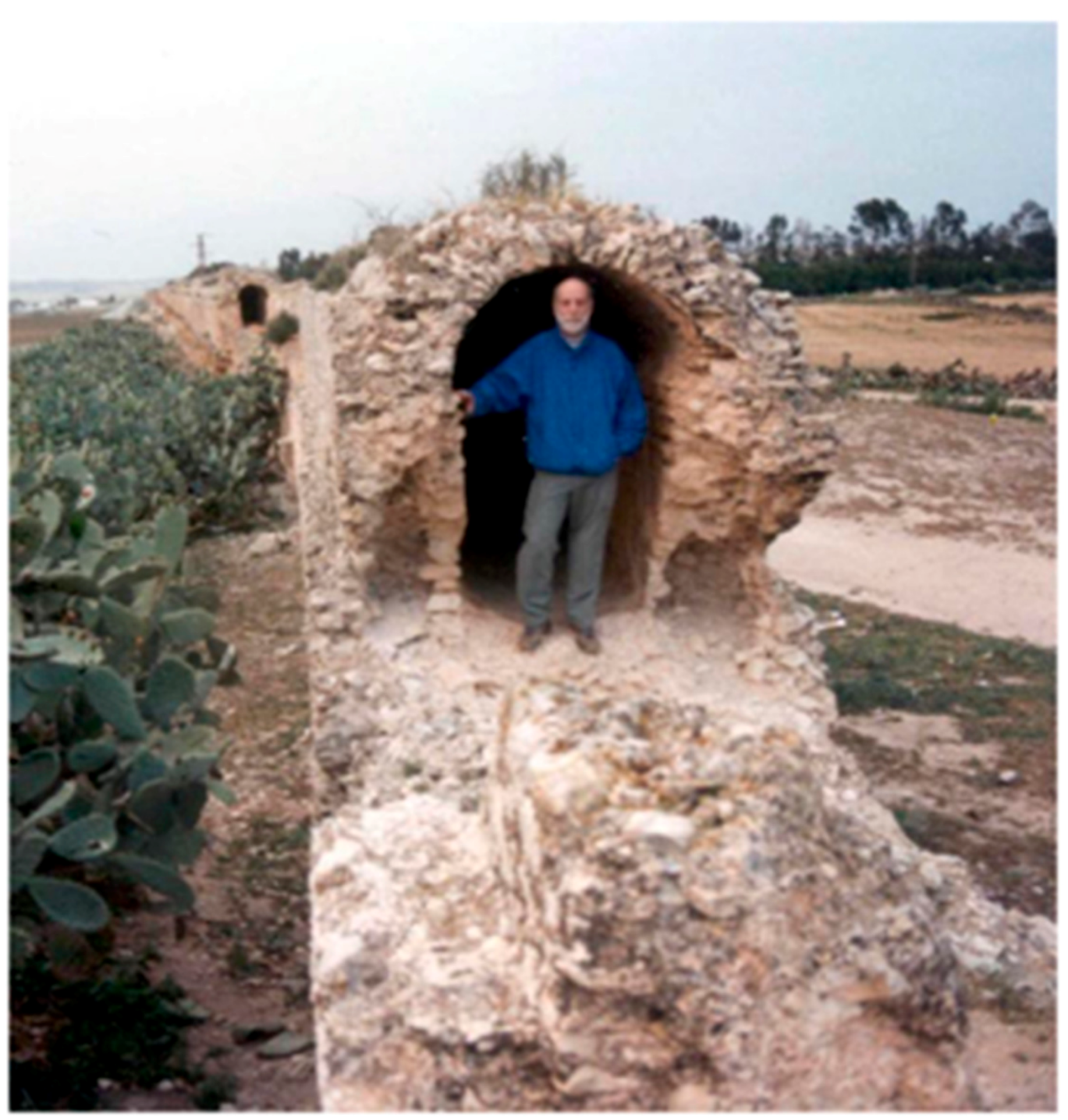
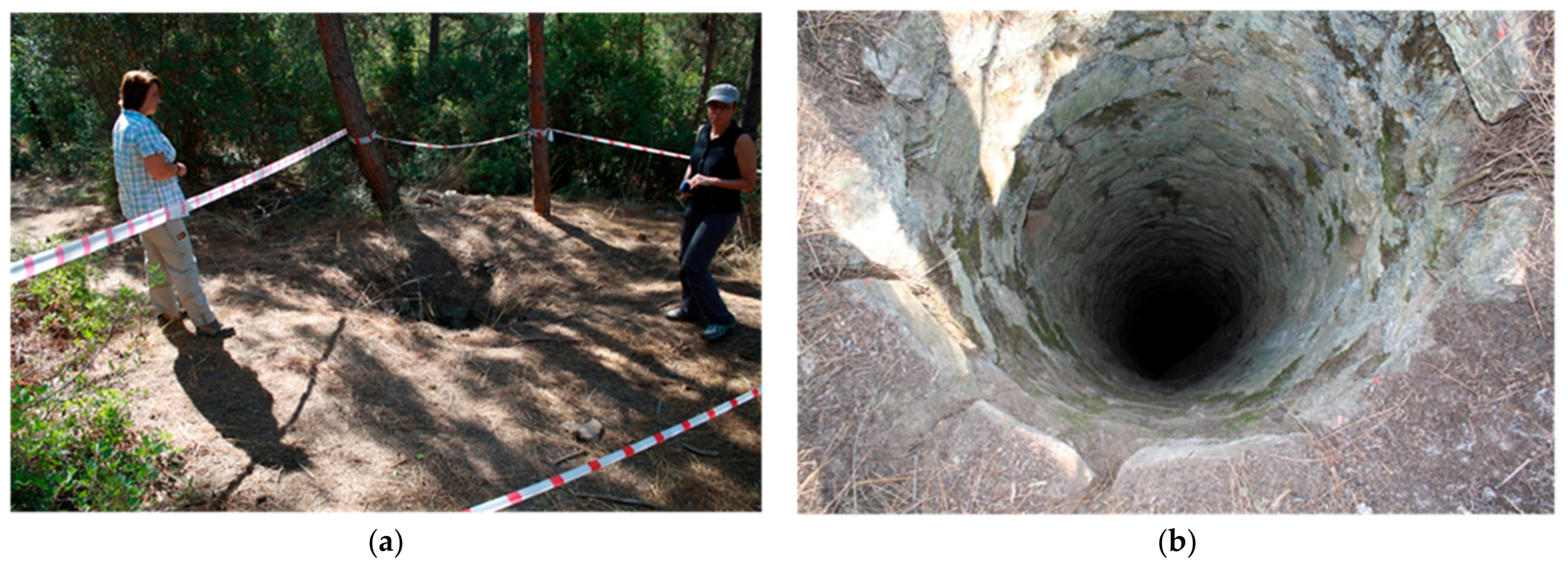
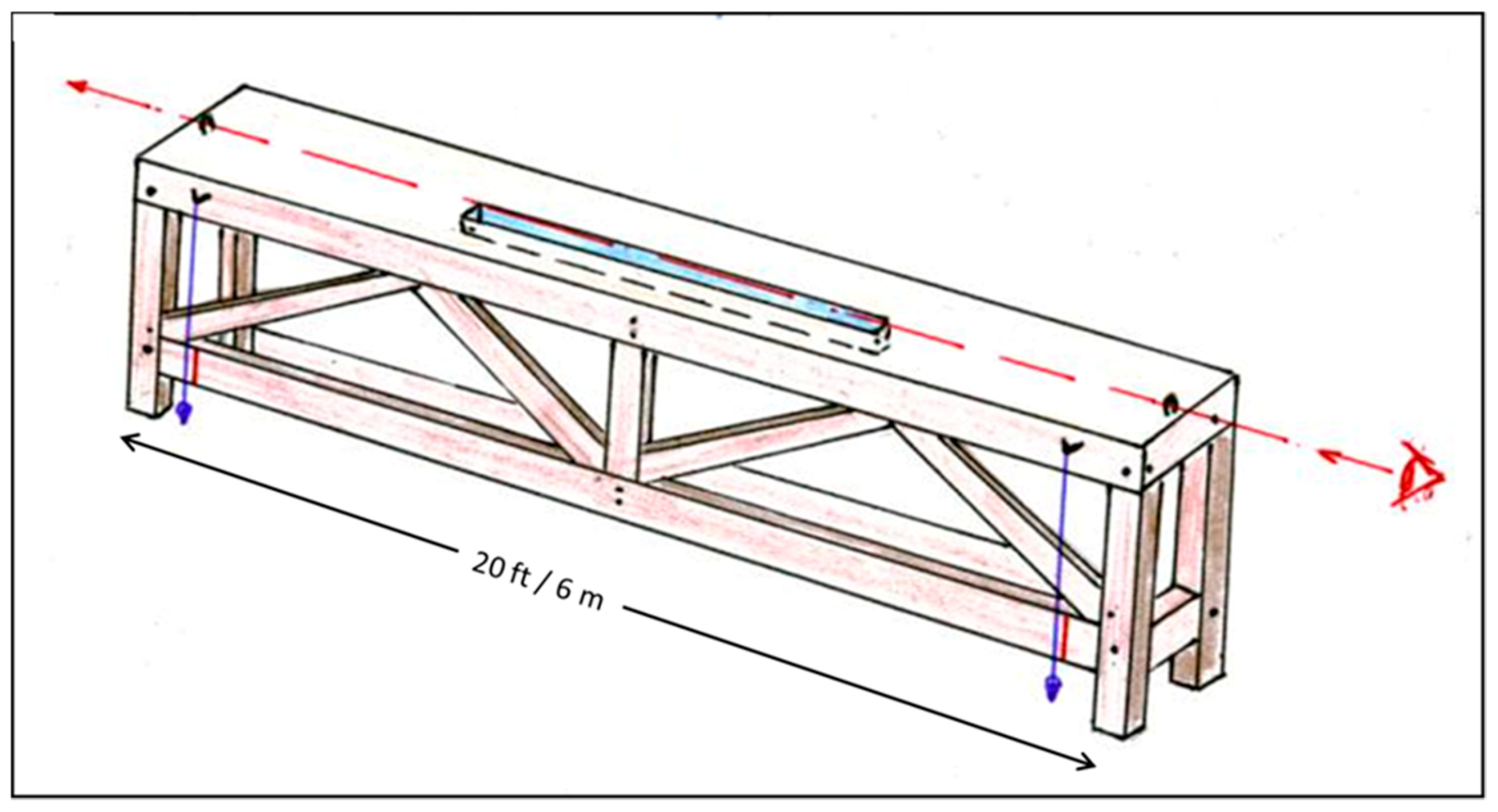
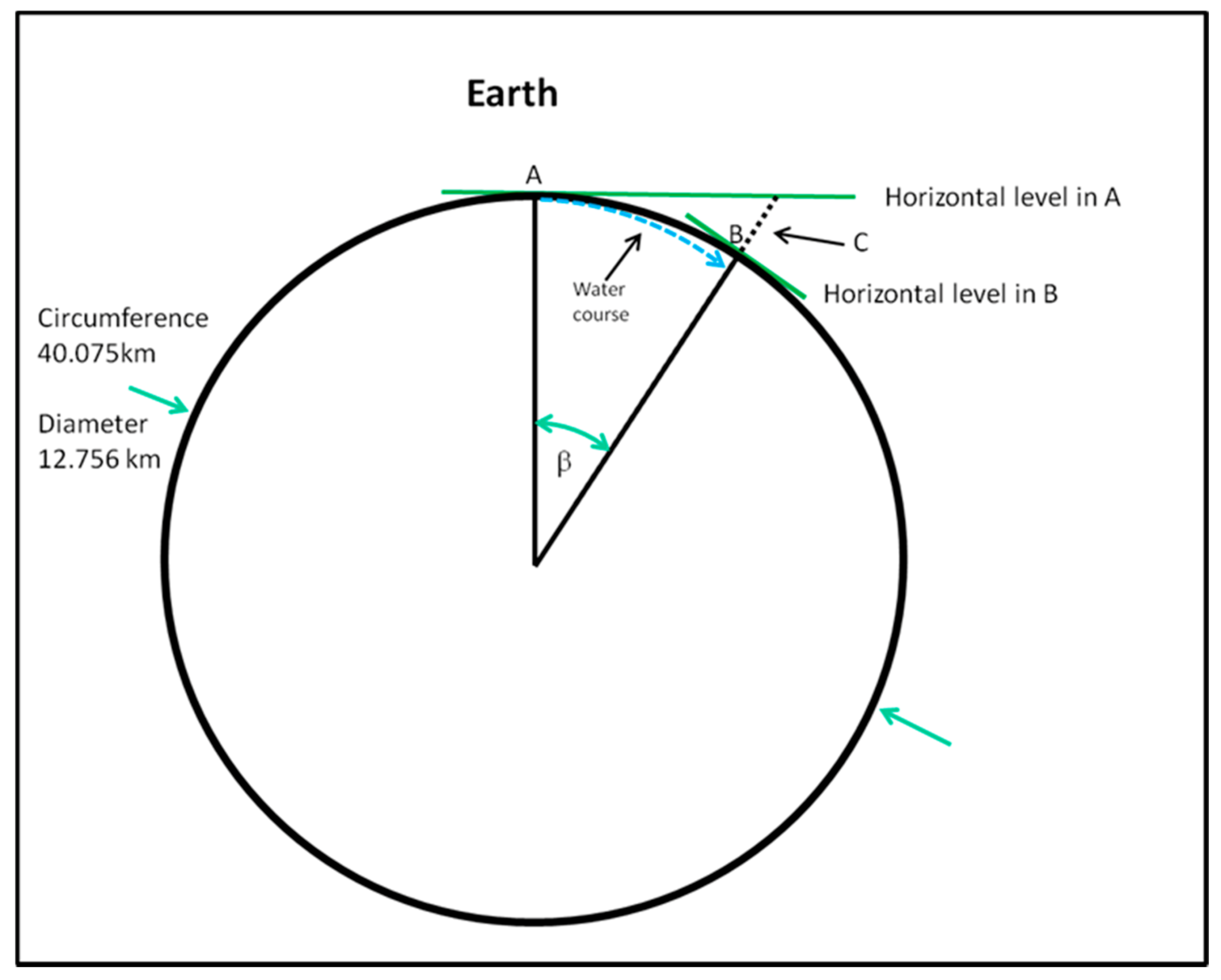
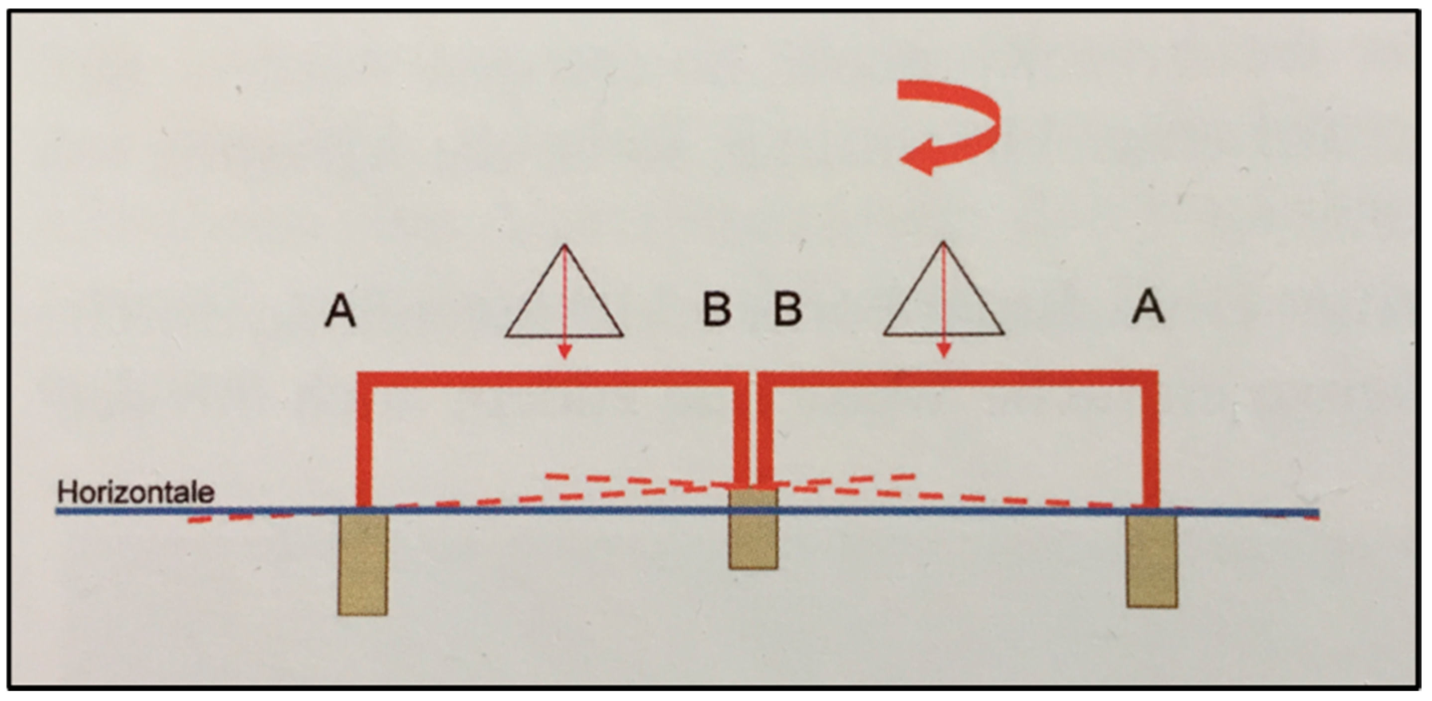
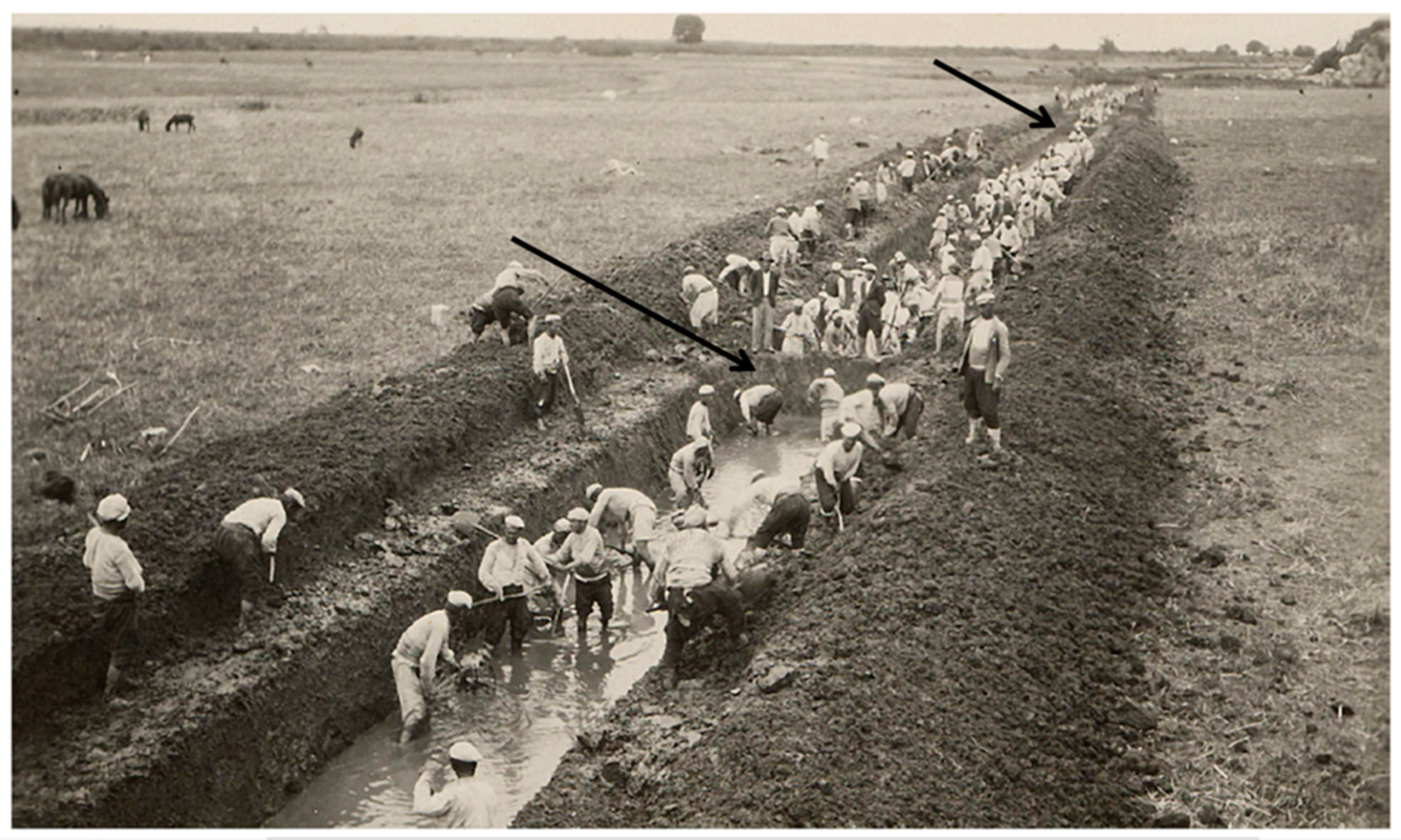
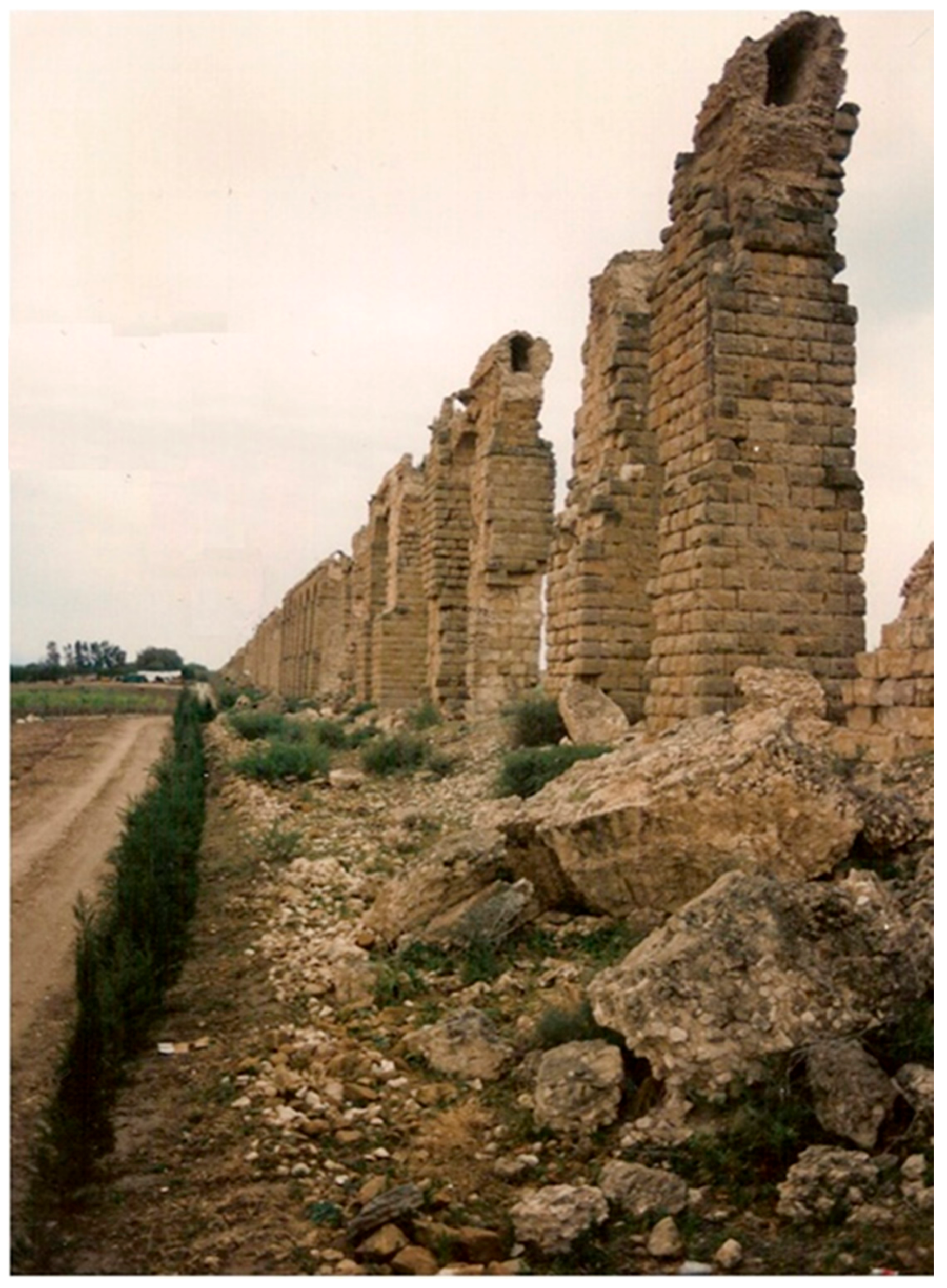
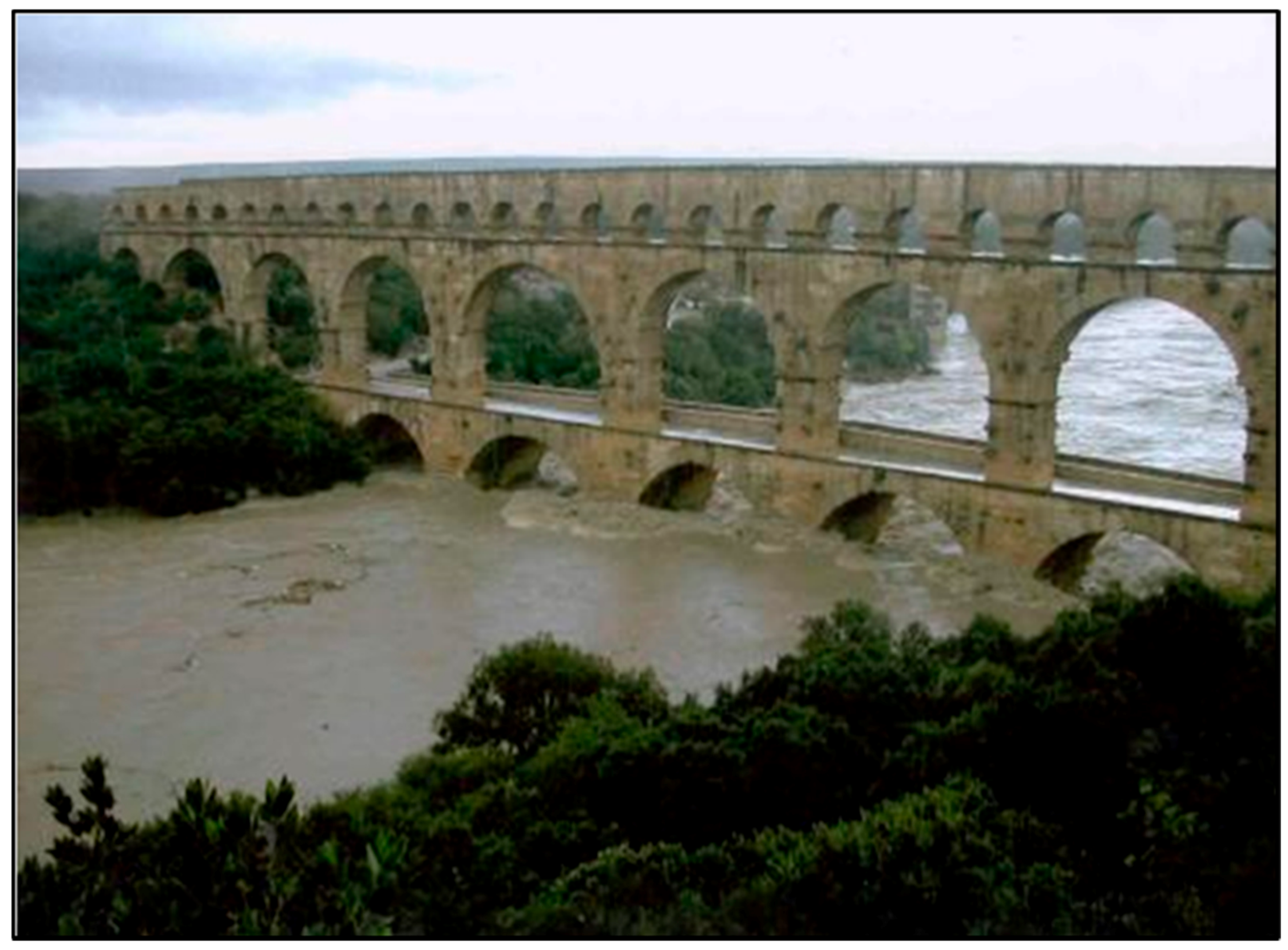
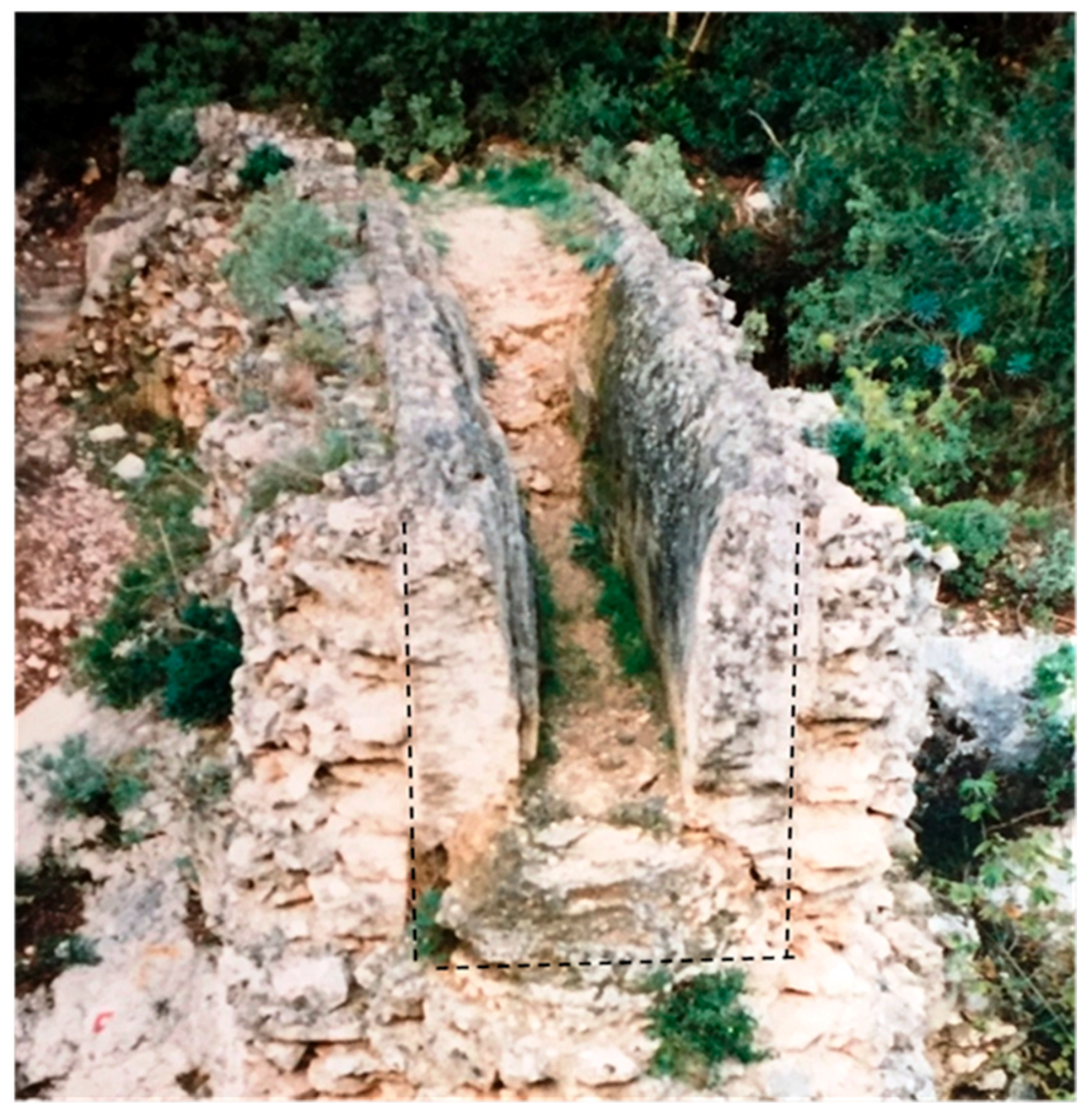
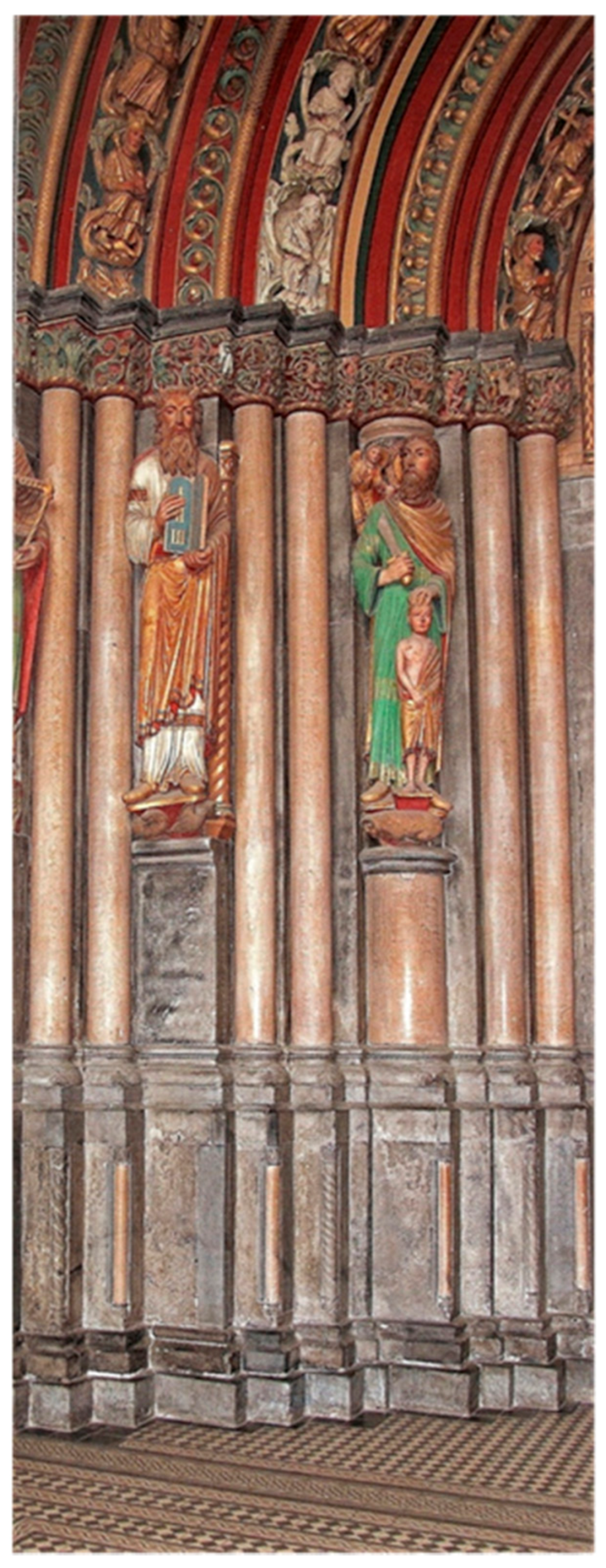
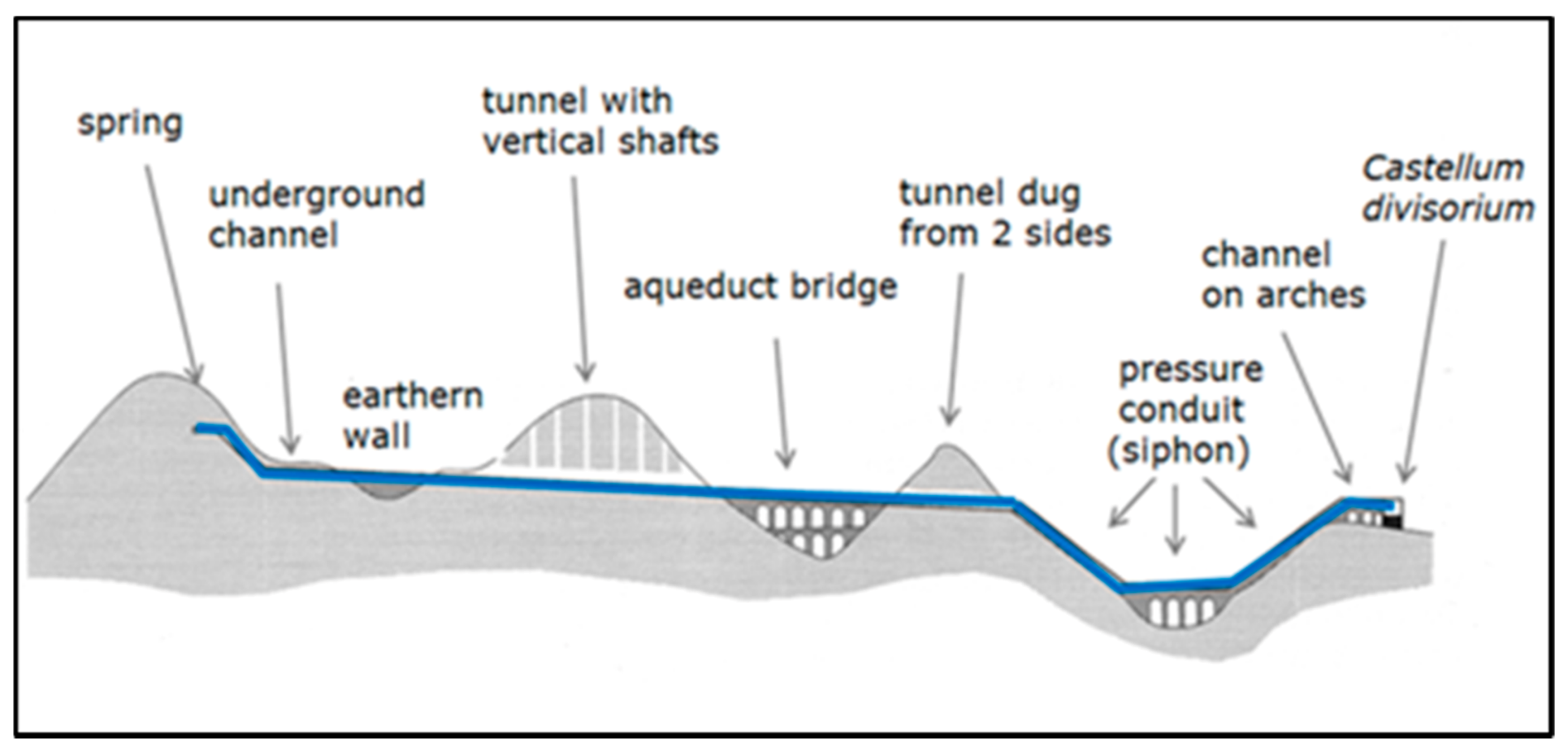
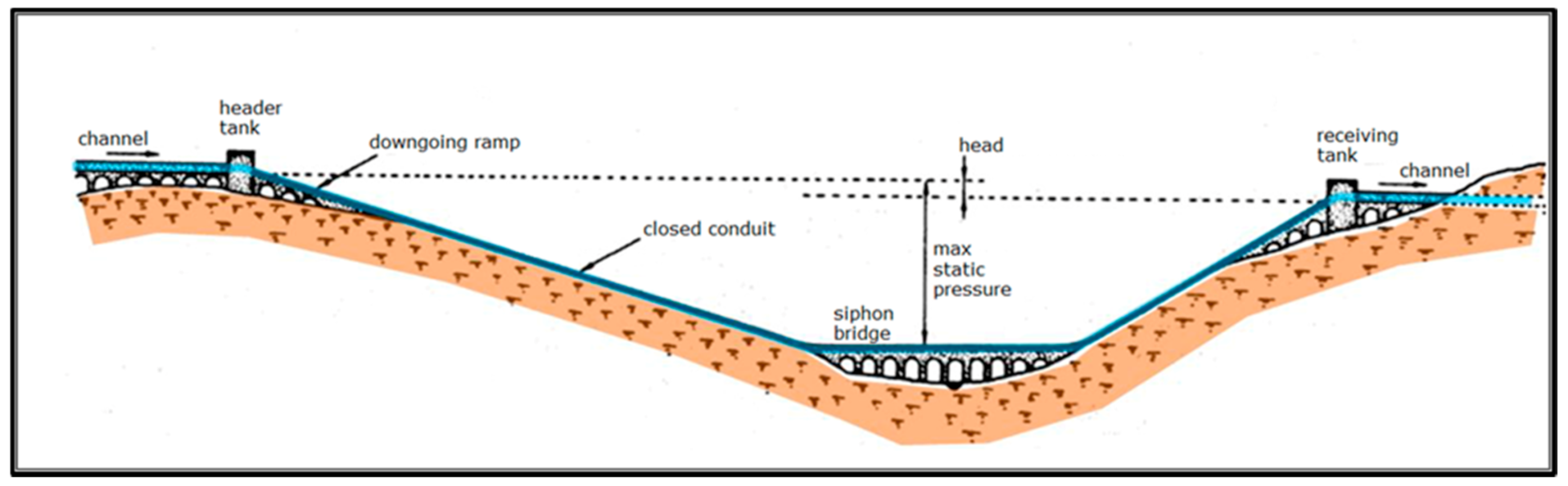
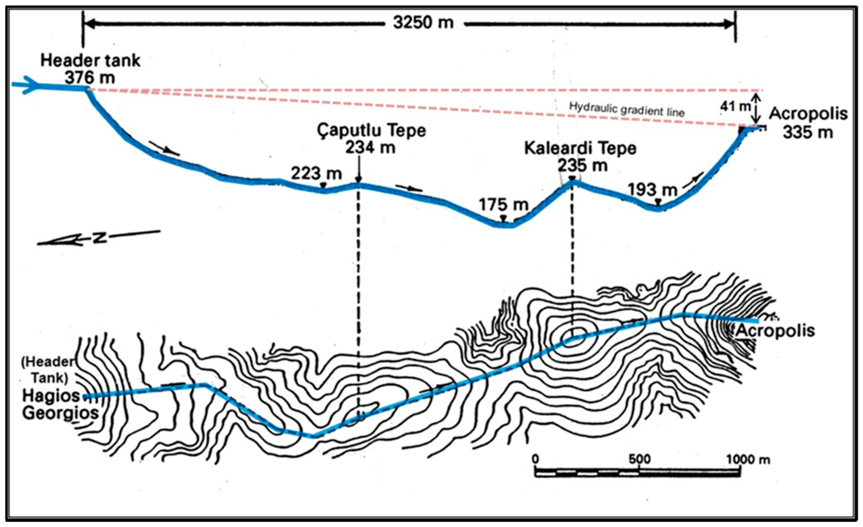
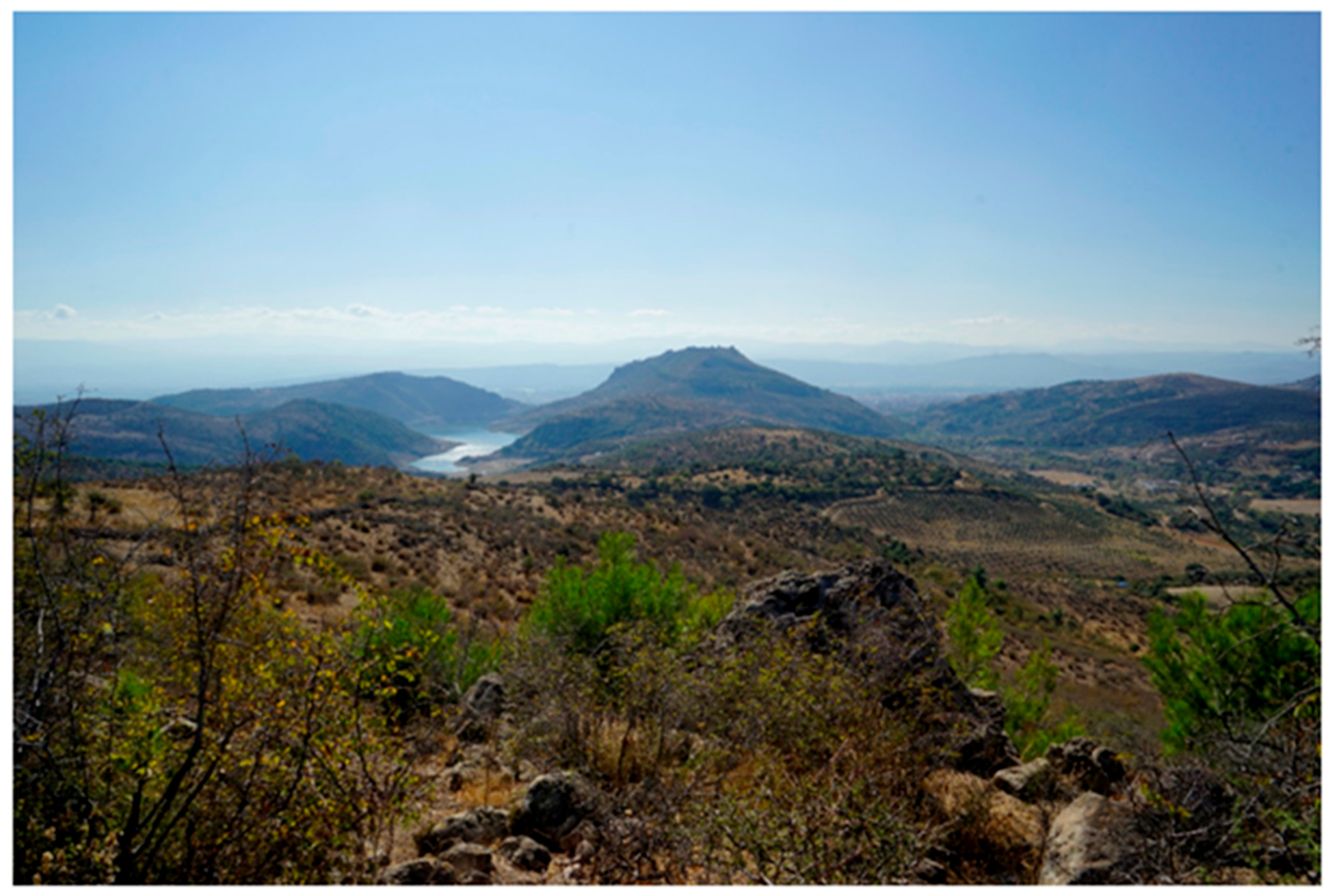
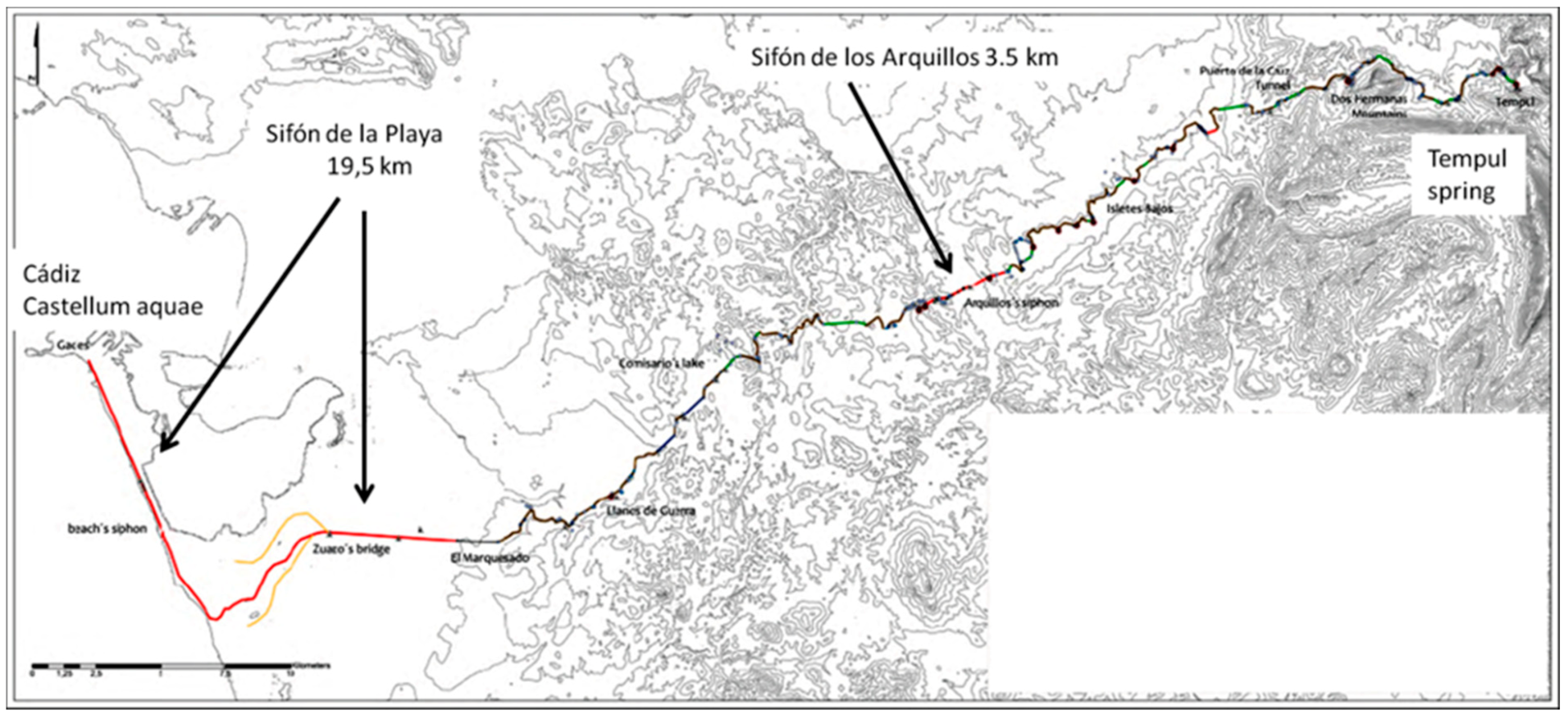
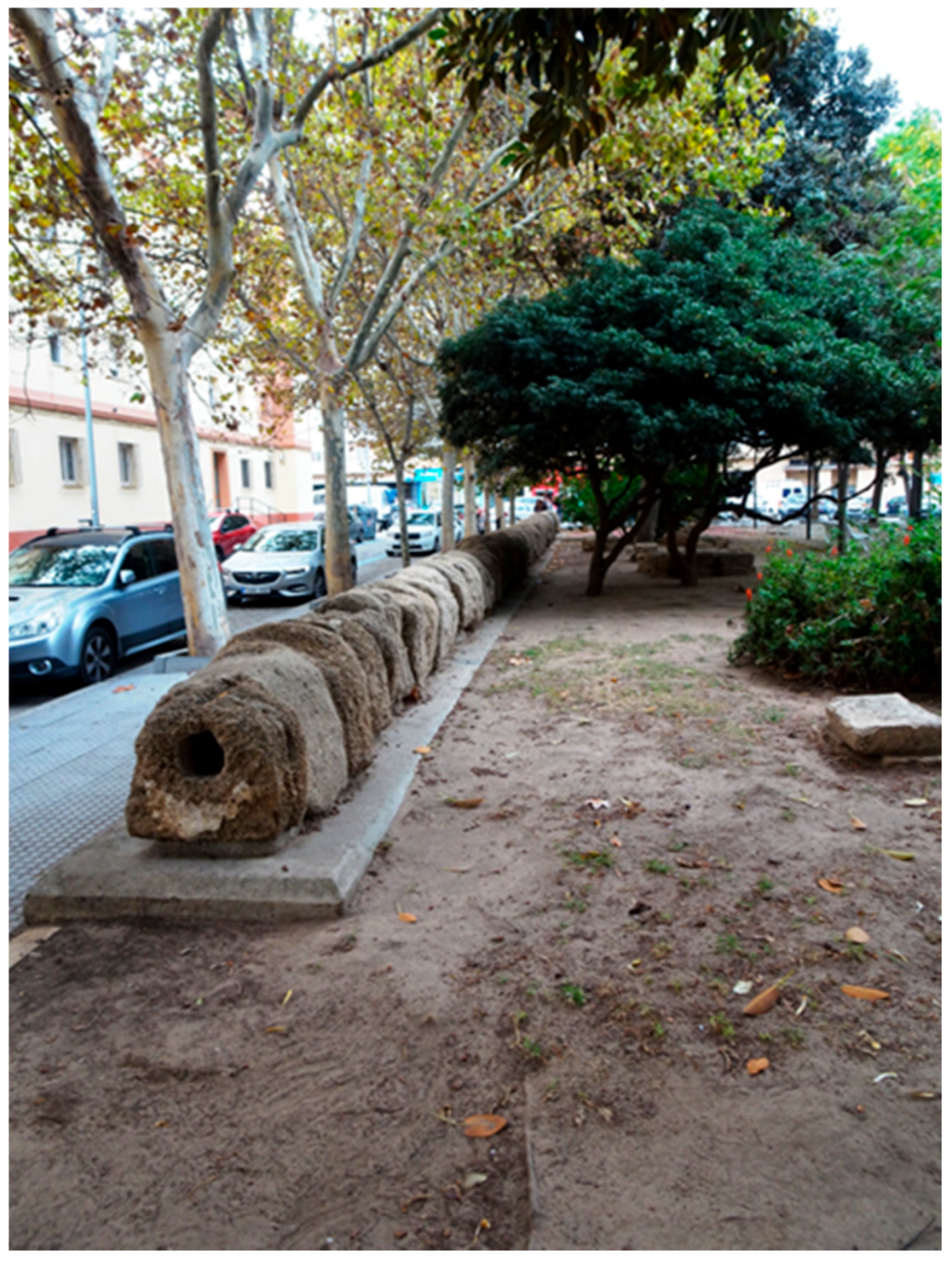
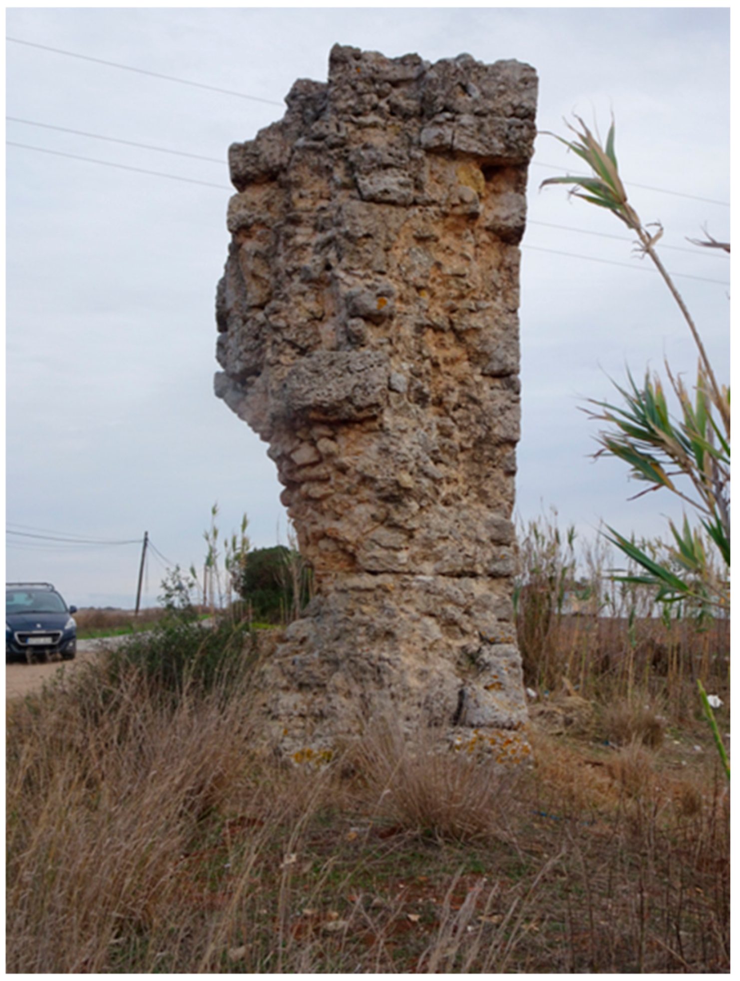
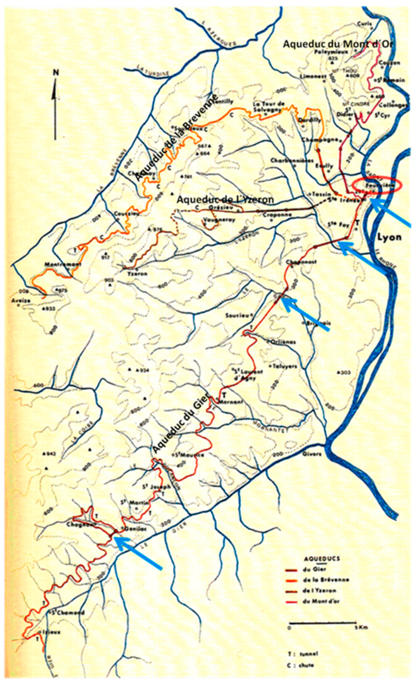
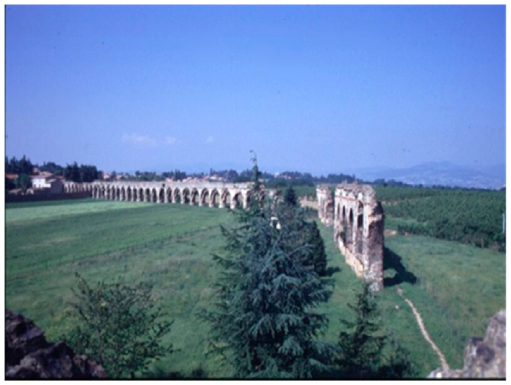
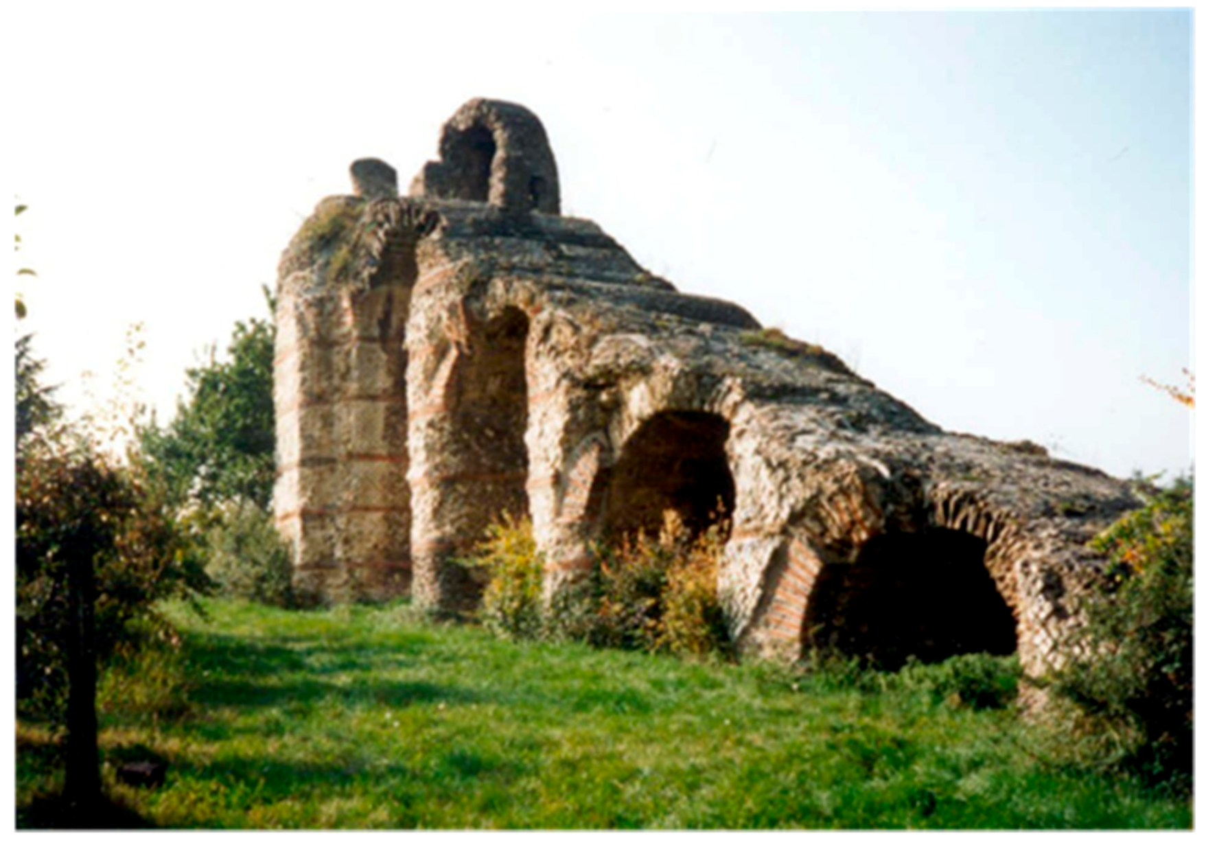
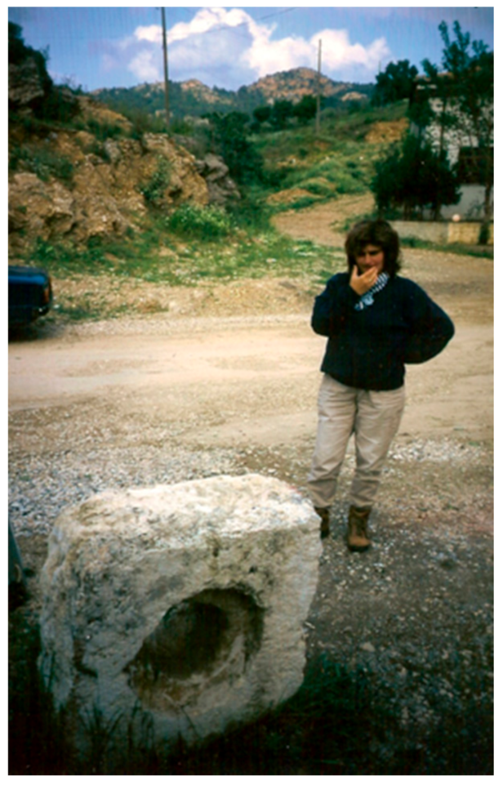
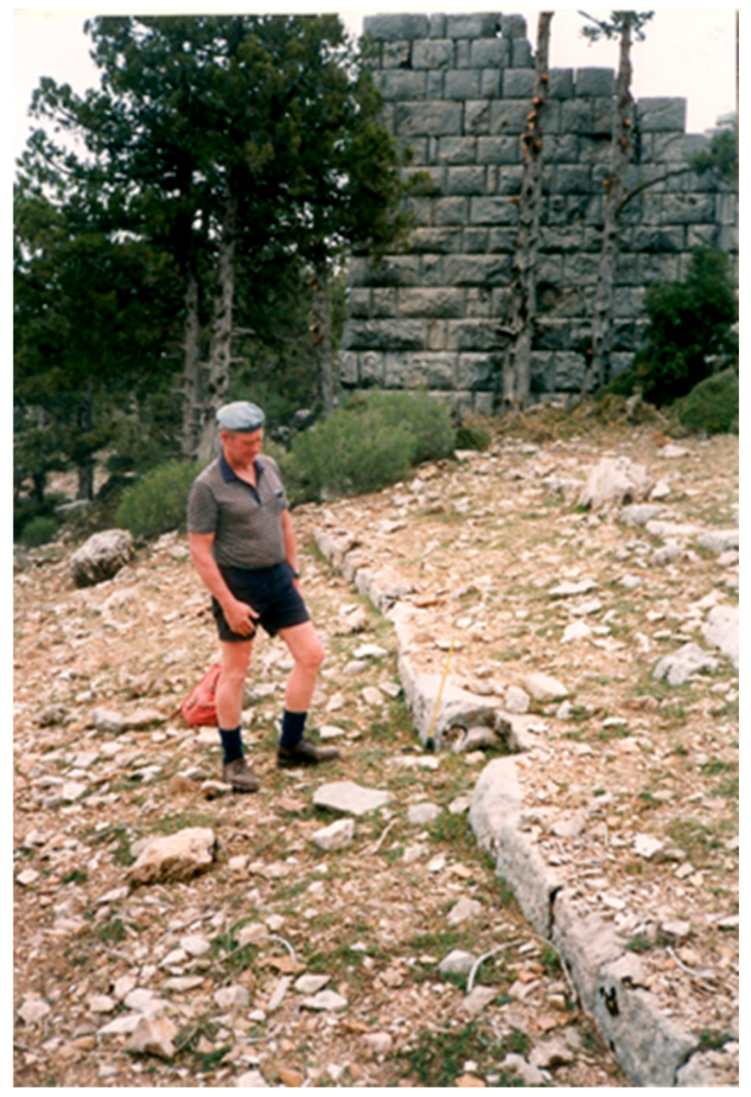
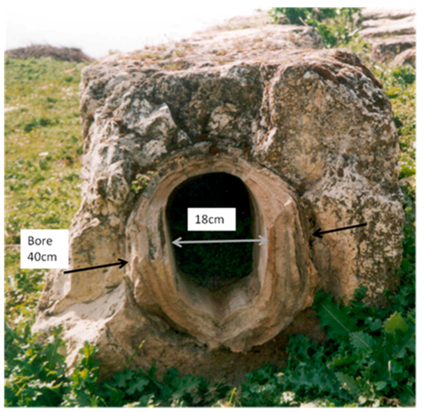
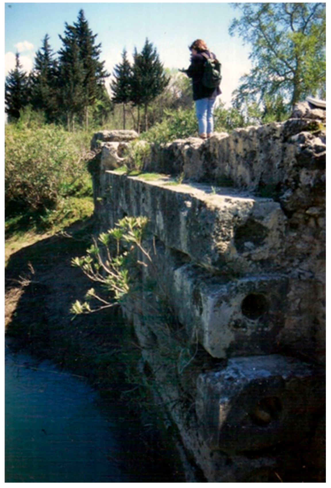
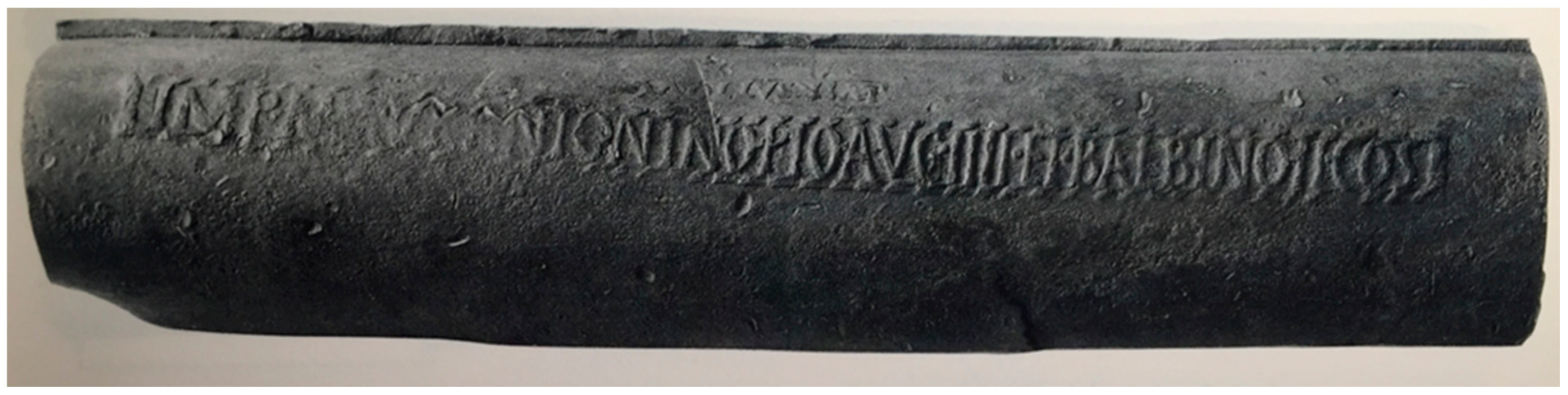
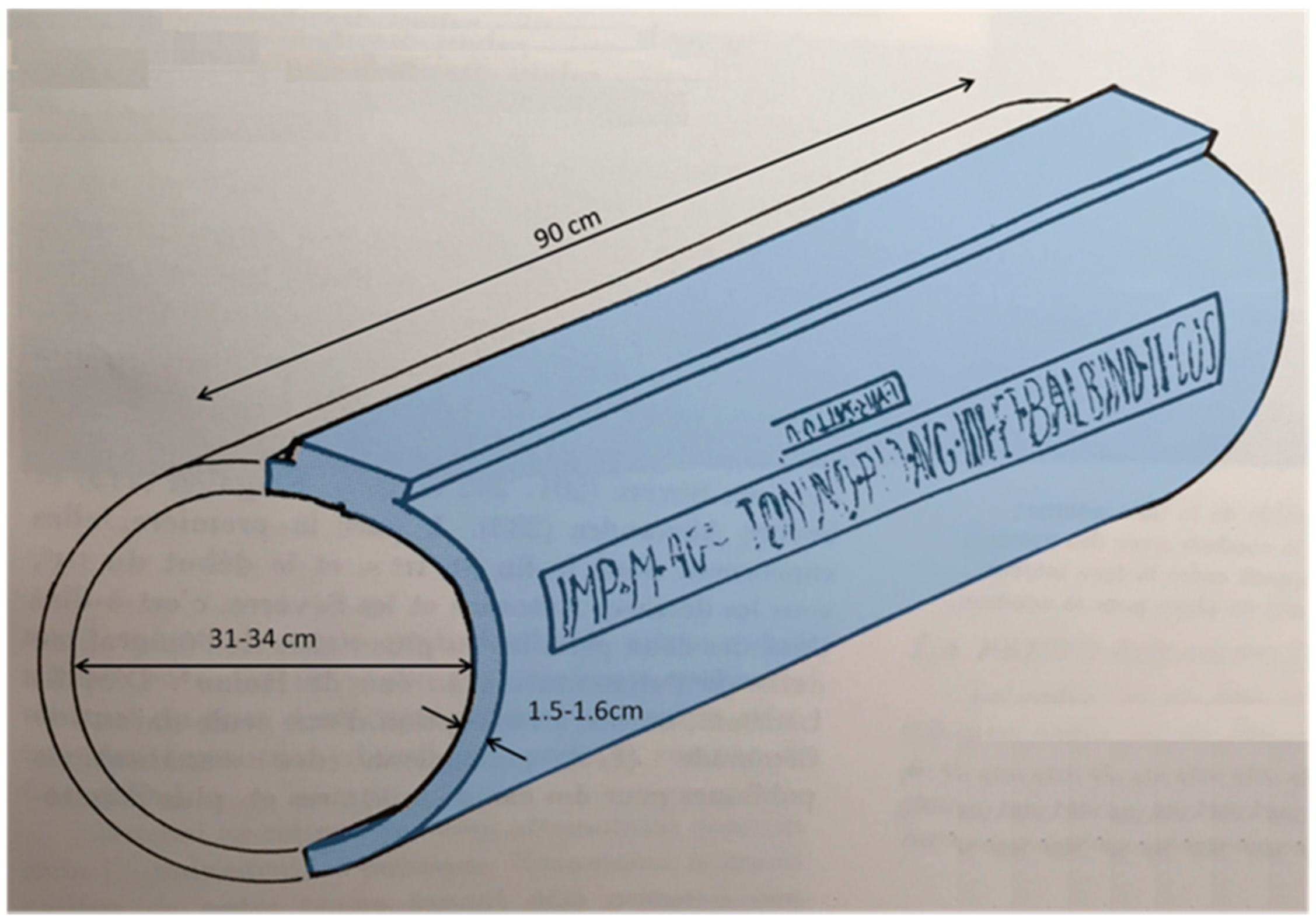
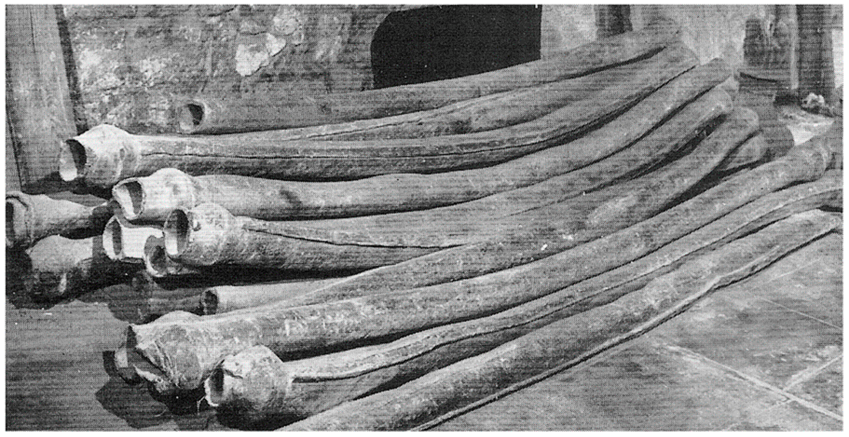
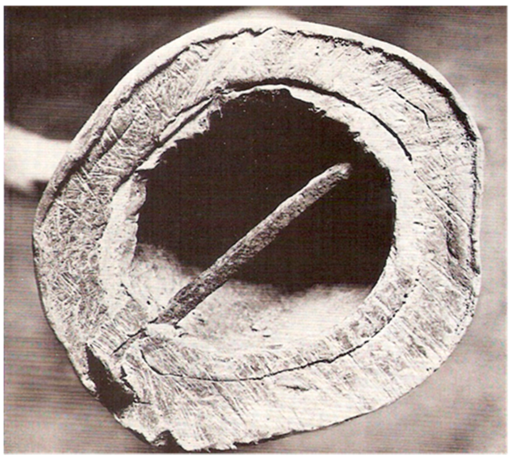
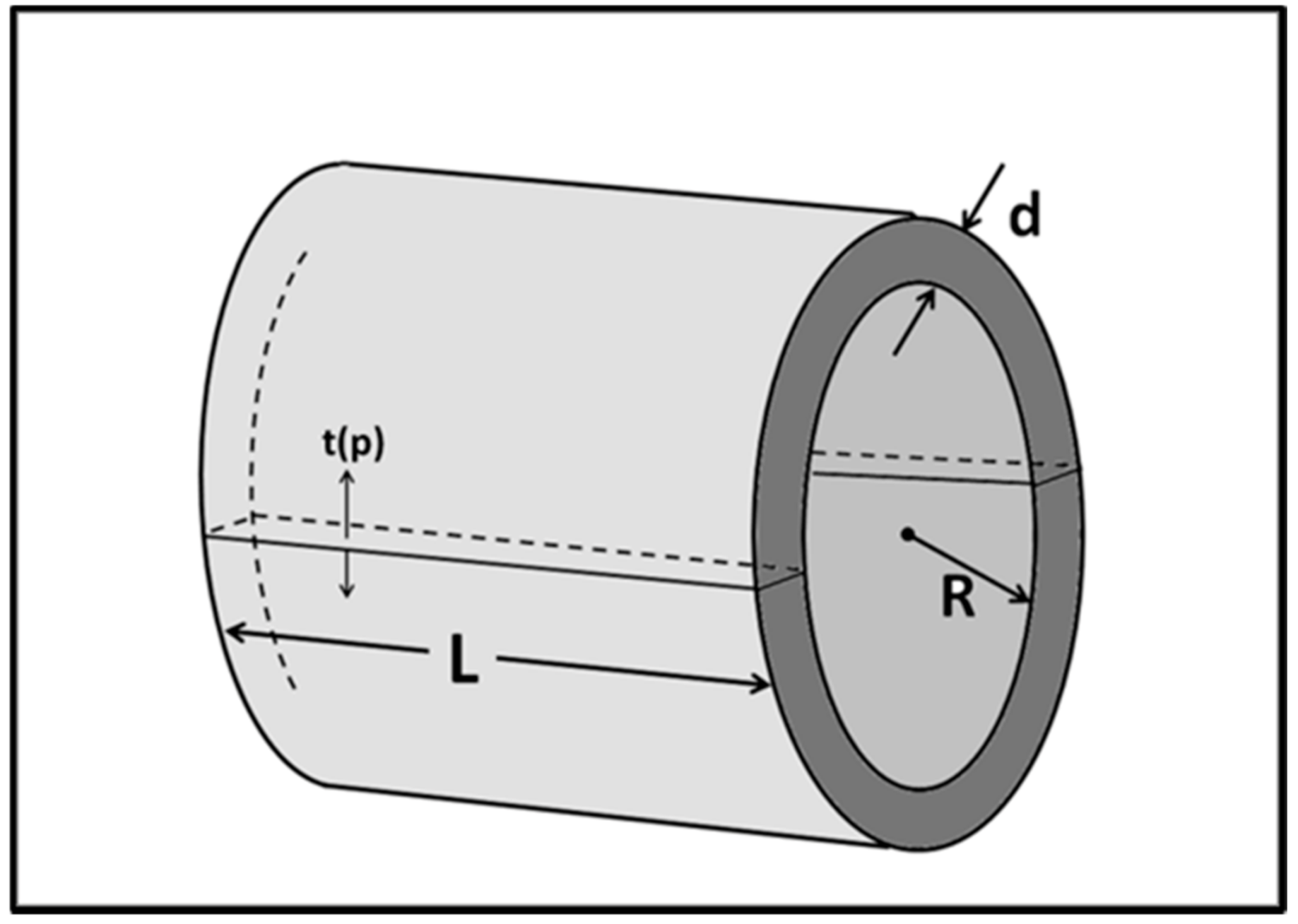
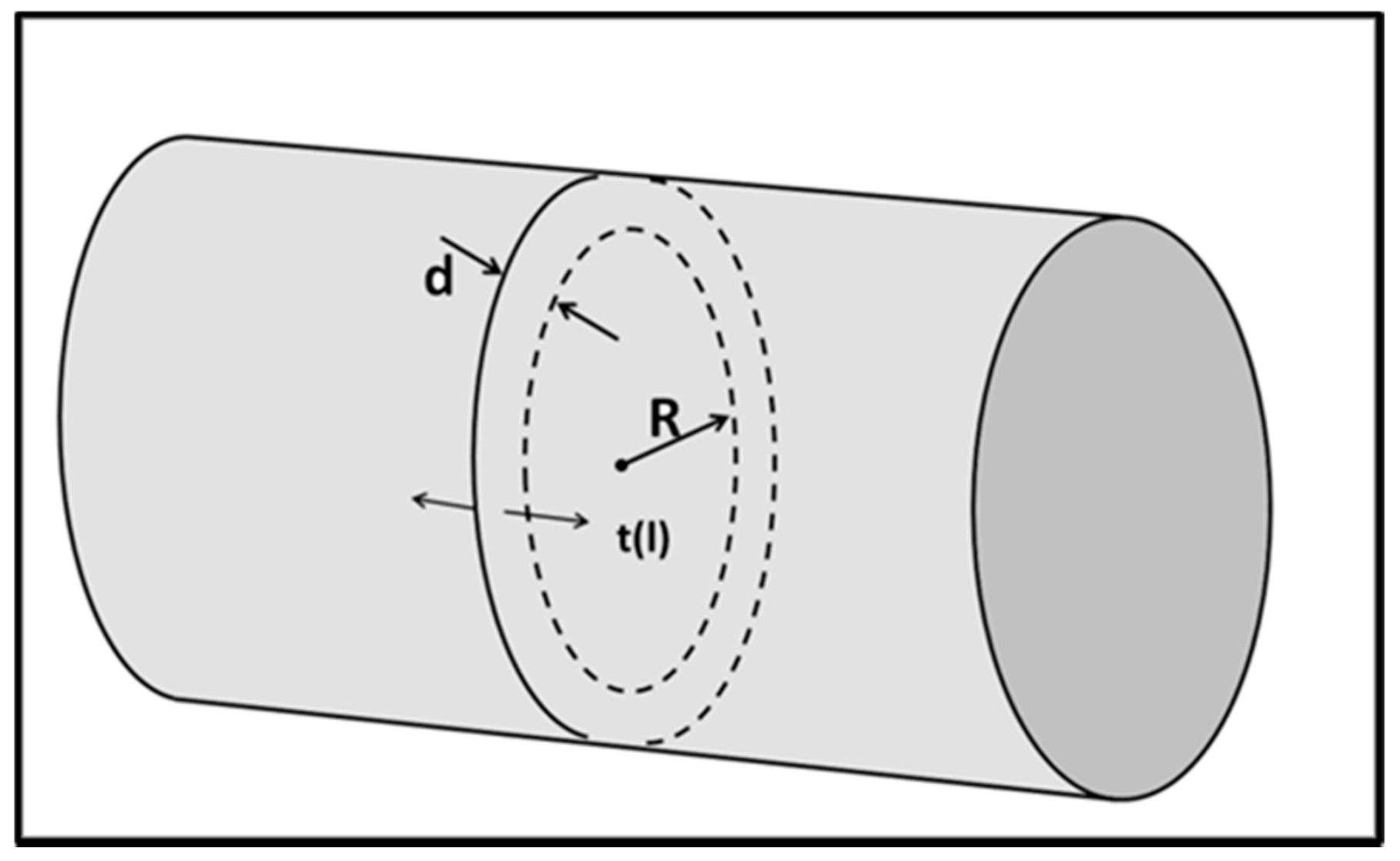
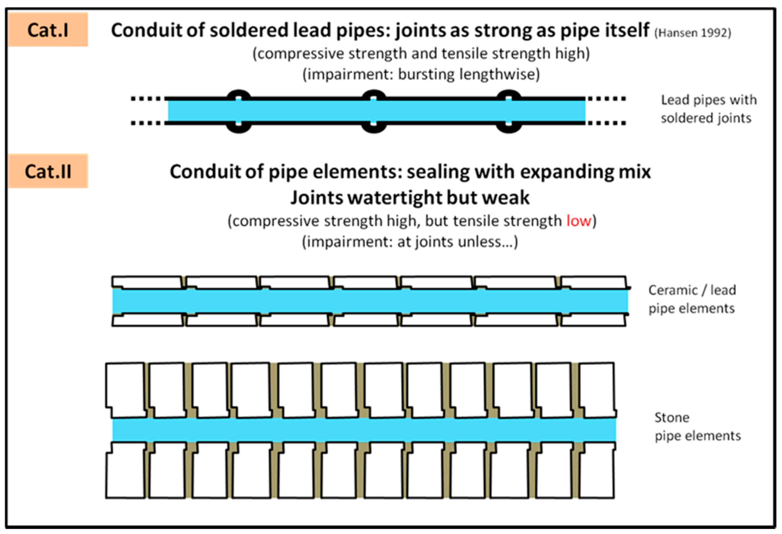
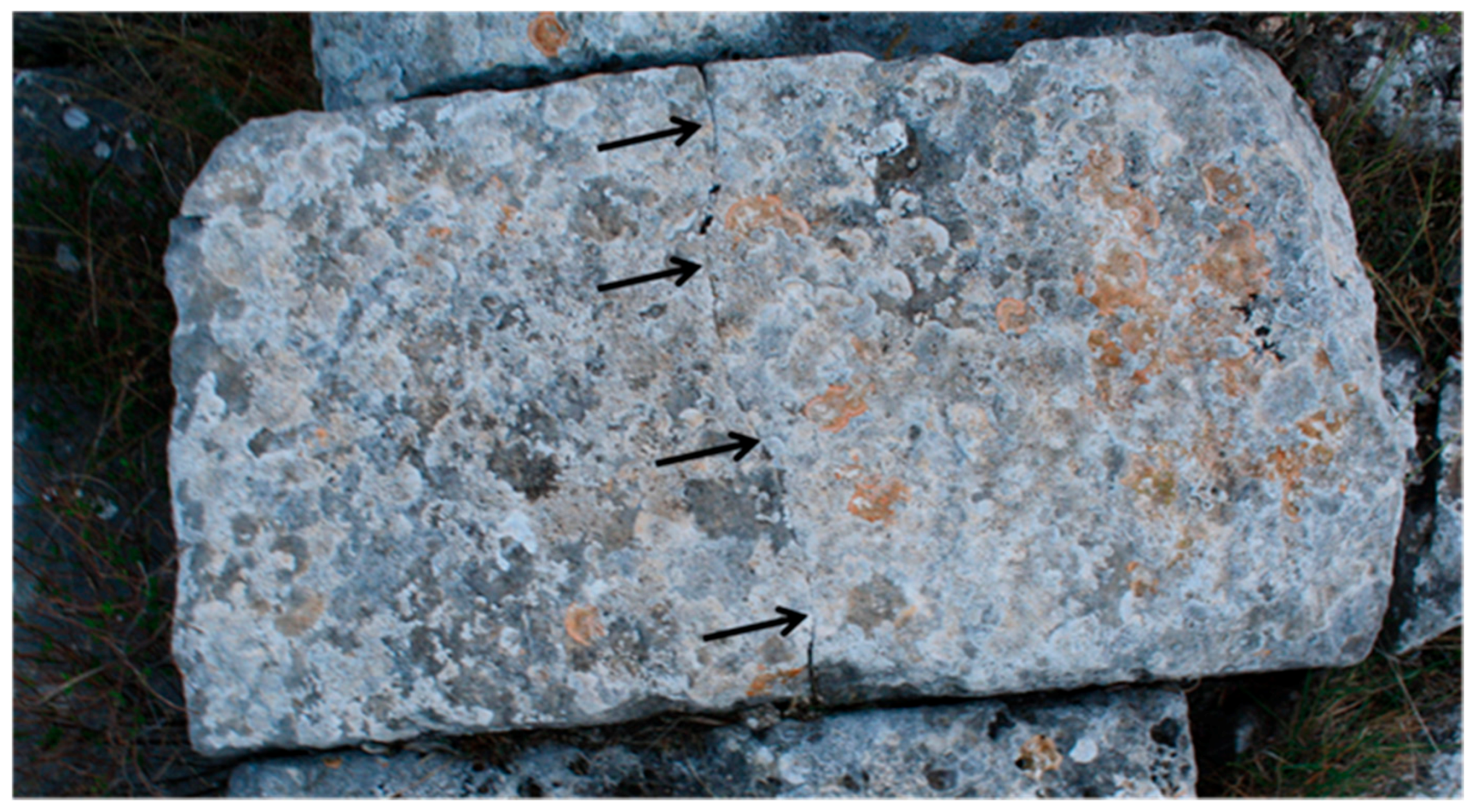
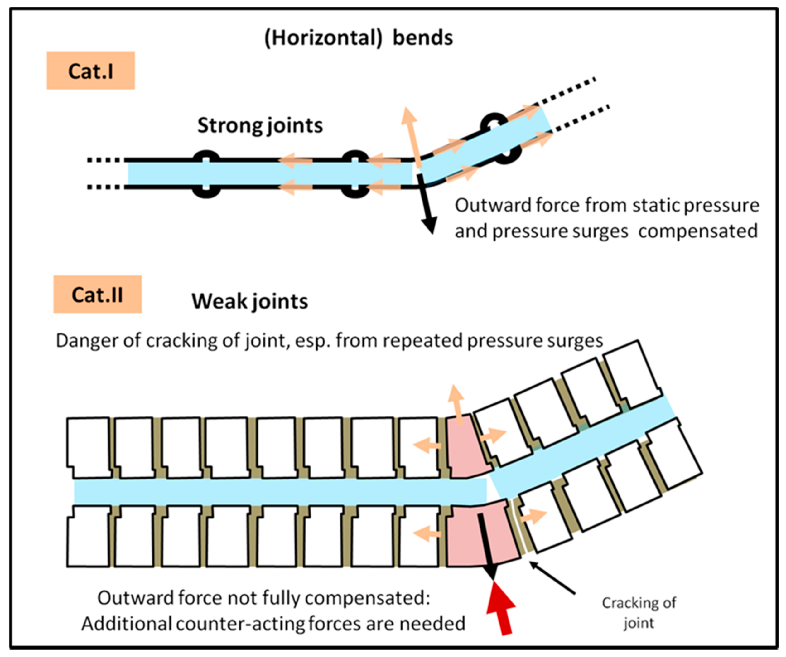
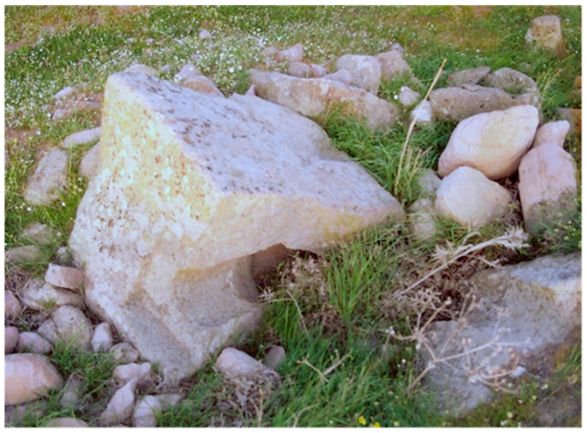
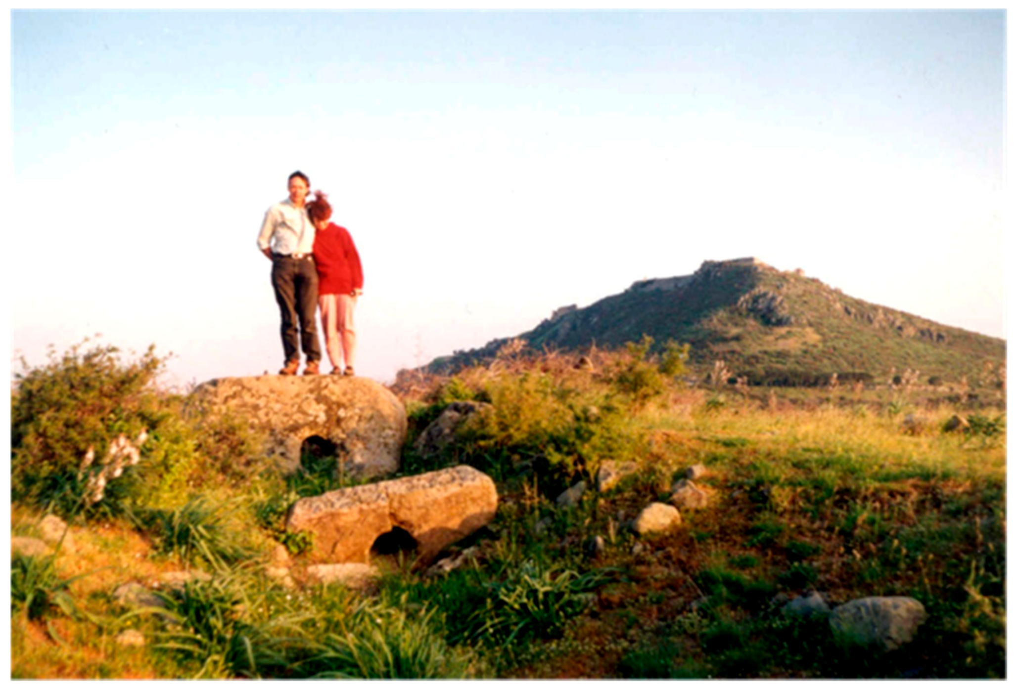
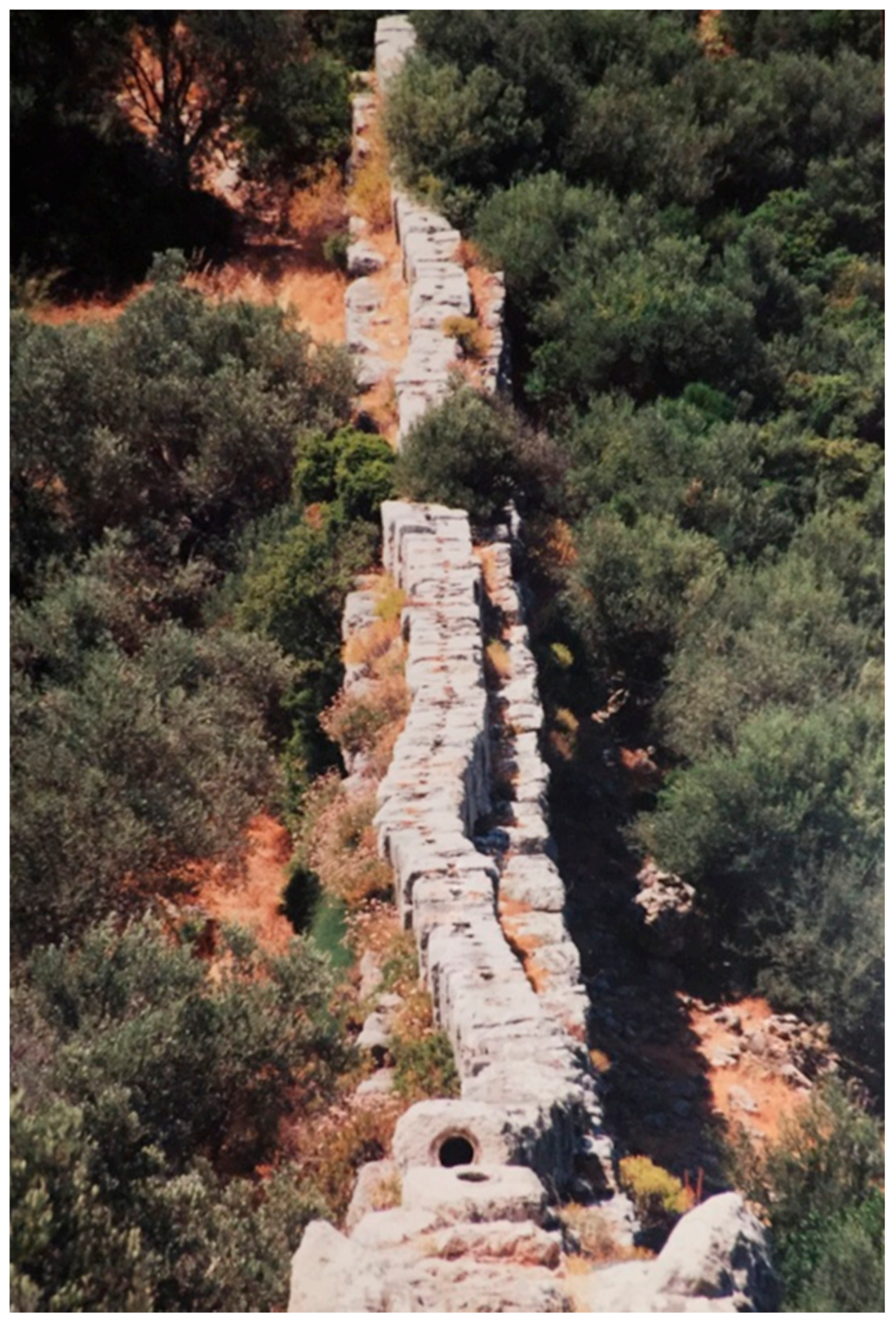
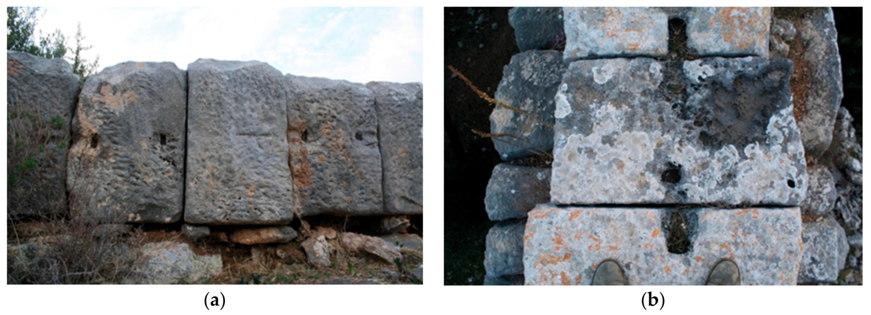
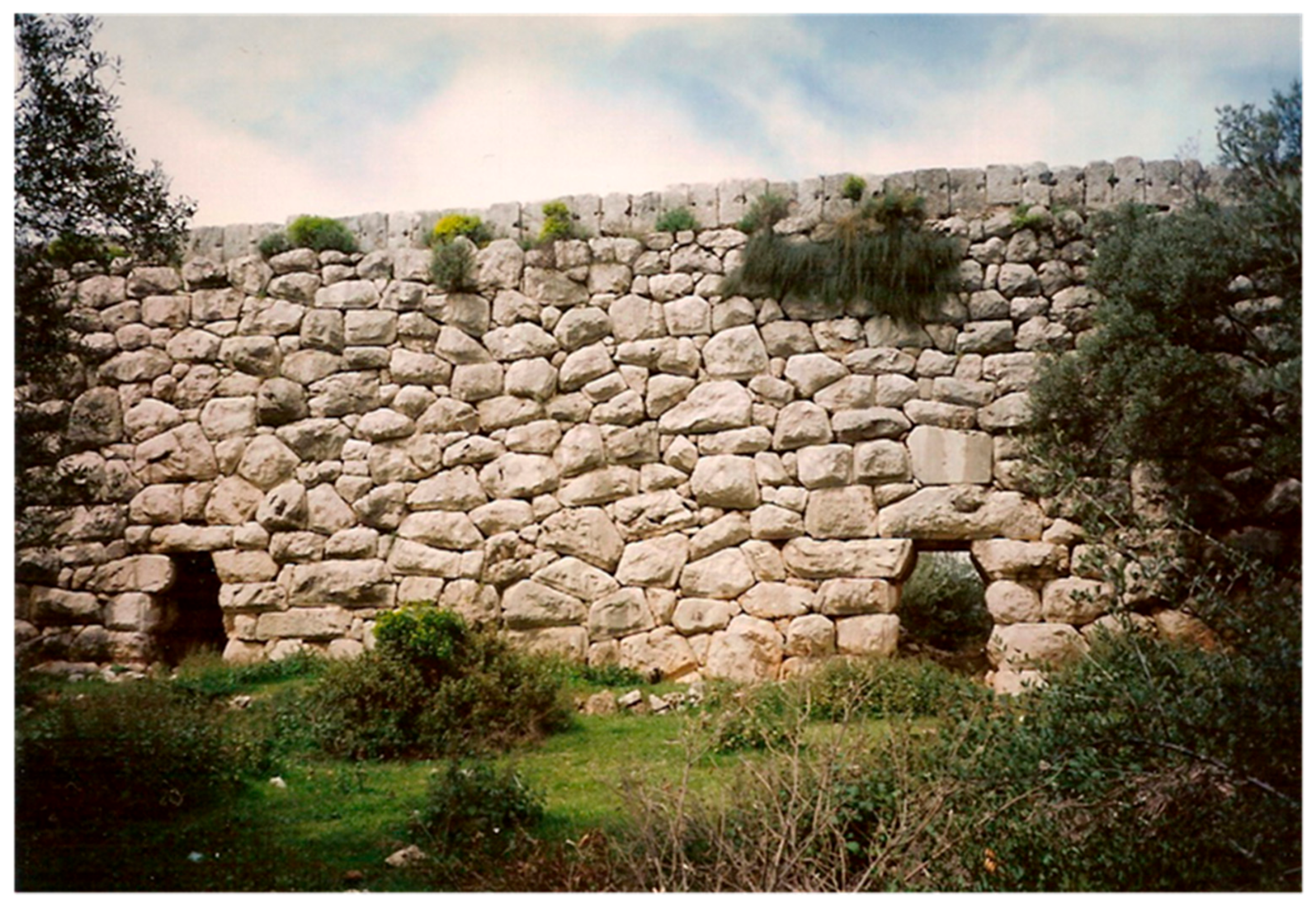
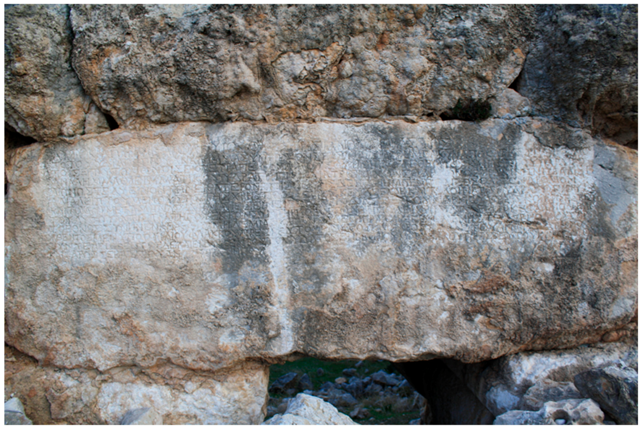
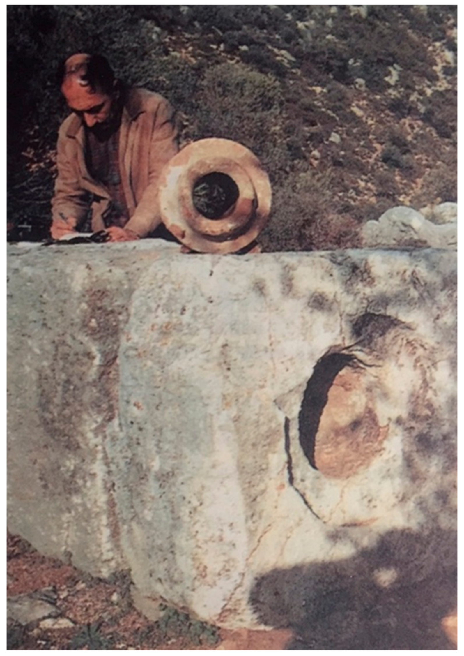
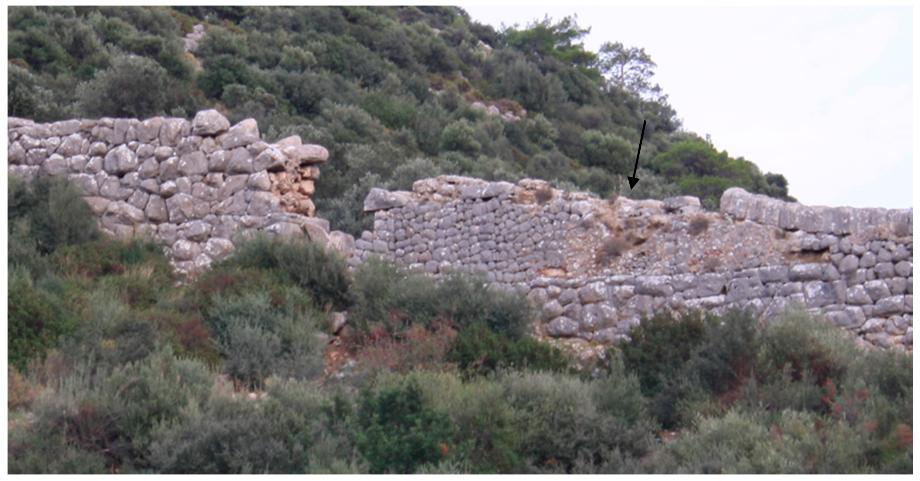
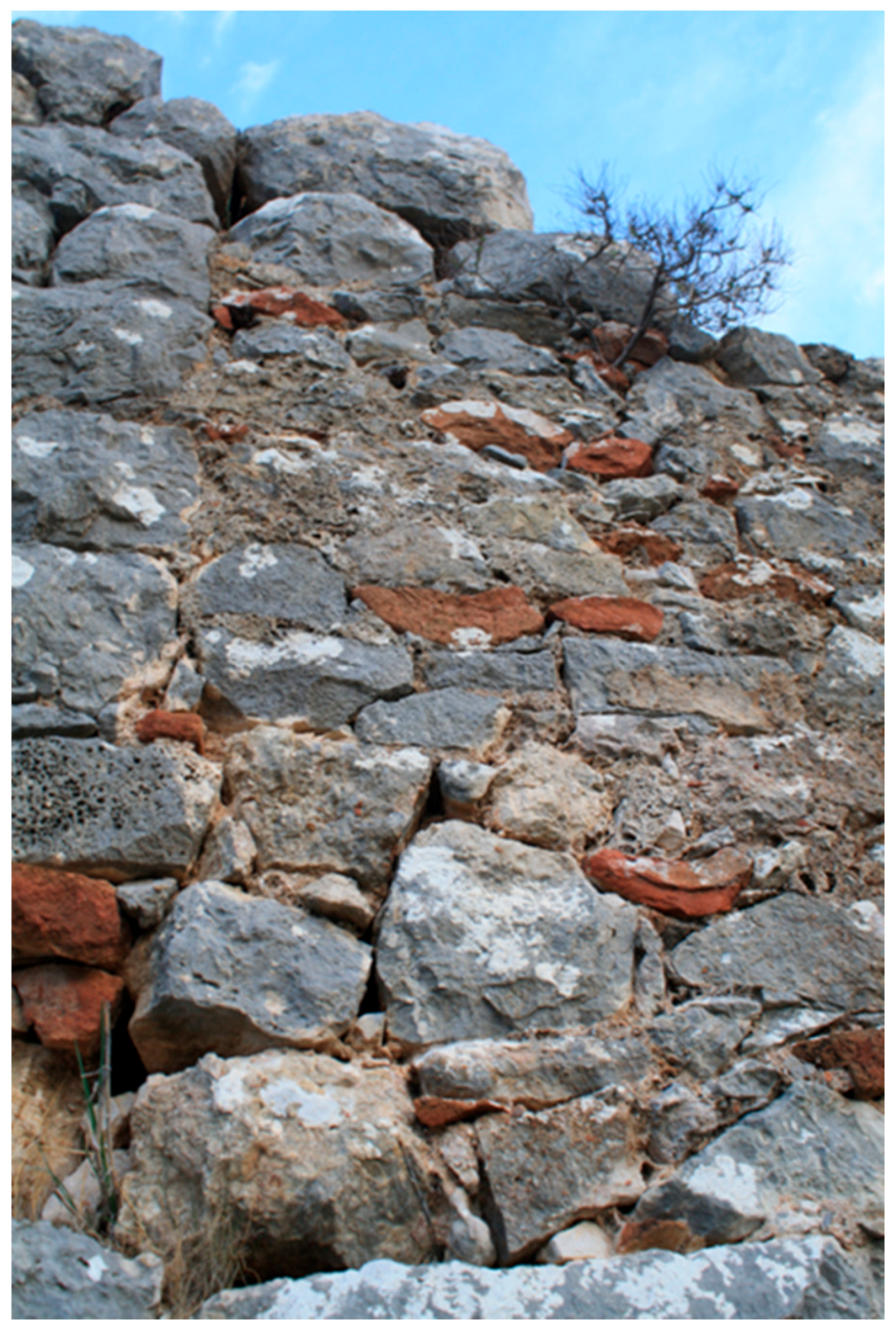
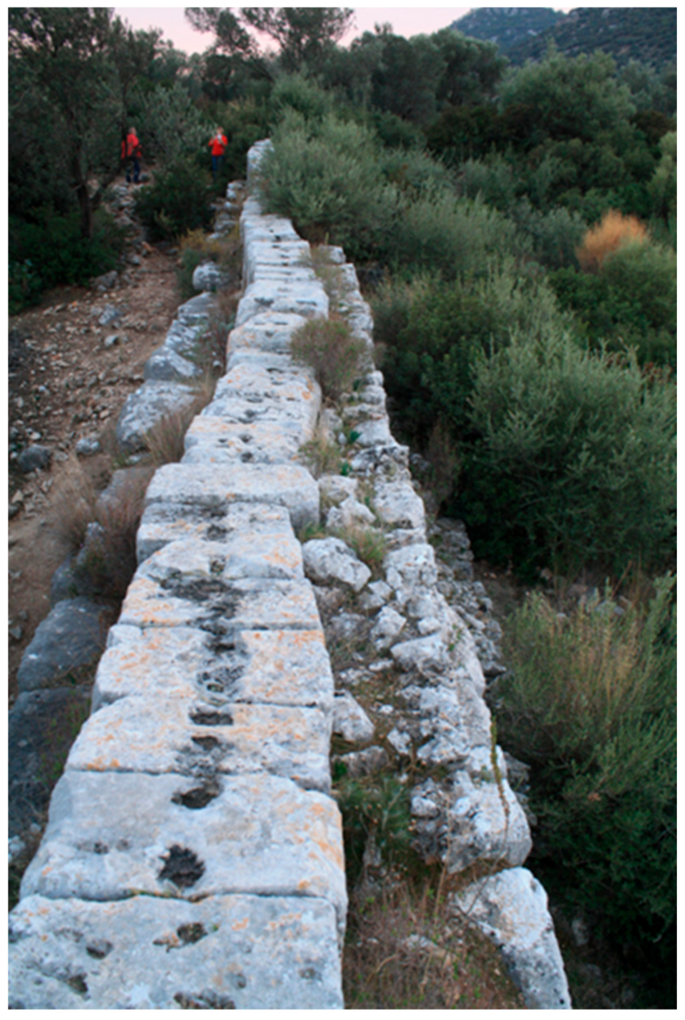
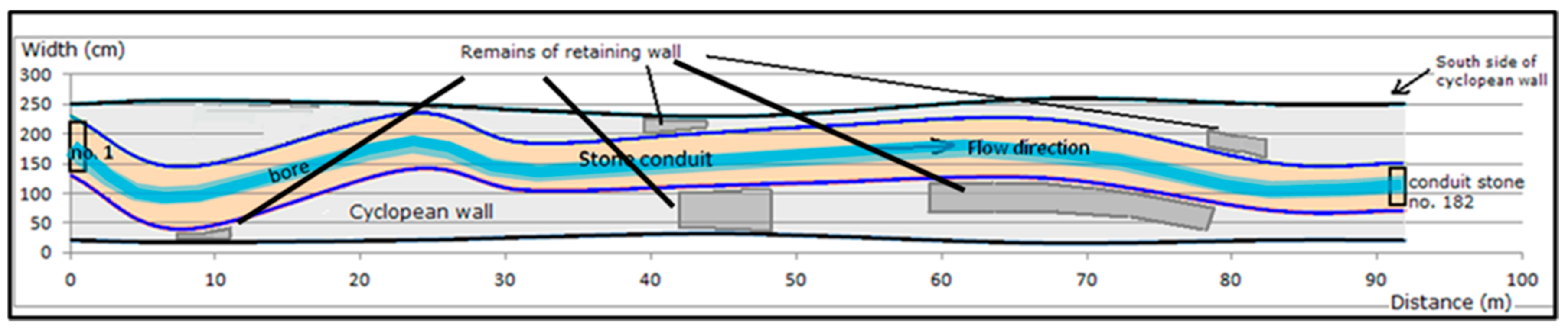
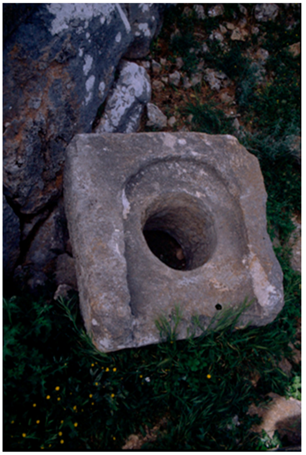
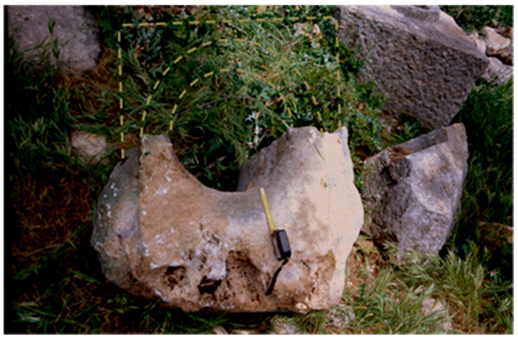
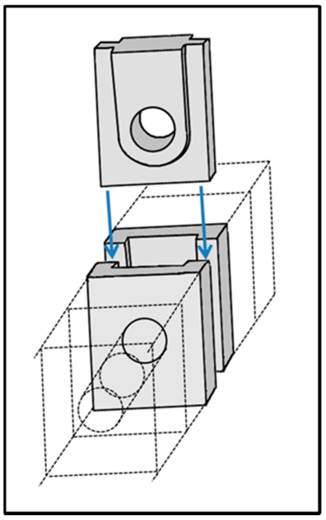
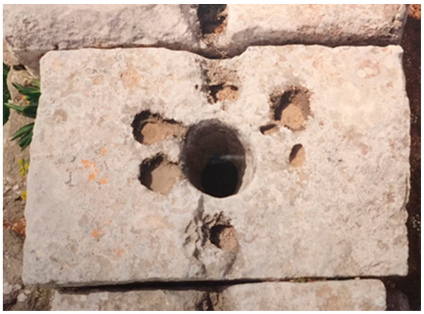
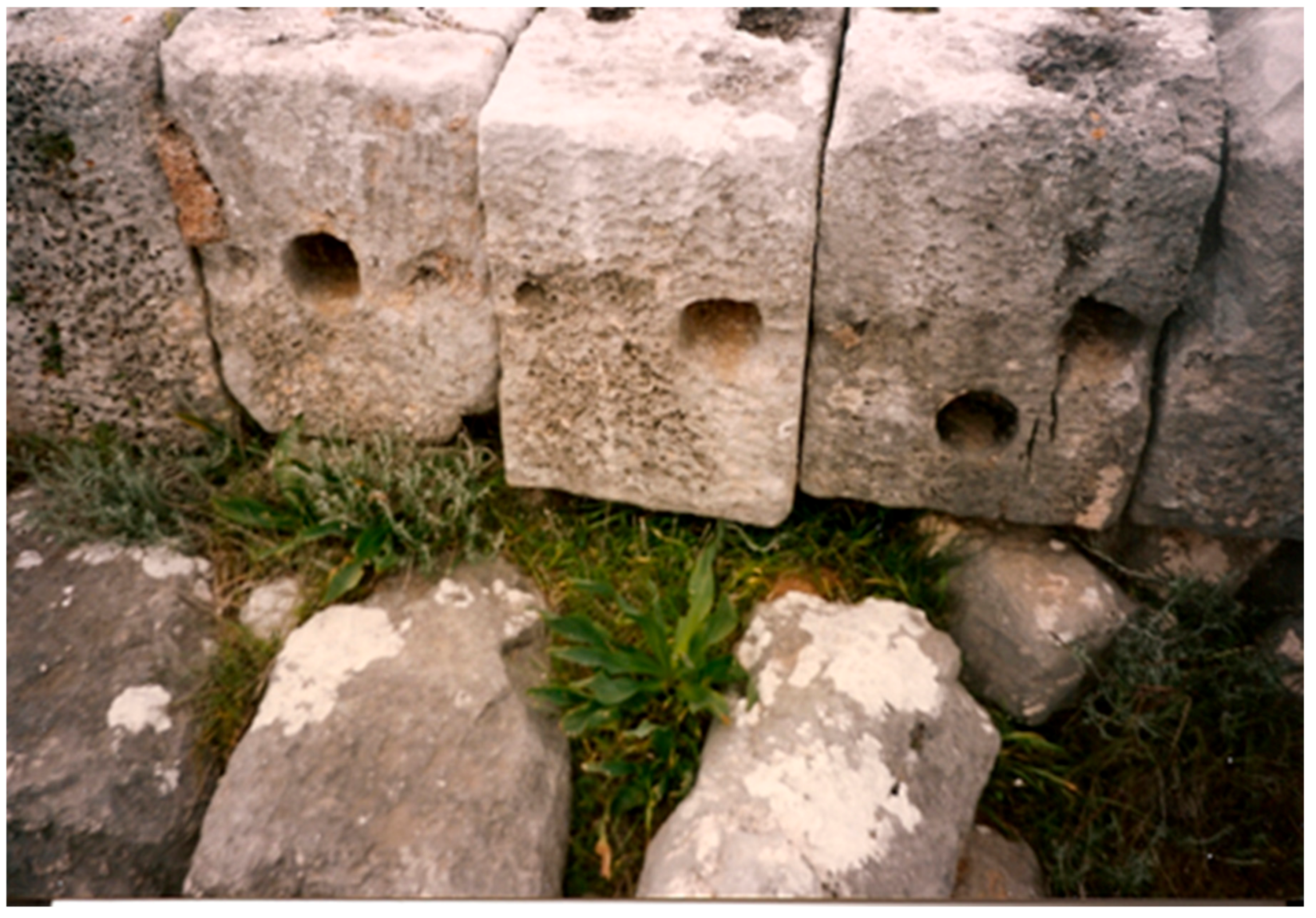
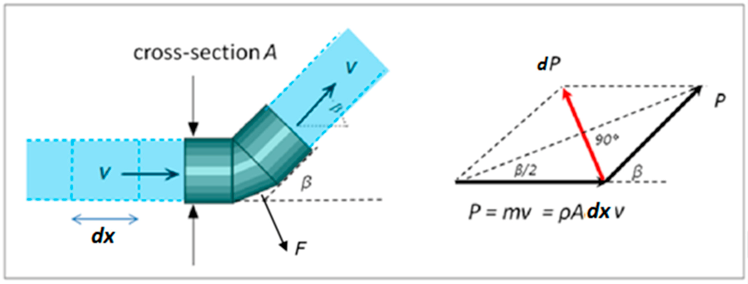
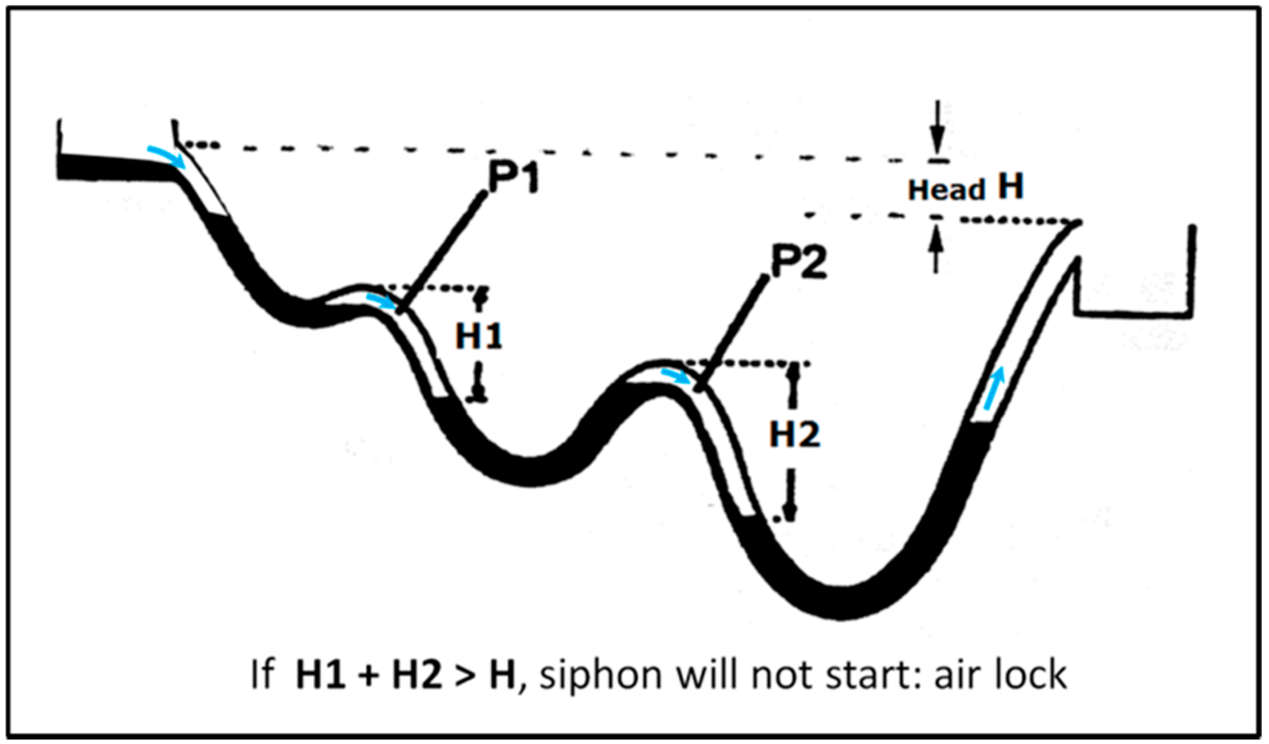
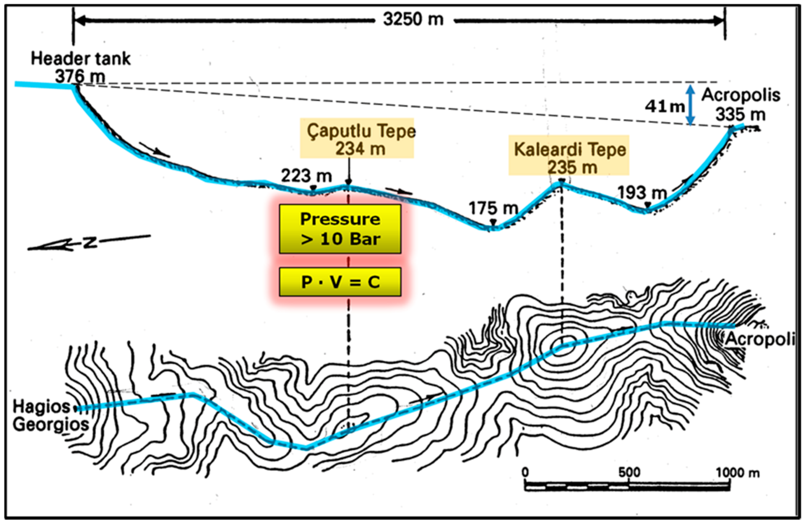
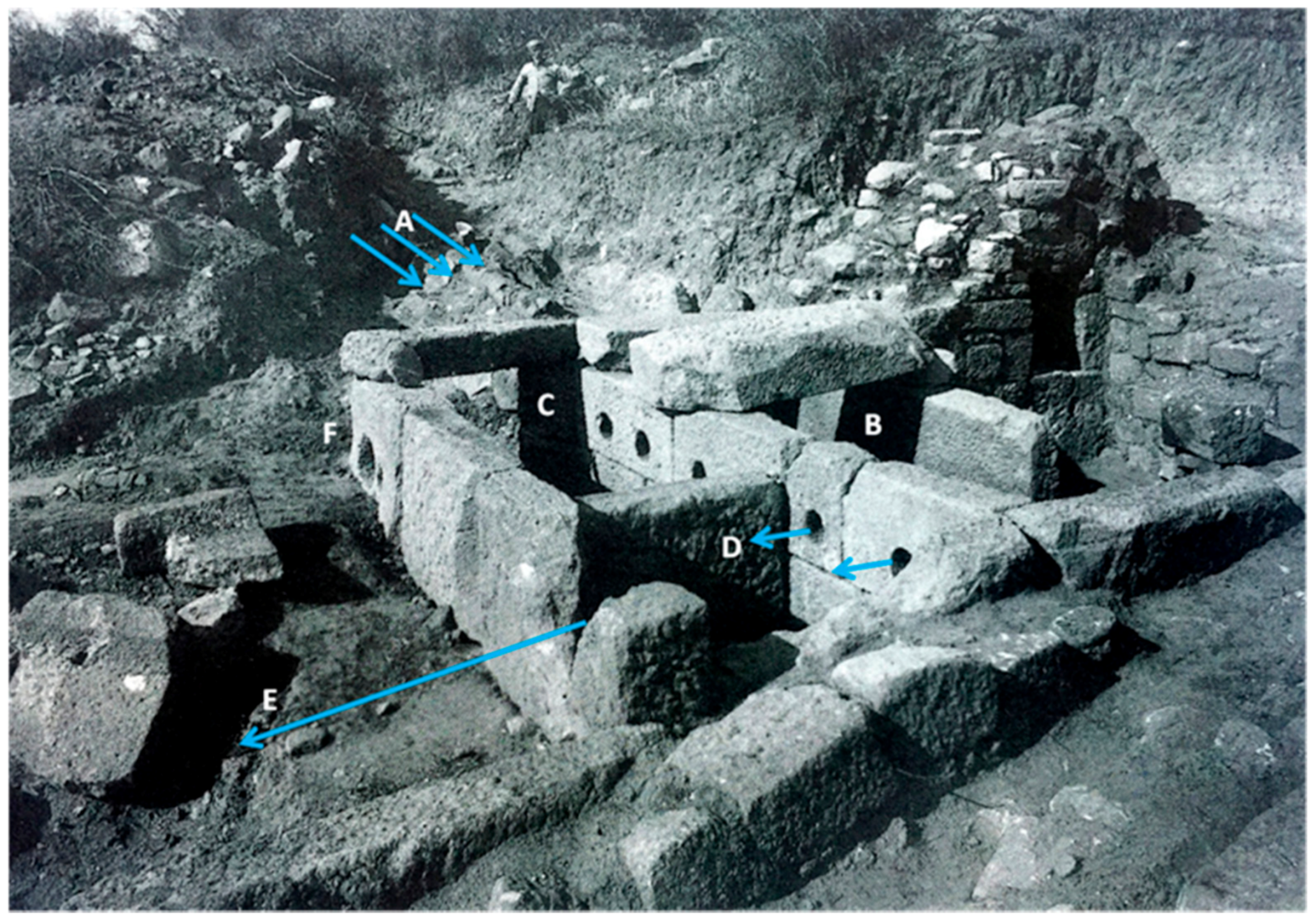
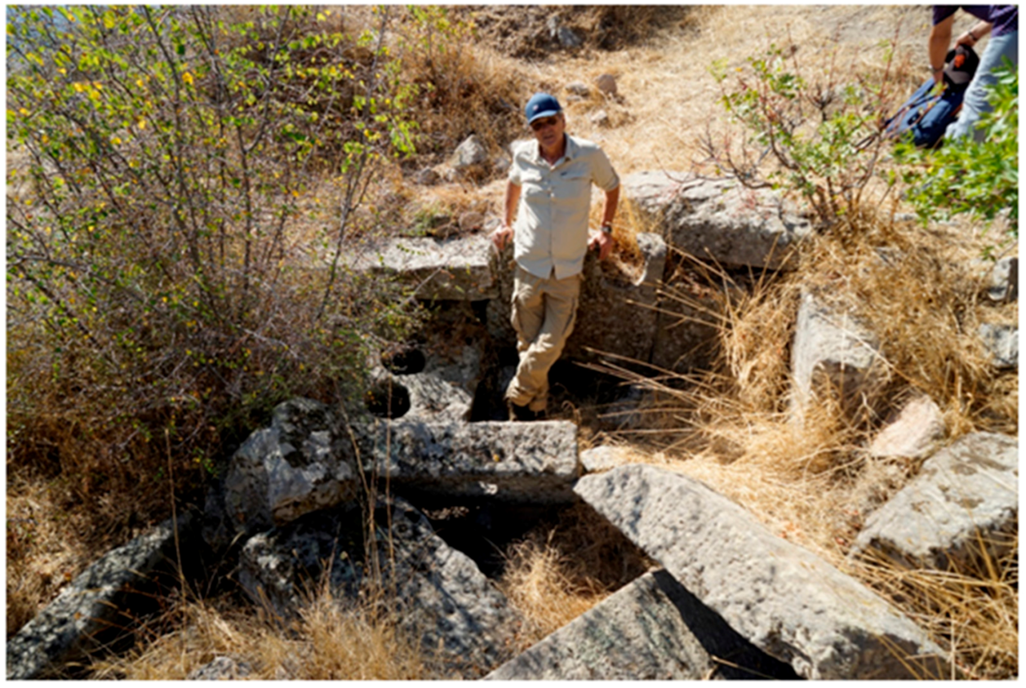
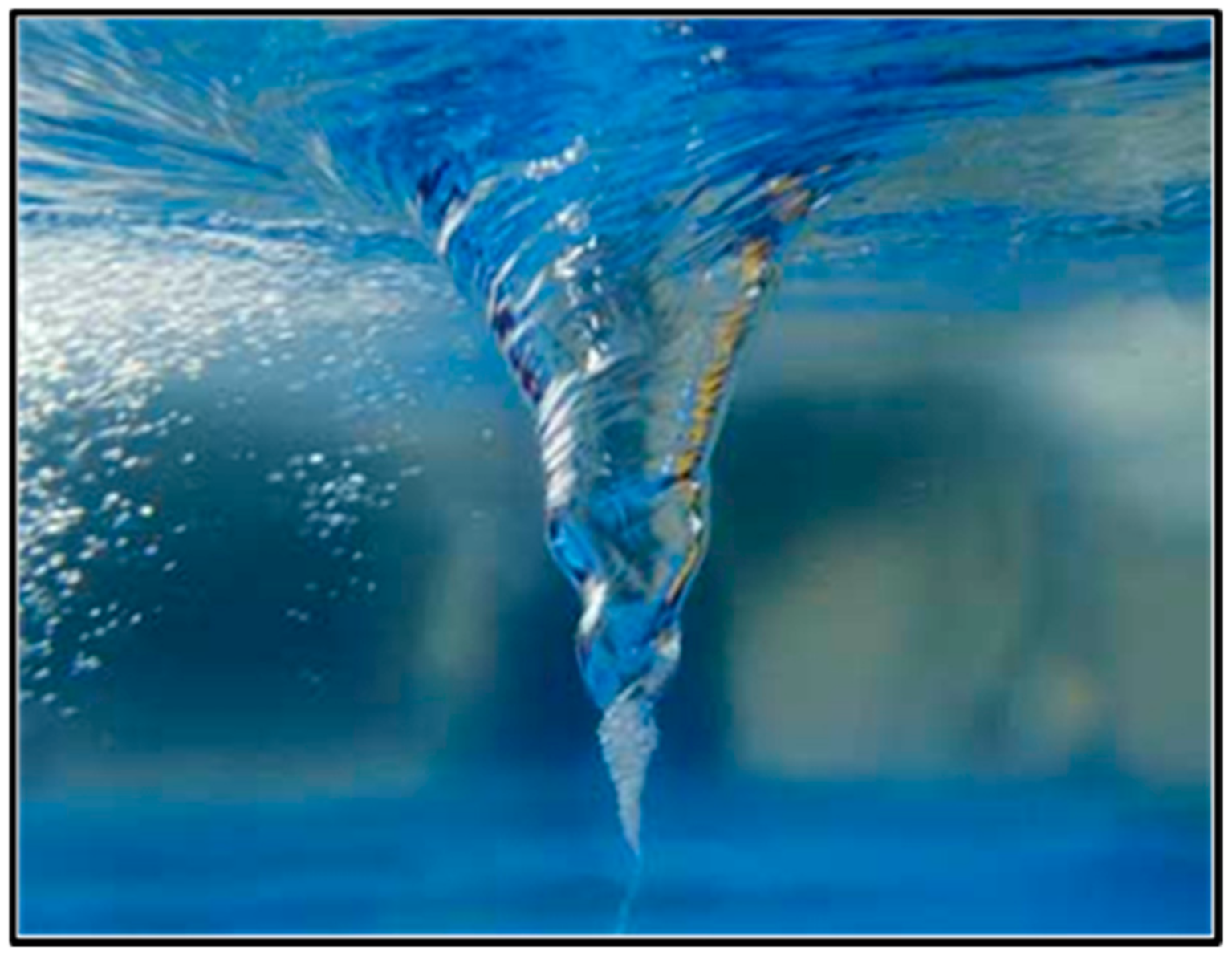
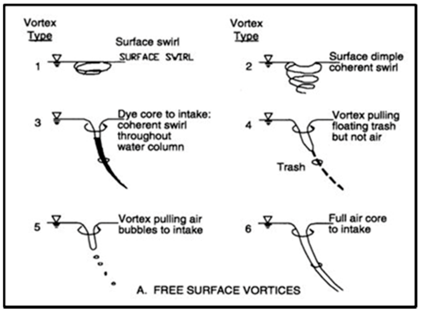
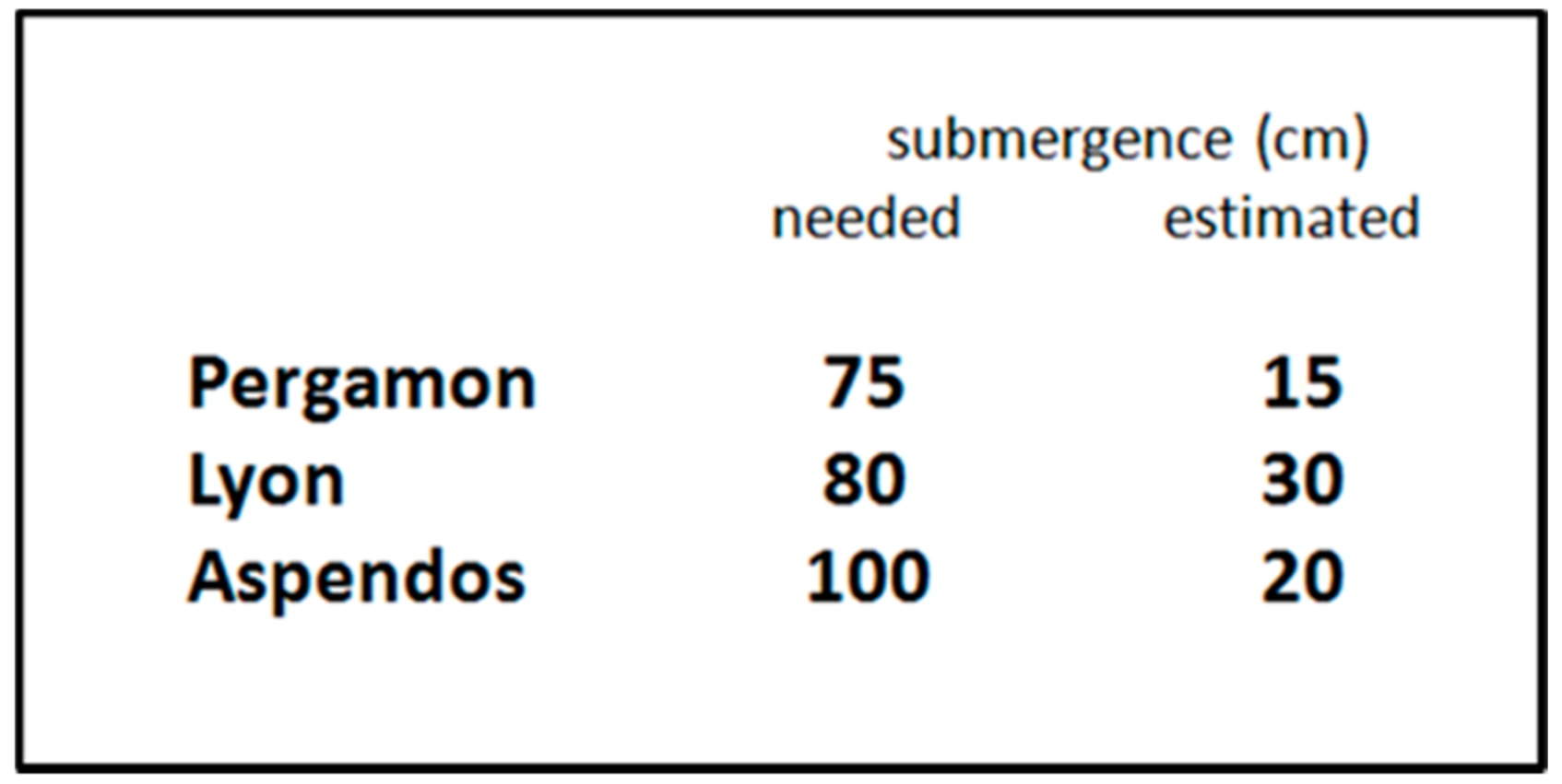
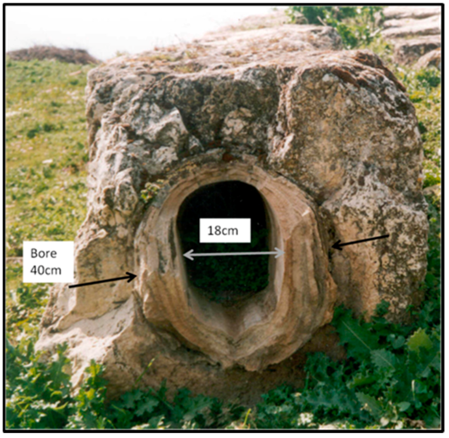
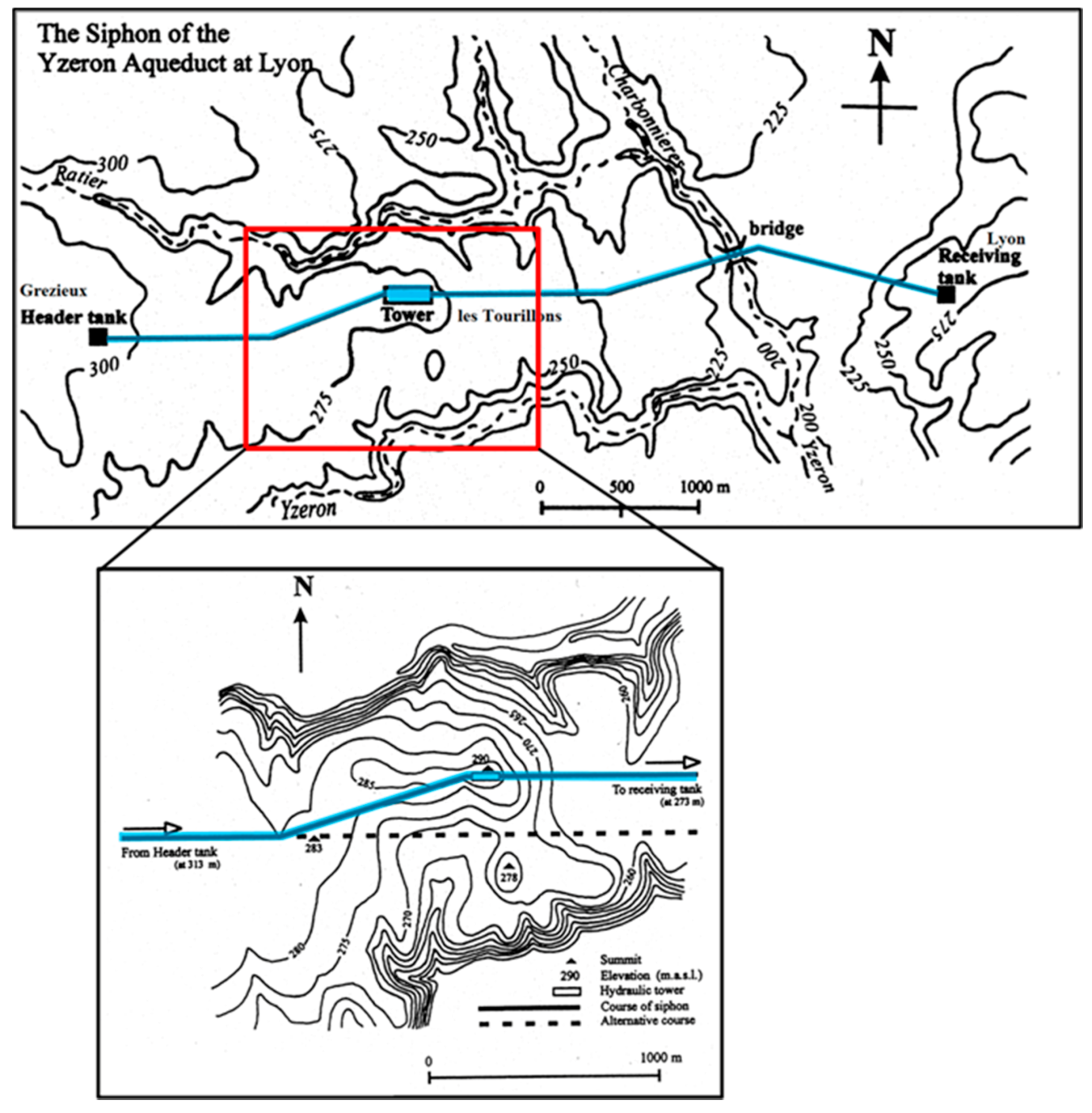
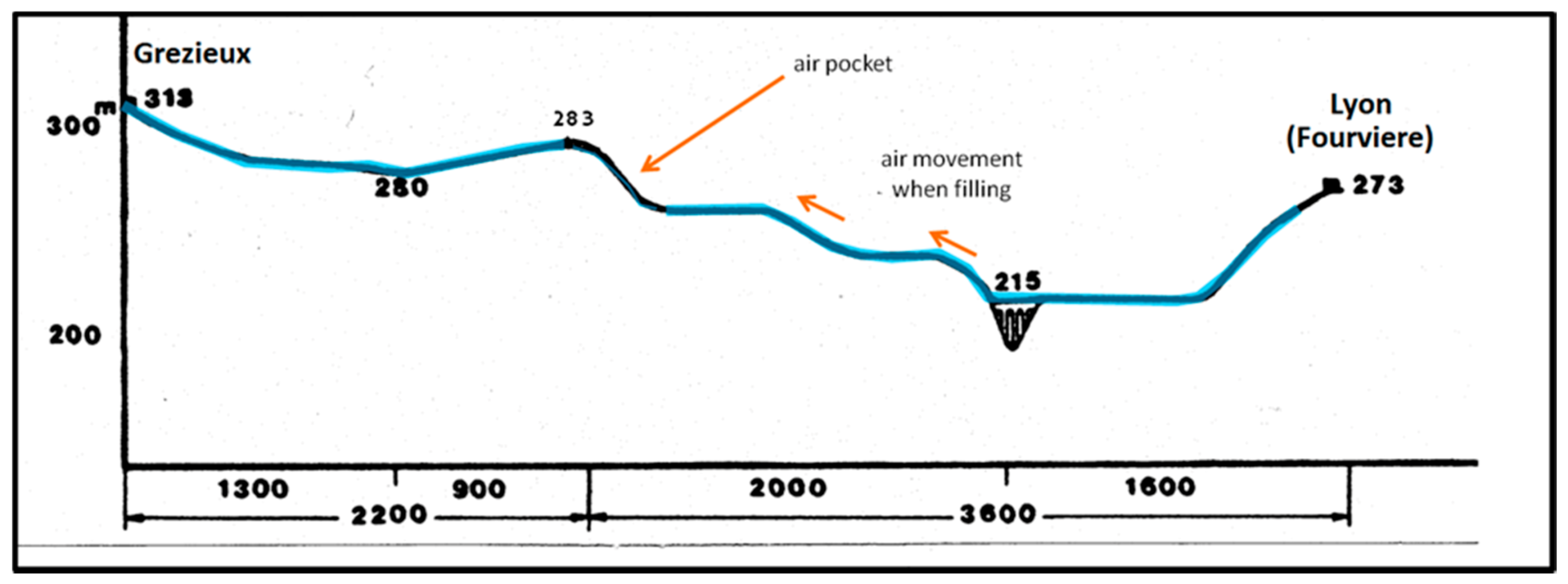
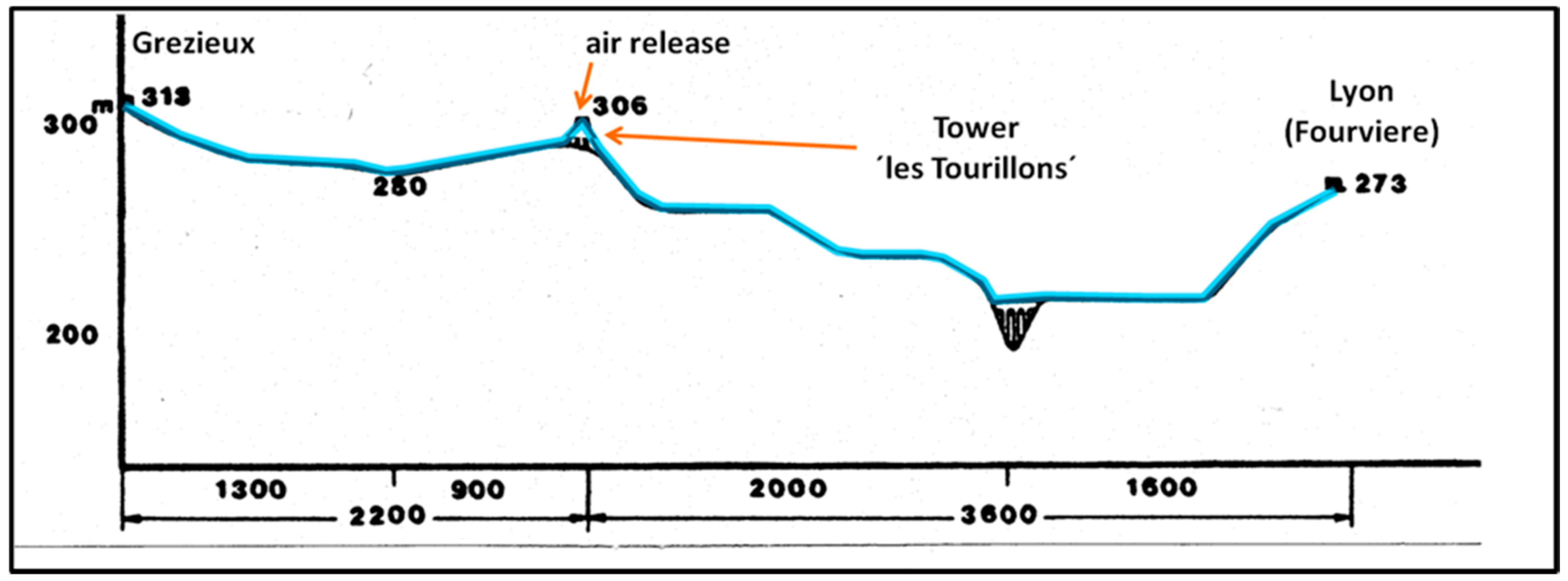
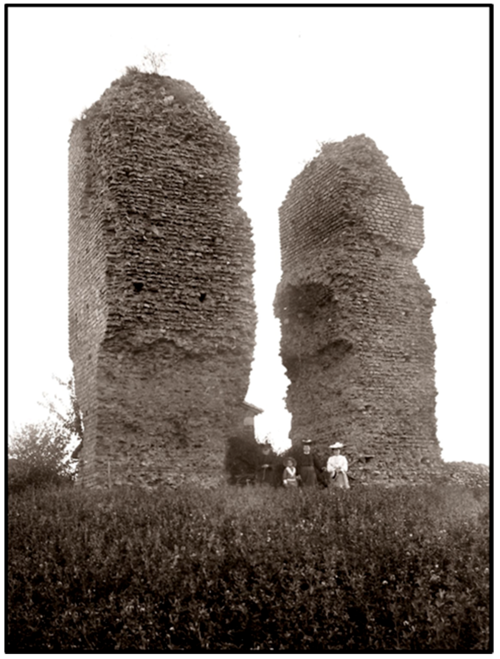
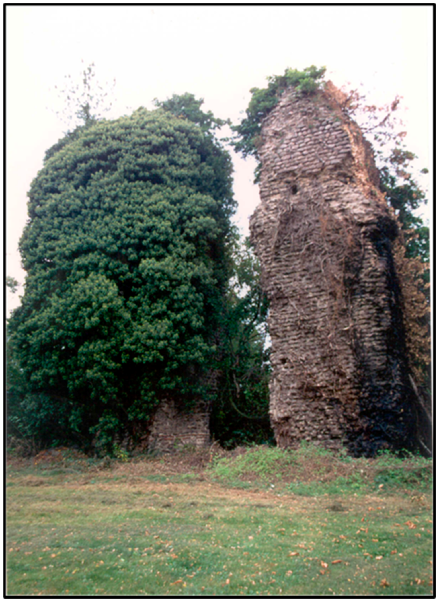
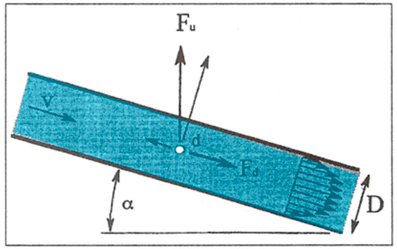
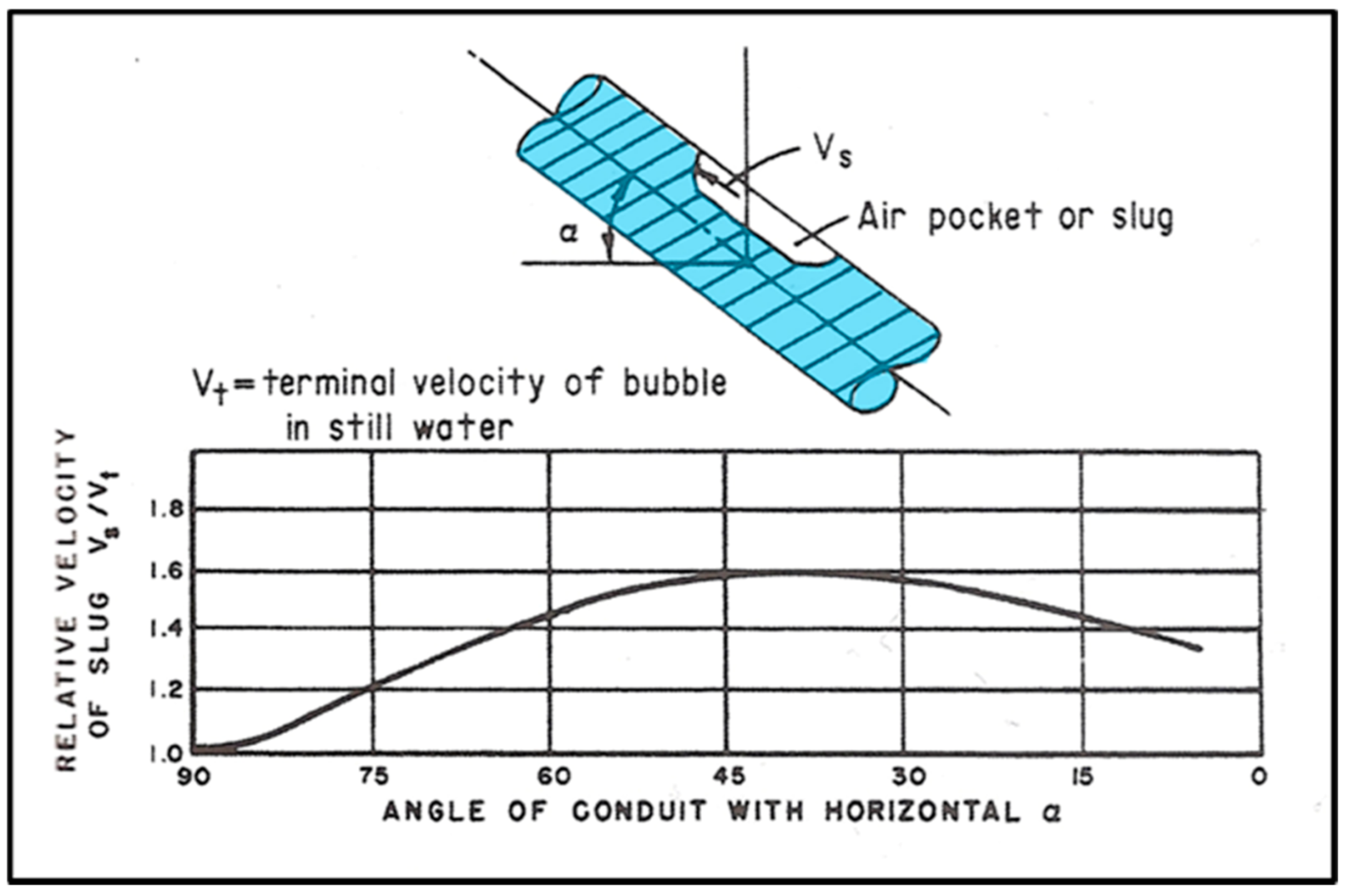
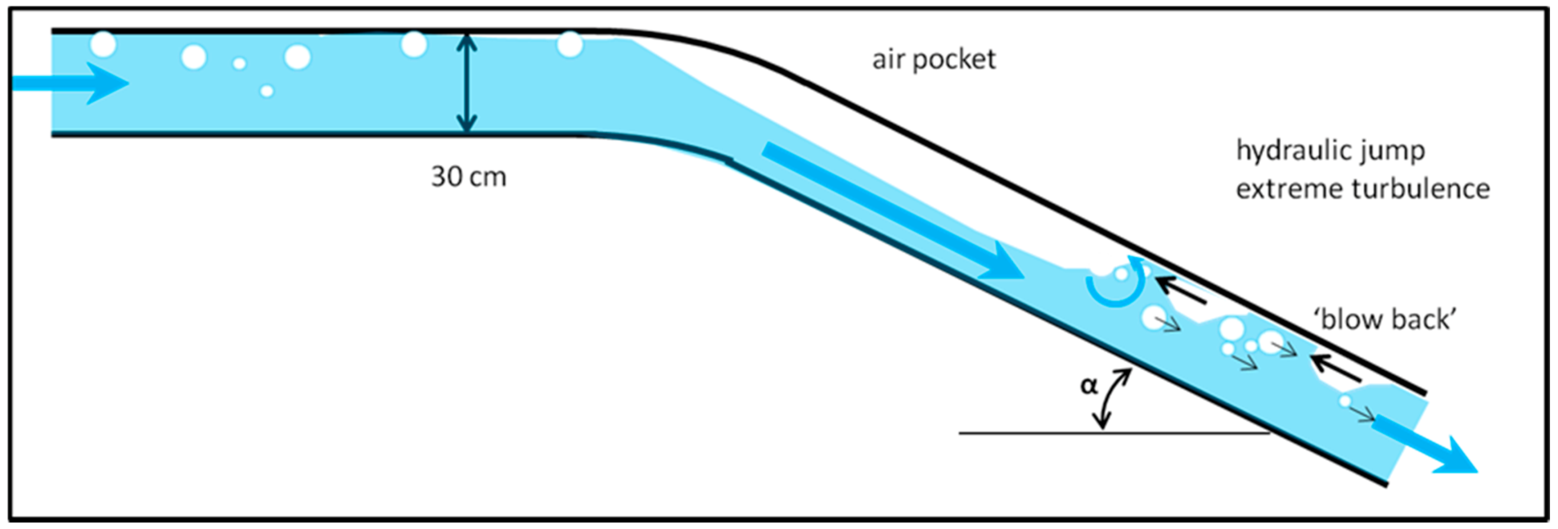
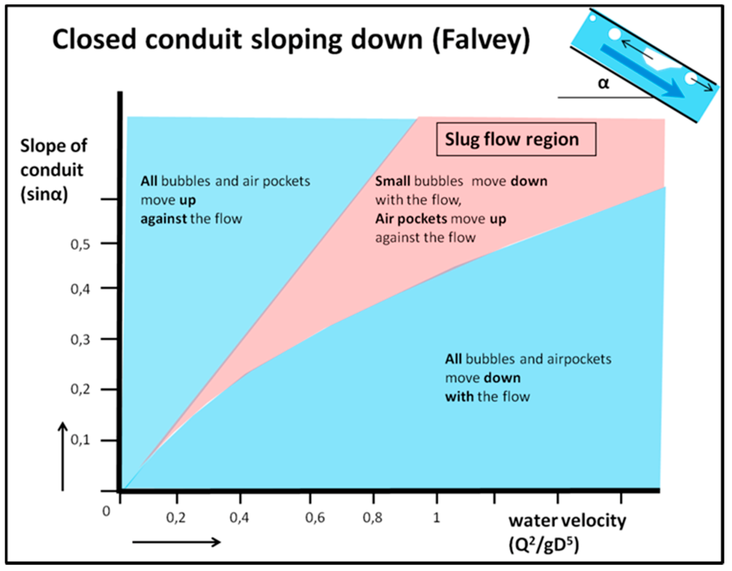
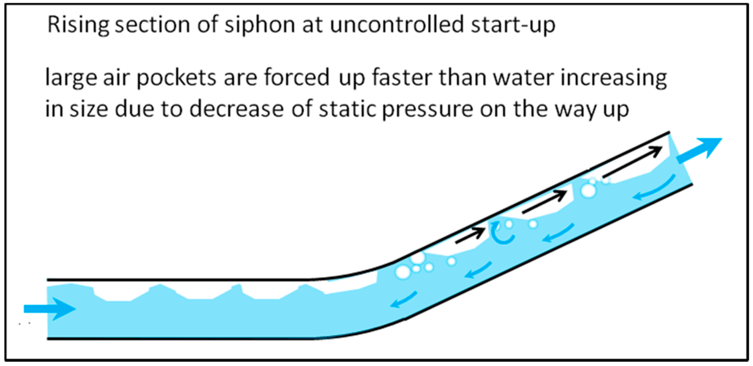
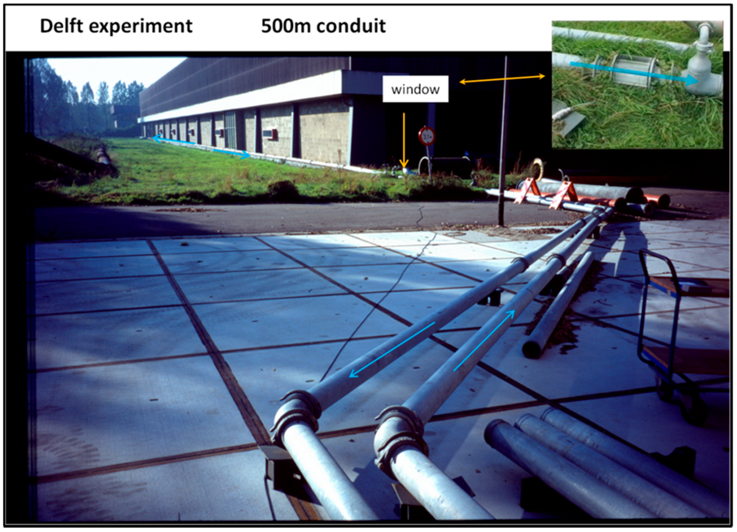
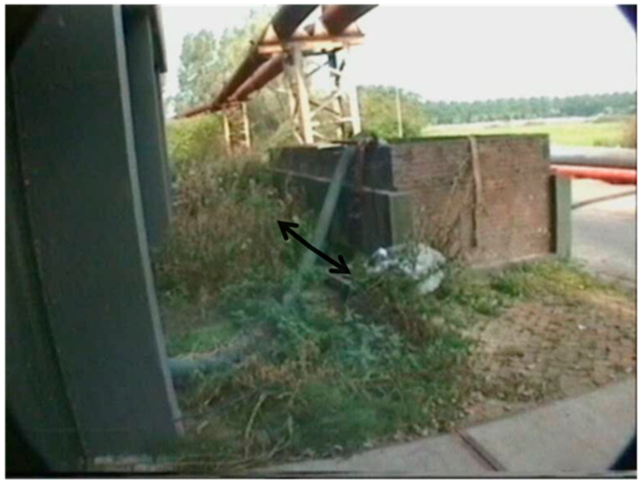
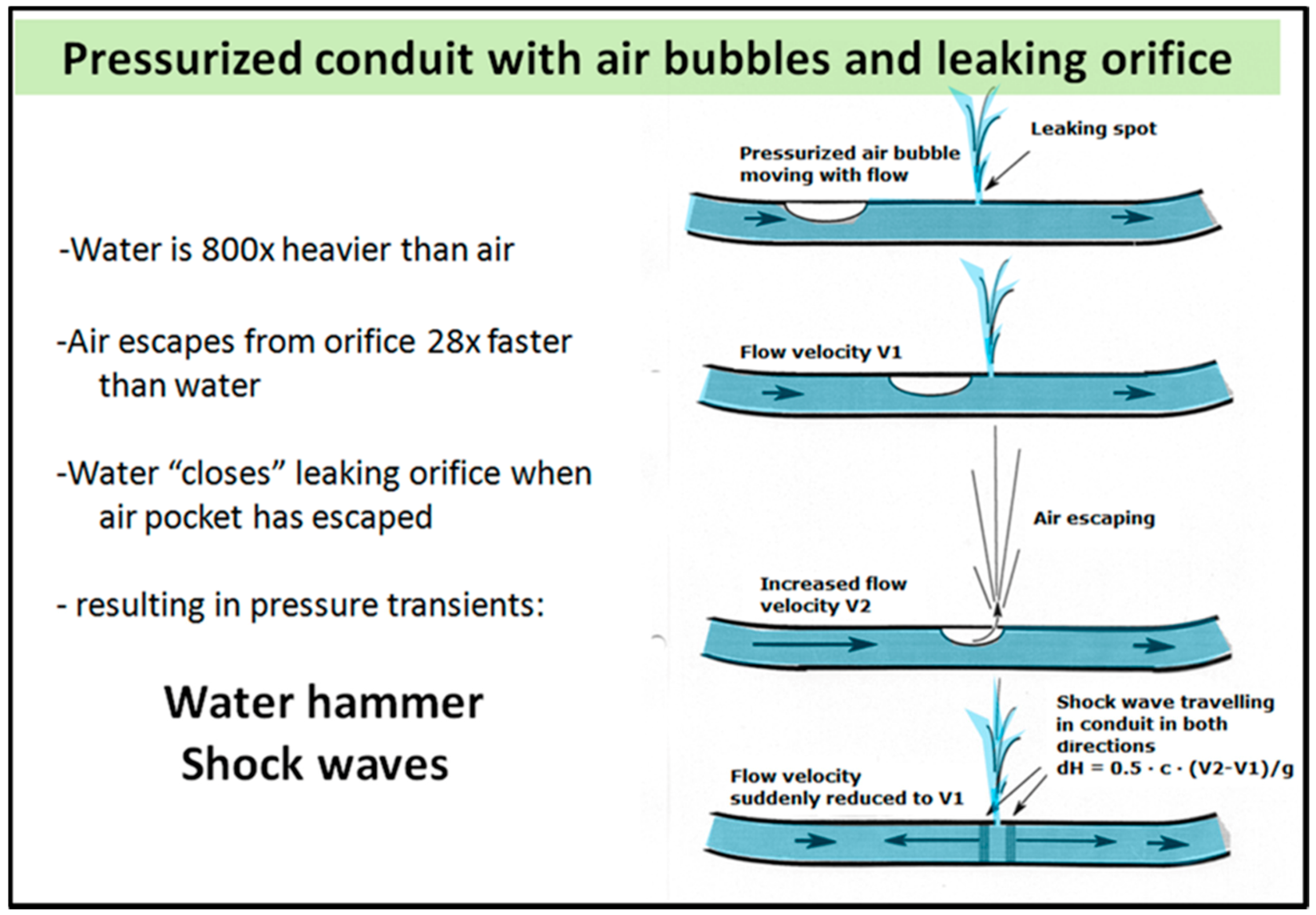
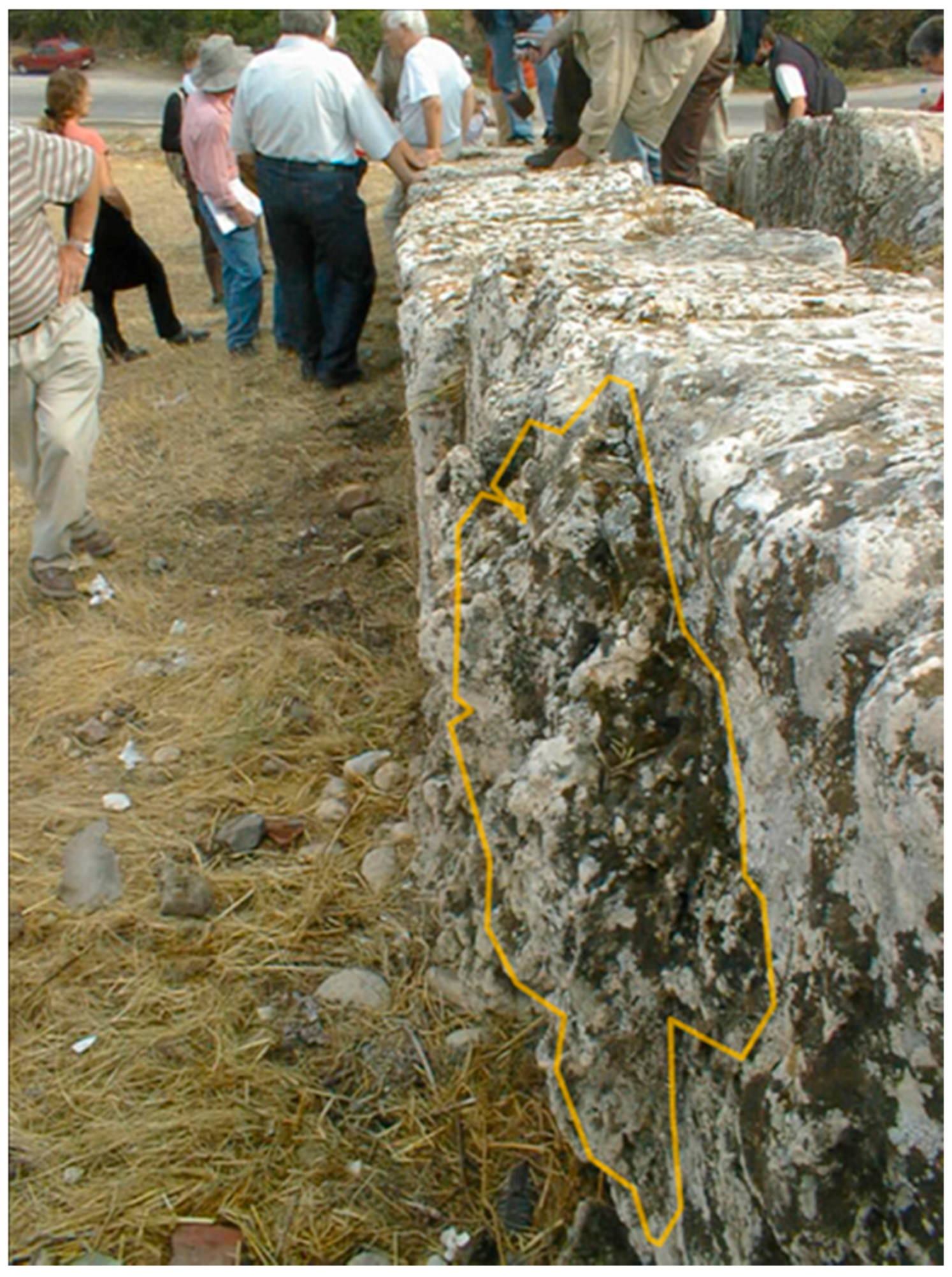
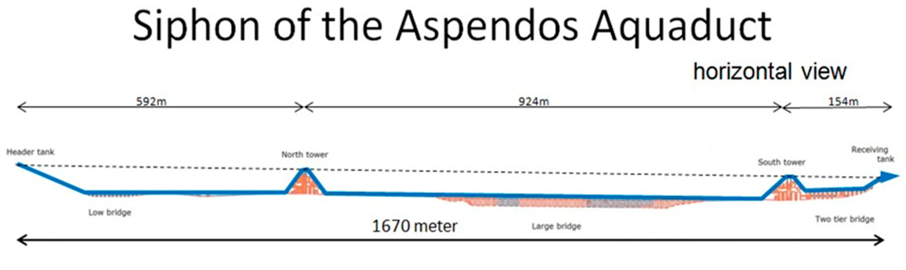
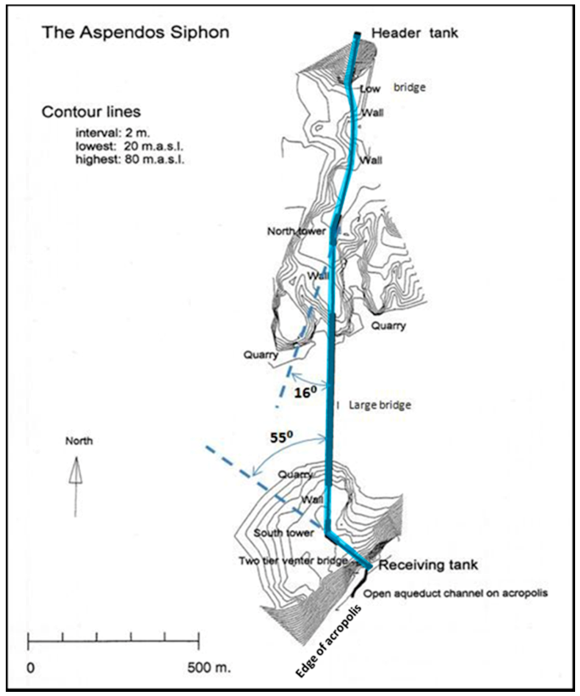
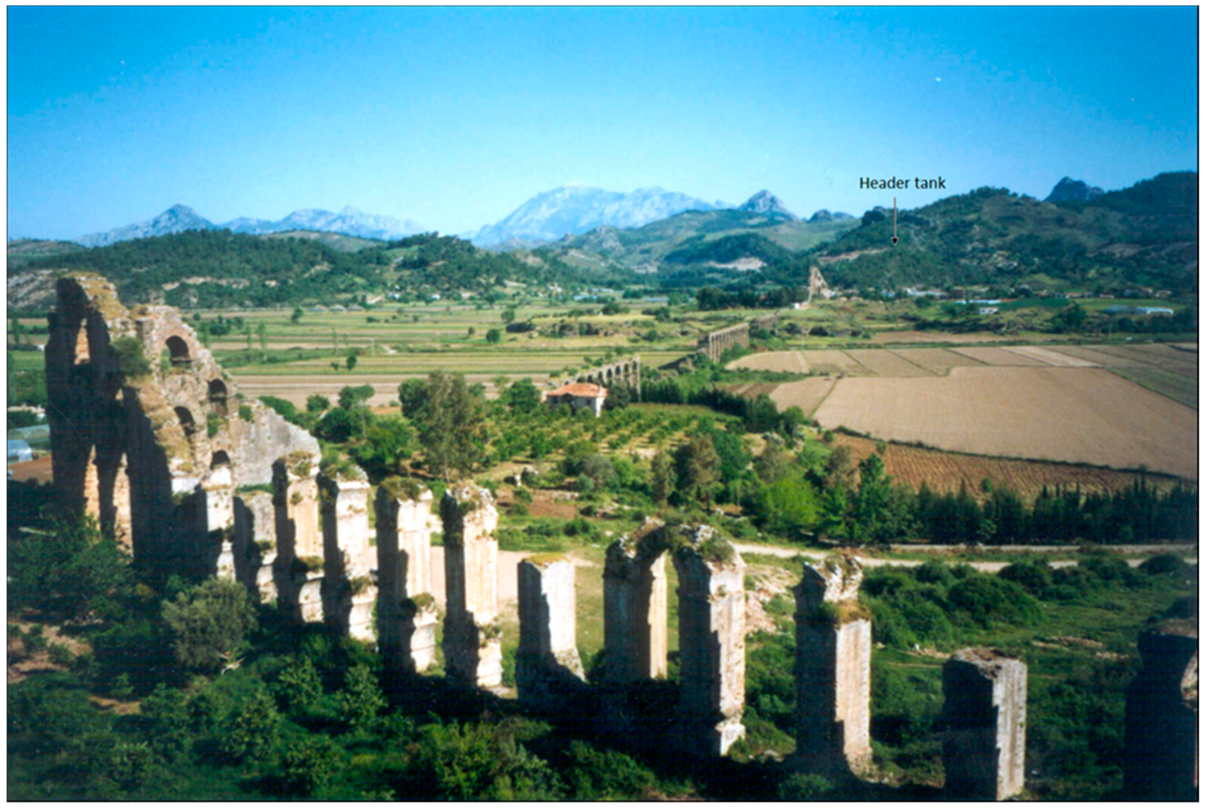
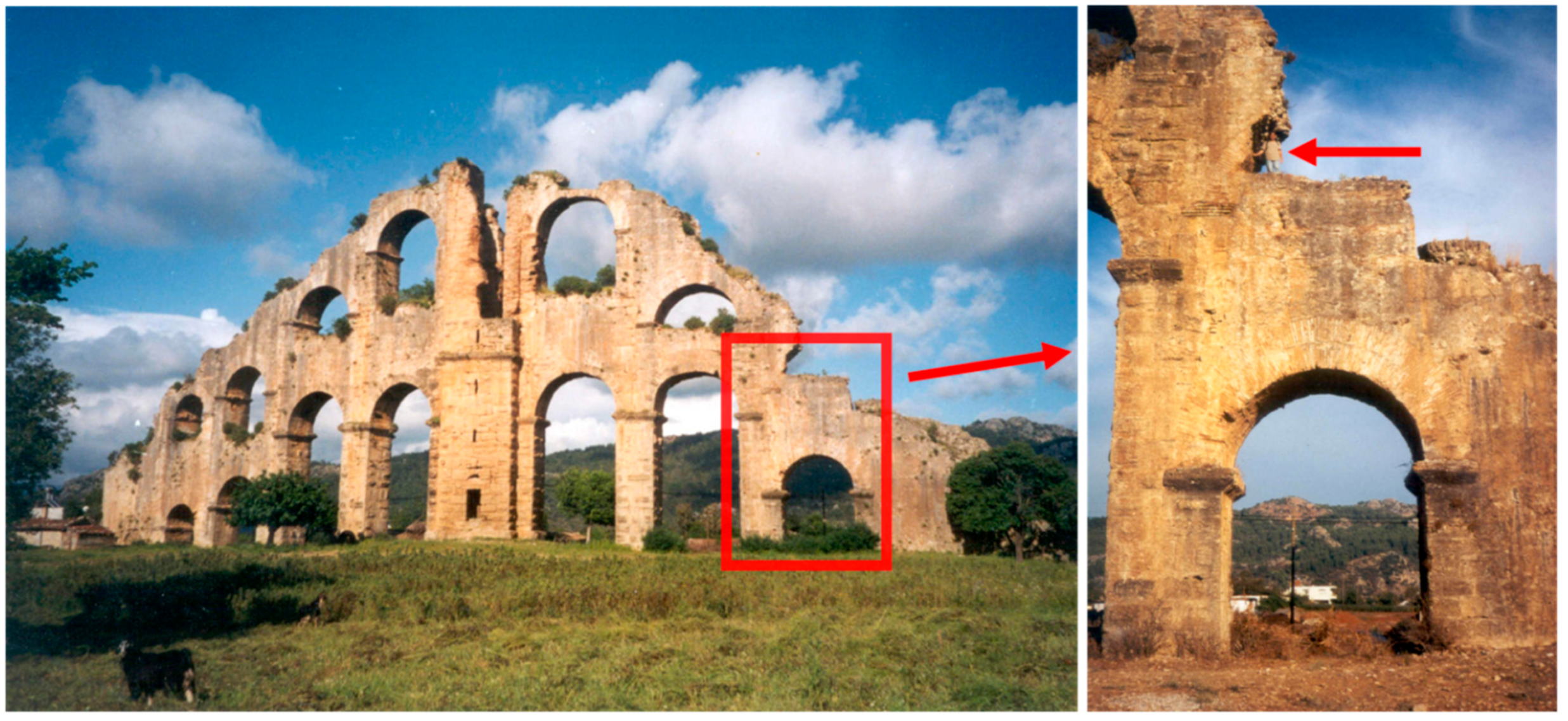
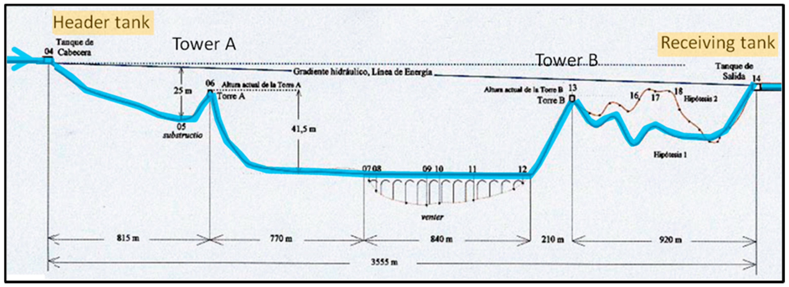
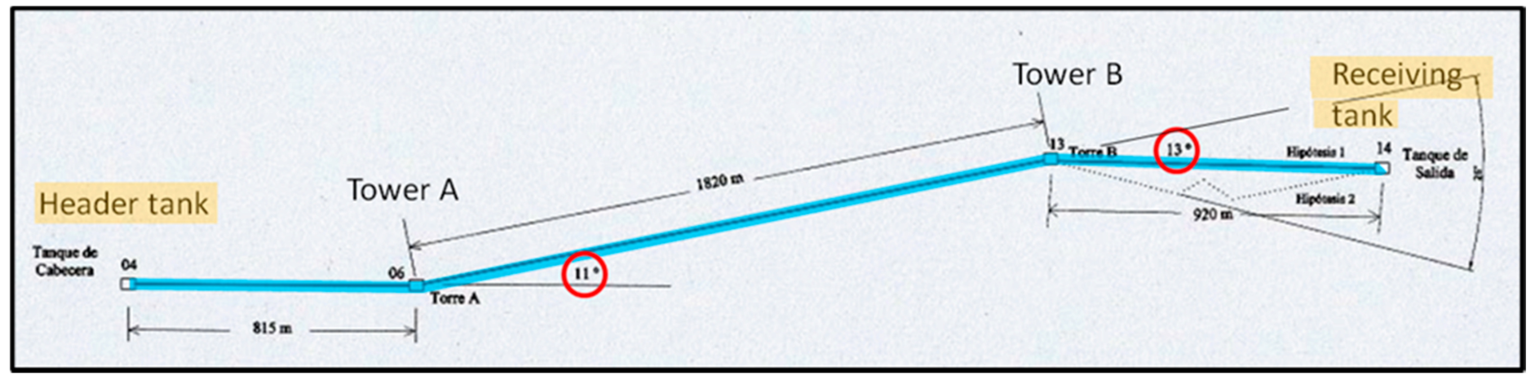
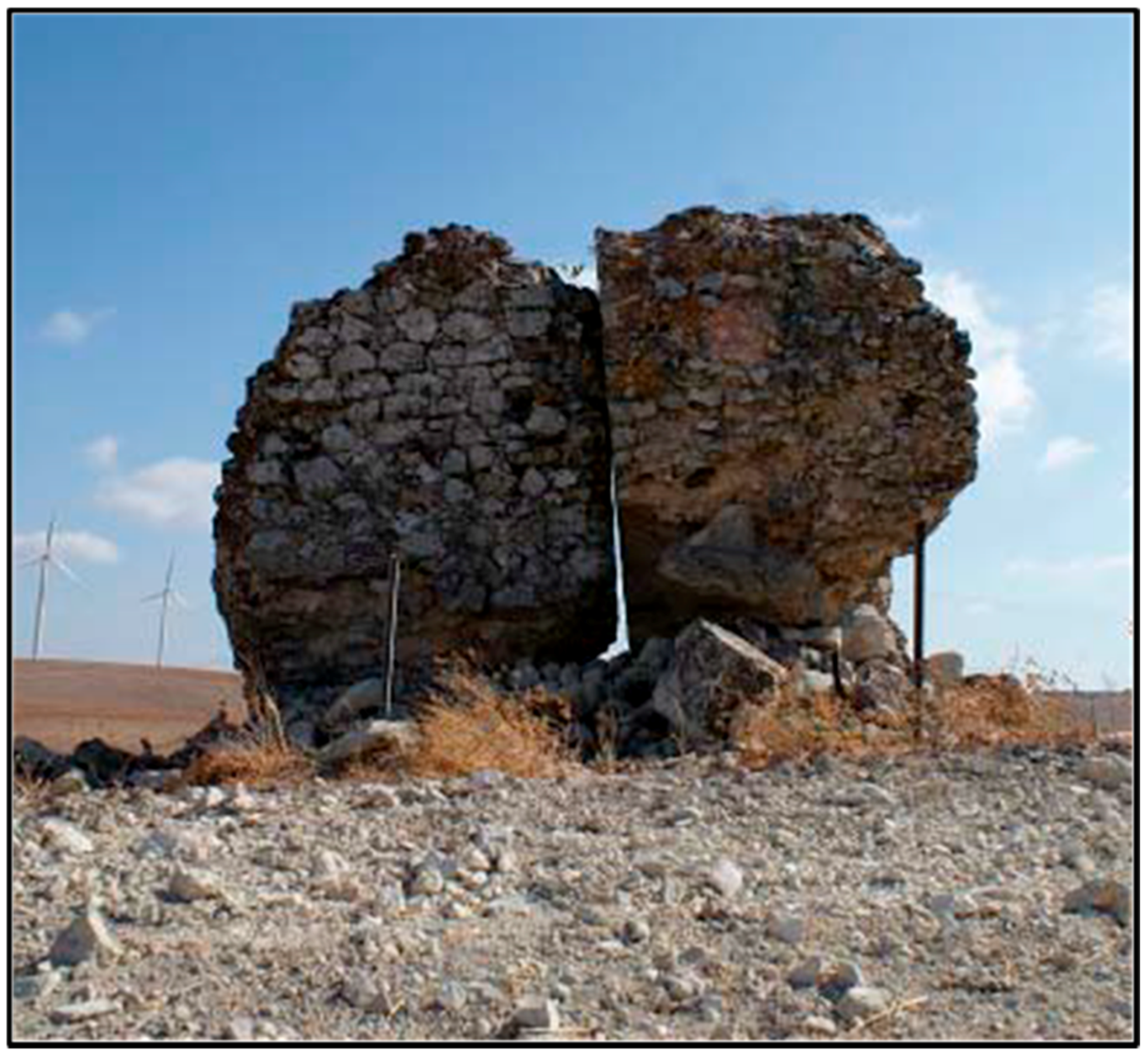
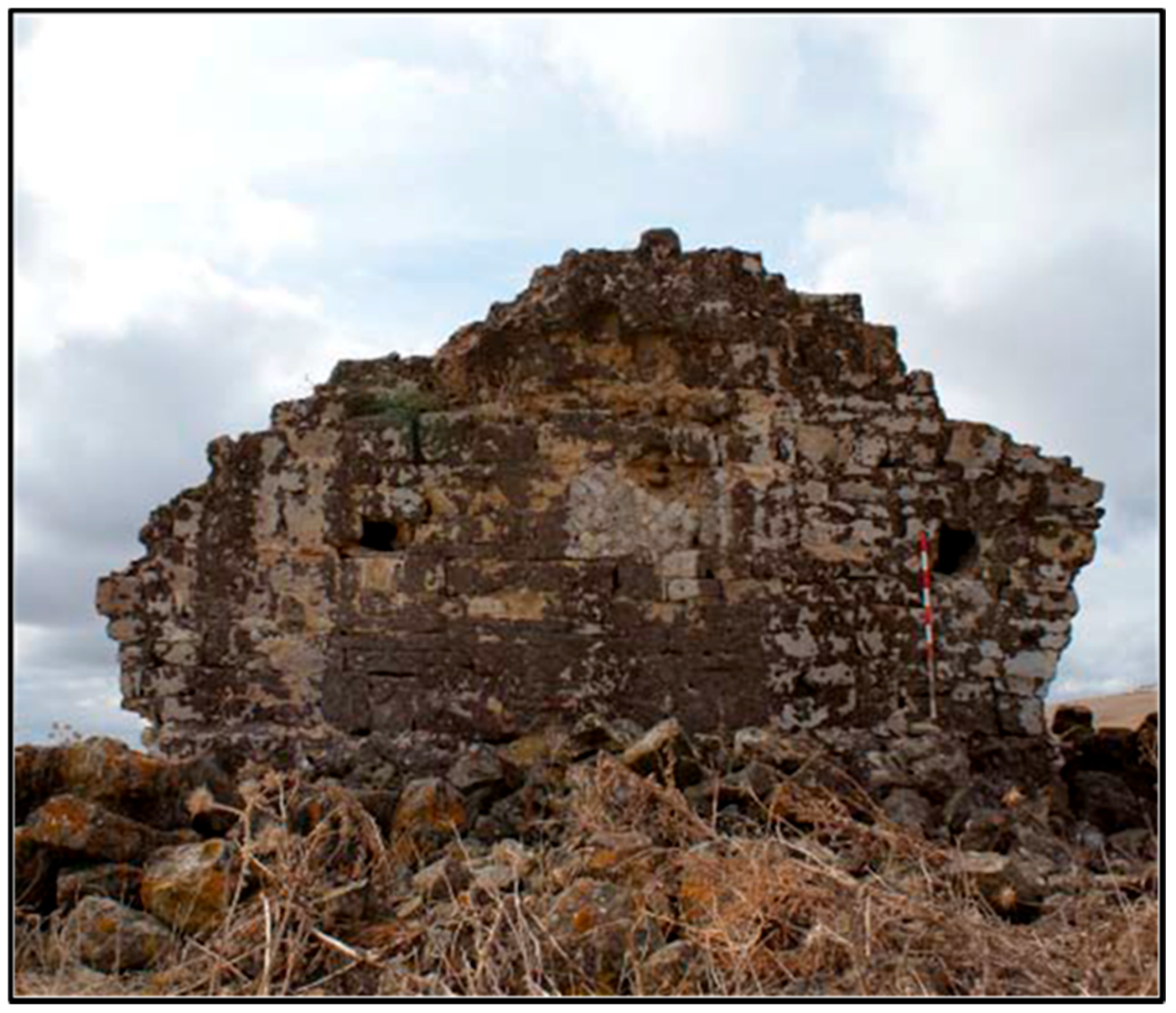
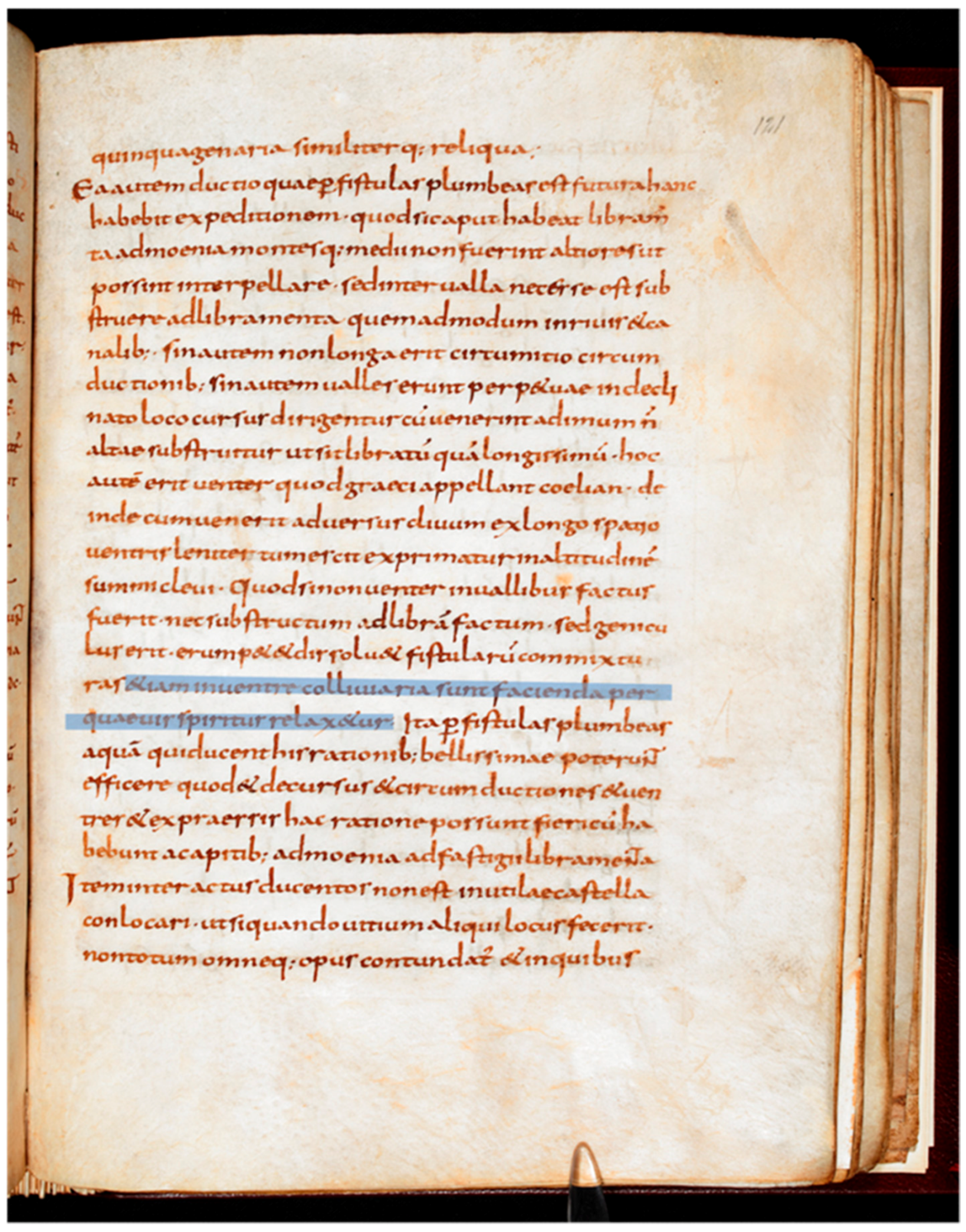
Table 1.
Length of some classical aqueducts. Constantinople: Çeçen 1996; Crow 2012; Sürmelihindi et al. 2021. Carthago: Rakob 1983. Cologne: Haberey 1972; Grewe 1986. Rome: van Deman 1934; Ashby 1935; Blackman 1978; Hodge 1992. Cadiz: Casado 1985, 319; Pérez et al. 2014. Lyon: Burdy 2002. Pergamon: Garbrecht 1978, 1987, 2001. Nîmes: Fabre et al. 2000. Arles: Leveau 1996. Cherchel: Leveau and Paillet 1976. Alcanadre: Mezquiriz 1979. Noviomagus: Kessener 2017a.
| Location | Country | Length (km) |
|---|---|---|
| Constantinople | Turkey | >250 |
| Carthage | Tunesia | 95 |
| Cologne | Germany | 95 |
| Rome (Aqua Marcia) | Italy | 91 |
| Rome (Anio Novus) | Italy | 87 |
| Cadiz (Tempul) | Spain | 83 |
| Lyon (Gier) | France | 75 |
| Rome (Aqua Claudia) | Italy | 69 |
| Lyon (Brevenne) | France | 66 |
| Rome (Anio Vetus) | Italy | 64 |
| Romen (Aqua Traiana) | Italy | 58 |
| Pergamon (Kaikos) | Turkey | 50 |
| Nîmes | France | 50 |
| Arles | France | 48 |
| Cherchel | Algeria | 45 |
| Alcanadre | Spain | 30 |
| Noviomagus | Netherlands | 5 |
Table 2.
Dimensions of some aqueduct channels.
| Aqueduct | City/Country | Inside Channel Dimension (Height × Width, cm) |
|---|---|---|
| Degirmendere | Ephesos/Turkey | 245 × 80 |
| Aqua Marcia | Rome | 240 × 90 |
| Carthago | Tunesia | 190 × 85 |
| Brevenne | Lyon/France | 166 × 120 |
| Cologne | Germany | 142 × 70 |
| Aspendos | Turkey, south coast | 90 × 50 |
| Mont d’Or | Lyon/France | 74 × 44 |
| Patara | Turkey, south coast | 35 × 40 |
Table 3.
Leveling error C due to the curvature of the earth. The error increases rapidly with the distance between A and B. Back-sighting from B to A will result in a similar error at A. Correcting for this error at B gives the horizontal at that point. One may then lower the level at B for the required slope of the channel.
| Distance | Error |
|---|---|
| 100 m | 1 mm |
| 500 m | 2 cm |
| 1 km | 8 cm |
| 5 km | 2 m |
| 10 km | 7.8 m |
| 100 km | 784 m |
| 250 km | 4.9 km |
Table 4.
Length, maximum depth, and hydraulic gradient of some classical siphons.
| City | Aqueduct | Siphon | Material of Conduit | Length (m) | Max Depth (m) | Hydraulic Gradient (m/km) |
|---|---|---|---|---|---|---|
| Gades (Spain) | Tempul | de la Playa | stone | 19,500 | 20 | not known |
| Smyrna (Turkey) | Kara-Bunar | Kara-Bunar | clay/stone | 4400 | 158 | 1.1 (estimate) |
| Lyon (France) | Yzeron | Craponne-Lyon | lead | 3600 | 91 | 9.2 |
| Gades | Tempul | de los Arquilles | stone | 3555 | 50 | 3.1 |
| Lyon | Mont d’Or | d’Ecully | lead | 3500 | 70 | 3.1 |
| Lyon | Brevenn | Grange-Blanche | lead | 3500 | 90 | 4–5.6 (estimate) |
| Pergamon (Turkey) | Madradag | Madradag | lead | 3250 | 190 | 12.6 |
| Alatri (Italy) | Alatri | Alatri | lead | 3000 | 100 | 9 (estimate) |
| Lyon | Gier | Beaunant | lead | 2660 | 122 | 3.0 |
| Lyon | Yzeron | Grezieux-Craponne | lead | 2200 | 33 | 3.2 |
| Aspendos (Turkey) | Aspendos | Aspendos | stone | 1670 | 45 | 8.3 |
| Termini Imerese (Sicily) | Cornelio | Barratina | lead | 1300 | 40 | 3.8 |
| Lyon | Gier | Soucieu (le Garon) | lead | 1210 | 93.5 | not known |
| Laodikeia ad Lykum (Turkey) | Laodikeia | Laodikeia | stone | 800 | 50 | 26 |
| Lyon | Gier | St. Genis | lead | 700 | 79 | 8.3 |
| Lyon | Gier | St. Irenée | lead | 575 | 38 | 4 |
| Oinoanda (Turkey) | Oinoanda | Oinoanda | stone | 500–700 | 22 | 6–16 (estimate) |
| Lyon | Mont d’Or | Cotte-Chally | lead | 420 | 30 | 19 |
| Patara (Turkey) | Patara | Delik Kemer | stone | 260 | 20 | 18.5 |
Publisher’s Note: MDPI stays neutral with regard to jurisdictional claims in published maps and institutional affiliations. |
© 2021 by the author. Licensee MDPI, Basel, Switzerland. This article is an open access article distributed under the terms and conditions of the Creative Commons Attribution (CC BY) license (https://creativecommons.org/licenses/by/4.0/).
Share and Cite
MDPI and ACS Style
Kessener, P.M. Roman Water Transport: Pressure Lines. Water 2022, 14, 28. https://doi.org/10.3390/w14010028
AMA Style
Kessener PM. Roman Water Transport: Pressure Lines. Water. 2022; 14(1):28. https://doi.org/10.3390/w14010028
Chicago/Turabian StyleKessener, Paul M. 2022. "Roman Water Transport: Pressure Lines" Water 14, no. 1: 28. https://doi.org/10.3390/w14010028
Note that from the first issue of 2016, this journal uses article numbers instead of page numbers. See further details here.