
Effect Analysis of Supporting Structure and Surface Settlement on Deep Foundation Pit by Rainstorm: A Case Study in Zhengzhou

1
College of Geosciences and Engineering, North China University of Water Resources and Electric Power, Zhengzhou 450045, China
2
School of Civil Engineering and Architecture, Zhengzhou University of Aeronautics, Zhengzhou 450000, China
3
Guangzhou Metro Design & Research Institute Co., Ltd., Guangzhou 510000, China
*
Author to whom correspondence should be addressed.
Water 2022, 14(22), 3654; https://doi.org/10.3390/w14223654
Submission received: 8 October 2022
/
Revised: 9 November 2022
/
Accepted: 10 November 2022
/
Published: 13 November 2022
(This article belongs to the Section Water Erosion and Sediment Transport)
Abstract
:Rainfall usually leads to soil slope sliding and instability, which affects the safety of foundation pit, especially in the case of heavy rainfall. This study took the 7.20 Henan rainstorm as the background, where in the process of construction, after three days of rainstorm of 617.7 mm deep, the horizontal displacement of supporting structures of a foundation pit in Zhengzhou city increased by 6.3 mm. Therefore, it is of great significance to study the mechanism of deformation induced by rainstorm of foundation pits. Five numerical models considering different rainfall factors were developed to simulate the rainstorm process based on the monitoring data. The deformation mechanism and the effect factors of deformation on the foundation pit during rainstorm were analyzed, and some preventive measures were put forward for when the foundation pit engineering faces a heavy rainstorm. Under the action of the rainstorm, the supporting structure and the surface settlement had a signification deformation caused by the heavy rainfall on this typical foundation pit, and the maximum bending moment and maximum displacement of the supporting structure shifted up to different degrees. The main factors affecting the deep foundation pit of the metro by heavy rain are the steel strut falling off and the whole foundation pit filling with water, while the influence caused by the rise in the groundwater level, water standing load, and soil softening is small.
1. Introduction
From the opening of the first subway line in China to 31 December 2021, 7209.7 km of metro has been opened in China [1]. The booming development of the urban metro has brought about a multitude of deep foundation pit engineering. In the construction of foundation pit engineering, rainfall has a great effect on the safety of foundation pit engineering. Rainfall will lead to the decrease in the shear strength with a rise in the soil’s moisture content, and the water head difference between the inside and outside of the foundation pit may be increased, which will reduce the security of the foundation pit and put the foundation pit at risk of collapse [2,3,4,5,6,7].
The slope rainfall infiltration behavior is considered as complex. It is generally assumed that rainwater infiltration reduces the shear strength of soil and changes the pore pressure gradient of soil, so when the moisture content exceeds a certain threshold, the weakening effect of soil will be weakened [8,9,10,11]. Wang [12] and Dong [13] established a rainfall seepage model by finite element software and the rationality of the seepage model was verified; furthermore, the results indicated that the infiltration characteristics of sandy gravel soil had spatial characteristics; Yeh [14] analyzed several adverse conditions that may lead to slope instability; and some scholars have modified and developed the existing models to obtain a more suitable model for seepage simulation [15,16].
In addition, finite element software has been used by some scholars to research the deformation mechanism for foundation pits [17,18,19,20,21,22]. Among them, Sun [23] and Guo [24] did not consider the influence of groundwater on foundation pit excavation, and used PLAXIS 2D and the finite difference method to simulate the excavation of a foundation pit, which obtained the deformation law of foundation pit excavation; Zeng [25] carried out a dewatering test and established 35 foundation pit dewatering models with different widths by using ABAQUS to simulate the PED test, analyzed the dewatering deformation law of the foundation pit with different widths; Xie [26] and Zhou [27], based on the finite difference method and other simulation methods, explored the relationship between the penetration depth of the diaphragm wall and the influence range of the foundation pit dewatering; Xu [28] used backfill water to control a foundation pit whose seepage failure was due to the defects of the triaxial mixing pile, and reinforced the foundation pit with seepage failure by grouting to ensure the safety of the foundation pit; Li [29], based on the Biot’s consolidation theory and rheology theory, combined this with the soil deformation and pore water pressure, which can more truly describe the characteristics of soil deformation.
However, the existing research on foundation pits have mainly focused on the influence of excavation deformation and dewatering [30,31,32], and minimal attention has been attracted to the effect of rainfall on the deep foundation pit until now. However, Liu [3] and Xu [28] researched the influence of rainfall factors on foundation pit excavation and how to reconstruct a foundation pit caused by seepage failure. However, the existing research has not focused on the effect of short-term heavy rainfall on deep foundation pits.
Metro deep foundation pit construction is difficult and the cost is high, and seldomly suffers from short period heavy rainfall, so has not yet developed a set of mature prevention and control measures. However, with the development of the urban metro, the possibility of deep foundation pits suffering from heavy rainstorm is increased. How to decrease the effect caused by heavy rainfall to the foundation pit is an urgent question in engineering. For this purpose, this study took the deep foundation pit engineering of Xiaonangang Station as an example, which suffered a huge impact due to the 20 July heavy rainstorm in Zhengzhou city. Furthermore, the numerical simulation method was used to research the deformation mechanism and related influencing factors of the foundation pit supporting structure and ground settlement under the effect of extremely heavy rain. This study provides theoretical support and scientific basis for other foundation pit engineering research in the prevention of heavy rain.
2. Engineering Overview
2.1. Engineering Background
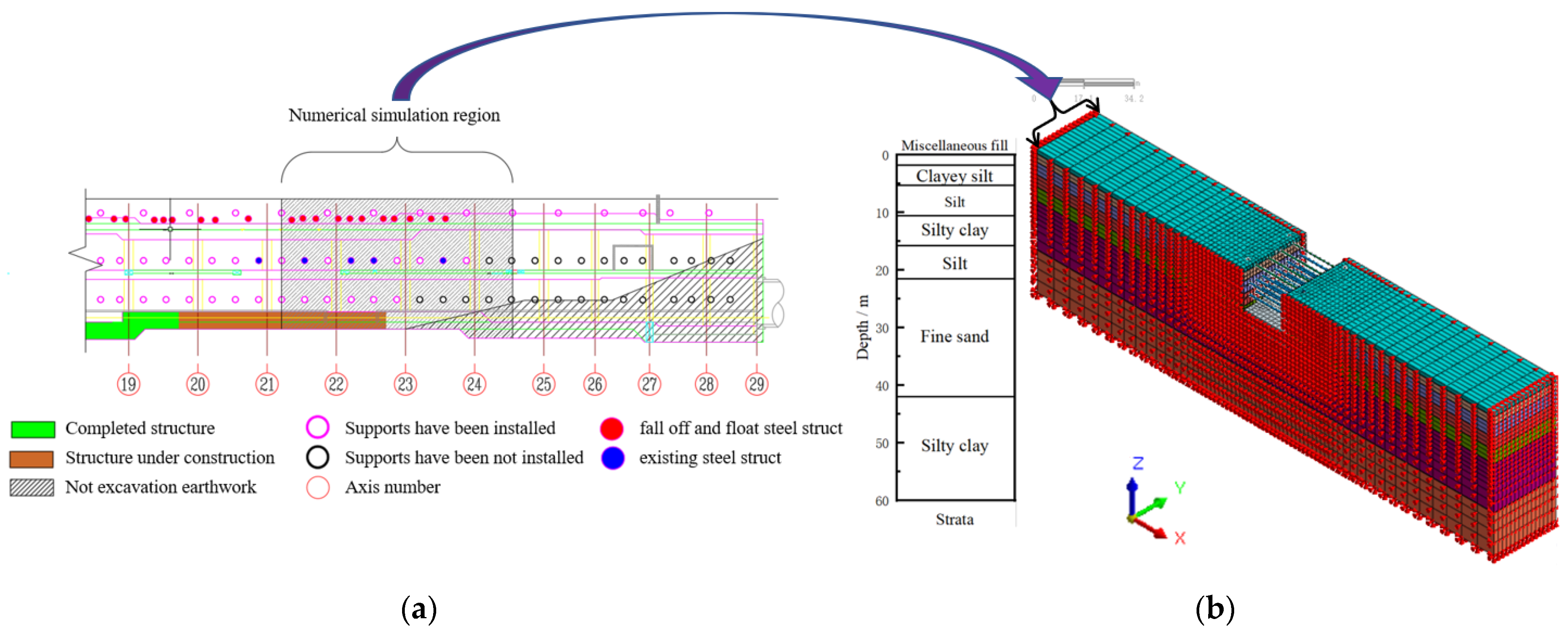
Xiaonangang Station is located at the intersection of the Zhengzhou–Kaifeng logistics channel and Zhengxin Road, which is laid along the Zhengzhou–Kaifeng logistics channel. Xiaonangang Station is the 23rd station in the first phase project of Zhengzhou metro line 8, which has no control buildings around the station. Figure 1a presents the foundation pit plan of Xiaonangang Station, where the pit was 238.95 m long, 21.1 m wide, and 17.14 m deep. In the pit, a bored pile and three layers of steel struts were adopted as the supporting structure, and the three-axis mixing piles were set as the water curtain. The cross-sectional design of this pit is displayed in Figure 1b.
2.2. Risk Analysis of 20 July Heavy Rainstorm in Zhengzhou
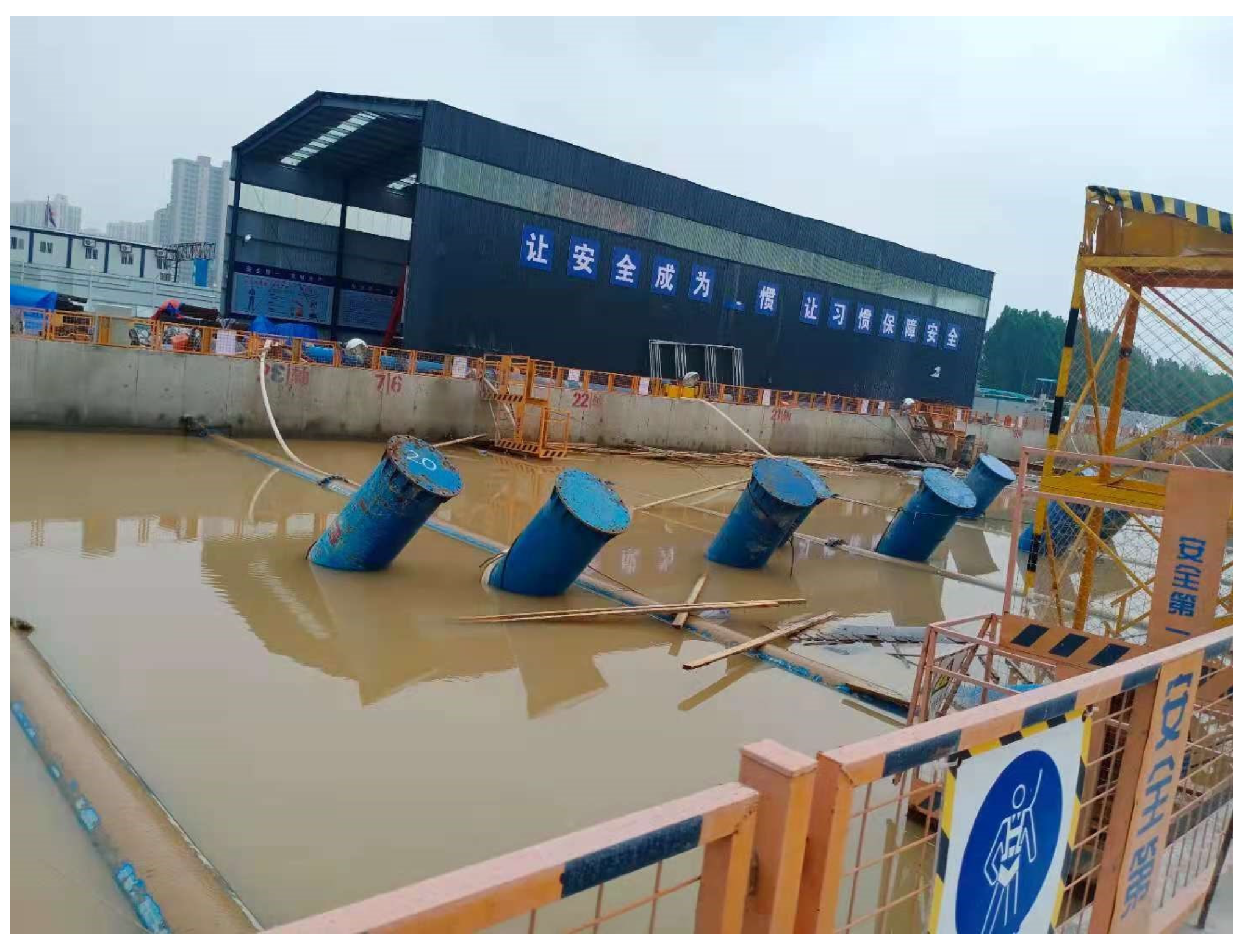
During the Xiaonangang Station excavation at the 23 axis and 24 axis, the 20 July heavy rainfall event in Zhengzhou city took place. The heavy rainfall was mainly concentrated at 16:00 to 20:00 on 20 July 2021, with a single day rainfall of 201 mm/h. From 19 to 20 July, the rainfall was 552.5 mm. Figure 2 presents the disaster scene map of Xiaonangang Station.
The mainly influence on the Xiaonangang foundation pit by heavy rain concentrated on the afternoon of 20 July 2021 to early morning of 21 July:
At 15:00 on 20 July, there was moderate rain, the rain water in the southwest side of the supporting structure and the shield well was deep, and there was a leakage point between the 17 and 18 axis of the foundation pit.
From 15:00 to 16:00 on 20 July, the rain gradually increased, the staff tried to use geotextile, quick drying cement, and drainage pipes to block and drain.
From 16:00 to 20:40 on 20 July, there was continuous heavy rainfall, were areas with deep water were pumped.
From 20:40 to 21:30 on 20 July, the Dongfeng River, which is located to the west of the station, burst, and there was 40 cm of water on the ground, with a rapid rising trend. It was decided to conduct guided recharge for the Xiaonangang foundation pit.
From 00:00 to 01:15 on 21 July, the Xiaonangang foundation pit was backfilled with water to the third steel strut.
From 03:30 to 04:00 on 21 July, Xiaonangang Station filled with water, and the second and third steel strut appeared in an ascending condition.
Affected by the heavy precipitation, the ground surface and surrounding roads of Xiaonangang Station were completely flooded, the water was about 1.5 m deep, and part of the steel strut fell off. According to the actual situation of the site, the foundation pit of Xiaonangang Station was judged as a super dangerous foundation pit.
2.3. Analysis of Monitoring Data
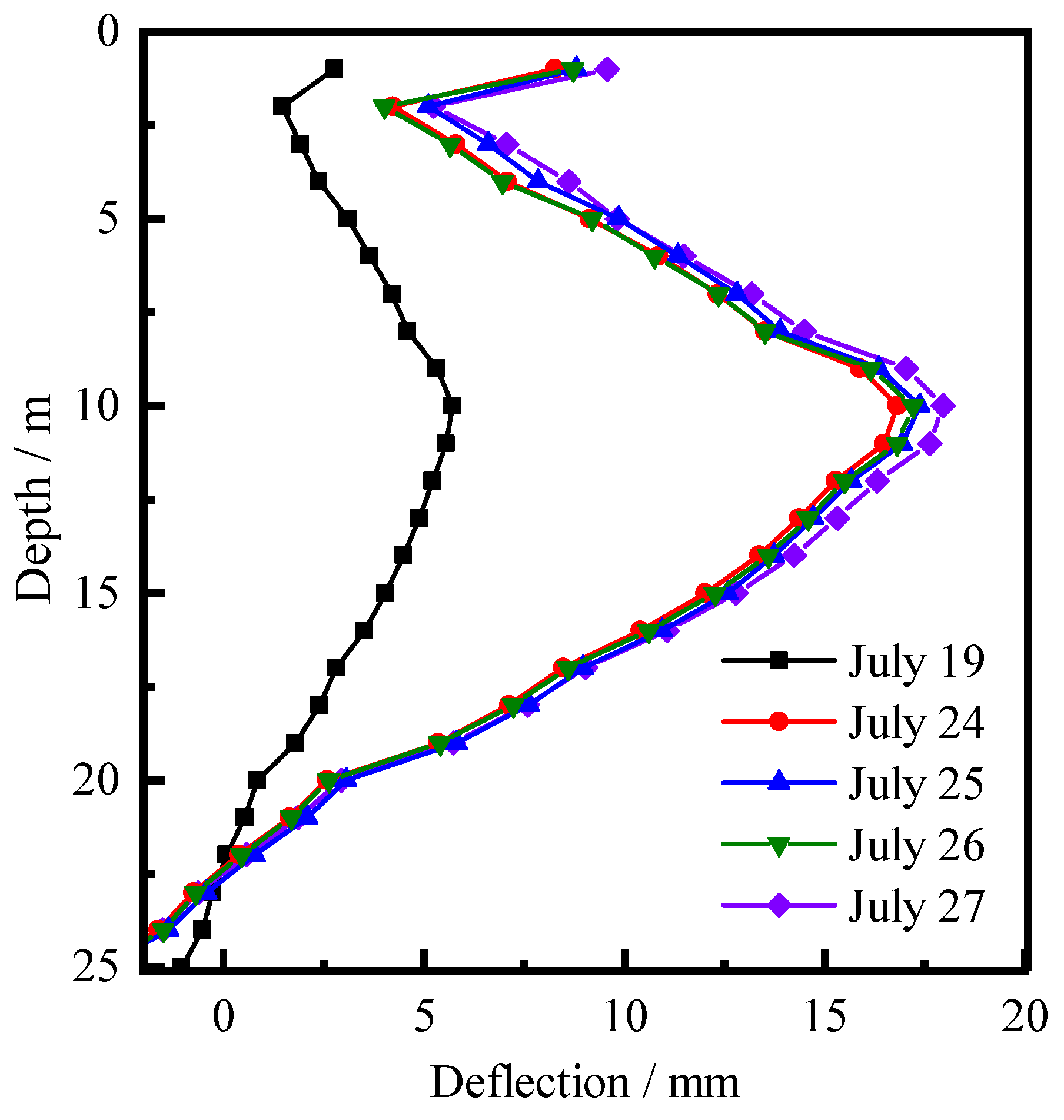
The steel strut of the Xiaonangang foundation fell off and floated due to the heavy rain, and the wall deflection had a larger displacement. Deformation results of a typical section of the foundation pit are given in Table 1 and Figure 3:
Combined with Table 1 and Figure 3, the lateral displacement had a great displacement during the 7.20 Henan rainstorm, and the average deformation rate reached 2.10 mm/day. After the rainstorm, the change in the wall deflection was relatively stable, and the average deformation rate was below 1 mm/day. Comparative analysis of the deformation rate of the foundation pit supporting structure before and after the rainstorm showed that the large deformation in the supporting structure was caused by the rainstorm.
3. Establishment of the Numerical Model
3.1. Basic Assumptions of Model Establishment
In order to simplify the modeling process and improve the calculation speed, the basic assumptions were as follows:
- (1)
- The ground surface at the back of the supporting structure is horizontal and the strata are evenly distributed;
- (2)
- The soil is isotropic;
- (3)
- The reinforcement and concrete of the supporting structure are considered as a whole, and the bored pile is simplified as a 0.9m thick diaphragm wall for simulation according to the idea of the equal cross-sectional moment of inertia;
- (4)
- The supporting structure of the foundation pit is an ideal elastic body, and the leakage between retaining piles is not considered;
- (5)
- The foundation pit is divided into four times of excavation, the first excavation to the first strut 0.5 m, the second excavation to the second strut 0.5 m, the third excavation to the third strut 0.5 m, and the fourth excavation to the bottom of the pit.
3.2. Determination of Model Size and Parameters
According to the soil layer distribution of the engineering, the soil layer parameters are shown in Table 2. Considering the influence range of dewatering well pumping [33], the soil behind the supporting structure on both sides of the foundation pit was taken as 100 m, and the length was in a 30 m range with large deformation due to heavy rain. The overall size of the model was taken as 30 × 221 × 60 m, and the calculation model and steel strut distribution are given in Figure 4. We constrained the normal displacements around the bottom of the model. The diaphragm wall was made of C35 concrete, the elastic modulus was 31.5 GPa, and the volumetric weight was 25 kN/m3. The elastic modulus of the steel strut was 206 GPa, and the volumetric weight was 78.5 kN /m3.
3.3. Selection of Soil Constitutive
The selection of the soil constitutive model is the key to the success of numerical simulation. The current soil constitutive models can be divided into four categories: ① elastic models such as the linear elastic theory model, D-C model, etc.; ② the ideal elastoplastic model such as the MC model, DP model, etc.; ③ the hardening strain model such as the MCC model and HS model; and ④ the small strain model such as the HS-Small model, tangent stiffness model, etc. [34,35,36].
Foundation pit excavation is a typical unloading deformation problem [37]. The handing ability of different constitutive models for soil unloading deformation should be considered when selecting constitutive models.
The elastic model obeys the generalized Hook’s law, which is often used to simulate hard rock, but rarely used in soil simulation. The MC model, which is a representative model of the elastic–plasticity model, but does not consider the unloading and then loading of the soil modulus to be significantly greater than the first load modulus relation, so the simulation results tend to make the surrounding soil uplift and not according to the engineering practice, and the deformation characteristics of foundation pit excavation are unable to be simulated well. The hardening strain model, represented by the MCC and HS constitutive models, can distinguish the stiffness between the loading and unloading because it is considered as the hardening characteristic of soil, which is more suitable for the simulation of foundation pit excavation. The small strain model can characterize the more complex properties of soil, but it needs more parameters, which often require special tests to determine [38,39,40].
Obviously, one that can distinguish between the loading and unloading stiffness of the hardening strain type model is more suitable for this kind of foundation pit excavation simulation. Considering the MCC model parameters are difficult to obtain [41], it is generally used in the simulation of the soft soil and clay, and the Zhengzhou city region in HuangFan District [34] is mostly sand soil and silt soil, so the HS model is more suitable than the MCC model for the simulation of sand soil. Therefore, this paper adopted the HS model for the foundation pit simulation.
3.4. Analysis of the Simulation Results
According to the above engineering background, the assumed conditions and related parameters, the rainfall analysis conditions were established as shown in Table 3, and Figure 5 presents the contrast between the numerical simulation and monitoring:
Following Figure 5, when the foundation pit was excavated to the bottom, both the numerical simulation and monitoring the maximum displacements of the supporting structure appeared in the range of 11 m~13 m below the ground surface, and the difference in the maximum displacement was only 0.65 mm. After heavy rainfall, the supporting structure had great deflection, but the overall deformation trend was still a parabolic shape. The maximum deformation was 16.96 mm in numerical simulation and 16.47 mm in engineering monitoring, which were close to each other. Moreover, there was an obvious settlement groove in the soil outside the foundation pit. This indicates that the simulation deformation trend of the foundation pit supporting structure had a similar trend to the monitoring. Both of them showed a parabolic shape with small deformation in the upper part, large deformation in the middle part, and almost no deformation at the bottom. This shows that the numerical simulation exhibited a good result with the engineering monitoring results. The simulation assumption, calculation condition, and method are reliable, furthermore, the modal approach can provide a basis for further analysis.
4. Deformation and Stress Analysis of Foundation Pit before and after Rainfall
4.1. Deformation and Stress Characteristics of Foundation Pit Excavation
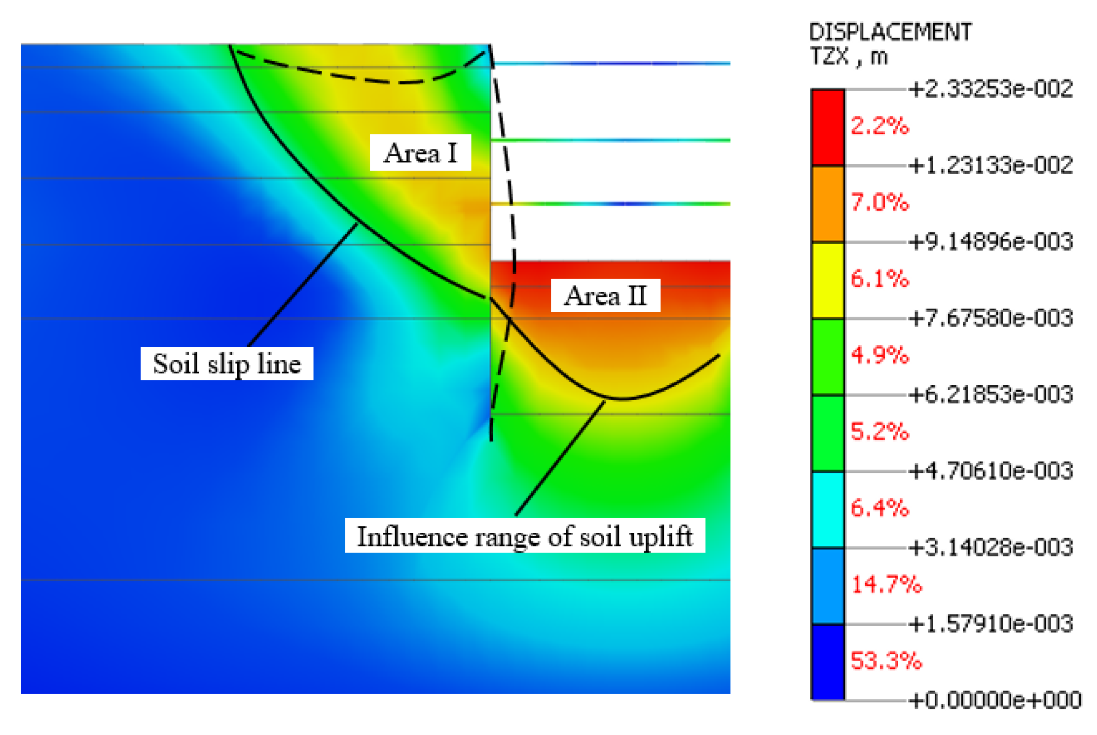
The excavation of a deep foundation pit will lead the stress field and displacement field of the surrounding soil to change, thus resulting in settlement of the ground surface, and the supporting structure will have a lateral displacement due to the soil compression. The finite element software was used to simulate the excavation of the foundation pit, and Figure 6 summarizes the partition diagram of the displacement and deformation characteristics. According to the deformation characteristics of the displacement field, the soil can be divided into two parts [42].
- (1)
- Area Ⅰ, In the Rankine active earth pressure zone, the soil displacement is mainly manifested as the squeezing into the pit and the soil subsidence;
- (2)
- Area Ⅱ, In the Rankine passive earth pressure zone, the soil displacement in this area mainly shows upward uplift due to the influence of excavation unloading and extrusion of the supporting structures on both sides.
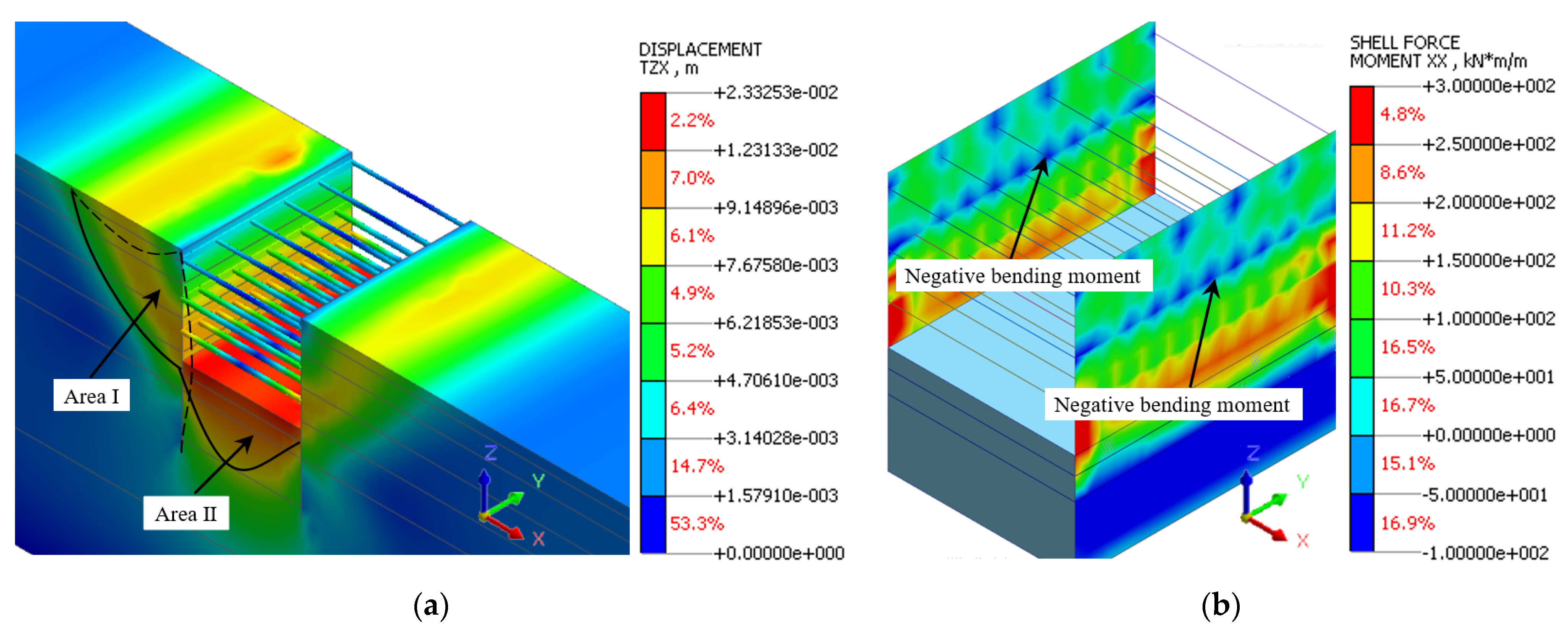
The displacement deformation diagram after excavation to the bottom of the foundation pit is displayed in Figure 7a. After excavation to the bottom, the soil on both sides of the foundation pit will settle and push into the pit, the maximum settlement point appears at the overload of the crane on the left side, and the soil extrusion into the pit will cause the maximum deformation of the supporting structure at 12~14 m below the ground surface. The soil at the bottom had a maximum 23.33 mm uplift due to the unloading rebound of soil. When the excavation reached the bottom of the pit, the overall deformation of the pit corresponded to the deformation area characteristics shown in Figure 6, that is, both sides of the foundation pit extruded into the pit, and the bottom of the foundation pit rose upward. From the deformation data, the deformation of the foundation pit is controllable and all deformation indices are in a safe range.
Figure 7b presents the bending moment diagram of the supporting structure after excavation to the bottom of the foundation pit. When the foundation pit is excavated to the bottom, the maximum bending moment of the supporting structure appeared above the excavation surface. With the influence of the steel strut, the inflection point of the bending moment appeared close to the connection point between the steel strut and supporting structure, and there was a negative bending moment at the joint. The maximum bending moment was located above the excavation surface, which was 218 kN·m. In contrast, the strut 3 steel did not have a negative bending moment due to the larger bending moment of the deep excavation, but the effect of the steel strut reduced the extreme value of the positive bending moment. It can be seen that the existence of the steel struct had a positive effect on weakening the internal force of the supporting structure and reducing the deformation of the foundation pit.
4.2. Deformation and Stress Analysis of Foundation Pit after Rainfall
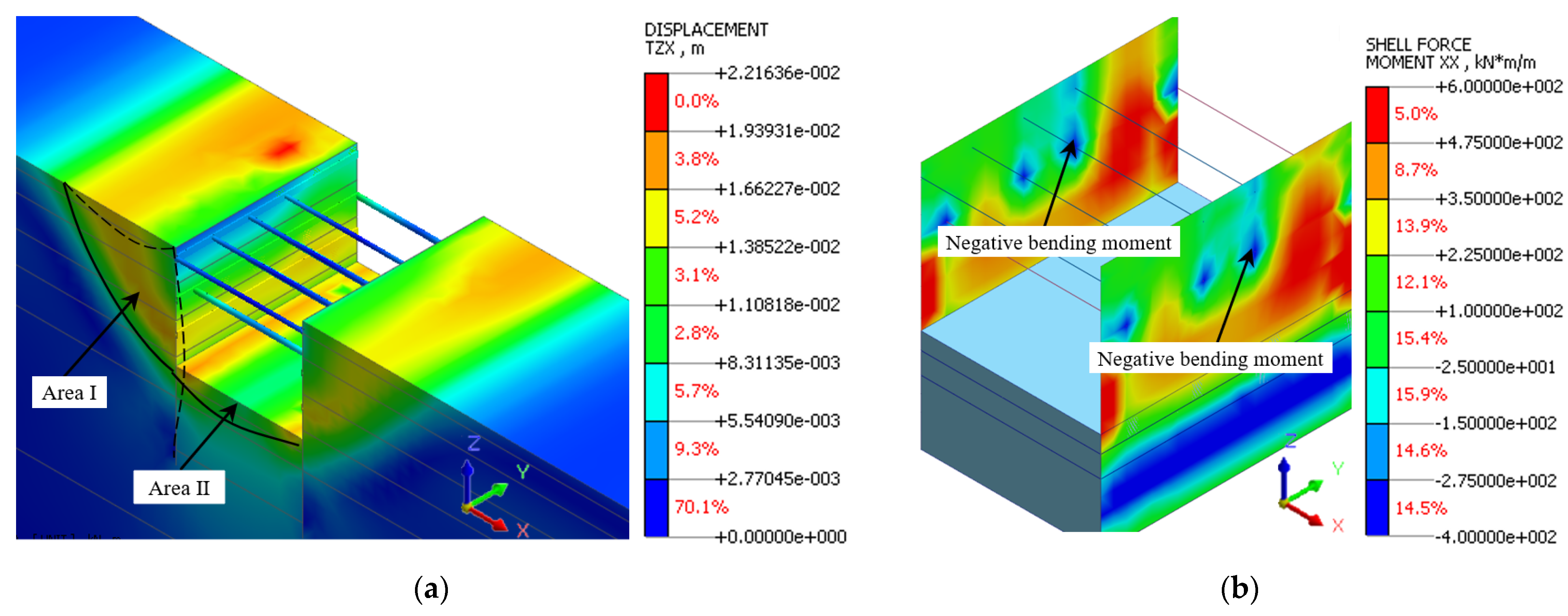
Figure 8a presents the deformation diagram of the foundation pit after the 7.20 Henan rainstorm. The deformation partition characteristics of the foundation pit did not change obviously after the heavy rainstorm, which still exhibited two obvious deformation partition characteristics. In contrast, the deformation of the Rankine active earth pressure area increases significantly, and the maximum settlement of a typical section was −14.73 mm. In contrast, the deformation of the passive earth pressure area decreased significantly, and the maximum uplift of the pit bottom decreased to 15.56 mm under the action of water pressure after recharging water. The surface settlement range expanded as the steel strut fell off; furthermore, the surface settlement trough in the falling off range of the first and second strut was obviously larger than other places without falling off. The maximum lateral deformation occurred in the range of 10–13 m below the ground surface, with an extreme value of 16.96 mm. This behavior indicates that the shedding of the strut 3 steel weakened the supporting effect of the supporting structure on the soil, and the maximum lateral displacement shifted upward.
Figure 8b presents the bending moment diagram of the supporting structure after the 7.20 Henan rainstorm. There was still a negative bending moment at the remaining steel strut joints; moreover, the steel strut shedding increased the overall bending moment of the supporting structure. The maximum bending moment was 538.53 kN·m, which was located at 9 m below the ground surface, which was significantly increased compared with that before the rainfall. The falling off of the strut 3 steel made the extreme bending moment of the support structure shift upward, and obviously, the change trend of the bending moment and deformation of the supporting structure corresponded.
Based on the foundation pit deformation and supporting structure stress cloud image before and after the July 7.20 rainstorm in Zhengzhou city, the rainfall expanded the deformation range on both sides of the foundation pit, in particular, the soil slip line was more obvious; conversely, it would weaken the uplift caused by unloading at the bottom of the foundation pit. Due to the 7.20 Henan rainstorm, the displacement and bending moment of the supporting structure of the foundation pit increased significantly, and the deformation rate reached 1.83 mm/d. The maximum displacement point and the maximum bending moment point all increased compared with that before the heavy rain.
5. Analysis of Effect Factors of Rainfall on Foundation Pit
Before the rainstorm, the water level in the pit had been dewatering to 1 m below the excavation surface. Rainfall will increase the saturation of the surface soil inside and outside of the pit, and weakening of the friction between soil particles will cause the soil softening. With the rainfall infiltration, the unit weight of soil will increase; a short time heavy rainfall caused 1.5 m deep water outside the pit. Some leakage points appeared due to the water pressure difference between two sides of the supporting structure. The pit filled with water, which made some steel struts fall off. In order to research the influence factors of heavy rainfall on the deep foundation pit, the numerical simulation method was used to carry out single factor analysis, and several factors were analyzed, respectively, which may cause the supporting structure and surface settlement to change. The calculation results are displayed in Figure 9.
5.1. Effect of Soil Softening
The influence range of rainfall on the soil is about 0.9 m deep [4,43], so the range of soil softening and severity increase was 1 m below the ground surface and 1 m below the excavation surface of the foundation pit. The softening degree is the reduction in the elastic modulus by 40% [3]. The displacement of the foundation pit supporting structure and the ground surface settlement before and after soil softening are shown in Figure 9a.
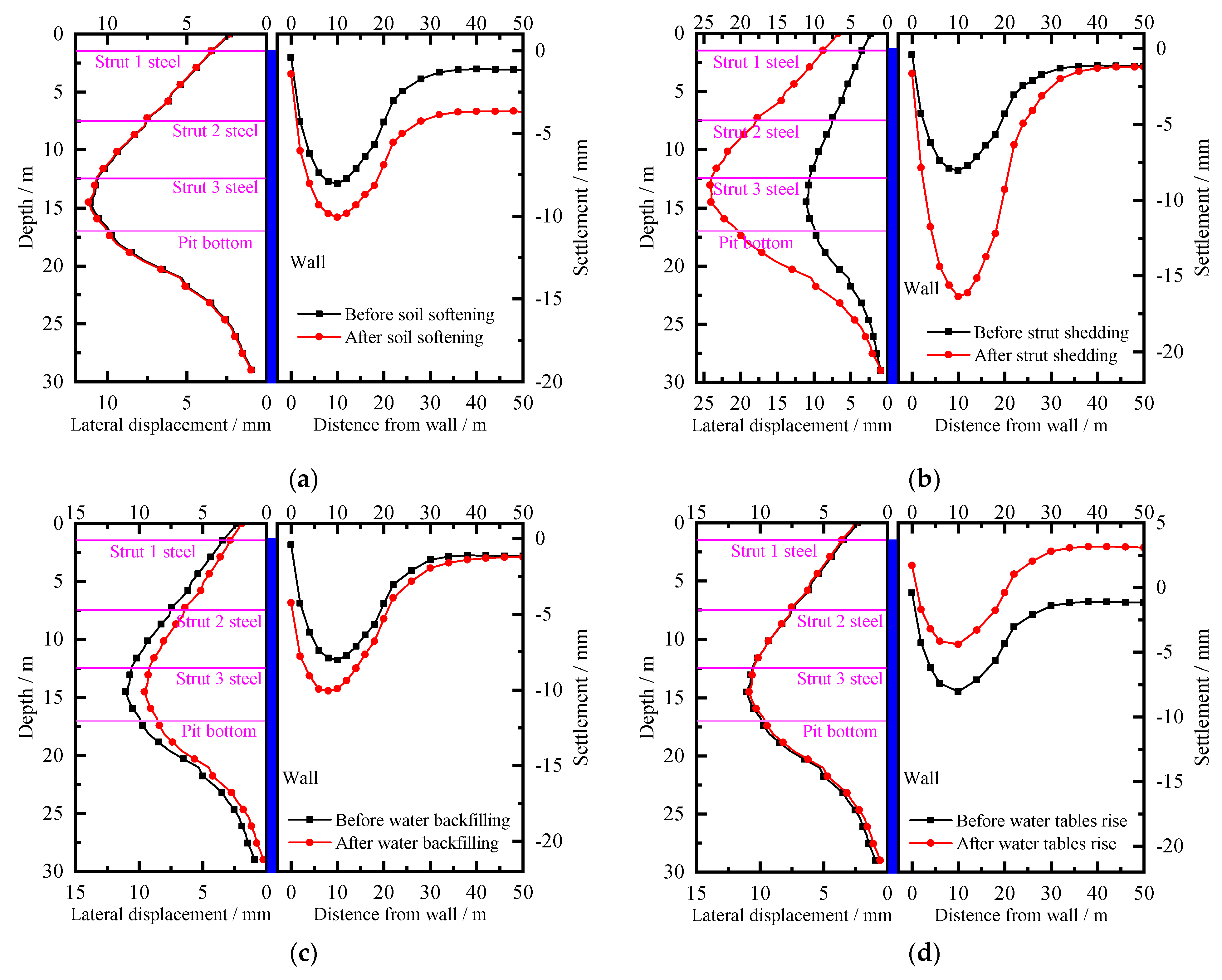
When the soil inside the pit softened and the unit weight of soil outside the pit increased, the maximum displacement of the supporting structure increased from 11.05 mm to 11.17 mm by 0.12 mm, an increase of 1.09%. The soil outside the pit exhibited obvious settlement, and the maximum settlement increased from −8.04 mm to −10.08 mm, an increase of 25.37%. The softening of soil had little influence on the supporting structure of the foundation pit; however, it had a great influence on the ground surface settlement outside the pit.
5.2. Effect of Water Load
The deepest water of about 1.5 m gathered around the site due to the action of heavy rainfall. We set the working conditions as follows: Working condition 1: There is no water load inside and outside the foundation pit; Working condition 2: There is 1.5 m deep water only outside the foundation pit; Working condition 3: There is only a 1.5 m deep water load in the foundation pit; Working condition 4: There is a 1.5 m deep water load inside and outside the foundation pit. The water pressure was set to simulate the water load. The maximum lateral displacement of the pile body and pile top displacement under four working conditions are given in Table 4.
When the water load was only applied to the active area outside the foundation pit, the maximum displacement of the supporting structure increased by 0.25 mm, and the displacement of the pile top increased by 0.6 mm. When the water load was only applied in the foundation pit, the deformation of the supporting structure was slightly reduced, but the overall change was not great. When the water load was applied to both inside and outside the foundation pit, the deformation of the support structure was smaller than that of working condition 2, which indicates that the water in the foundation pit has a weakening effect on the deformation of the supporting structure.
5.3. Effect of the Steel Strut Falls Off
Across the whole process of foundation pit excavation, the stability of the steel strut determines the stability of the protection of the whole foundation pit. The steel strut shedding at the Xiaonangang Station foundation pit was simulated and the results of the supporting structure deformation and surface settlement are shown in Figure 9b.
When the steel strut fell off, the lateral displacement of the supporting structure and the settlement of soil outside the pit both changed greatly. The maximum displacement of the supporting structure increased by 12.96 mm to 24.01 mm from 11.05 mm, an increase of 117.29%, and the pile top tended to move into the pit. The maximum surface settlement outside the pit increased from −8.04 mm to −16.36 mm by 8.32 mm, an increase of 103.48%. Apparently, the falling off of the steel strut had a great impact on the supporting structure and surrounding surface, which greatly reduces the safety of the foundation pit engineering. This also shows that the steel strut is crucial to the construction of the foundation pit.
5.4. Effect of Foundation Pit Backfill Water
After the retaining wall of the foundation pit is broken for the guided water recharge, the water is quickly refilled inside the foundation pit. Taking the ground surface as the zero point of the water level, a water pressure with a water level of 1.5 m was set on the inner side of the foundation pit supporting structure and the bottom of the pit to simulate the influence of the foundation pit backfilling with water. The lateral displacement of the wall and surface settlement deformation before and after the foundation pit backfilled with water are given in Figure 9c.
After the whole foundation pit filled with water, the supporting structure had a tendency of displacement to the outside of the pit, and the displacement of the supporting structure decreased from 11.05 mm to 9.58 mm by 1.47 mm, a decrease of 13.30%. The soil outside the pit had no obvious settlement change, but the settlement trough moved slightly to the pit.
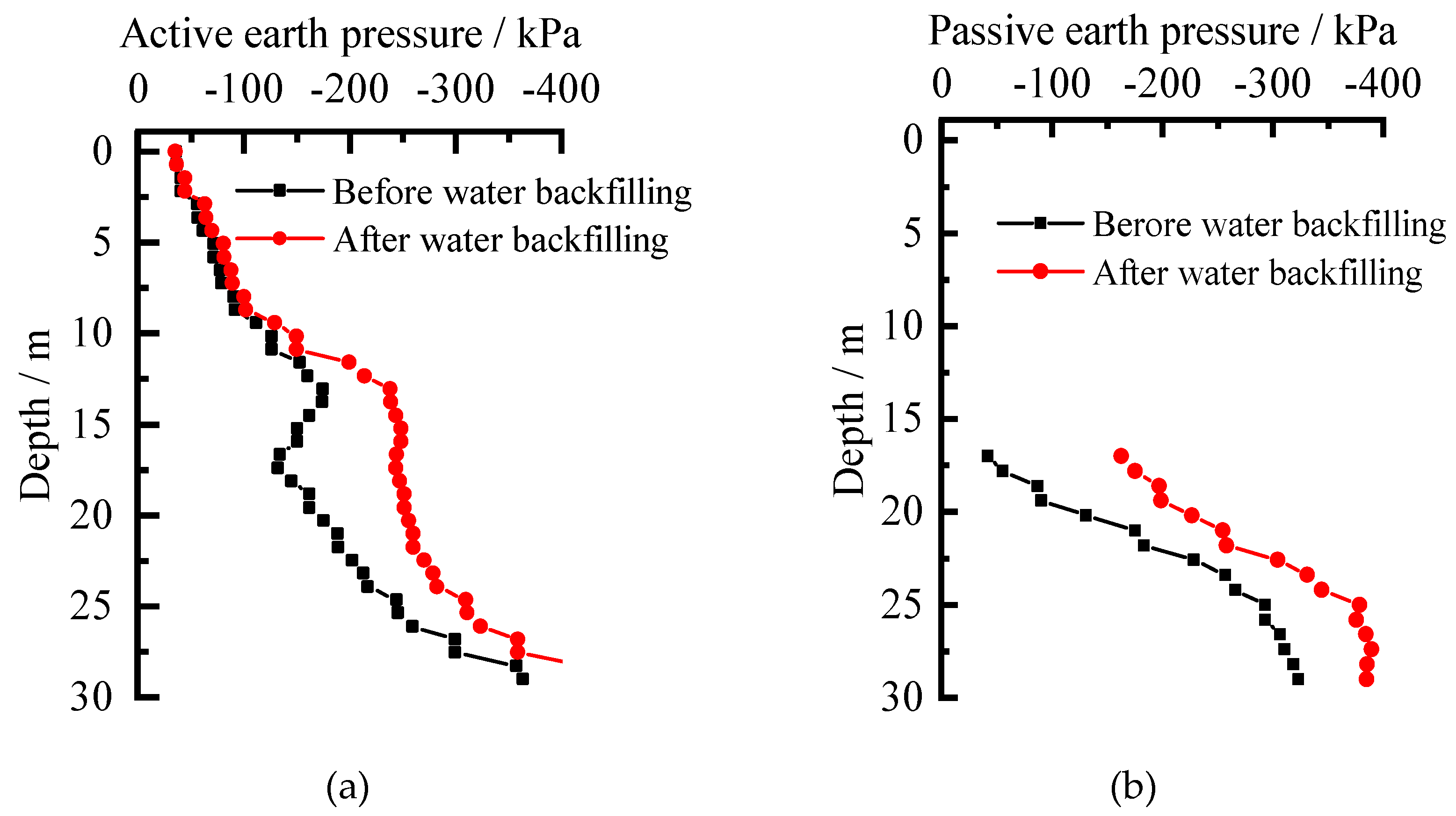
From Figure 9c, the influence of the backfill water weakened the deformation of the supporting structure. Figure 10 presents the variation in the soil pressure on both sides of the supporting structure before and after water backfilled in foundation pit. Pit recharge water increased the inside of the water and soil pressure of the supporting structure of the foundation pit; furthermore, the water pressure produced a lateral normal force to the supporting structure, which reduced the soil and water pressure difference on both sides of the supporting structure, and weakened the active soil pressure on the supporting structure deformation, so the supporting structure has a “rebound” phenomenon.
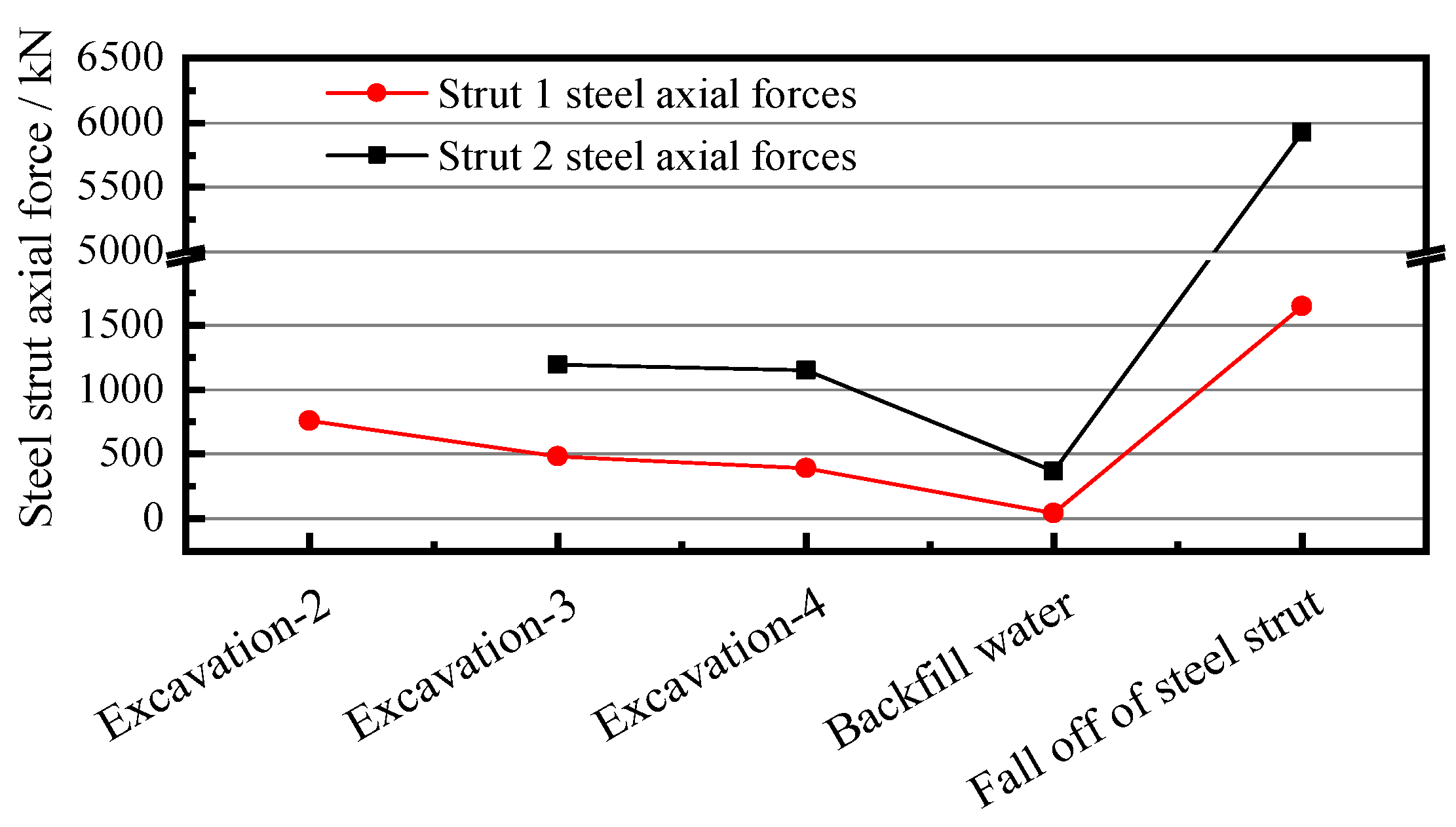
Figure 11 presents the steel strut axial force variation by rainstorm. Before the rainstorm, the maximum axial force of the first strut was 390 kN, and the maximum axial force of the second strut was 1150 kN. When the rainstorm was over and the struts had not fallen off, the maximum axial force of the first strut decreased by 348 kN to 42 kN, the maximum axial force of the second strut decreased by 783 kN to 367 kN, and when the struts fell off, the axial force of the strut increased greatly.
When the foundation pit was backfilled with water, the supporting structure had a smaller deformation to the outside, and this deformation caused some steel struts to not connect with the circumference purlin fully, so the axial force of the strut was reduced. Because of the buoyancy in water, the connection between the steel strut and circumference purlin eventually fails and the strut floats up. The steel strut falling off results in an incomplete support system, so the soil pressure behind the wall makes the supporting structure produce a large displacement into the pit, which compacts the remaining steel strut and results in a great increase in the axial force of the remaining strut.
5.5. Effect of Rising Water Tables
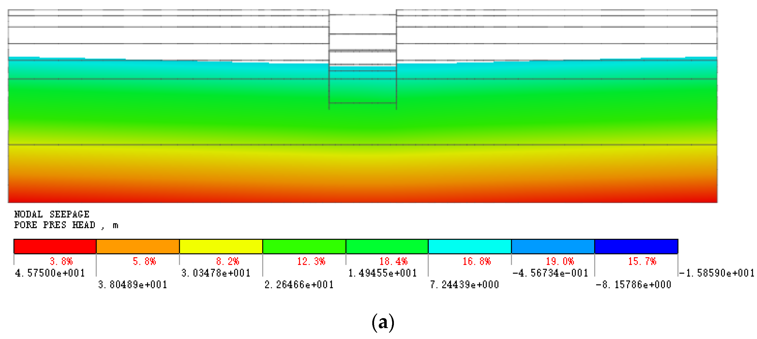
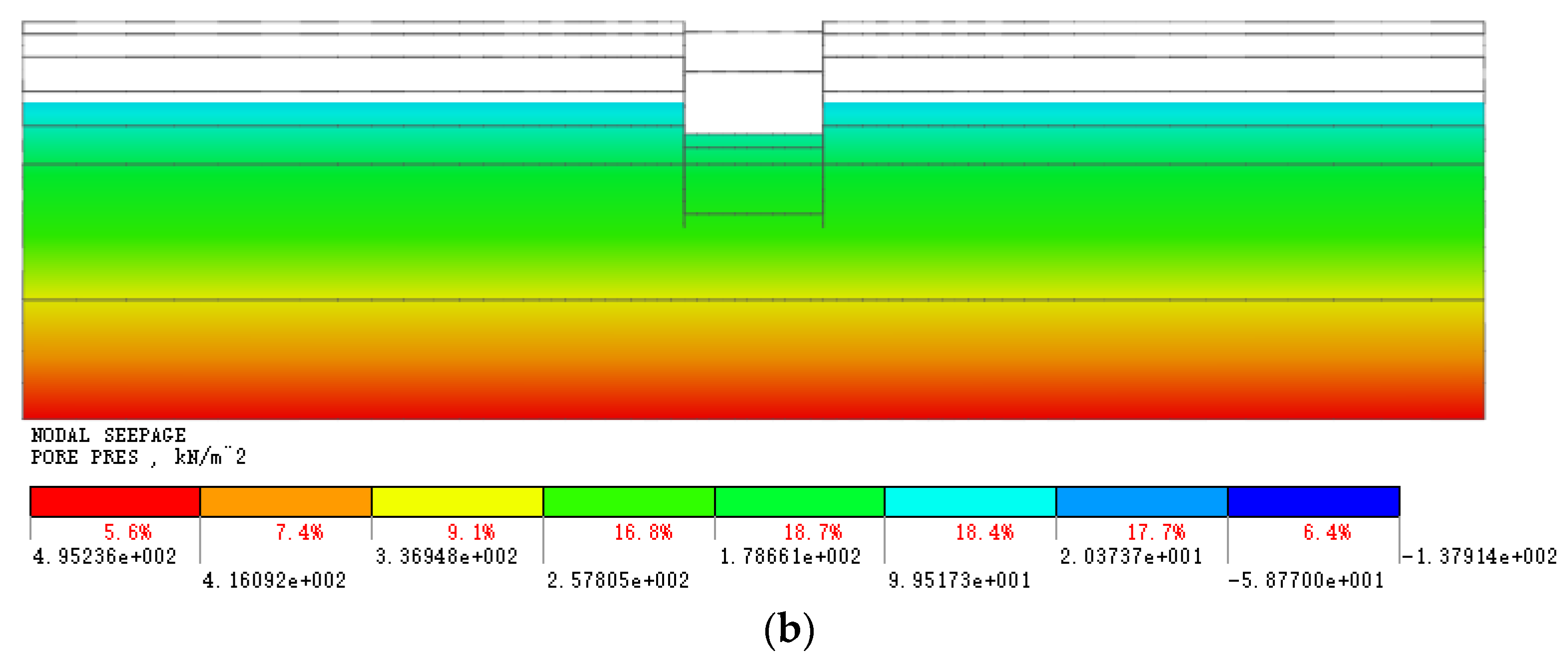
In the process of the rainstorm, the groundwater level around the foundation pit rose obviously and some leakage points were produced in the supporting structure. The simulation of the groundwater level rise used a simplified treatment, and did not consider the leakage points of the supporting structure. After the rise in the groundwater level, the value of total pore pressure difference inside and outside the pit increased, and the underground water level rose from 14.25 m to 9.5 m. The pore pressure distribution on both sides of the foundation pit before and after the groundwater level rise is displayed in Figure 12.
Figure 9d presents the deformation of the foundation pit supporting structure and surface settlement before and after the rises in the groundwater level. Under this condition, there was no obvious deformation of the supporting structure, nevertheless, the ground surface produced an obvious uplift, and the maximum settlement decreased by 3.65 mm to −4.39 mm from −8.04 mm, which decreased by 45.39%. The rise in the groundwater level had little influence on the supporting structure of the foundation pit, but the ground surface showed an obvious tendency of uplift.
5.6. Analysis of Prevention and Control Measures
The above analyses prove that the shedding of the steel strut had the largest impact on the supporting structure of the foundation pit, followed by the impact of water backfilling water, and these two factors had the opposite effects on the supporting structure of the foundation pit. The soil softening in the rainfall infiltration area and the water loading above the soil mainly affected the soil settlement outside the foundation pit, but only had little effect on the supporting structure. The rise in the underground water level made the ground surface uplift, and had little influence on the supporting structure.
Based on the above analysis of the 20 July rainstorm in Zhengzhou city, deep foundation pit engineering can be protected from inside the foundation pit and outside the foundation pit when faced with heavy rainfall. The protection from outside the foundation pit should include raising the height of the original retaining wall before the rainfall to prevent water flowing into the foundation pit and causing water in the pit. If the rainstorm is too large and the water in the pit cannot be discharged in time, the retaining wall of the foundation pit should be demolished and guided recharge to the foundation pit can be conducted to reduce the pressure difference between the two sides of the supporting structure and maintain the stability of the foundation pit. Furthermore, before conducting guided recharge water, it is necessary to reinforce the connection between the strut and Wai purlin, and improve the original shedding prevention measures, which can prevent the strut from falling off, thus causing harm to the foundation pit.
6. Conclusions
This paper reports on the foundation pit effect by heavy rainfall. The observed lateral displacement of the diagram wall and surface settlement were analyzed. Then, some numerical models considering different influencing factors of rainfall were established to simulate the rainfall effect. The deformation mechanism and effect factors of the rainfall process on the foundation pit were analyzed. The following conclusions can be obtained from this study:
- (1)
- The results of simulating the rainfall effect on the deep foundation pit by the finite element software was good, the stress and strain states of the soil and supporting structure could be obtained in the simulation, while the results of the simulation were in good agreement with the monitoring data, which shows that the reliability of the numerical simulation and the calculation results can provide a reference for similar projects.
- (2)
- The 20 July heavy rainstorm in Zhengzhou city caused the typical foundation pit to undergo a signification change in the supporting structure and surface settlement. Under the failure of the first- and second-layer steel strut, the soil subsidence range had a signification increase. Under the failure of the third layer steel strut, the supporting effect of the supporting structure on the soil weakened, which led to the maximum bending moment and maximum displacement of the supporting structure to increase and move up in difference degrees.
- (3)
- The main factors affecting the deep foundation pit by heavy rain were the steel strut falling off and water filling in the whole pit, while the influence of the rise in the water tables, water load, and soil softening had a low effect. Among them, the backfill water increased the water pressure in the inner side of the supporting structure, which weakened the soil and the water pressure difference on both sides of the supporting structure. This weakened the deformation of the supporting structure and caused the steel strut to fall off; furthermore, the failure of the strut led to a greater deformation of the foundation pit.
- (4)
- When the foundation pit engineering suffers from a rainstorm, there is a positive significance in raising the retaining wall outside the foundation pit to prevent water accumulation. When the water accumulation is too deep, the retaining wall should be broken and guided recharge could weaken the deformation of the supporting structure, but the connection between the steel support and enclosing purlin should be strengthened in time before the recharge.
Author Contributions
Conceptualization, X.W. and J.X.; Methodology, J.X.; Software, J.X. and Y.L; Validation, X.W. and T.Z.; Formal analysis, J.X.; Data curation, J.X.; Writing—original draft preparation, J.X.; Writing—review and editing, J.X. and T.Z.; Project administration, X.W. and Y.L. All authors have read and agreed to the published version of the manuscript.
Funding
This research was funded by the National Natural Science Foundation of China (No. 51309100), Science and Technology Project of Henan Province (No. 222102320014).
Data Availability Statement
The data presented in this study are available on request from the corresponding author.
Conflicts of Interest
The authors declare no conflict of interest.
References
- China Association of Metros. Available online: https://www.camet.org.cn/ (accessed on 20 May 2022).
- Troncone, A.; Pugliese, L.; Conte, E. Rainfall Threshold for Shallow Landslide Triggering Due to Rising Water Table. Water 2022, 14, 2966. [Google Scholar] [CrossRef]
- Liu, C.; Ji, F.; Zheng, G.; Liu, T.; Liu, Y. Measurement and mechanism of influences of rainfall on supporting structures of foundation pits in soft soils. Chin. J. Geotech. Eng. 2020, 42, 447–456. [Google Scholar] [CrossRef]
- Meng, X.F.; Liao, H.J.; Zhang, J.W. Infiltration Law of Water in Undisturbed Loess and Backfill. Water 2020, 12, 2388. [Google Scholar] [CrossRef]
- Li, Y.L.; Chen, B.; Ma, C.; Zhou, F.P. Study on the stability of the foundation pit slope under rainfall infiltration conditions based on ABAQUS. Chin. J. Appl. Mech. 2017, 34, 155–161+203–204. [Google Scholar] [CrossRef]
- Ren, D.X.; Xue, P.; Ye, F.; Zhou, X.Y.; Gao, X.F.; Luo, D.L. Shallow slope stability analysis of cohesive soil foundation pit under rainfall infiltration. J. Chengdu Univ. Technol. 2022, 49, 204–212. [Google Scholar] [CrossRef]
- Cui, F.Z. Study on the Stability and Controlling Technology of Earth Deep Foundation Pit under Strong Rainfall. Doctoral Dissertation, China University of Mining and Technology, Beijing, China, 2016. [Google Scholar]
- Sorbino, G.; Nicotera, M.V. Unsaturated soil mechanics in rainfall-induced flow landslides. Eng. Geol. 2013, 165, 105–132. [Google Scholar] [CrossRef]
- Tang, C.-S.; Gong, X.-P.; Shen, Z.; Cheng, Q.; Inyang, H.; Lv, C.; Shi, B. Soil micro-penetration resistance as an index of its infiltration processes during rainfall. J. Rock Mech. Geotech. 2022, 14, 1580–1587. [Google Scholar] [CrossRef]
- Nagy-Göde, F.K.; Török, Á. Rainfall-Induced or Lake-Water-Level-Controlled Landslide? An Example from the Steep Slopes of Lake Balaton, Hungary. Water 2022, 14, 1169. [Google Scholar] [CrossRef]
- Yao, Z.; Yang, J.; Zhang, P.; Zhang, Y.; Liu, L.; Zhao, D. The Response Mechanisms of Topographic Changes in Small Loess Watershed under Rainstorm. Sustainability 2022, 14, 10472. [Google Scholar] [CrossRef]
- Wang, J.X.; Liu, X.T.; Wu, Y.B.; Liu, S.L.; Wu, L.G.; Lou, R.X.; Lu, J.S.; Yin, Y. Field experiment and numerical simulation of coupling non-Darcy flow caused by curtain and pumping well in foundation pit dewatering. J. Hydrol. 2017, 549, 277–293. [Google Scholar] [CrossRef]
- Dong, H.; Huang, R.Q.; Gao, Q.F. Rainfall infiltration performance and its relation to mesoscopic structural properties of a gravelly soil slope. Eng. Geol. 2017, 230, 1–10. [Google Scholar] [CrossRef]
- Yeh, P.T.; Lee, K.Z.Z.; Chang, K.T. 3D Effects of permeability and strength anisotropy on the stability of weakly cemented rock slopes subjected to rainfall infiltration. Eng. Geol. 2020, 266, 105459. [Google Scholar] [CrossRef]
- Cho, S.E. Prediction of shallow landslide by surficial stability analysis considering rainfall infiltration. Eng. Geol. 2017, 231, 126–138. [Google Scholar] [CrossRef]
- Kim, Y.; Jeong, S.; Kim, J. Coupled infiltration model of unsaturated porous media for steady rainfall. Soils Found. 2016, 56, 1071–1081. [Google Scholar] [CrossRef]
- Doležalová, M. Tunnel complex unloaded by a deep excavation. Comput. Geotech. 2001, 28, 469–493. [Google Scholar] [CrossRef]
- Shen, S.L.; Wu, Y.X.; Xu, Y.S.; Hino, T.; Wu, H.N. Evaluation of hydraulic parameters from pumping tests in multi-aquifers with vertical leakage in Tianjin. Comput. Geotech. 2015, 68, 196–207. [Google Scholar] [CrossRef]
- Gao, X.; Tian, W.-p.; Zhang, Z. Analysis of Deformation Characteristics of Foundation-Pit Excavation and Circular Wall. Sustainability 2020, 12, 3164. [Google Scholar] [CrossRef] [Green Version]
- Sun, Y.; Li, Z. Study on Design and Deformation Law of Pile-Anchor Support System in Deep Foundation Pit. Sustainability 2022, 14, 12190. [Google Scholar] [CrossRef]
- Su, T.; Zhou, Y.; Wang, Z.; Ye, S. Large Scale Model Test Study of Foundation Pit Supported by Pile Anchors. Appl. Sci. 2022, 12, 9792. [Google Scholar] [CrossRef]
- Zeng, C.-F.; Xue, X.-L.; Li, M.-K. Use of cross wall to restrict enclosure movement during dewatering inside a metro pit before soil excavation. Tunn. Undergr. Space Technol. 2021, 112, 103909. [Google Scholar] [CrossRef]
- Sun, Y.; Zhou, S.; Luo, Z. Basal-heave analysis of pit-in-pit braced excavations in soft clays. Comput. Geotech. 2017, 81, 294–306. [Google Scholar] [CrossRef]
- Guo, P.P.; Gong, X.N.; Wang, Y.X. Displacement and force analyses of braced structure of deep excavation considering unsymmetrical surcharge effect. Comput. Geotech. 2019, 113, 103102. [Google Scholar] [CrossRef]
- Zeng, C.F.; Zheng, G.; Zhou, X.F.; Xue, X.L.; Zhou, H.Z. Behaviours of wall and soil during pre-excavation dewatering under different foundation pit widths. Comput. Geotech. 2019, 115, 103169. [Google Scholar] [CrossRef]
- Xie, Z.F.; Shen, S.L.; Arulrajah, A.; Horpibulsuk, S. Environmentally sustainable groundwater control during dewatering with barriers: A case study in Shanghai. Undergr. Space 2021, 6, 12–23. [Google Scholar] [CrossRef]
- Zhou, N.Q.; Vermeer, P.A.; Lou, R.X.; Tang, Y.Q.; Jiang, S.M. Numerical simulation of deep foundation pit dewatering and optimization of controlling land subsidence. Eng. Geol. 2010, 114, 251–260. [Google Scholar] [CrossRef]
- Xu, X.B.; Hu, Q.; Huang, T.M.; Chen, Y.; Shen, W.M.; Hu, M.Y. Seepage failure of a foundation pit with confined aquifer layers and its reconstruction. Eng. Fail. Anal. 2022, 138, 106366. [Google Scholar] [CrossRef]
- Li, Z.; Luo, Z.J.; Xu, C.H.; Tan, J.Z. 3D fluid-solid full coupling numerical simulation of soil deformation induced by shield tunnelling. Tunn. Undergr. Space Technol. 2019, 90, 174–182. [Google Scholar] [CrossRef]
- Cheng, Y.C.; Zhang, R.H.; Wang, K.H.; Ai, Z.Y. Time-dependent behavior of retaining piles during pre-excavation dewatering in multi-layered saturated soils. Comput. Geotech. 2021, 137, 104300. [Google Scholar] [CrossRef]
- Wang, K.W.; Yang, X.H.; Liu, X.M.; Liu, C.M. A simple analytical infiltration model for short-duration rainfall. J. Hydrol. 2017, 555, 141–154. [Google Scholar] [CrossRef]
- Shen, S.-L.; Wu, Y.-X.; Misra, A. Calculation of head difference at two sides of a cut-off barrier during excavation dewatering. Comput. Geotech. 2017, 91, 192–202. [Google Scholar] [CrossRef]
- Li, X.B.; Hou, X.M.; Li, Y.D. A finite element method for calculating the influence radius of foundation pit dewatering. Rock Soil Mech. 2021, 42, 574–580. [Google Scholar] [CrossRef]
- Wang, D.; Wang, G.F.; Lu, L.H.; Cao, Z.L.; Xu, Q.W. Suitable constitutive model of pit in thick alluvial clay along Huanghe River. J. Civ. Environ. Eng. 2019, 41, 36–47. [Google Scholar] [CrossRef]
- Hamidi, A.; Tourchi, S.; Kardooni, F. A critical state based thermo-elasto-plastic constitutive model for structured clays. J. Rock Mech. Geotech. 2017, 9, 1094–1103. [Google Scholar] [CrossRef]
- Ye, G.-l.; Ye, B. Investigation of the overconsolidation and structural behavior of Shanghai clays by element testing and constitutive modeling. Undergr. Space 2016, 1, 62–77. [Google Scholar] [CrossRef] [Green Version]
- Li, P.; Chen, Y.M.; Shen, Y. Simplified analysis method of pit rebound deformation. J. PLA Univ. Sci. Technol. (Nat. Sci. Ed.) 2012, 13, 88–91. [Google Scholar]
- Xu, Z.H.; Wang, W.D. Selection of soil constitutive models for numerical analysis of deep excavations in close proximity to sensitive properties. Rock Soil Mech. 2010, 31, 258–264+326. [Google Scholar] [CrossRef]
- Huang, A.J.; Wang, D.Y.; Wang, Z.X. Rebound effects of running tunnels underneath an excavation. Tunn. Undergr. Space Technol. 2006, 21, 399. [Google Scholar] [CrossRef]
- Kouretzis, G.P.; Sheng, D.; Wang, D. Numerical simulation of cone penetration testing using a new critical state constitutive model for sand. Comput. Geotech. 2014, 56, 50–60. [Google Scholar] [CrossRef]
- Chen, J.F.; Sun, H.; Shi, Z.M. Estimation of parameters of modified cam-clay model coupling biot theory. J. Tongji Univ. 2003, 05, 544–548. [Google Scholar]
- Jia, J.; Xie, X.L. Unloading Deformation Mechanism of Deep-large Excavationin Shanghai Clay Area. J. Shanghai Jiaotong Univ. 2009, 43, 1005–1010. [Google Scholar] [CrossRef]
- Sun, Z.H.; Jiang, C.; Xin, Q.M.; Shao, L.F. Study of the rainfall effect on soil-water characteristics and stability of deep excavation in unsaturated silty clay. Geotech. Investig. Surv. 2021, 49, 6–12+47. [Google Scholar]
Figure 1.
Design and construction overview of Xiaonangang Station. (a) The construction schedule; (b) cross sectional drawing.
Figure 1.
Design and construction overview of Xiaonangang Station. (a) The construction schedule; (b) cross sectional drawing.

Figure 2.
Disaster scene map of Xiaonangang Station.

Figure 3.
Lateral displacement of the pile at different times.

Figure 4.
Calculation model and steel strut distribution diagram. (a) Distribution map of the existing support and shed support. (b) Calculation model.
Figure 4.
Calculation model and steel strut distribution diagram. (a) Distribution map of the existing support and shed support. (b) Calculation model.

Figure 5.
The contrast between the numerical simulation and monitoring of the lateral displacement of the wall and ground settlement.
Figure 5.
The contrast between the numerical simulation and monitoring of the lateral displacement of the wall and ground settlement.

Figure 6.
Partition diagram of the displacement and deformation characteristics of the foundation pit excavation.
Figure 6.
Partition diagram of the displacement and deformation characteristics of the foundation pit excavation.

Figure 7.
Diagram of the deformation diagram of the foundation pit excavation and bending moment diagram of the support structure. (a) Deformation of foundation pit excavation; (b) bending moment of thee support structure.
Figure 7.
Diagram of the deformation diagram of the foundation pit excavation and bending moment diagram of the support structure. (a) Deformation of foundation pit excavation; (b) bending moment of thee support structure.

Figure 8.
Diagram of the deformation diagram of the foundation pit excavation and the bending moment diagram of the support structure after the 7.20 Henan rainstorm. (a) Deformation of the foundation pit after the 7.20 Henan rainstorm; (b) bending moment of the support structure after the 7.20 Henan rainstorm.

Figure 9.
Results of the numerical model calculation. (a) Lateral displacement of the wall and ground surface settlement before and after soil softening; (b) lateral displacement of the wall and ground surface settlement before and after steel strut shedding; (c) lateral displacement of the wall and surface settlement before and after water backfilling in the foundation pit; (d) lateral displacement of the wall and surface settlement before and after the rise in the groundwater level.

Figure 10.
Soil pressure before and after water backfilling in the foundation pit. (a) Outside the pit; (b) inside the pit.
Figure 10.
Soil pressure before and after water backfilling in the foundation pit. (a) Outside the pit; (b) inside the pit.

Figure 11.
Time–history curve of the steel strut axial force.

Figure 12.
Total pore pressure distribution on both sides of the foundation pit before and after the rise in the water tables. (a) Distribution of the total pore pressure before the rise in the water rise; (b) Distribution of the total pore pressure after the rise in the water tables.
Figure 12.
Total pore pressure distribution on both sides of the foundation pit before and after the rise in the water tables. (a) Distribution of the total pore pressure before the rise in the water rise; (b) Distribution of the total pore pressure after the rise in the water tables.


Table 1.
Lateral displacement increment of the pile before and after the rainstorm.
| Monitoring Data | Maximum Deformation/mm | Deformation Rate mm/Day | Working Condition |
|---|---|---|---|
| July 18 | 10.15 | -- | Rainfall |
| July 19 | 10.43 | 0.28 | Rainfall |
| Heavy rain, site flooded, foundation pit recharge water | |||
| July 23 | 16.73 | 2.10 | Hydrops dissipated |
| July 24 | 16.80 | 0.07 | Hydrops dissipated |
| July 25 | 17.36 | 0.56 | Hydrops dissipated |
| July 26 | 17.20 | -0.16 | Hydrops dissipated |
| July 27 | 17.94 | 0.74 | Foundation pit precipitation |
Table 2.
Table of the physical and mechanical parameters of the soil.
| Strata | |||||
|---|---|---|---|---|---|
| Miscellaneous fill | 18.00 | 8.00 | 10.00 | 0.32 | 5.50 |
| Clayey silt | 18.50 | 13.00 | 22.00 | 0.28 | 6.70 |
| Silt | 19.00 | 3.00 | 28.00 | 0.23 | 11.00 |
| Silty clay | 19.25 | 21.00 | 13.50 | 0.3 | 13.00 |
| Silt | 19.50 | 3.00 | 30.00 | 0.23 | 20.00 |
| Fine sand | 20.00 | 2.00 | 32.00 | 0.23 | 25.00 |
| Silty clay | 20.50 | 31.50 | 15.60 | 0.28 | 18.00 |
Table 3.
The rainfall analysis condition.
| Step | Time | Rain Progress |
|---|---|---|
| Step 1 | July 17 to 16:00 on 20 July | Soil softening |
| Step 2 | 16:00 on 20 July to 20:00 on 20 July | Water load is generated on the surface |
| Step 3 | 20:00 on 20 July to 04:00 on 21 July | Foundation pit recharge water |
| Step 4 | 04:00 on 21 July to 04:30 on 21 July | Steel strut is shedding |
| Step 5 | 04:30 on 21 July to 06:00 on 21 July | Fill the foundation pit with water |
| Step 6 | 06:00 on 21 July to July 23 | The groundwater is rises and the water load dissipates |
Table 4.
Displacement of the supporting structure under different working conditions.
| Working Condition | Maximal Displacement/mm | Displacement of Pile Top/mm |
|---|---|---|
| Working condition 1 | 11.05 | 2.33 |
| Working condition 2 | 11.30 | 2.93 |
| Working condition 3 | 11.00 | 2.35 |
| Working condition 4 | 11.21 | 2.46 |
Publisher’s Note: MDPI stays neutral with regard to jurisdictional claims in published maps and institutional affiliations. |
© 2022 by the authors. Licensee MDPI, Basel, Switzerland. This article is an open access article distributed under the terms and conditions of the Creative Commons Attribution (CC BY) license (https://creativecommons.org/licenses/by/4.0/).
Share and Cite
MDPI and ACS Style
Wang, X.; Xiao, J.; Zhang, T.; Lin, Y. Effect Analysis of Supporting Structure and Surface Settlement on Deep Foundation Pit by Rainstorm: A Case Study in Zhengzhou. Water 2022, 14, 3654. https://doi.org/10.3390/w14223654
AMA Style
Wang X, Xiao J, Zhang T, Lin Y. Effect Analysis of Supporting Structure and Surface Settlement on Deep Foundation Pit by Rainstorm: A Case Study in Zhengzhou. Water. 2022; 14(22):3654. https://doi.org/10.3390/w14223654
Chicago/Turabian StyleWang, Xiaorui, Jianhang Xiao, Tao Zhang, and Yunhong Lin. 2022. "Effect Analysis of Supporting Structure and Surface Settlement on Deep Foundation Pit by Rainstorm: A Case Study in Zhengzhou" Water 14, no. 22: 3654. https://doi.org/10.3390/w14223654
Note that from the first issue of 2016, this journal uses article numbers instead of page numbers. See further details here.