
The Use of Lime for Drainage of Cohesive Soils Built into Hydraulic Engineering Embankments

1
State Water Holding Polish Waters—Regional Water Management Authority in Wrocław, Norwida 34, 50-950 Wrocław, Poland
2
Institute of Environmental Engineering, Wrocław University of Environmental and Life Sciences, pl. Grunwaldzki 24, 50-363 Wrocław, Poland
*
Author to whom correspondence should be addressed.
Water 2022, 14(22), 3700; https://doi.org/10.3390/w14223700
Submission received: 18 October 2022
/
Revised: 7 November 2022
/
Accepted: 12 November 2022
/
Published: 16 November 2022
(This article belongs to the Special Issue New Challenges in the Planning, Design, Construction and Operation of Reservoirs in the Context of Climate Change)
Abstract
:This paper examines whether lime can be used for the drainage of cohesive soils built into hydraulic engineering embankments. It is a common practice, as early as the planning stage, to seek to reduce costs and accelerate work while maintaining the quality of work. Although lime stabilisation is not currently a widely used solution in the hydraulic engineering sector, it can play an important role in the future. Lime stabilisation can be considered an optimal solution as it shortens the embankment construction by eliminating the need to replace the soil when it is over-wet. This paper investigates whether it is possible to apply lime treatment in the forming of hydraulic engineering embankments as well as analyses the efficiency of mechanical soil drainage and compares it against chemical drainage (lime stabilisation) based on the example of the construction of the Szalejów Górny dry flood control reservoir located in south-western Poland. It presents the results of geotechnical investigations carried out during the construction phase and compares them with cases reported in the literature. The observation of the construction process reveals a high efficiency and effectiveness of quicklime (CaO) as a stabiliser in the soil used for reservoir dams. Adoption of this technology made it possible to achieve significantly higher embankment formation rates (max. approx. 14,000 m3/week) than when mechanical drainage was used (max. approx. 11,000 m3/week). It was also noted that the lime stabilisation process was significantly independent of unfavourable weather conditions, resulting in frequent high weekly efficiencies. Geotechnical tests on samples of the lime-stabilised soil built into the dam body confirmed the possibility of obtaining favourable strength parameters, particularly with regard to the angle of internal friction, cohesion and degree of plasticity. Therefore, it can be expected that lime will be used more widely in the formation of hydraulic engineering embankments and that soil stabilisation technology will be applied more frequently.
1. Introduction
Due to the current growth and a large number of hydraulic engineering investments, including dam reservoirs, in water management, it is necessary to continuously develop technology and take top-quality measures to accelerate work while maintaining the quality of work. This primarily includes the constant search for modern solutions and the improvement of the known and used ways of performing hydraulic engineering structures [1,2,3] as well as the analysis of the existing legal acts for their amendments [4]. Such activities are indirectly forced by changing hydrometeorological conditions [5,6], the expansion of urban areas [7,8], as well as a priority approach to maintaining the safety parameters of the emerging structure [9,10]. As evidenced by the analysis of the reservoir formation process, forming the dam body from soil extracted from the deposit located in the reservoir basin is a well-known practice in hydraulic engineering construction. Furthermore, examples of the application of this technology can be found in many places in the world, including Rezaksoy in Uzbekistan and Khasa-Chai on the Khasa River in Iraq [11,12]. The technology is also used in Poland. The Świnna Poręba Reservoir, commissioned in 2017, with a capacity of 160.8 million m3, an average depth of 13 m, and a damming height of about 50 m, is an example [13]. The construction of the dam of this reservoir uses local coarse-grained soils with a clay core seal [14]. This solution eliminates the need to transport the material to the construction site, which translates into many advantages, such as economic benefits. Soils extracted from deposits close to the construction site have varying properties and are sometimes non-uniform, even in the same single extraction point. However, almost any available soil type can be used for construction and the dam structure can be adapted to the properties of the material to be built into it [15,16,17]. This proves that geological investigations carried out within the planned hydraulic engineering investment (dam reservoirs) play a crucial role in the design of the dam structure, enabling the proper implementation of embankment formation, and the fulfilment of the functional criteria of the investment [18,19,20]. This paper addresses the need to treat cohesive soils extracted from the deposit located in the reservoir dam site to obtain parameters enabling their proper compaction on the dam body layer while ensuring that the material has a moisture content higher than required. As reported in the literature [15,21,22], the basic steps for draining the soil to be built into an embankment include drainage of the trench from which the soil is extracted (which, however, applies to deposits with a hydraulic conductivity of k > 1 × 10⁻⁵ cm/s), spreading the material to expose it to favourable weather conditions and stabilisation. The latter lowers the moisture content as well as permanently strengthens and consolidates earth masses by adding soil with different grain size parameters or by using admixtures of bitumen, cement, fly ash, or lime. Stabilised soils are used, among others, as a subbase for road and railway surfaces as well as for filling in trenches adjacent to culverts, bridge supports, and other structures. However, they are not commonly used in earth-based hydraulic engineering structures. For such a circumstance, the efficiency of the process, its dependence on atmospheric conditions and the effect of obtaining material with appropriate strength parameters must be analysed, bearing in mind the function of the facility, which is the periodic or permanent damming of water. Few publications covering these issues are available in the scientific literature, which includes the effects of moisture changes on the stabilised material [23,24], as well as changes in its characteristics as a result of water filtration [25,26,27,28] or after compaction, also taking into account erosion resistance [29,30,31,32]. The results of these studies may indicate the benefits and lack of potential negative effects of the rational use of lime for the stabilisation of embankment structures or earth dams, as described in more detail later in this article. Although there are relatively few hydraulic structures constructed using this technology [33,34,35], there are examples where it has been successfully implemented, having a positive impact on economic issues and increasing the rate of work. However, the indicated content is not significantly widespread and has not yet contributed to the increased use of lime stabilisation of cohesive soils in hydraulic engineering projects. The research contained in this article is a valuable source of knowledge due to its implementation based on the ongoing construction process, making its conclusions relevant to the planning of earthworks and the adoption of the most favourable technological solutions for damming embankments.
The main objectives of the study are as follows: (1) analyse how cohesive soils extracted from the reservoir basin are improved before building them into the dam body; (2) compare the effectiveness of mechanical treatment and lime stabilisation as alternative drainage methods, and (3) compare the study results with those available in the scientific literature to determine whether lime soil can be used more widely in the formation of hydraulic engineering embankments.
2. Materials and Methods
The construction of the Szalejów Górny dry flood control reservoir located on the Bystrzyca Dusznicka River in south-western Poland was selected as a case study. The reservoir is part of the ongoing Odra and Wisła River Basin Flood Protection Project, “Protection against flooding of the Kłodzko Valley with special emphasis on the city of Kłodzko”, co-financed by the World Bank, the Council of Europe Development Bank, and the European Union Cohesion Fund [36]. The Project provides for the construction of three other dry reservoirs, i.e., Boboszów on the Nysa Kłodzka River, Roztoki Bystrzyckie on the Goworówka Stream, and Krosnowice on the Duna Stream. The latter, similar to the Szalejów Reservoir, obtains the material for dam formation from local deposits.
2.1. Szalejów Górny
The Szalejów Górny dry flood control reservoir is located in the Kłodzko Valley, in the village of the same name, on the Bystrzyca Dusznicka River. Dry reservoirs are only used for flood control. However, they also have a great capacity for wave reduction, which is particularly important in mountainous catchments where sudden and unpredictable swelling does not allow for earlier emptying of the reservoir to prepare it for receiving waters [37]. Furthermore, given the current trend towards environmental river engineering to maintain river continuity [38], nature conservationists look more favourably at the idea of using dry reservoirs as they allow for the preservation of the natural flow of water and debris in the riverbed [39] and the lack of risk of potential negative effects on groundwater levels [40]. Objects of this type are also less exposed to constant changes in hydrometeorological conditions, which in the case of retention reservoirs result in intense fluctuations of water level and temperature [5,6].
According to the regulation of the Minister of Environment of 20 April 2007 on technical conditions to be met by hydrotechnical structures and their location (Dz. U. [Journal of Laws] of 2007 No. 86), Szalejów Górny dam is classified as a hydrotechnical structure of the 3rd class. Therefore, the design flow and control flow of the reservoir are Q0.5% = 183 m3/s and Q0.2% = 296 m3/s respectively. The basic parameters of the reservoir are shown in Table 1.
2.2. Soil Deposits within the Reservoir Basin
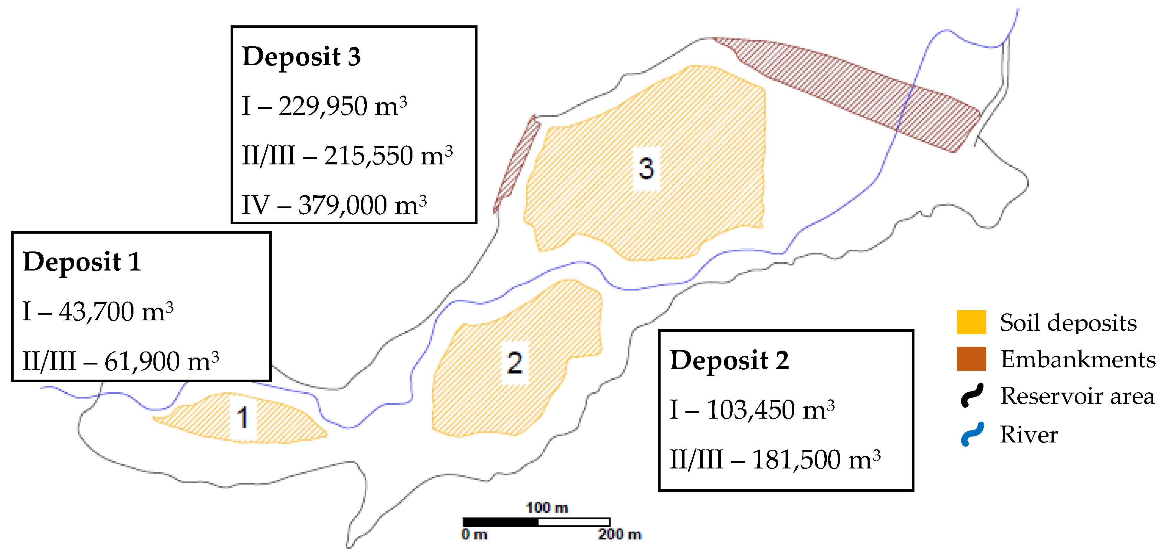
The Szalejów Górny dam body is formed using soil extracted from three deposits located within the reservoir basin. Deposit 1 is located in the area of the debris trap under construction. Deposit 2 is located in the central part of the reservoir on the right side of the Bystrzyca Dusznicka River. Deposit 3 is directly adjacent to the embankment. The location of the deposits is shown in Figure 1. The abundance of quaternary soils, i.e., fluvial and deluvial sediments that can be built into earth structures, was analysed. Then, based on this analysis, four layers in the deposits were identified (Table 2).
Category IV soil, i.e., clay and silty clay, is considered to meet the design assumptions and be suitable for direct build-up into the dam body if the proper moisture content is achieved. The same applies to Layer I, which has very similar characteristics and parameters as Category IV, subject to prior removal of the fraction exceeding 150 mm. Due to insufficient quantities of the material in the deposits, Layers II and III were also included. These layers have a stone fraction of 50–70% and thus require prior crushing.
2.3. Dam Body
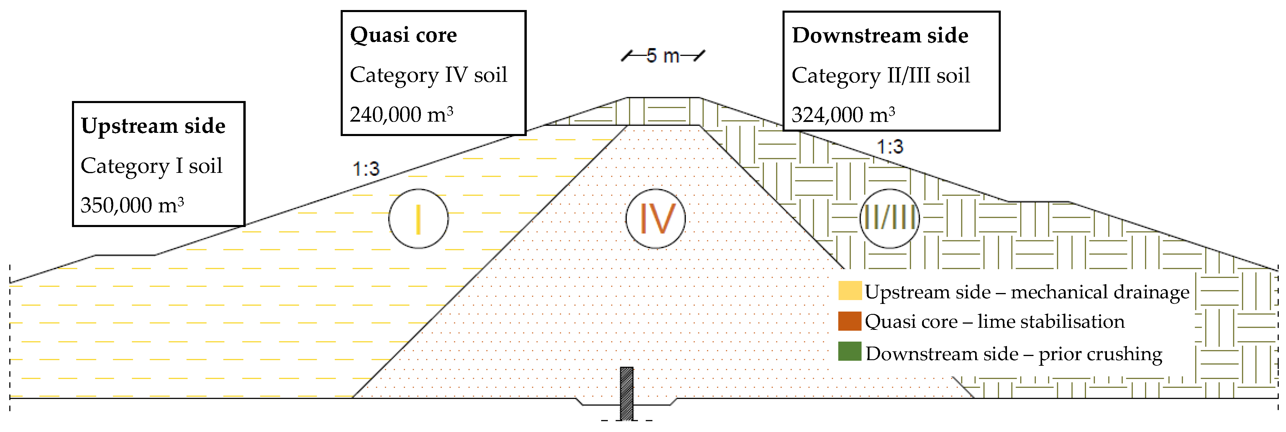
As the subsurface conditions were different from those assumed in geological engineering documentation, it was decided to deepen the foundation of the dam body at the initial stage of construction. This resulted in a significant increase in the volume of the structure and more intensive exploitation of deposits located in the reservoir basin. The proposed alternative design of Szalejów Górny assumes the body formation based on the following zones: the upstream side, the downstream side, and the central part referred to below as the quasi core. Cohesive soil cores in earth dams are used to seal the embankment and limit filtration flows [15,16,17]. However, this applies mainly to structures formed from non-cohesive soils. As low-permeability material is also used on the upstream side of the dam, the core function is not typical (hence the name “quasi”). Furthermore, it is not exposed to filtration flows in the case of incidental and short water damming in the reservoir. Due to the limited amount of a given type of material in the deposits in the reservoir basin area, soils with different parameters were used for the formation of each zone. In addition, a different drainage method was chosen to bring the material to optimum moisture content. For the quasi core, chemical drainage with slaked lime (hydrated lime, Ca(OH)2) or quicklime (CaO) was used. For the upstream side of the dam, it was decided to use only a method involving mechanical soil drainage by scarification. A schematic cross-section of the dam body is shown in Figure 2.
2.4. Moisture Content of the Soil in the Deposits vs. the Degree of Compaction of the Embankment
The compaction of the embankment is determined by the compaction index:
where:
- Is—compaction index [-]
- ϱds—bulk density of soil skeleton compacted in the embankment [t/m3]
- ϱd max—maximum bulk density of the soil skeleton compacted in the embankment obtained using the appropriate compaction method [t/m3]
The moisture content level at which the soil achieves the highest ϱd max is called the optimum moisture content. The use of the material with optimum moisture content to form the dam body results in the correct compaction index required for the structure (Table 3).
Soils compacted at a moisture content close to the optimum moisture content are also more resistant to frost and dampness. Cohesive soils compacted at a moisture content lower than the optimum moisture content reduce their bearing capacity in the event of dampness [21]. Therefore, it is necessary to monitor this parameter to try to achieve the most favourable values.
While loose soil deposits usually do not require any additional treatment, in the case of cohesive soils, the need to obtain the proper moisture content has to be taken into account [15,17]. Investigations of the material extracted from the deposits and intended to be built into the Szalejów Górny dam body (Table 4) have shown that the entire mass of soil is saturated with water above the level facilitating the achievement of proper compaction of the embankment layer and thus it is necessary to drain it.
2.5. Soil Drainage and Stabilisation
2.5.1. Mechanical Drainage
- Soil loosening from the deposit along an inclined surface crosses the entire thickness of the layer at a gradient that allows water to drain away.
- Soil dumping with the appropriate gradient of the embankment.
- Transport of the material to the drying site or directly to the dam body layer.
- Moving, loosening, and breaking up the soil to expose it to the sun and wind.
- Compacting smoothly with a gradient that allows water to run off during rainfall.
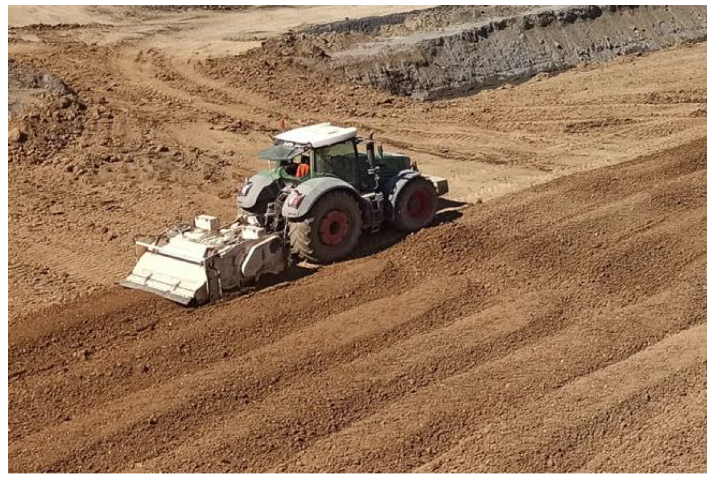
Due to the slow drying rate and the limited time available for the project, the number of passes of the soil loosening and grinding equipment was increased to intensify the process. To this end, the equipment with the greatest efficiency for the work performed was used, i.e., the MPH 600 recycler or a combination of the 261 kW stabiliser and tractor (Figure 3). The greatest efficiency was achieved when both types of machines worked together. On the first pass, the recycler was used to break up the soil to allow the stabiliser to work more effectively. However, the average number of passes needed to dry 1 m3 of Category I soil was more than seven times, which is highly unfavourable in economic terms. The rate of embankment formation does not counteract this trend because the technology is strongly influenced by weather conditions and there are days that prevent mechanical soil drainage.
2.5.2. Chemical Drainage—Lime Stabilisation
Lime stabilisation is possible mainly in cohesive soils as well as clayey gravels, sandy gravels, and sands [8]. Stabilisation is not recommended for soils with a plasticity index of less than 10 and more than 10% humic content (by weight). In the process analysed in this paper, the following types of lime were used:
- Slaked lime (hydrated lime, Ca(OH)2)—medium cohesive soils.
- Hydraulic lime (2CaOSiO2, CaOAl2O3)—low-cohesive soils, gravels, and sandy gravels with a lower plasticity index.
- Quicklime (CaO)—very cohesive soils and acidic soils with higher humic content.
Lime is mixed with the soil in an amount of 2 to 8% by weight of dry material and the dosage is determined on the basis of laboratory tests as defined by PN-S-96011 [44]. The optimum moisture content of the soil after stabilisation is increased by 10 to 20% (by weight of the admixtures used) for slaked or hydraulic lime and as much as 50% for quicklime. This is because quicklime (CaO) enters into a chemical reaction with water producing a large amount of heat and calcium hydroxide, i.e., the slaked lime (Ca(OH)2) [45,46,47].
This is an exothermic reaction resulting in additional water evaporation and allowing the soil to dry more quickly and efficiently, even at negative temperatures (down to −5 °C) [48].
This is followed by ion exchange between calcium hydroxide Ca2+ and OH− and the ions of clay minerals, which is the essence of the slaked-lime stabilisation. Ion exchange changes the liquid limit and plasticity of the soil making them favourable in terms of compactability and strength.
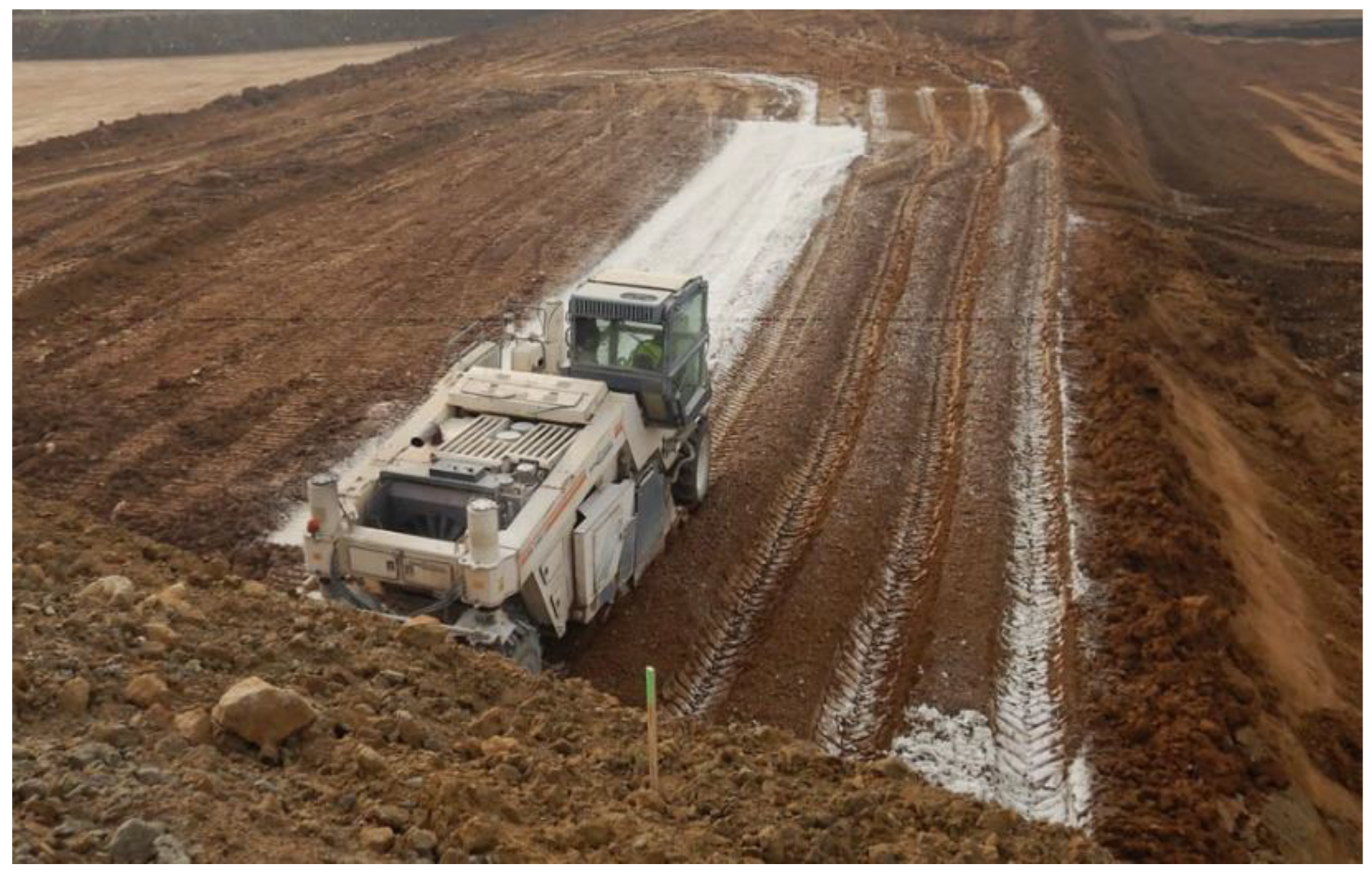
To stabilise Category IV soil used during the formation of the quasi core of the Szalejów Górny dam, slaked lime (hydrated lime, Ca(OH)2) or, in particular, quicklime (CaO) was used according to PN-EN 459-1 [49] in amounts depending on the location and moisture content of the material. Table 5 summarises the typical chemical characteristics of quicklime as a building material based on the declaration of performance. Soil grinding and loosening (to mix the soil with the binder) was carried out using the MPH 600 recycler (Figure 4).
3. Results
As described in the previous section, different zones of the dam body use soils with different parameters and different drainage technologies. For the quasi core, Category IV soil, chemically dried by lime stabilisation, was used. For the upstream side, the soil previously described as Category I, subject only to mechanical drainage, was used, due to the lack of widespread research that could confirm the validity of lime-drained soils for zones exposed to permanent or periodic contact with water. For the downstream side, for economic reasons i.e., the high cost of crushing the available material, as well as its high natural moisture content, part of the Category II-III soil was replaced with aggregate with a 0/20 mm fraction supplied from the mine.
3.1. Mechanical Drainage
The average temperatures and precipitation over the construction season as well as the efficiency of the body formation with mechanically drained Category I soils are shown in Figure 5 and Figure 6 respectively.
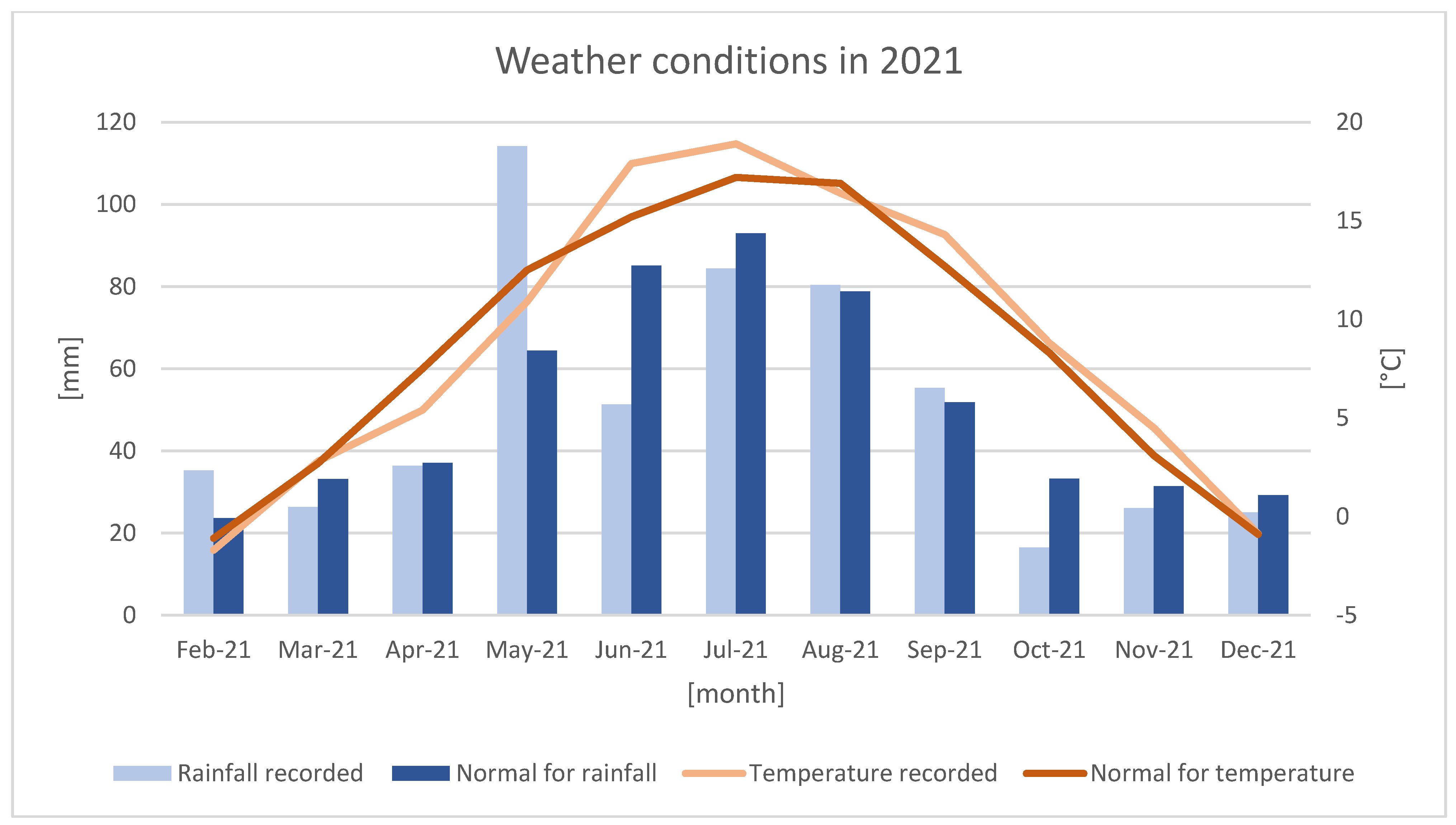
In 2021, in the area of Szalejów Górny, temperatures were lower than normal values as reported by the Institute of Meteorology and Water Management—National Research Institute [51] at the beginning of spring and higher during the calendar summer. In May, particularly intense precipitation was observed. In June, it was lower than normal. Overall, the weather conditions in 2021 did not differ significantly from the normal in the region. The spring period, which was not conducive to mechanical soil drainage, was the exception.
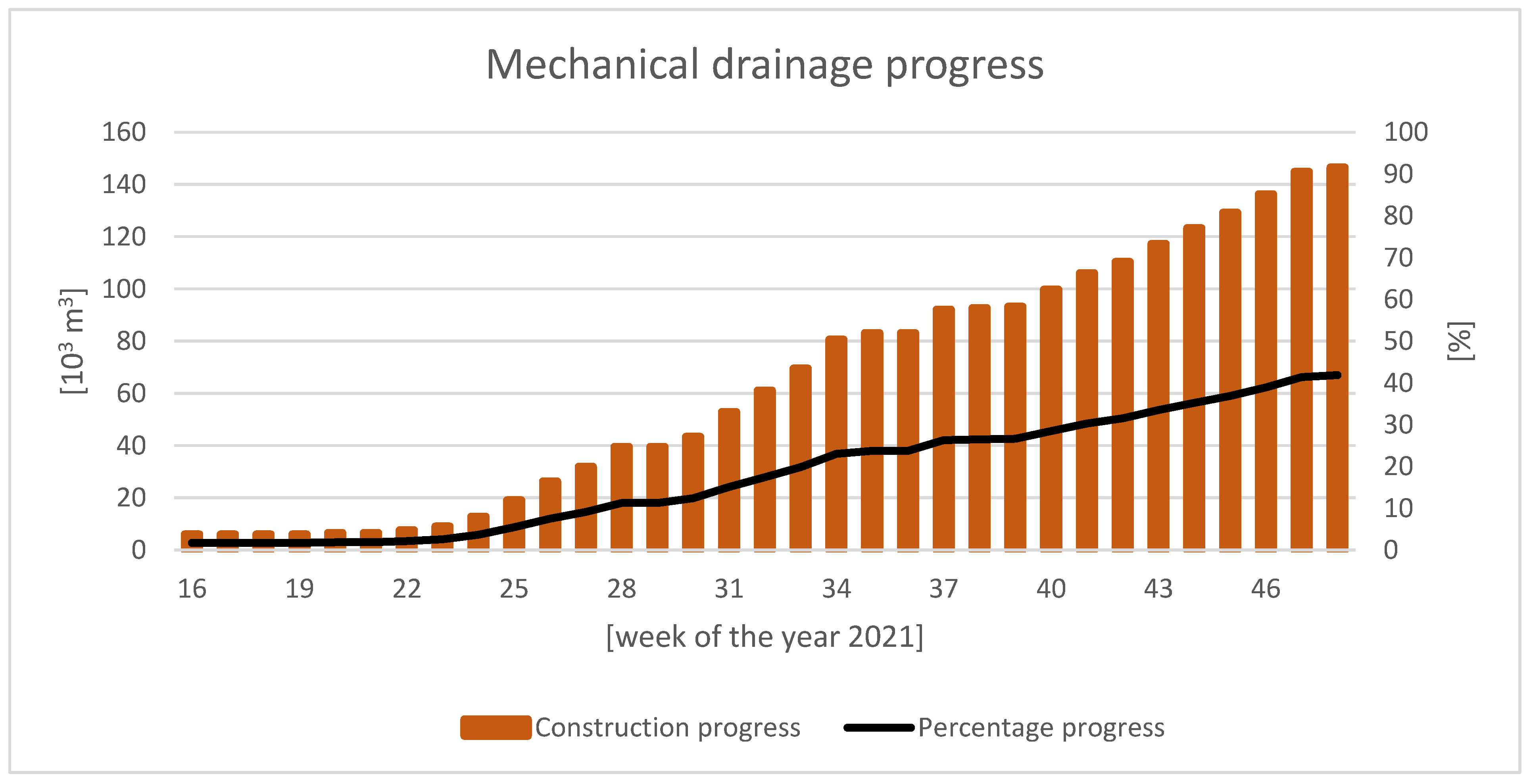
The formation of the upstream side of the Szalejów Górny dam body with mechanically drained Category I soils started to progress only in June. This coincides with the weather conditions indicated in Chart 1. There were occasional breaks in the process and its intensity varied. The process stopped at the beginning of December. The achieved volume was 146,000 m3, accounting for approximately 42% of the embankment for the upstream side. Therefore, the assumptions made might not be met (the entire process might end within two construction seasons).
3.2. Chemical Drainage—Lime Stabilisation
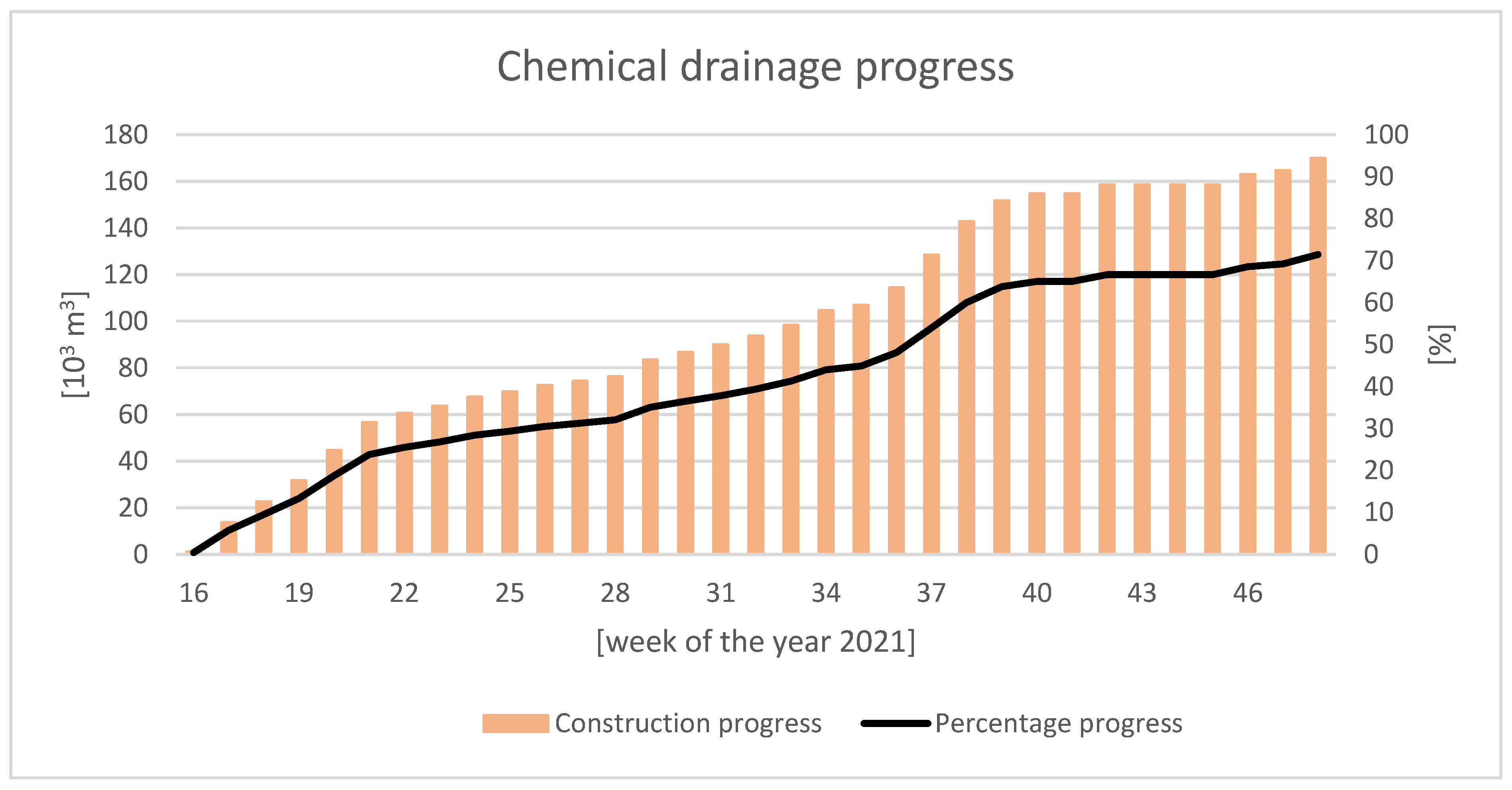
The progress of the stabilisation of Category IV soil by chemical drainage is shown in Figure 7.
The construction of the quasi core of the Szalejów Górny dam body with Category IV lime-stabilised soils started with great intensity at the very beginning of the construction season. The stoppages and slowdowns occurred because the quasi core was formed too quickly and was excessively high in relation to the outer zones. By the end of the year, the achieved volume was 170,000 m3, accounting for approximately 71% of the quasi core embankment. Had it not been for the limited works site caused by the excessive height difference, as referred to above, it would have been possible to complete this part of the work within one construction season.
3.3. Comparison of the Two Soil Drainage Technologies
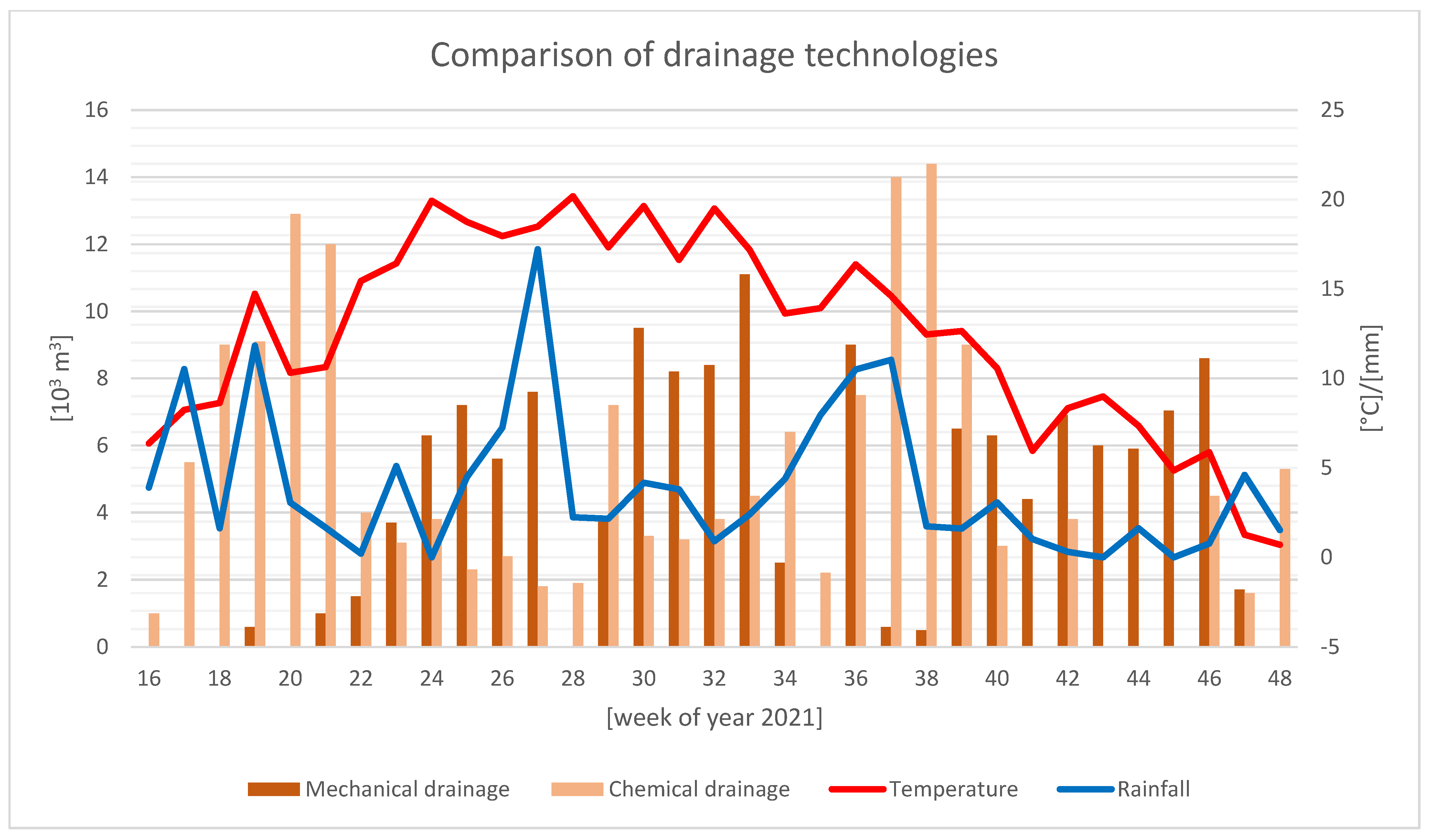
Figure 8 shows the efficiencies of mechanical and chemical drainage for each period in 2021 as well as the averaged daily temperatures and precipitation for each week.
The chart is a good illustration of how the intensity of mechanical soil drainage coincides with weather conditions. The increased precipitation occurred prior to the period in which the progress of mechanical drainage was low or non-existent. During spring, when average daily temperatures were below 15 °C and frequent rains occurred, it was not possible to start the work. The highest efficiency of the technology was achieved in weeks 30 to 33 with the progress of up to approx. 11,000 m3/week. This coincides with a period of very favourable weather conditions. Obtaining a capacity greater than 10,000 m3/week occurred once during the entire construction season.
In contrast to mechanical drainage, the efficiency of lime stabilisation is less dependent on temperature or precipitation. Interestingly enough, it reached particularly high values (approx. 14,000 m3/week) during the periods at which mechanical drainage was not possible. Obtaining a capacity greater than 10,000 m3/week occurred four times throughout the construction season. The periodically lower intensity was due to the excessive height in relation to the outer zones of the body as described above.
3.4. Parameters of the Soil Built into the Szalejów Górny Dam Body
Table 6 shows the basic strength parameters of compacted soils of Categories I and IV built into the upstream side and the quasi core of the Szalejów Górny dam body. Due to the relative variability of the parameters, the table shows extreme and average values. The material analysis involves the following parameters:
- Hydraulic conductivity—the ability of the soil to transmit water, expressed by the distance travelled by the fluid in the soil in one second.
- Degree of plasticity—the state of the soil between the compact state (IL < 0) and the liquid state (IL > 1).
- Plasticity index—the amount of water a soil absorbs when changing from a semi-compact to a liquid state; defines the state of the material in a range from loose material (Ip < 1%) to very cohesive material (Ip > 30%).
- Angle of repose—a parameter depending, among others, on the granulometric composition and degree of compaction, describing the shear strength, i.e., the resistance that the soil gives to shear stress at the point in the medium.
- Cohesion—the internal pressure resulting from the mutual attraction between soil particles balanced by repulsive forces, correlated with the number of particles per unit volume of the soil and describing its resistance to deformation.
Despite high variability, the strength parameters corresponding to the material properties in Table 6 are favourably high. This is particularly the case for the angle of repose and the cohesion of the soils of both categories. In addition, the strength parameters prove a positive impact of this technology as significantly lower values for the degree of plasticity was found as a result of the use of lime as the stabilised material. The soils of both categories, especially the material built into the upstream side, have low hydraulic conductivity values. This means that water will not be able to penetrate deep into the dam and reach the quasi core in the case of periodic damming typical of a dry reservoir. Based on the tests reported in [31], it can be assumed that the higher hydraulic conductivity obtained for Category IV soil was due to the overestimation of the lime dose and excessive drying of the material. Notwithstanding the above, hydraulic conductivity values are favourable to the hydraulic engineering structure under construction. It was also confirmed that the cohesion of stabilised soil measurably increases compared to the soil subject to mechanical drainage.
4. Discussion and Conclusions
4.1. Overview of Soil Testing
This section presents the research reported in available sources and scientific publications. From the point of view of hydraulic engineering structure, it is particularly necessary to assess the influence of compaction and rehydration on the basic soil parameters and the significance of the leaching of lime particles out of the stabilised material under the influence of water filtration.
4.1.1. The Effect of Changes in Moisture Content and Filtration on Lime-Stabilised Soil
When investigating the durability of lime-stabilised soil, it is necessary to assess the influence of binder leachability on material characteristics [53,54]. The literature and certain scientific publications addressing stabilised soils analyse the influence of water filtration on the leaching of lime particles out of the stabilised material.
In this respect, the data provided in the article entitled, “Clay mineralogy effects on the long-term performance of chemically treated expansive clays”, by Bhaskar C. S. Chittoori, are of relevance to this paper [25]. The author presents the results of a number of studies examining the effects of changes in moisture and water flow on stabilised soil. In the article entitled, “The impact of cyclic wetting and drying on the swelling behaviour of stabilised expansive soils”, by S. Rao et al. [23], clay soils stabilised with cement or lime are subjected to cyclic drying and rehydration, resulting in a partial loss of lime benefits. Article entitled, “Extending durability of lime modified clay subgrades with cement stabilisation”, by A. B. Marshall and P. A. Frank [24], reaches a different conclusion, indicating that liming the soil increased its resistance to strength degradation during frequent drainage and irrigation.
Article entitled, “Shear strength and elastic properties of lime-soil mixtures”, by M. S. Thompson [26], addresses the issue of stabiliser leaching, noting that the filtering water has a direct impact on unfavourable lime-to-magnesium ratio and that the pH of the stabilised material changes, resulting in water permeability of the sample (soil with a lower hydraulic conductivity is exposed to smaller parameter variations). The article entitled, “Evaluation of remoulded field samples of lime-cement-fly ash-aggregate mixture”, by E. J. Barenberg [27], describes a study of soil compacted at optimum moisture content. The stabilised material is exposed to flowing water for 10 days. The subsequent chemical analysis of the samples shows that only small amounts of the stabiliser leached out.
In [25] cited above, a study of soil samples subjected to fourteen water leaching cycles of 24 h each is presented. In particular, changes in pH are analysed and significant observations are made with regard to the significant reduction of the concentration of lime particles in the material (from 610 ppm to 310 ppm after all cycles). However, the soil subjected to leaching (classified as highly compressible clay) was not additionally compacted and had a porosity coefficient of e = 0.856. A similar study is reported in an article entitled, “Leachate studies on lime and portland cement treated expansive clays”, by S. Chittoori [28], concluding that the loss of soil strength is not significantly correlated with the loss of stabiliser.
4.1.2. Change in Soil Parameters after Stabilisation and Compaction
The analysis of the change in strength parameters of soil compacted in the embankment of a dam or dike body, also under the influence of rehydration [29,30], is crucial for the further development of lime stabilisation technology in the field of hydraulic engineering structures. The SOTREDI project entitled, “SOil TREatment for Dikes”, carried out by Belgian and French research units, is an important contribution to this area of research. Article entitled, “Lime treatment: new perspectives for the use of silty and clayey soils in earthen hydraulic structures” [31] analyses whether soils subjected to stabilisation can meet the high requirements for damming structures. To this end, experimental dikes were constructed to confirm the results of laboratory tests with respect to parameters, such as water permeability, mechanical stability, and erosion resistance. The authors challenge the assumption that the use of lime has an adverse effect on hydraulic conductivity, increasing its value. They show that chemical stabilisation has a much smaller effect on water permeability than material moisture content and compaction method. For limed silty clay samples, k < 5 × 10⁻⁹ was achieved. The bearing capacity of the stabilised soil was determined based on the values of the angle of repose and cohesion. While the value of the former did not change significantly after the addition of lime, the latter increased by more than twenty-five times after two years after the use of the stabilisation method in one case reaching 500 kPa. Note that a significant increase in this parameter was observed after the first three days, which means that the material was almost incompressible and deformation-free. The crumb test using a sample of the material in distilled water revealed that the initially dispersed lime-stabilised soil did not undergo significant dispersion for 45 h after immersion in the solvent as compared to 15 min for non-stabilised material. The Hole Erosion Test (HET) was used to determine the soil resistance to internal erosion. Its results show that the erosion threshold value for the untreated clay soil corresponds to a water velocity of 2 m/s as compared to 10 m/s for the lime-treated material. A Mobile Jets Erosion Test (MoJET) was also carried out to assess surface erosion. The surface of a soil sample was subjected to six rotating streams of water and leached particles were collected and weighed. It was not possible to initiate erosion for the lime-stabilised silty soil after ninety days, even with a significant increase in flow.
4.2. Discussion
The results presented in this paper leave no doubt as to which drainage technology for cohesive soils provides higher efficiency and is independent of weather conditions. The only question that can be raised is whether liming is economically viable given the need to purchase a binder and provide specialised equipment to carry out the stabilisation. However, it should be noted that the project implementation model that is currently in force always entails additional costs due to the extended completion period. In the case of structures with significant volumes, such as dams for water reservoirs, and given the need to carry out earthworks at the right pace, it is not in the Investor’s interest to run the risk of exceeding the deadlines. In this respect, adopting an efficient and reliable technology should be a priority at the planning stage.
Earthen hydraulic engineering structures, formed using lime stabilisation, are developed in various countries, especially in the United States, but also in Germany and France. Mention should be made of the Friant-Kern Canal in California experiencing the erosion of embankments at and below the water table. Reclamation work was carried out between 1973 and 1977 using burnt lime at a rate of 4%. After almost 50 years of continuous contact with water, traces of erosion are negligible and maintenance activities are very limited [31,33,34]. Another example is the dikes on the Mississippi River damaged by the 1973 flood. The use of lime allowed more than 150 landslides to be repaired without the need to demolish the damaged structures and transport soil to rebuild them [35]. The European hydraulic engineering structures using lime stabilisation include the dry flood reservoirs in Rems, Langenneufnach, Engelshofer Bach, and Merching in Germany. The environmental impact of soil liming should also be assessed. In [55], it is suggested that the chemical reactions occurring in the stabilised material are harmful. However, studies described in the literature [25,31,56] have not shown ecotoxicity as a result of the use of lime-stabilised soil. The increased rate of project implementation is indirectly due to the attempt to avoid potential environmental damage resulting from the sensitivity of the construction process (i.e., its general negative influence on the ecosystem of the area).
Despite the gradually increasing number of hydraulic engineering projects based on liming, there is still a noticeable reluctance to use stabilised soil. The construction of the Szalejów Górny dam body is an example of this trend. Liming of the soil built into the upstream side would undoubtedly allow the deadlines to be met and would be more economically viable due to the low efficiency of mechanical drainage, even at the high intensification of the process. In addition, an approach that seeks to limit any contact between the stabilised soil and the water contradicts the Friant-Kern Canal experience described above. In addition, the fear of lime particles leaching out of the compacted soil was questioned [27]. It was pointed out that this has little effect on the strength of the material [28]. On the basis of the previously cited studies, [31] explicitly suggests the use of the stabilised material on the outer and most exposed parts of flood embankments due to its high erosion resistance.
Soil stabilisation with lime hinders material homogeneity. However, it is clear that this is a global problem exceeding beyond the stabilised material as far as the formation of hydraulic engineering embankments is concerned. This is evidenced by the testing of the Category I soil built into the upstream side as the values of its strength parameters correspond well with the limed quasi core. Given the above, rather than ceasing chemical drainage, it should be assessed if it is possible to alternate layers of stabilised soil with unmodified material. Ostensibly, this could indicate the heterogeneity of the embankment. However, in practice, it would avoid local drying resulting in decreased hydraulic conductivity in the respective layers.
Based on the study under this paper, it can be concluded that the technology of cohesive soil stabilisation with lime is not only an optimal solution for the construction of dry reservoir dams and dikes but also suitable for structures causing permanent water damming. The latter would require a comprehensive study of the soil to be built into the dam body at the stage of planning and drawing up the geological engineering documentation prior to the commencement of the project, including the selection of the appropriate lime dosage and assessing the effect of permanent filling of the pores with water on the basic strength parameters. However, these steps would be justified by eliminating the risk of exceeding the completion dates and increasing the project-related costs.
4.3. Conclusions
On the basis of the conducted tests and observations, a high efficiency of dam body formation from lime-drained soil was found, which reached a maximum of approx. 14,000 m3/week, and values exceeding 10,000 m3/week were obtained four times during the entire construction season of the year 2021. Despite the intensification of mechanical drainage by increasing the number of passes with soil loosening equipment—for this technology it was not possible to obtain such a high efficiency of material installation as was achieved in the case of its stabilisation with lime. This was also true during periods of favourable weather conditions, during which a maximum output of approx. 11,000 m3/week was achieved, which was the only incident of exceeding the value of 10,000 m3/week. It should be emphasised that when low temperatures or rainfall prevented the natural drying of the soil, the application of lime allowed the earthworks to continue uninterrupted. Tests on samples of the soil built into the dam body showed significant changes in some strength parameters, influenced by the application of lime stabilisation. These changes should be considered positive, particularly with regard to the angle of internal friction, cohesion and degree of plasticity. Slightly higher values of the filtration coefficient were also observed, which could potentially have been influenced by the overestimation of the lime dosage. The results obtained indicate a significant advantage of lime stabilisation in the case of cohesive soil drainage, which translates into a higher work rate and greater independence from weather conditions. This technology, when used rationally and when the correct dose is selected, makes it possible to obtain improved values of soil strength parameters, which gives grounds for its more frequent application also during the formation of hydrotechnical embankments with the function of the water damming.
Author Contributions
Conceptualisation, M.P. and M.W.; Methodology, M.P.; Software, M.P.; Validation, M.W.; Formal analysis, M.P.; Investigation, M.P. and M.W.; Resources, M.P.; Data curation, M.P.; Writing—original draft preparation, M.P.; Writing—review and editing, M.P. and M.W.; Visualisation, M.P.; Supervision, M.W.; Project administration, M.P.; Funding acquisition, M.P. and M.W. All authors have read and agreed to the published version of the manuscript.
Funding
Financed by the Wrocław University of Environmental and Life Sciences.
Institutional Review Board Statement
Not applicable.
Informed Consent Statement
Not applicable.
Data Availability Statement
Not applicable.
Acknowledgments
The authors would like to express their thanks to the Power Construction Corporation of China, the GHEKO Geotechnical Research Laboratory, the PROXIMA Geological Company, and the Institute of Meteorology and Water Management for providing the data and research results used in the article. The article was presented at the 5th Scientific and Technical Conference Exploitation and Impact of Water Reservoirs, Mikorzyn-Jeziorsko 2022, Poland.
Conflicts of Interest
The authors declare no conflict of interest.
References
- Wu, Z.; Peng, Y.; Li, Z.; Li, B.; Yu, H.; Zheng, S. Commentary of research situation and innovation frontier in hydro-structure engineering science. Sci. China Technol. Sci. 2011, 54, 767–780. [Google Scholar] [CrossRef]
- Kundzewicz, Z.; Zaleski, J.; Nachlik, E. Managing water—Challenges for Poland. Nauka 2021, 1, 79–102. [Google Scholar] [CrossRef]
- Winter, J.A.; Wita, A.; Popielski, P.; Sieinski, E. Damming Structures—Operation and Monitoring; Monographs of the Institute of Meteorology and Water Management; Institute of Meteorology and Water Management: Warszawa, Poland, 2017; Available online: https://repo.pw.edu.pl/info/book/WUTcb39674b209442e78b478eef6ee4c645/ (accessed on 21 September 2022).
- Kledyński, Z.; Krysiak, Ł. Dam safety—Comparative study of normative documents. Acta Sci. Pol. Archit. 2017, 16, 89–96. [Google Scholar] [CrossRef]
- Nowak, B.; Lawniczak-Malińska, A.E. The Influence of Hydrometeorological Conditions on Changes in Littoral and Riparian Vegetation of a Meromictic Lake in the Last Half-Century. Water 2019, 11, 2651. [Google Scholar] [CrossRef] [Green Version]
- Ptak, M.; Sojka, M.; Choiński, A.; Nowak, B. Effect of Environmental Conditions and Morphometric Parameters on Surface Water Temperature in Polish Lakes. Water 2018, 10, 580. [Google Scholar] [CrossRef] [Green Version]
- Myronidis, D.; Ioannou, K. Forecasting the Urban Expansion Effects on the Design Storm Hydrograph and Sediment Yield Using Artificial Neural Networks. Water 2019, 11, 31. [Google Scholar] [CrossRef] [Green Version]
- Falaciński, P. Retention and management of rainwater in urbanized areas as goals of sustainable development. In Safety of Hydrotechnical Structures; Winter, J.A., Andrzej, W., Paweł, P., Sieinski, E., Eds.; Institute of Meteorology and Water Management—National Research Institute: Warszawa, Poland, 2021; pp. 131–141. ISBN 978-83-64979-41-5. Available online: https://repo.pw.edu.pl/info/article/WUT8a10d5e4455a4676935b3573807e929d/ (accessed on 21 September 2022).
- Liu, L.; Sun, J.; Lin, B.; Lu, L. Building performance in dam-break flow—An experimental study. Urban Water J. 2018, 15, 251–258. [Google Scholar] [CrossRef]
- Banzhaf, P. Rehabilitation of aging embankment dams. In Safety of Hydrotechnical Structures; Winter, J.A., Wita, A., Popielski, P., Sieinski, E., Eds.; Institute of Meteorology and Water Management—National Research Institute: Warszawa, Poland, 2021; pp. 31–43. ISBN 978-83-64979-41-5. Available online: https://repo.pw.edu.pl/info/book/WUTabfe52df4fe54f668e383b3b0558f4a8/ (accessed on 21 September 2022).
- Zedan, A.J.; Faris, M.R.; Abdulsattar, A.A. Seepage Analysis through an Earth Dam (KHASA-CHAI Dam) as a Case Study. Eng. Technol. J. 2017, 35, 172–181. [Google Scholar]
- Mavlyanov, N.G.; Abdullaev, S.K. Monitoring of building the dam of Rezaksay water storage from the point of view of engineering geology. In Proceedings of the 17th International Conference on Soil Mechanics and Geotechnical Engineering, Alexandria, Egypt, 5–9 October 2009. [Google Scholar] [CrossRef]
- Maślanka, K.; Kostuch, R. Świnna Poręba—Long Awaited Water Reservoir. Acta Sci. Pol. Form. Circumiectus 2015, 14, 161–168. [Google Scholar] [CrossRef]
- Kokoszka, R.; Zawisza, E. Guidelines for water management of Świnna Poręba reservoir in the aspect of its main functions. Infrastruct. Ekol. Rural. Areas 2008, 5, 139–147. [Google Scholar]
- Czyżewski, K. Earth Dams; Arkady: Warsaw, Poland, 1973. (In Polish) [Google Scholar]
- US Army Corps of Engineers. General Design and Construction Considerations for Earth and Rock-Fill Dams; EM 1110-2-2300; US Army Corps of Engineers: Washington, DC, USA, 2004. [Google Scholar]
- U.S. Department of the Interior Bureau of Reclamation. Earth Manual Part I; Earth Sciences and Research Laboratory Geotechnical Research Technical Service Center: Denver, CO, USA, 1998.
- Wiatkowski, M.; Rosik-Dulewska, C. Water management problems at the Bukówka drinking water reservoir’s cross-border basin area in terms of its established functions. J. Ecol. Eng. 2015, 16, 52–60. [Google Scholar] [CrossRef]
- Wiatkowski, M. Problems of water management in the reservoir Młyny located on the Julianpolka river. Acta Sci. Pol. Form. Circumiectus 2015, 14, 191–203. [Google Scholar] [CrossRef]
- Wiatkowski, M.; Wiatkowska, B.; Gruss, Ł.; Rosik-Dulewska, C.; Tomczyk, P.; Chłopek, D. Assessment of the possibility of implementing small retention reservoirs in terms of the need to increase water resources. Arch. Environ. Prot. 2021, 47, 80–100. [Google Scholar] [CrossRef]
- Wiłun, Z. Outline of Geotechnics; WKiŁ: Warsaw, Poland, 1987. (In Polish) [Google Scholar]
- Pawar, R.V.; Dhumal, S.V.; Minigi, G.M.; Waghule, A.; Navkar, Y. Review On Soil Stabilization Technique. Int. Res. J. Eng. Technol. (IRJET) 2019, 6, 2211–2214. [Google Scholar]
- Rao, S.M.; Reddy, B.V.V.; Muttharam, M. The impact of cyclic wetting and drying on the swelling behavior of stabilized expansive soils. Eng. Geol. 2001, 60, 223–233. [Google Scholar] [CrossRef]
- Addison, M.B.; Polma, F.A. Extending durability of lime modified clay subgrades with cement stabilization. In Proceedings of the Sessions of Geo-Denver Soil Improvement, Denver, CO, USA, 18–21 February 2007; pp. 1–10. Available online: https://ascelibrary.org/doi/10.1061/40916%28235%297 (accessed on 21 September 2022).
- Chittoori, B.C.S. Clay Mineralogy Effects on Long-Term Performance of Chemically Treated Expansive Clays; The University of Texas At Arlington: Arlington, TX, USA, 2009; Available online: http://hdl.handle.net/10106/1809 (accessed on 21 September 2022).
- Thompson, M.S. Shear Strength and Elastic Properties of Lime-Soil Mixtures; University of Illinois: Urbana, IL, USA, 1966; Available online: https://onlinepubs.trb.org/Onlinepubs/hrr/1966/139/139-001.pdf (accessed on 21 September 2022).
- Barenberg, E.J. Evaluation of Remolded Field Samples of Lime-Cement-Fly Ash-Aggregate Mixture; Highway Research Record No. 315; Highway Research Board: Washington, DC, USA, 1970; pp. 112–121. Available online: https://onlinepubs.trb.org/Onlinepubs/hrr/1970/315/315-010.pdf (accessed on 21 September 2022).
- Chittoori, S.; Pedarla, A.; Puppala A., J.; Hoyos L., R.; Nazarian, S.; Saride, S. Leachate Studies on Lime and Portland Cement Treated Expansive Clays. In Proceedings of the Geo-Frontiers Congress 2011, Dallas, TX, USA, 13–16 March 2011. [Google Scholar] [CrossRef]
- Okeke, C.; Johnson, A.; Ogbuagu, F.U.; Akinmusuru, J.O. Effects of continuous leaching on engineering properties of lime-stabilized lateritic soils. IOP Conf. Ser. Mater. Sci. Eng. 2019, 640, 012084. Available online: https://iopscience.iop.org/article/10.1088/1757-899X/640/1/012084 (accessed on 21 September 2022). [CrossRef] [Green Version]
- Okeke, C.; Abbey, S.; Oti, J.; Eyo, E.; Johnson, A.; Ngambi, S.; Abam, T.; Ujile, M. Appropriate Use of Lime in the Study of the Physicochemical Behaviour of Stabilised Lateritic Soil under Continuous Water Ingress. Sustainability 2021, 13, 257. [Google Scholar] [CrossRef]
- Herrier, G.; Puiatti, D.; Chevalier, C.; Froumentin, M.; Bonelli, S.; Fry, J.J. Lime Treatment: New Perspectives for the use of Silty and Clayey Soils in Earthen Hydraulic Structures. In Proceedings of the 9th ICOLD European Club Symposium, Venise, Italy, 10–12 April 2017; p. 10. Available online: https://hal.archives-ouvertes.fr/hal-01548437 (accessed on 21 September 2022).
- Herrier, G.; Campos, G.; Nerincx, N.; Puiatti, D.; Tachker, P.; Cornacchioli, F.; Bonelli, S. Lime treatment of soils: A solution for erosion-resistant hydraulic earthen structures. In Proceedings of the Dam World 2018, 3rd International Dam World Conference, Foz di Iguaçu, Brazil, 17–21 September 2018. [Google Scholar]
- Knodel, P.C. Lime in Canal and Dam Stabilization; Report No GR-87-10; US Bureau of Reclamation: Denver, CO, USA, 1987; 21p.
- Howard, A.K.; Bara, J.P. Lime Stabilization on Friant-Kern Canal; Report No. REC-ERC-76-20; U.S. Bureau of Reclamation: Denver, CO, USA, 1976; 61p.
- Fleming, R.; Sills, G.; Stewart, E. Lime Stabilization of Levee Slopes. In Proceedings of the Second Interagency Symposium on Stabilization of Soils and Other Materials, Metairie, LA, USA, 3–5 November 1992. [Google Scholar]
- The Odra-Vistula Flood Management Project. Available online: https://odrapcu.pl/en/project-ovfmp/about-project-ovfmp/ (accessed on 21 September 2022).
- Lenar-Matyas, A.; Poulard, C.; Ratomski, J.; Royer, P. The construction and action of dry dams with the different characteristics and location. Infrastruct. Ecol. Rural. Areas 2009, 9, 115–129. [Google Scholar]
- Łapuszek, M.; Witkowska, H. Dynamic slow down in the mountainous catchment. Infrastruct. Ecol. Rural. Areas 2005, 4, 71–84. [Google Scholar]
- Lenar-Matyas, A.; Lapuszek, M.; Poulard, C.; Royet, P. The study on dry dams efficiency during the flood events: The analysis of selected dry dams in France. Infrastruct. Ecol. Rural. Areas 2009, 9, 143–154. [Google Scholar]
- Kałuża, T.; Zawadzki, P.; Mądrawski, J.; Stasik, R. Analysis of impact of Strużyna reservoir modernization on groundwater level. Acta Sci. Pol. Form. Circumiectus 2017, 16, 153–169. [Google Scholar] [CrossRef] [Green Version]
- Połomski, M. Role of the Szalejów Górny flood control dry reservoir on the Bystrzyca Dusznicka River with particular regard to its ability to reduce flood waves. Water Manag. 2022, 6, 24–30. [Google Scholar] [CrossRef]
- Hawrysz, M.; Stróżyk, J.; Hawrysz, P. Opinion on the Abundance of Deposits of Soil Material for the Formation of Earth Structures in the Area of the Szalejów Górny Flood Control Reservoir; GHEKO Design Studio: Wroclaw, Poland, 2019. [Google Scholar]
- Power Construction Corporation of China. Material Quality Certificate; Test Report No. K/2A.2/1/20/07/14 Provided by Power Construction Corporation of China; Power Construction Corporation of China: Beijing, China, 2020. [Google Scholar]
- Polish Standard PN-S-96011; 1998 Motor Roads—Stabilization of Soils with Lime for Road Purposes. The Polish Committee for Standardization: Warsaw, Poland, 1998.
- Barman, D.; Dash, S.K. Stabilization of expansive soils using chemical additives. A review. J. Rock Mech. Geotech. Eng. 2022, 14, 1319–1342. [Google Scholar] [CrossRef]
- Amadi, A.A.; Okeiyi, A. Use of quick and hydrated lime in stabilization of lateritic soil: Comparative analysis of laboratory data. Int. J. Geo-Eng. 2017, 8, 3. [Google Scholar] [CrossRef]
- Thompson, M.R. Lime Stabilization of Soils for Highway Purposes, Final Summary Rep. Civil Engineering Studies; Highway Series No. 25; Illinois Cooperative Highway Research Program; Project IHR-76; Ill Univ Hwy Res Lab Civil Eng Studies. 1968, p. 26. Available online: https://trid.trb.org/view/122693 (accessed on 21 September 2022).
- Kraszewski, C.; Dreger, M.; Mitrut, M.; Przygoda, M. Soil stabilization with quicklime in road engineering—Theory and practice. Mar. Eng. Geotech. 2020, 2, 82–86. [Google Scholar]
- Polish Standard PN-EN 459-1; 2015-06: Building Lime—Part 1: Definitions, Requirements and Conformity Criteria. The Polish Committee for Standardization: Warsaw, Poland, 2015.
- Power Construction Corporation of China. Declaration of Technical Performance No. 0355 “Burnt Building Lime EN 459-1 CL 90-Q (Rsv, Psv)”; Power Construction Corporation of China: Beijing, China, 2021. [Google Scholar]
- Institute of Meteorology and Water Management. Meteorological Statement for the Year 2021, Representative Data for the Area of the Town of Upper Szlajów, Klodzko Municipality, Lower Silesia Province, Poland; Institute of Meteorology and Water Management: Warsaw, Poland, 2021. [Google Scholar]
- Geological Company in Wroclaw PROXIMA S.A. Report on Research of Soil Embedded in the Dam Body of Szalejów Górny Reservoir; Laboratory of Chemical Research, Environmental Protection, Soil Mechanics, Aggregates and Rocks: Wrocław, Poland, 2021. [Google Scholar]
- Ulugonul, Y.O. Effect of Leaching on the Strength Properties of a Hydrated Lime-Cement Stabilized Soil. Master’s Thesis, Missouri University of Science and Technology, Rolla, MO, USA, 1960. Available online: https://scholarsmine.mst.edu/masters_theses/2794 (accessed on 21 September 2022).
- McCallister, L.D. The Effects of Leaching on Lime-Treated Expansive Clays; The University of Texas at Arlington: Arlington, TX, USA, 1990. [Google Scholar]
- Jawad, I.T.; Taha, M.R.; Majeed, Z.H.; Khan, T.A. Soil Stabilization Using Lime: Advantages, Disadvantages and Proposing aPotential Alternative. Res. J. Appl. Sci. Eng. Technol. 2014, 8, 510–520. [Google Scholar] [CrossRef]
- Bhengu, P.H.; Allopi, D. Influence of Lime on Lime Soil Stabilization on Natural Occurring Acidic Soil Engineering Properties. Am. Sci. Res. J. Eng. Technol. Sci. (ASRJETS) 2017, 30, 57–69. [Google Scholar]
Figure 1.
Location of soil deposits within the reservoir basin (internal analysis based on [42]).
Figure 1.
Location of soil deposits within the reservoir basin (internal analysis based on [42]).

Figure 2.
Characteristic cross-section of the dam body (internal analysis).

Figure 3.
Mechanical drainage. A combination of stabiliser and tractor (photo: Michal Bernacki).

Figure 4.
Lime stabilisation. MPH 600 recycler (photo: Michal Bernacki).

Figure 5.
Average monthly temperatures and precipitation in the area of Szalejów Górny in 2021 as compared to the normal [51].
Figure 5.
Average monthly temperatures and precipitation in the area of Szalejów Górny in 2021 as compared to the normal [51].

Figure 6.
Construction and percentage progress of mechanical drainage of Category I soil (internal analysis based on reports of the project contractor).
Figure 6.
Construction and percentage progress of mechanical drainage of Category I soil (internal analysis based on reports of the project contractor).

Figure 7.
Construction and percentage progress of the stabilisation of Category IV soil (internal analysis based on reports of the project contractor).
Figure 7.
Construction and percentage progress of the stabilisation of Category IV soil (internal analysis based on reports of the project contractor).

Figure 8.
The efficiencies of the analysed soil drainage technologies as well as average daily temperatures and precipitation (internal analysis based on reports of the project contractor and [51]).
Figure 8.
The efficiencies of the analysed soil drainage technologies as well as average daily temperatures and precipitation (internal analysis based on reports of the project contractor and [51]).


Table 1.
Basic parameters of Szalejów Górny [41].
Table 1.
Basic parameters of Szalejów Górny [41].
| Technical Characteristics | |
|---|---|
| Dam length | 735 m |
| Dam volume | 914,000 m3 |
| Capacity at MaxPP 1 | 10.67 million m3 |
| Damming height at MaxPP | 18.85 m |
| Lagoon area at MaxPP | 118.7 ha |
Note: 1 MaxPP—Maximum water damming level.
Table 2.
Characteristics of soil layers and their identification in deposits [42].
Table 2.
Characteristics of soil layers and their identification in deposits [42].
| Layer Designation | Type of Soil | Description | Abundance of Deposits [m3] | ||
|---|---|---|---|---|---|
| Deposit 1 | Deposit 2 | Deposit 3 | |||
| I | Clay with gravel and pebbles | Pebbles 5–10% | 43,700 | 103,450 | 229,950 |
| II | Pebbles filled with gravel and sandy gravel | Stone fraction 50–70% | 61,900 | 181,500 | 215,550 |
| III | Interbedded medium sands. Stone fraction 50–70% | ||||
| IV | Clay and silty clay | Partly with fine debris | - | - | 379,000 |
| Type of Soil | Content of Gravel fraction [%] | Earth Dam Bodies | |
|---|---|---|---|
| Height h < 15 m | Height h > 15 m | ||
| Cohesive soils | 0–25 | Is ≥ 0.95 | Is ≥ 0.98 1 |
| 26–50 | Is ≥ 0.92 | Is ≥ 0.95 | |
| coarse > 50 | Is ≥ 0.90 | Is ≥ 0.93 | |
Note: 1 The value required for the layers of the Szalejów Górny dam body.
Table 4.
Ranges of natural and optimum moisture content of individual soils and hydraulic conductivity values [43].
Table 4.
Ranges of natural and optimum moisture content of individual soils and hydraulic conductivity values [43].
| Layer Designation | Hydraulic Conductivity [m/s] | Natural Moisture Content [%] | Optimum Moisture Content [%] |
|---|---|---|---|
| I | 6.5 × 10⁻⁷–9 × 10⁻⁶ | 17.5–19.3 | 15.1–16.7 |
| IV | |||
| II | 5.3 × 10⁻⁵–1.5 × 10⁻⁴ | 8.5–10.1 | 6.1–7.2 |
| III |
Table 5.
Chemical characteristics of quicklime as a building material [50].
Table 5.
Chemical characteristics of quicklime as a building material [50].
| Component | Content |
|---|---|
| CaO + MgO | ≥90% |
| MgO | ≤5% |
| CO2 | ≤4% |
| SO3 | ≤2% |
| Available lime | ≥80% |
Table 6.
The properties of soils taken from the upstream side and quasi core of the dam body [52].
Table 6.
The properties of soils taken from the upstream side and quasi core of the dam body [52].
| Soil Category | Plasticity Index Ip [%] | Degree of Plasticity IL [-] | Lime Content Ca [%] | Hydraulic Conductivity k [m/s] | Angle of Repose ϕ [°] | Cohesion c [kPa] | |
|---|---|---|---|---|---|---|---|
| I (upstream side) | Max. | 21.3 | 0.14 | 1.20 | 2.25 × 10⁻⁸ | 31.4 | 74.6 |
| Min. | 17.3 | −0.03 | 0.22 | 9.8 × 10⁻¹¹ | 11.4 | 15.4 | |
| Avg. | 19.1 | 0.068 | 0.59 | 5.39 × 10⁻⁹ | 20.2 | 40.5 | |
| IV (quasi core) | Max. | 22.4 | −0.07 | 4.8 | 1.87 × 10⁻⁷ | 39.9 | 171.4 |
| Min. | 8.1 | −1.11 | 0.65 | 2.35 × 10⁻⁹ | 9.3 | 16.4 | |
| Avg. | 16 | −0.33 | 2.0 | 3.87 × 10⁻⁸ | 27.0 | 78.1 | |
Publisher’s Note: MDPI stays neutral with regard to jurisdictional claims in published maps and institutional affiliations. |
© 2022 by the authors. Licensee MDPI, Basel, Switzerland. This article is an open access article distributed under the terms and conditions of the Creative Commons Attribution (CC BY) license (https://creativecommons.org/licenses/by/4.0/).
Share and Cite
MDPI and ACS Style
Połomski, M.; Wiatkowski, M. The Use of Lime for Drainage of Cohesive Soils Built into Hydraulic Engineering Embankments. Water 2022, 14, 3700. https://doi.org/10.3390/w14223700
AMA Style
Połomski M, Wiatkowski M. The Use of Lime for Drainage of Cohesive Soils Built into Hydraulic Engineering Embankments. Water. 2022; 14(22):3700. https://doi.org/10.3390/w14223700
Chicago/Turabian StylePołomski, Maksymilian, and Mirosław Wiatkowski. 2022. "The Use of Lime for Drainage of Cohesive Soils Built into Hydraulic Engineering Embankments" Water 14, no. 22: 3700. https://doi.org/10.3390/w14223700
Note that from the first issue of 2016, this journal uses article numbers instead of page numbers. See further details here.