
Construction of Highly Efficient Zn0.4Cd0.6S and Cobalt Antimony Oxide Heterojunction Composites for Visible-Light-Driven Photocatalytic Hydrogen Evolution and Pollutant Degradation

Abstract
:1. Introduction
2. Materials and Methods
2.1. Catalyst Materials Synthesis Process
2.2. Materials Characterization and Mechanism Analysis
2.3. Photocatalytic Experiments
3. Results and Discussions
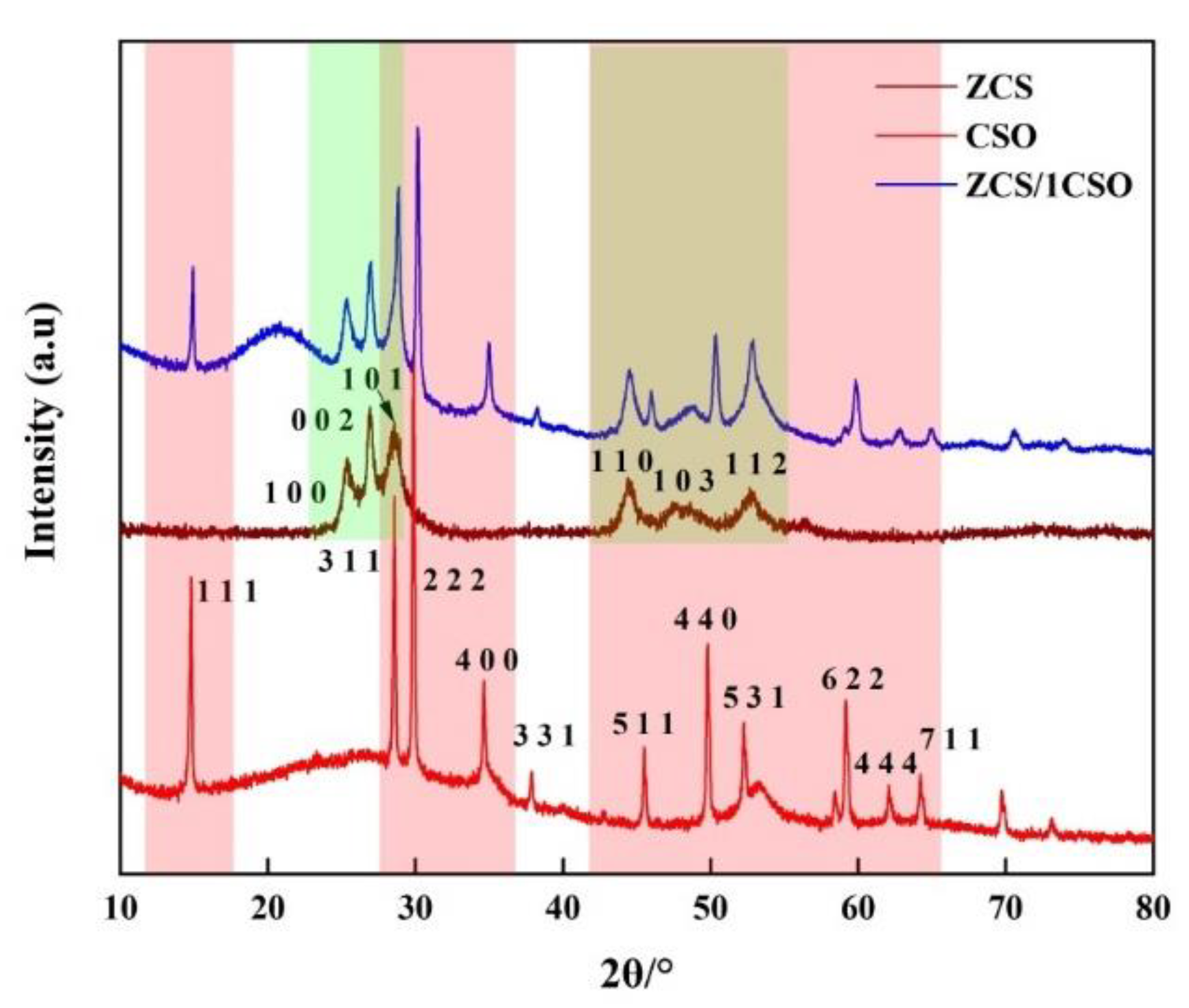
3.1. XRD
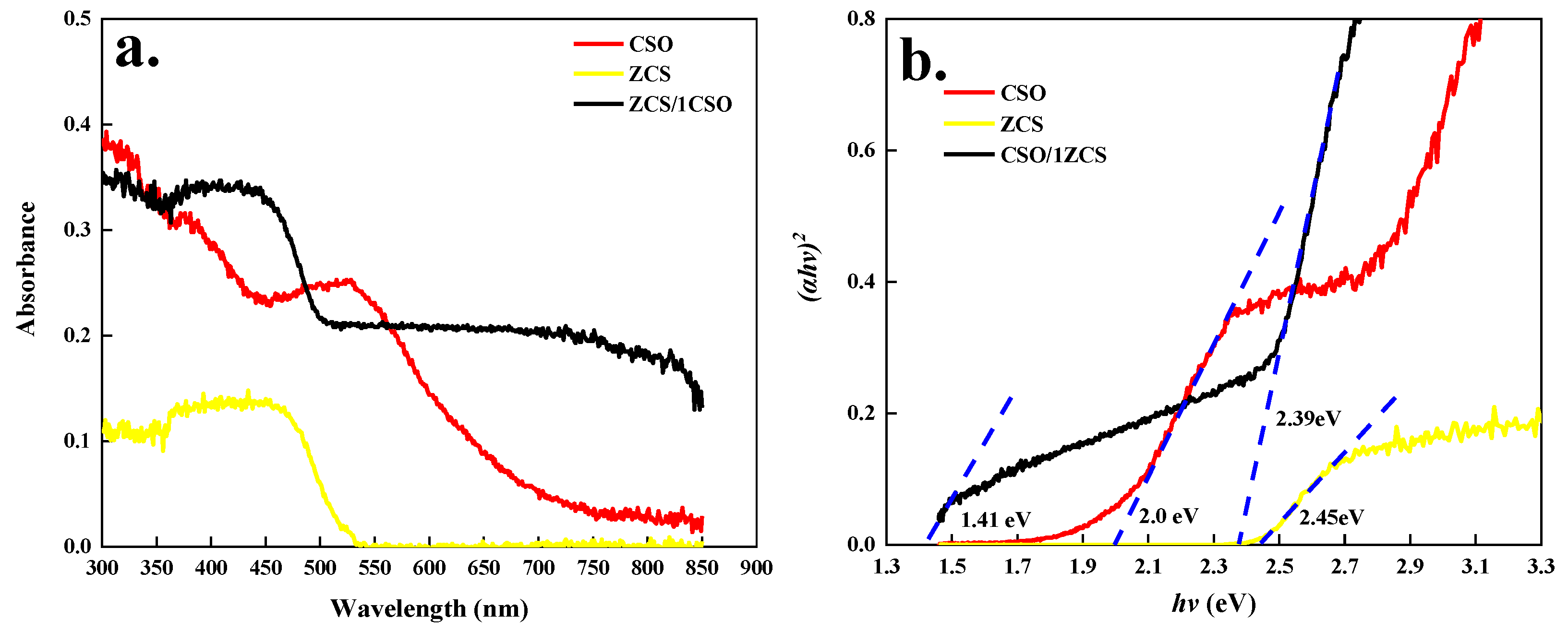
3.2. UV–Vis DRS
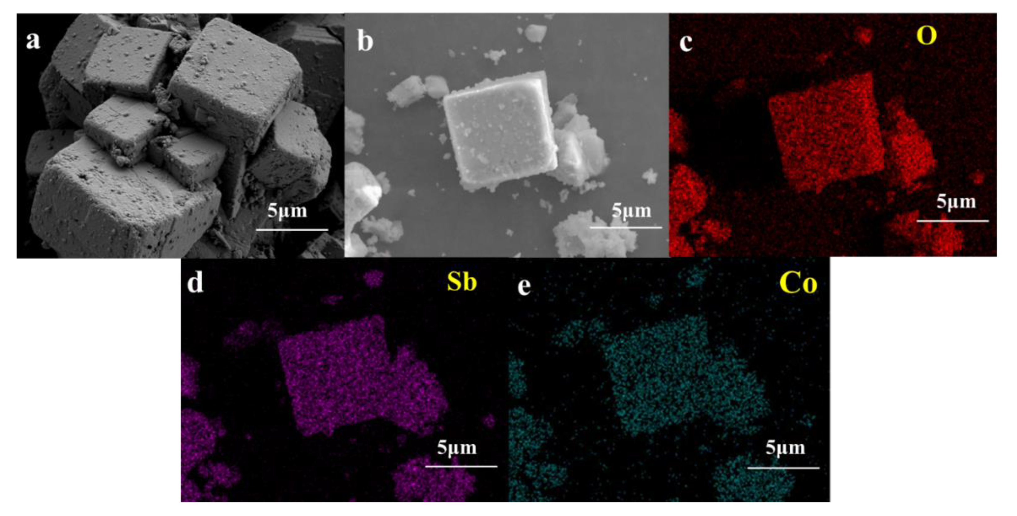
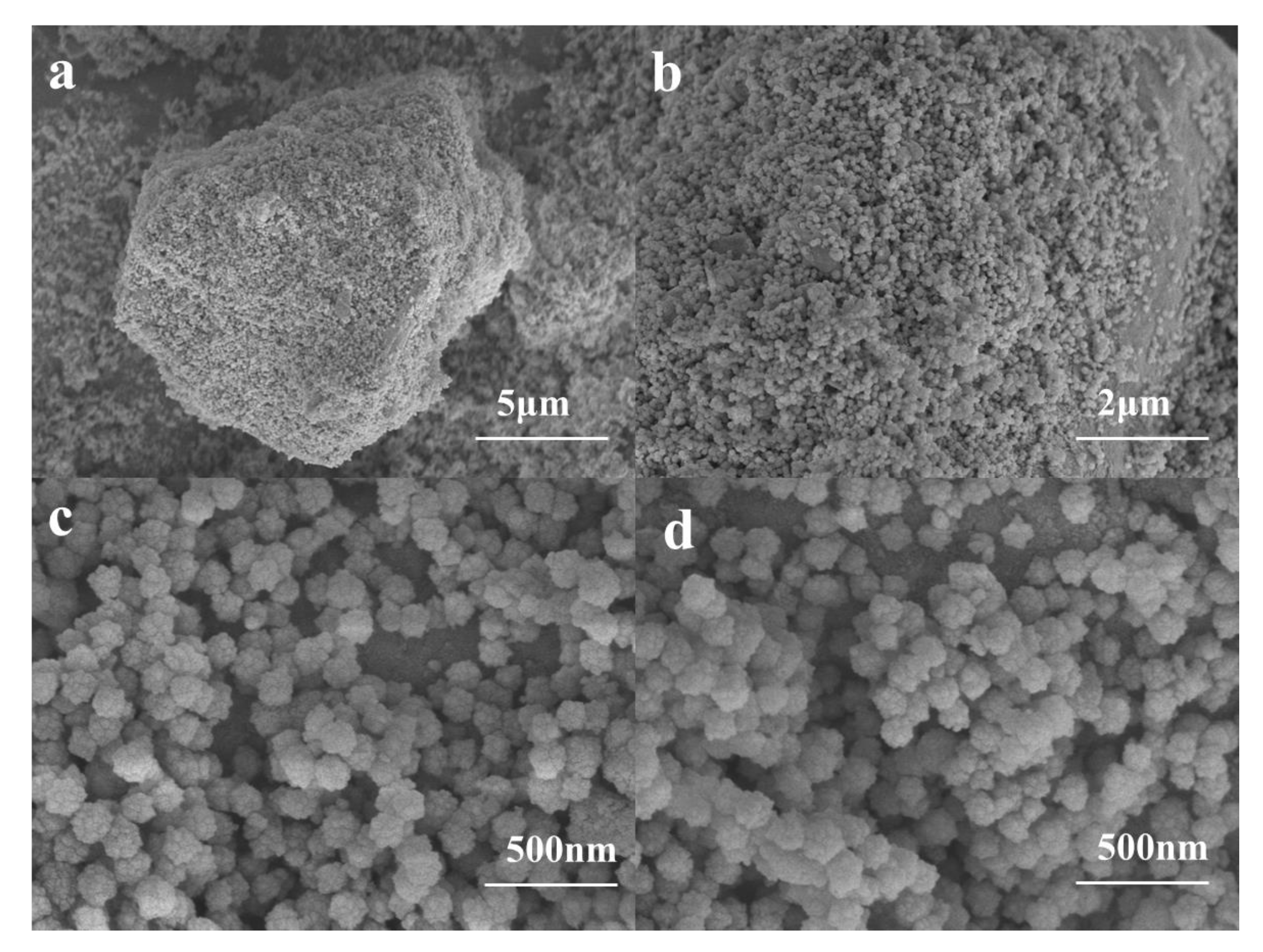
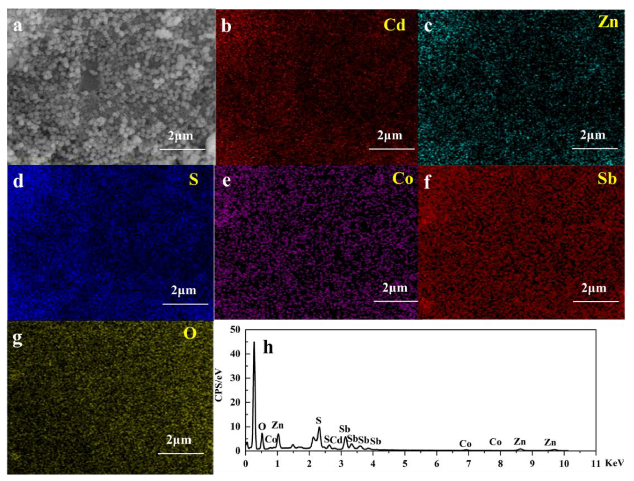
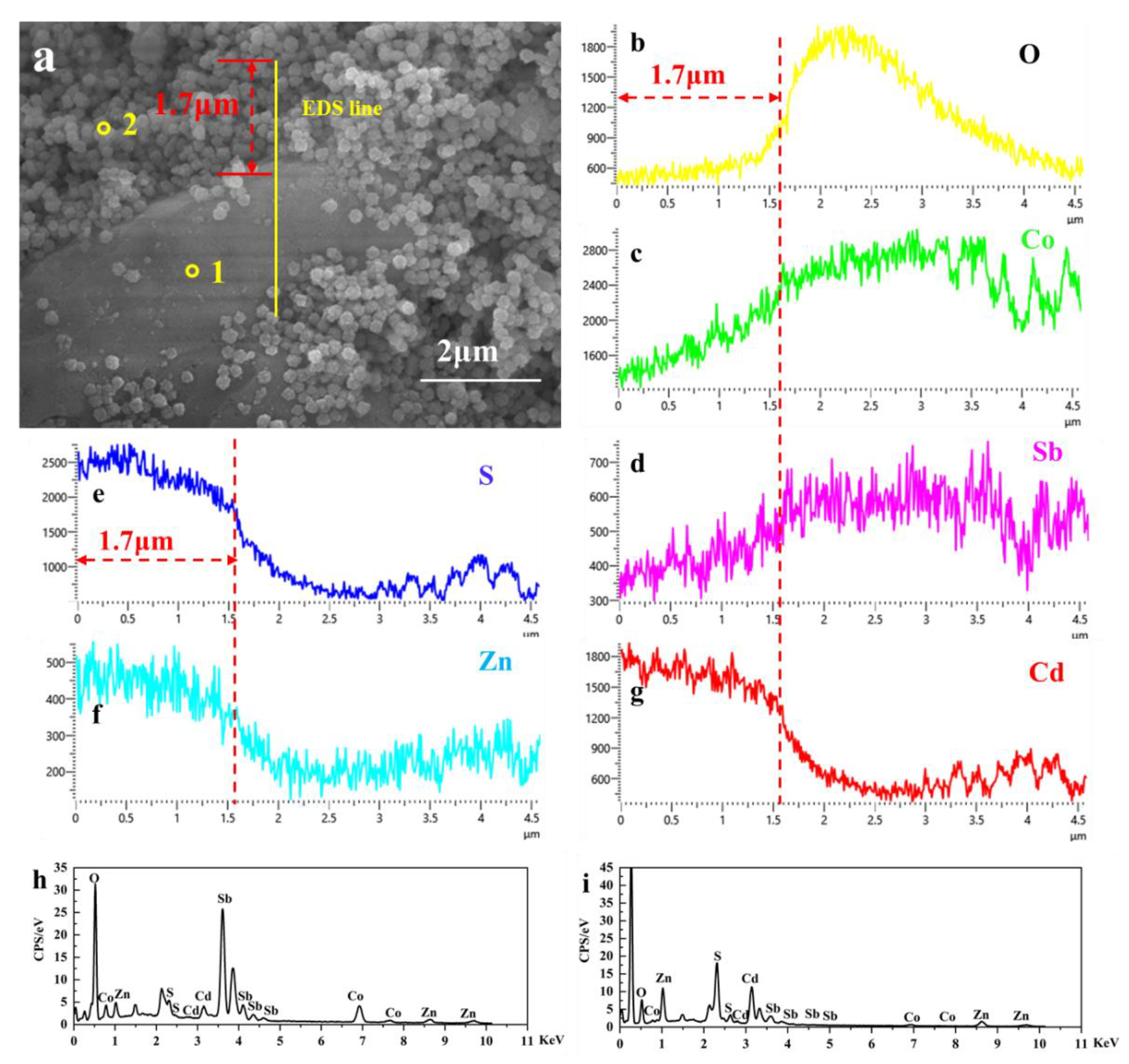
3.3. SEM-EDX
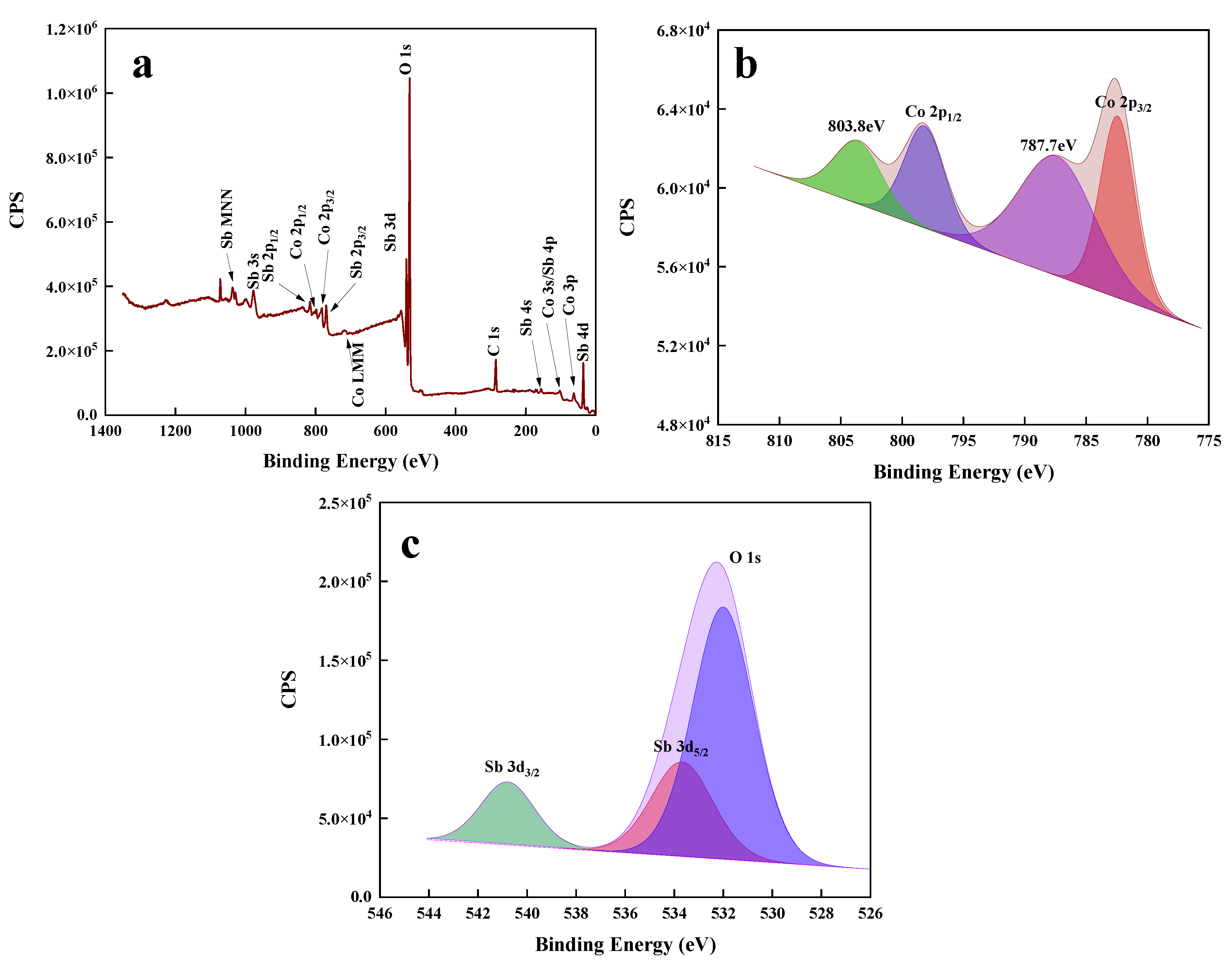
3.4. XPS
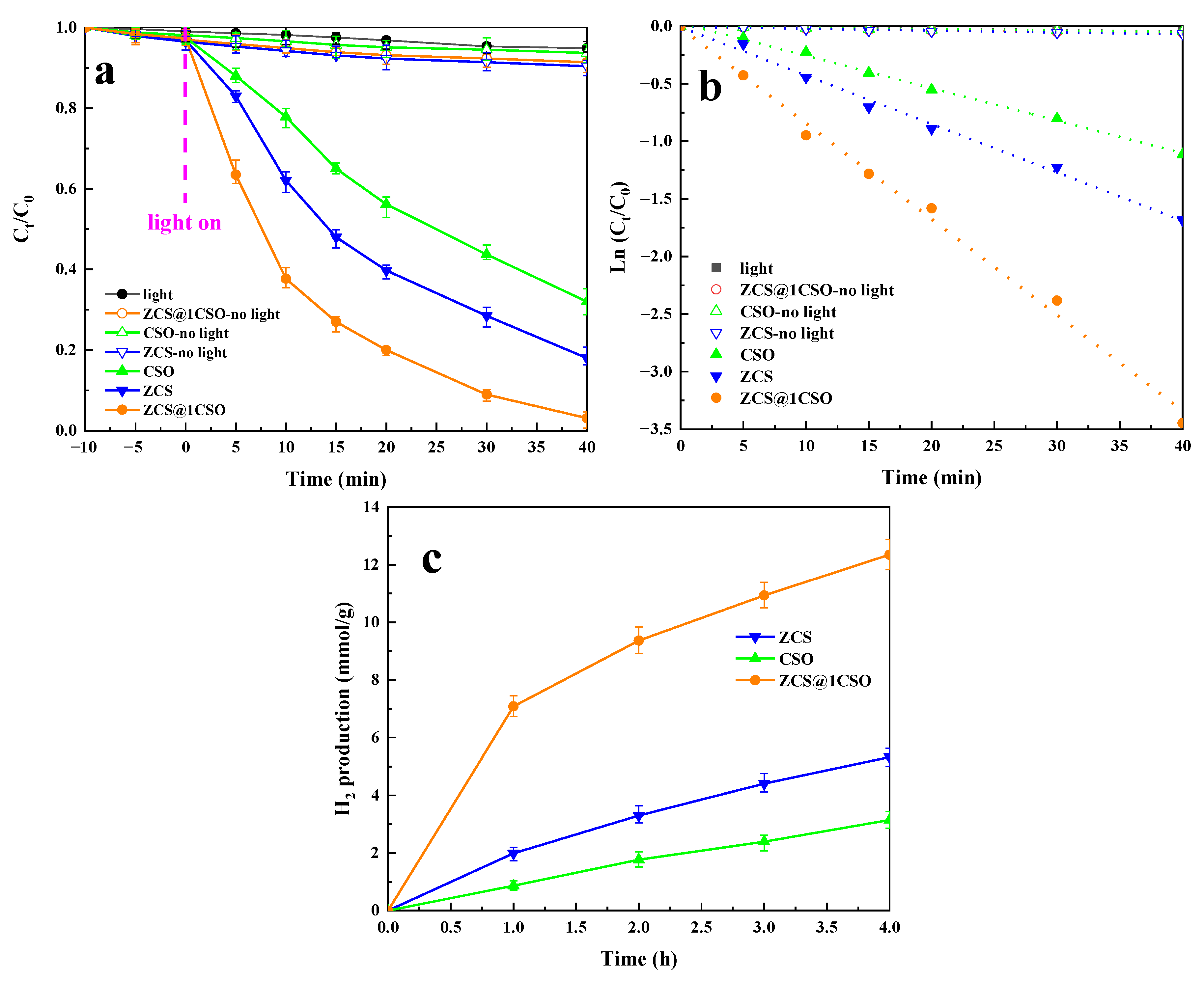
3.5. The Photocatalysis Performance
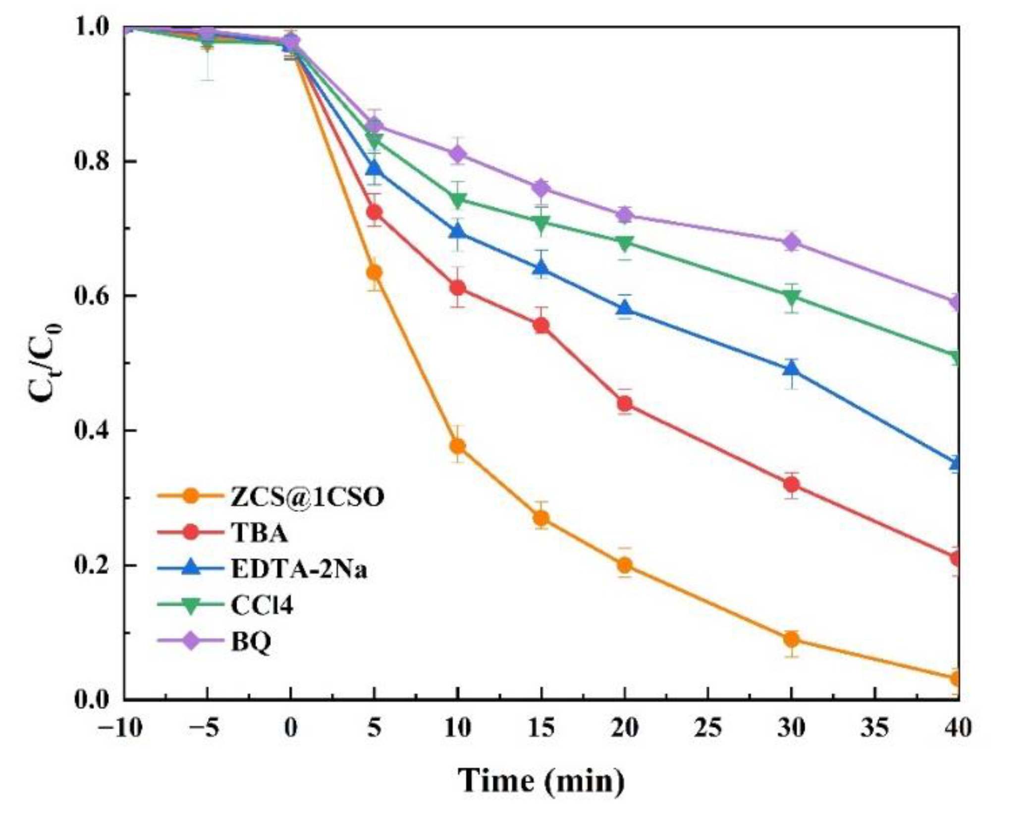
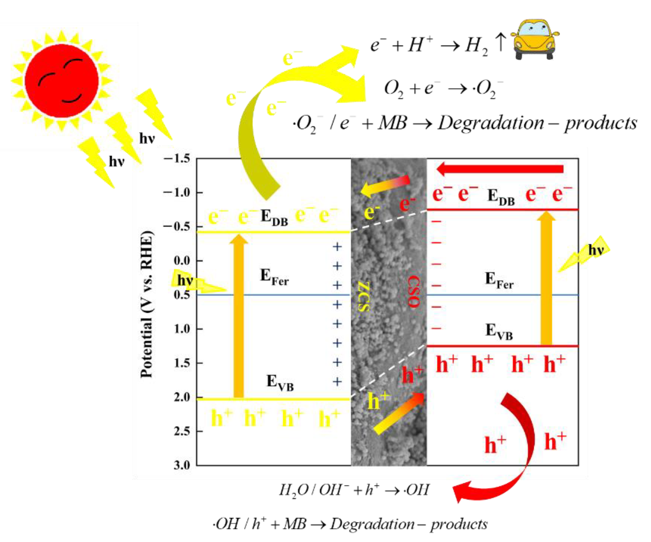
3.6. The Photocatalysis Mechanism
4. Conclusions
Supplementary Materials
Author Contributions
Funding
Data Availability Statement
Conflicts of Interest
References
- Li, L.; Shi, Y.; Huang, Y.; Xing, A.; Xue, H. The Effect of Governance on Industrial Wastewater Pollution in China. Int. J. Environ. Res. Public Health 2022, 19, 9316. [Google Scholar] [CrossRef] [PubMed]
- Tang, W.; Pei, Y.; Zheng, H.; Zhao, Y.; Shu, L.; Zhang, H. Twenty years of China’s water pollution control: Experiences and challenges. Chemosphere 2022, 295, 133875. [Google Scholar] [CrossRef] [PubMed]
- Jia, Z.; Lin, B. How to achieve the first step of the carbon-neutrality 2060 target in China: The coal substitution perspective. Energy 2021, 233, 121179. [Google Scholar] [CrossRef]
- Li, Y.; Yang, X.; Ran, Q.; Wu, H.; Irfan, M.; Ahmad, M. Energy structure, digital economy, and carbon emissions: Evidence from China. Environ. Sci. Pollut. Res. 2021, 28, 64606–64629. [Google Scholar] [CrossRef]
- Bhat, A.H.; Rangreez, T.A.; Inamuddin; Chisti, H.-T.-N. Wastewater Treatment and Biomedical Applications of Montmorillonite Based Nanocomposites: A Review. Curr. Anal. Chem. 2022, 18, 269–287. [Google Scholar] [CrossRef]
- Morin-Crini, N.; Lichtfouse, E.; Fourmentin, M.; Ribeiro, A.R.L.; Noutsopoulos, C.; Mapelli, F.; Fenyvesi, E.; Vieira, M.G.A.; Picos-Corrales, L.A.; Moreno-Pirajan, J.C.; et al. Removal of emerging contaminants from wastewater using advanced treatments. A review. Environ. Chem. Lett. 2022, 20, 1333–1375. [Google Scholar] [CrossRef]
- Wang, B.W.; Wang, Y. A comprehensive review on persulfate activation treatment of wastewater. Sci. Total Environ. 2022, 831, 154906. [Google Scholar] [CrossRef]
- Garcia-Segura, S.; Ocon, J.D.; Chong, M.N. Electrochemical oxidation remediation of real wastewater effluents—A review. Process Saf. Environ. Prot. 2018, 113, 48–67. [Google Scholar] [CrossRef]
- Kasonga, T.K.; Coetzee, M.A.A.; Kamika, I.; Ngole-Jeme, V.M.; Momba, M.N.B. Endocrine-disruptive chemicals as contaminants of emerging concern in wastewater and surface water: A review. J. Environ. Manag. 2021, 277, 111485. [Google Scholar] [CrossRef]
- Schneider, S.L.; Lim, H.W. Review of environmental effects of oxybenzone and other sunscreen active ingredients. J. Am. Acad. Dermatol. 2019, 80, 266–271. [Google Scholar] [CrossRef]
- Alabi, O.A. Comparative chemical analysis, mutagenicity, and genotoxicity of Petroleum refinery wastewater and its contaminated river using prokaryotic and eukaryotic assays. Protoplasma 2022, 1–13. [Google Scholar] [CrossRef] [PubMed]
- Xue, P.; Zhao, Y.; Zhao, D.; Chi, M.; Yin, Y.; Xuan, Y.; Wang, X. Mutagenicity, health risk, and disease burden of exposure to organic micropollutants in water from a drinking water treatment plant in the Yangtze River Delta, China. Ecotoxicol. Environ. Saf. 2021, 221, 112421. [Google Scholar] [CrossRef] [PubMed]
- Jirova, G.; Wittlingerova, Z.; Zimova, M.; Vlkova, A.; Wittlerova, M.; Dvorakova, M.; Jirova, D. Bioindicators of wastewater ecotoxicity. Neuroendocrinol. Lett. 2016, 37, 17–24. [Google Scholar] [PubMed]
- Koopaei, N.N.; Abdollahi, M. Health risks associated with the pharmaceuticals in wastewater. Daru-J. Pharm. Sci. 2017, 25, 9. [Google Scholar] [CrossRef] [PubMed] [Green Version]
- Lin, S.-S.; Shen, S.-L.; Zhou, A.; Lyu, H.-M. Assessment andmanagement of lake eutrophication: A case study in Lake Erhai, China. Sci. Total Environ. 2021, 751, 141618. [Google Scholar] [CrossRef]
- Preisner, M.; Neverova-Dziopak, E.; Kowalewski, Z. Analysis of eutrophication potential of municipal wastewater. Water Sci. Technol. 2020, 81, 1994–2003. [Google Scholar] [CrossRef]
- Panagopoulos, A. Brine management (saline water & wastewater effluents): Sustainable utilization and resource recovery strategy through Minimal and Zero Liquid Discharge (MLD & ZLD) desalination systems. Chem. Eng. Process. Process Intensif. 2022, 176, 108944. [Google Scholar] [CrossRef]
- Panagopoulos, A.; Giannika, V. Decarbonized and circular brine management/valorization for water & valuable resource recovery via minimal/zero liquid discharge (MLD/ZLD) strategies. J. Environ. Manag. 2022, 324, 116239. [Google Scholar] [CrossRef]
- Panagopoulos, A. Process simulation and analysis of high-pressure reverse osmosis (HPRO) in the treatment and utilization of desalination brine (saline wastewater). Int. J. Energy Res. 2022. [Google Scholar] [CrossRef]
- Chen, C.X.; Xiong, Y.Y.; Zhong, X.; Lan, P.C.; Wei, Z.W.; Pan, H.; Su, P.Y.; Song, Y.; Chen, Y.F.; Nafady, A.; et al. Enhancing Photocatalytic Hydrogen Production via the Construction of Robust Multivariate Ti-MOF/COF Composites. Angew. Chem. Int. Ed. 2022, 61, e202114071. [Google Scholar] [CrossRef]
- Guo, Y.; Liang, Z.; Xue, Y.; Wang, X.; Zhang, X.; Tian, J. A cation exchange strategy to construct Rod-shell CdS/Cu2S nanostructures for broad spectrum photocatalytic hydrogen production. J. Colloid Interface Sci. 2022, 608, 158–163. [Google Scholar] [CrossRef] [PubMed]
- Liang, Z.; Shen, R.; Ng, Y.H.; Zhang, P.; Xiang, Q.; Li, X. A review on 2D MoS2 cocatalysts in photocatalytic H-2 production. J. Mater. Sci. Technol. 2020, 56, 89–121. [Google Scholar] [CrossRef]
- Chen, D.; Cheng, Y.; Zhou, N.; Chen, P.; Wang, Y.; Li, K.; Huo, S.; Cheng, P.; Peng, P.; Zhang, R.; et al. Photocatalytic degradation of organic pollutants using TiO2-based photocatalysts: A review. J. Clean. Prod. 2020, 268, 121725. [Google Scholar] [CrossRef]
- Liu, Z.; Yu, Y.; Zhu, X.; Fang, J.; Xu, W.; Hu, X.; Li, R.; Yao, L.; Qin, J.; Fang, Z. Semiconductor heterojunctions for photocatalytic hydrogen production and Cr(VI) Reduction: A review. Mater. Res. Bull. 2022, 147, 111636. [Google Scholar] [CrossRef]
- Cheung, K.P.S.; Sarkar, S.; Gevorgyan, V. Visible Light-Induced Transition Metal Catalysis. Chem. Rev. 2022, 122, 1543–1625. [Google Scholar] [CrossRef]
- Gao, C.; Low, J.; Long, R.; Kong, T.; Zhu, J.; Xiong, Y. Heterogeneous Single-Atom Photocatalysts: Fundamentals and Applications. Chem. Rev. 2020, 120, 12175–12216. [Google Scholar] [CrossRef]
- Jin, P.; Wang, L.; Ma, X.; Lian, R.; Huang, J.; She, H.; Zhang, M.; Wang, Q. Construction of hierarchical ZnIn2S4@PCN-224 heterojunction for boosting photocatalytic performance in hydrogen production and degradation of tetracycline hydrochloride. Appl. Catal. B-Environ. 2021, 284, 119762. [Google Scholar] [CrossRef]
- Chen, C.; Cheng, T.; Wang, L.; Xu, Y.; Zhang, X. Surface functionalization of Linde F (K) nano-zeolite and its application for photocatalytic wastewater treatment and hydrogen production. Appl. Phys. A 2022, 128, 468. [Google Scholar] [CrossRef]
- Juárez-Cortazar, D.E.; Torres-Torres, J.G.; Hernandez-Ramirez, A.; Arévalo-Pérez, J.C.; Cervantes-Uribe, A.; Godavarthi, S.; de los Monteros, A.E.E.; Silahua-Pavón, A.A.; Cordero-Garcia, A. Doping of TiO2 Using Metal Waste (Door Key) to Improve Its Photocatalytic Efficiency in the Mineralization of an Emerging Contaminant in an Aqueous Environment. Water 2022, 14, 1389. [Google Scholar] [CrossRef]
- Park, Y.; Kim, S.; Kim, J.; Khan, S.; Han, C. UV/TiO2 Photocatalysis as an Efficient Livestock Wastewater Quaternary Treatment for Antibiotics Removal. Water 2022, 14, 958. [Google Scholar] [CrossRef]
- Asadzadeh-Khaneghah, S.; Habibi-Yangjeh, A. g-C3N4/carbon dot-based nanocomposites serve as efficacious photocatalysts for environmental purification and energy generation: A review. J. Clean. Prod. 2020, 276, 124319. [Google Scholar] [CrossRef]
- He, F.; Zhu, B.; Cheng, B.; Yu, J.; Ho, W.; Macyk, W. 2D/2D/0D TiO2/C3N4/Ti3C2 MXene composite S-scheme photocatalyst with enhanced CO2 reduction activity. Appl. Catal. B-Environ. 2020, 272, 119006. [Google Scholar] [CrossRef]
- Smazna, D.; Shree, S.; Polonskyi, O.; Lamaka, S.; Baum, M.; Zheludkevich, M.; Faupel, F.; Adelung, R.; Mishra, Y.K. Mutual interplay of ZnO micro- and nanowires and methylene blue during cyclic photocatalysis process. J. Environ. Chem. Eng. 2019, 7, 103016. [Google Scholar] [CrossRef]
- Pan, L.; Muhammad, T.; Ma, L.; Huang, Z.-F.; Wang, S.; Wang, L.; Zou, J.-J.; Zhang, X. MOF-derived C-doped ZnO prepared via a two-step calcination for efficient photocatalysis. Appl. Catal. B-Environ. 2016, 189, 181–191. [Google Scholar] [CrossRef]
- Sun, B.; Liang, Z.; Qian, Y.; Xu, X.; Han, Y.; Tian, J. Sulfur Vacancy-Rich O-Doped 1T-MoS2 Nanosheets for Exceptional Photocatalytic Nitrogen Fixation over CdS. ACS Appl. Mater. Interfaces 2020, 12, 7257–7269. [Google Scholar] [CrossRef]
- Wang, L.; Xie, L.; Zhao, W.; Liu, S.; Zhao, Q. Oxygen-facilitated dynamic active-site generation on strained MoS2 during photo-catalytic hydrogen evolution. Chem. Eng. J. 2021, 405, 127028. [Google Scholar] [CrossRef]
- Liu, Q.; Fan, C.; Liu, J.; Sun, X.; Cheng, X.; Li, H. Synthesis, photocatalytic performance and negative thermal expansion property of nanorods ZrMo2−x V(x) O8-x/2 with cubic structure. J. Sol-Gel Sci. Technol. 2015, 76, 279–288. [Google Scholar] [CrossRef]
- Chen, C.; Wen, M.; Cheng, T.; Wang, L.; Zhang, X.; Tian, Y. Photocatalytic degradation of tetracycline wastewater through heterojunction based on 2D rhombic ZrMo2O8 nanosheet and nano-TiO2. J. Nanoparticle Res. 2022, 24, 172. [Google Scholar] [CrossRef]
- Yin, H.; Cao, Y.; Fan, T.; Zhang, M.; Yao, J.; Li, P.; Chen, S.; Liu, X. In situ synthesis of Ag3PO4/C3N5 Z-scheme heterojunctions with enhanced visible-light-responsive photocatalytic performance for antibiotics removal. Sci. Total Environ. 2021, 754, 141926. [Google Scholar] [CrossRef]
- Mu, F.; Dai, B.; Zhao, W.; Zhou, S.; Huang, H.; Yang, G.; Xia, D.; Kong, Y.; Leung, D.Y.C. Construction of a novel Ag/Ag3 PO4 /MIL-68(In)-NH2 plasmonic heterojunction photocatalyst for high-efficiency photocatalysis. J. Mater. Sci. Technol. 2022, 101, 37–48. [Google Scholar] [CrossRef]
- Chen, C.; Wang, L.; Cheng, T.; Zhang, X.; Zhou, Z.; Zhang, X.; Xu, Q. Ag3PO4/AgSbO3 composite as novel photocatalyst with significantly enhanced activity through a Z-scheme degradation mechanism. J. Iran. Chem. Soc. 2022, 19, 821–838. [Google Scholar] [CrossRef]
- Liu, Y.; Zheng, X.; Yang, Y.; Song, Y.; Yang, Y.; Li, J.; Shim, C.M.; Shen, Y.; Tian, X. Recent Advances in the Hydrogen Evolution Reaction of ZnxCd1-xS-Based Photocatalysts. Sol. RRL 2022, 6, 2101061. [Google Scholar] [CrossRef]
- Madhusudan, P.; Shi, R.; Xiang, S.; Jin, M.; Chandrashekar, B.N.; Wang, J.; Wang, W.; Peng, O.; Amini, A.; Cheng, C. Construction of highly efficient Z-scheme ZnxCd1−xS/Au@g-C3N4 ternary heterojunction composite for visible-light-driven photocatalytic reduction of CO2 to solar fuel. Appl. Catal. B-Environ. 2021, 282, 119600. [Google Scholar] [CrossRef]
- Shen, R.C.; Ding, Y.N.; Li, S.B.; Zhang, P.; Xiang, Q.J.; Ng, Y.H.; Li, X. Constructing low-cost Ni3C/twin-crystal Zn0.5Cd0.5S heterojunction/homojunction nanohybrids for efficient photocatalytic H-2 evolution. Chin. J. Catal. 2021, 42, 25–36. [Google Scholar] [CrossRef]
- Ge, G.Y.; Yuan, S.T.; Liu, Q.Z.; Yang, D.F.; Shi, J.S.; Lan, X.F.; Xiao, K.F. Insight into the function of noble-metal free Cu3P decorated Zn0.5Cd0.5S for enhanced photocatalytic hydrogen evolution under visible light irradiation- mechanism for continuous increasing activity. Appl. Surf. Sci. 2022, 597, 153660. [Google Scholar] [CrossRef]
- Liu, H.; Zhang, Y.Y.; Li, D.J.; Li, Y.J.; Jin, Z.L. Design and Preparation of a CeVO4/Zn0.5Cd0.5S S-Scheme Heterojunction for Efficient Photocatalytic Hydrogen Evolution. ACS Appl. Energy Mater. 2022, 5, 2474–2483. [Google Scholar] [CrossRef]
- Qi, S.Y.; Zhang, K.Y.; Zhang, Y.M.; Zhang, R.Y.; Xu, H.Y. Synthesis of WS2/Zn0.5Cd0.5S Nanoheterostructured Photocatalyst and Its Visible Light Catalytic Performance. J. Inorg. Organomet. Polym. Mater. 2022, 32, 3923–3931. [Google Scholar] [CrossRef]
- Duo, J.; Li, W.; Wang, Y.; Wang, S.; Wufuer, R.; Pan, X. Photothermal Catalytic Degradation of Lomefloxacin with Nano Au/TiO2. Water 2022, 14, 339. [Google Scholar] [CrossRef]
- Chen, C.; Wang, L.; Cheng, T.; Zhang, X.; Tian, Y.; Shi, Y. Sliver Doped Sodium Antimonate with Greatly Reduced the Band Gap for Efficiently Enhanced Photocatalytic Activities Under Visible Light (Experiment and DFT Calculation). Mater. Res. 2021, 24, e20210100. [Google Scholar] [CrossRef]
- Dai, D.; Xu, H.; Ge, L.; Han, C.; Gao, Y.; Li, S.; Lu, Y. In-situ synthesis of CoP co-catalyst decorated Zn0.5Cd0.5S photocatalysts with enhanced photocatalytic hydrogen production activity under visible light irradiation. Appl. Catal. B Environ. 2017, 217, 429–436. [Google Scholar] [CrossRef]
- Tang, Y.; Li, X.; Zhang, D.; Pu, X.; Ge, B.; Huang, Y. Noble metal-free ternary MoS2/Zn0.5Cd0.5S/g-C3N4 heterojunction composite for highly efficient photocatalytic H2 production. Mater. Res. Bull. 2019, 110, 214–222. [Google Scholar] [CrossRef]
- Ham, K.; Hong, S.; Kang, S.; Cho, K.; Lee, J. Extensive Active-Site Formation in Trirutile CoSb2O6 by Oxygen Vacancy for Oxygen Evolution Reaction in Anion Exchange Membrane Water Splitting. ACS Energy Lett. 2021, 6, 364–370. [Google Scholar] [CrossRef]
- Evans, T.A.; Choi, K.-S. Electrochemical Synthesis and Investigation of Stoichiometric, Phase-Pure CoSb2O6 and MnSb2O6Electrodes for the Oxygen Evolution Reaction in Acidic Media. ACS Appl. Energy Mater. 2020, 3, 5563–5571. [Google Scholar] [CrossRef]
- Zhang, X.; Cheng, T.; Chen, C.; Wang, L.; Deng, Q.; Chen, G.; Ye, C. Synthesis of a novel magnetic nano-zeolite and its application as an efficient heavy metal adsorbent. Mater. Res. Express 2020, 7, 085007. [Google Scholar] [CrossRef]
- Nutescu Duduman, C.; Gómez de Castro, C.; Apostolescu, G.A.; Ciobanu, G.; Lutic, D.; Favier, L.; Harja, M. Enhancing the TiO2-Ag Photocatalytic Efficiency by Acetone in the Dye Removal from Wastewater. Water 2022, 14, 2711. [Google Scholar] [CrossRef]
- Yasin, A.; Fatima, U.; Shahid, S.; Mansoor, S.; Inam, H.; Javed, M.; Iqbal, S.; Alrbyawi, H.; Somaily, H.H.; Pashameah, R.A.; et al. Fabrication of Copper Oxide Nanoparticles Using Passiflora edulis Extract for the Estimation of Antioxidant Potential and Photocatalytic Methylene Blue Dye Degradation. Agronomy 2022, 12, 2315. [Google Scholar] [CrossRef]
- Umar, A.; Kumar, S.A.; Rosaline, D.R.; Algadi, H.; Ibrahim, A.A.; Ahmed, F.; Foletto, E.L.; Inbanathan, S.S.R. Poly(1-Napthylamine) Nanoparticles as Potential Scaffold for Supercapacitor and Photocatalytic Applications. Micromachines 2022, 13, 1528. [Google Scholar] [CrossRef]
- Li, G.; Zeng, G.; Chen, Z.; Hong, J.; Ji, X.; Lan, Z.; Tan, X.; Li, M.; Hu, X.; Tang, C. In Situ Coupling Carbon Defective C3N5 Nanosheet with Ag2CO3 for Effective Degradation of Methylene Blue and Tetracycline Hydrochloride. Nanomaterials 2022, 12, 2701. [Google Scholar] [CrossRef]
- Dhatwalia, J.; Kumari, A.; Chauhan, A.; Mansi, K.; Thakur, S.; Saini, R.V.; Guleria, I.; Lal, S.; Kumar, A.; Batoo, K.M.; et al. Rubus ellipticus Sm. Fruit Extract Mediated Zinc Oxide Nanoparticles: A Green Approach for Dye Degradation and Biomedical Applications. Materials 2022, 15, 3470. [Google Scholar] [CrossRef]
- Ma, X.; Zhou, W.; Chen, Y. Structure and Photocatalytic Properties of Mn-Doped TiO2 Loaded on Wood-Based Activated Carbon Fiber Composites. Materials 2017, 10, 631. [Google Scholar] [CrossRef]
- Shahabuddin, S.; Muhamad Sarih, N.; Mohamad, S.; Joon Ching, J. SrTiO3 Nanocube-Doped Polyaniline Nanocomposites with Enhanced Photocatalytic Degradation of Methylene Blue under Visible Light. Polymers 2016, 8, 27. [Google Scholar] [CrossRef] [PubMed] [Green Version]
- Liu, L.-L.; Yu, C.-X.; Zhou, W.; Zhang, Q.-G.; Liu, S.-M.; Shi, Y.-F. Construction of Four Zn(II) Coordination Polymers Used as Catalysts for the Photodegradation of Organic Dyes in Water. Polymers 2016, 8, 3. [Google Scholar] [CrossRef] [PubMed]
- Ara, A.; Khattak, R.; Khan, M.S.; Begum, B.; Khan, S.; Han, C. Synthesis, Characterization, and Solar Photo-Activation of Chitosan-Modified Nickel Magnetite Bio-Composite for Degradation of Recalcitrant Organic Pollutants in Water. Catalysts 2022, 12, 983. [Google Scholar] [CrossRef]
- Malik, S.B.; Saggu, J.I.; Gul, A.; Abbasi, B.A.; Iqbal, J.; Waris, S.; Jardan, Y.A.B.; Chalgham, W. Synthesis and Characterization of Silver and Graphene Nanocomposites and Their Antimicrobial and Photocatalytic Potentials. Molecules 2022, 27, 5184. [Google Scholar] [CrossRef]
- Jawhari, A.H.; Hasan, N.; Radini, I.A.; Narasimharao, K.; Malik, M.A. Noble Metals Deposited LaMnO3 Nanocomposites for Photocatalytic H2 Production. Nanomaterials 2022, 12, 2985. [Google Scholar] [CrossRef]
- Tang, S.; Xu, Y.-S.; Zhang, W.-D. Embedding Thiophene-Amide into g-C3N4 Skeleton with Induction and Delocalization Effects for High Photocatalytic H2 Evolution. Protoplasma 2022, 12, 1043. [Google Scholar] [CrossRef]
- Chen, Y.; Li, A.; Fu, X.; Peng, Z. One-Step Calcination to Gain Exfoliated g-C3N4/MoO2 Composites for High-Performance Photocatalytic Hydrogen Evolution. Molecules 2022, 27, 7178. [Google Scholar] [CrossRef]
- Pantoja-Espinoza, J.C.; Domínguez-Arvizu, J.L.; Jiménez-Miramontes, J.A.; Hernández-Majalca, B.C.; Meléndez-Zaragoza, M.J.; Salinas-Gutiérrez, J.M.; Herrera-Pérez, G.M.; Collins-Martínez, V.H.; López-Ortiz, A. Comparative Study of Zn2Ti3O8 and ZnTiO3 Photocatalytic Properties for Hydrogen Production. Catalysts 2020, 10, 1372. [Google Scholar] [CrossRef]
- Chiang, T.H.; Viswanath, G.; Chen, Y.-S. Effects of RhCrOx Cocatalyst Loaded on Different Metal Doped LaFeO3 Perovskites with Photocatalytic Hydrogen Performance under Visible Light Irradiation. Catalysts 2021, 11, 612. [Google Scholar] [CrossRef]
- Zhang, T.; Liu, P.; Wang, L.; Wang, S.; Shi, J.; Lan, X. Electronegativity Assisted Synthesis of Magnetically Recyclable Ni/NiO/g-C3N4 for Significant Boosting H2 Evolution. Materials 2021, 14, 2894. [Google Scholar] [CrossRef]
- Zou, Y.; Guo, C.; Cao, X.; Chen, T.; Kou, Y.; Zhang, L.; Wang, T.; Akram, N.; Wang, J. Photocatalytic performance and mechanism of hydrogen evolution from water over ZnCdS/Co@CoO in sacrificial agent-free system. Int. J. Hydrogen Energy 2022, 47, 25289–25299. [Google Scholar] [CrossRef]
- Wang, Y.; Jin, H.; Li, Y.; Fang, J.; Chen, C. Ce-based organic framework enhanced the hydrogen evolution ability of ZnCdS photocatalyst. Int. J. Hydrogen Energy 2022, 47, 962–970. [Google Scholar] [CrossRef]
- Ji, Y.; Zhou, Y.; Wang, J.; Li, A.; Bian, W.; Corvini, P.F.-X. Au@CoS-BiVO4 (010) Constructed for Visible-Light-Assisted Peroxymonosulfate Activation. Catalysts 2021, 11, 1414. [Google Scholar] [CrossRef]
- Gao, J.; Zhang, F.; Xue, H.; Zhang, L.; Peng, Y.; Li, X.; Gao, Y.; Li, N.; Lei, G. In-situ synthesis of novel ternary CdS/PdAg/g-C3N4 hybrid photocatalyst with significantly enhanced hydrogen production activity and catalytic mechanism exploration. Appl. Catal. B Environ. 2021, 281, 119509. [Google Scholar] [CrossRef]
- Li, X.-L.; Yang, G.Q.; Li, S.S.; Xiao, N.; Li, N.; Gao, Y.Q.; Lv, D.; Ge, L. Novel dual co-catalysts decorated Au@HCS@PdS hybrids with spatially separated charge carriers and enhanced photocatalytic hydrogen evolution activity. Chem. Eng. J. 2020, 379, 122350. [Google Scholar] [CrossRef]
- Zhu, H.; Ji, Y.; Chen, L.; Bian, W.; Wang, J. Pt Nanowire-Anchored Dodecahedral Ag3PO4{110} Constructed for Significant Enhancement of Photocatalytic Activity and Anti-Photocorrosion Properties: Spatial Separation of Charge Carriers and PhotogeneratedElectron Utilization. Catalysts 2020, 10, 206. [Google Scholar] [CrossRef] [Green Version]
- Huo, H.; Hu, X.; Wang, H.; Li, J.; Xie, G.; Tan, X.; Jin, Q.; Zhou, D.; Li, C.; Qiu, G.; et al. Synergy of Photocatalysis and Adsorption for Simultaneous Removal of Hexavalent Chromium and Methylene Blue by g-C3N4/BiFeO3/Carbon Nanotubes Ternary Composites. Int. J. Environ. Res. Public Health 2019, 16, 3219. [Google Scholar] [CrossRef] [Green Version]
- Chen, F.F.; Wu, C.Y.; Wang, J.N.; Francois-Xavier, C.P.; Wintgens, T. Highly efficient Z-scheme structured visible-light photocatalyst constructed by selective doping of Ag@AgBr and Co3O4 separately on {010} and {110} facets of BiVO4: Pre-separation channel and hole-sink effects. Appl. Catal. B-Environ. 2019, 250, 31–41. [Google Scholar] [CrossRef]
- Liu, H.; Chen, H.; Ding, N. Visible Light-Based Ag3PO4/g-C3N4@MoS2 for Highly Efficient Degradation of 2-Amino-4-acetylaminoanisole (AMA) from Printing and Dyeing Wastewater. Int. J. Environ. Res. Public Health 2022, 19, 2934. [Google Scholar] [CrossRef]


| Different Reaction System | MB Degradation Rate Constant | Standard Deviation | R2 | Apparent H2 Production Rate Constant (mmol·g−1·h−1) |
|---|---|---|---|---|
| light | 0.00116 | 0.0000707 | 0.9780 | - |
| ZCS-no light | 0.00161 | 0.0001387 | 0.9476 | - |
| CSO-no light | 0.00115 | 0.0001060 | 0.9509 | - |
| ZCS@1CSO-no light | 0.00147 | 0.0001535 | 0.9486 | - |
| ZCS | 0.0421 | 0.0006465 | 0.9931 | 1.332 |
| CSO | 0.0282 | 0.000143 | 0.9969 | 0.787 |
| [email protected] | 0.0483 | 0.000186 | 0.9912 | 2.023 |
| [email protected] | 0.0544 | 0.000182 | 0.9933 | 2.395 |
| [email protected] | 0.0619 | 0.000223 | 0.9922 | 2.861 |
| ZCS@1CSO | 0.0832 | 0.000282 | 0.9932 | 3.087 |
| [email protected] | 0.0519 | 0.00015 | 0.9934 | 2.608 |
| [email protected] | 0.0442 | 0.000147 | 0.9950 | 2.197 |
| Catalysts | Light Source | Concentration (mg/L) | Dosage (mg/mL) | Ct/C0 at 40 min | Reference |
|---|---|---|---|---|---|
| copper oxide nanoparticle | sunlight | 5 | 2 | 0.917 | [56] |
| Poly(1-Napthylamine) nanoparticles | 11 W UV irradiation | 5 | 0.25 | 0.83 | [57] |
| C3N5 nanosheet with Ag2CO3 | 300 W Xe light | 60 | 1 | 0.28 | [58] |
| ZnO-nanoparticles | sunlight | 10 | 0.5 | 0.87 | [59] |
| (Mn/TiO2-WACF) | 300 W Xe light | 33 | 0.1 | 0.63 | [60] |
| SrTiO3 nanocube-doped polyaniline nanocomposites | 300 W Xe light | 10 | 0.3 | 0.29 | [61] |
| Zn(II) coordination polymers | 350 W Xe light | 12.8 | 0.4 | 0.38 | [62] |
| chitosan-modified nickel magnetite | sunlight | 50 | 16.7 | 0.58 | [63] |
| silver and graphene nanocomposites | 500 W Xe light | 3 | 0.4 | 0.7 | [64] |
| ZCS@1CSO | 300 W Xe light | 10 | 0.667 | 0.031 | this work |
| Catalysts | Light Source | Apparent H2 Production Rate Constant (mmol·g−1·h−1) | Reference |
|---|---|---|---|
| LaMnO3-Pt | 300 W Xe light | 1.350 | [65] |
| thiophene-amide embedded g-C3N4 | 300 W Xe light | 0.2454 | [66] |
| g-C3N4/MoO2 composites | 300 W Xe light | 0.3208 | [67] |
| cds-ZTO | 250 W metal-halide Philips lamp | 0.548 | [68] |
| RhCrOx/Pr-LaFeO3 | 300 W Xe light | 0.127 | [69] |
| Ni/NiO/g-C3N4 | 300 W Xe light | 2.310 | [70] |
| ZnCdS/Co@CoO | 300 W Xe light | 5.445 | [71] |
| UiO-66(Ce)/ZnCdS | 300 W Xe light | 3.958 | [72] |
| Rod-shell CdS/Cu2S | 300 W Xe light | 0.640 | [21] |
| ZCS@1CSO | 300 W Xe light | 3.087 | this work |
Publisher’s Note: MDPI stays neutral with regard to jurisdictional claims in published maps and institutional affiliations. |
© 2022 by the authors. Licensee MDPI, Basel, Switzerland. This article is an open access article distributed under the terms and conditions of the Creative Commons Attribution (CC BY) license (https://creativecommons.org/licenses/by/4.0/).
Share and Cite
Chen, C.; Zhang, X.; Cheng, T.; Wen, M.; Tian, Y.; Hou, B. Construction of Highly Efficient Zn0.4Cd0.6S and Cobalt Antimony Oxide Heterojunction Composites for Visible-Light-Driven Photocatalytic Hydrogen Evolution and Pollutant Degradation. Water 2022, 14, 3827. https://doi.org/10.3390/w14233827
Chen C, Zhang X, Cheng T, Wen M, Tian Y, Hou B. Construction of Highly Efficient Zn0.4Cd0.6S and Cobalt Antimony Oxide Heterojunction Composites for Visible-Light-Driven Photocatalytic Hydrogen Evolution and Pollutant Degradation. Water. 2022; 14(23):3827. https://doi.org/10.3390/w14233827
Chicago/Turabian StyleChen, Chen, Xiao Zhang, Ting Cheng, Mingyue Wen, Yuan Tian, and Baoxuan Hou. 2022. "Construction of Highly Efficient Zn0.4Cd0.6S and Cobalt Antimony Oxide Heterojunction Composites for Visible-Light-Driven Photocatalytic Hydrogen Evolution and Pollutant Degradation" Water 14, no. 23: 3827. https://doi.org/10.3390/w14233827