Article

Seismic Safety Assessment of Arch Dams Using an ETA-Based Method with Control of Tensile and Compressive Damage

1
Civil Engineering Department, Instituto Superior de Engenharia de Lisboa, Instituto Politécnico de Lisboa (ISEL-IPL), R. Conselheiro Emídio Navarro 1, 1959-007 Lisboa, Portugal
2
Concrete Dams Department, National Laboratory for Civil Engineering (LNEC), Av. do Brasil 101, 1700-075 Lisboa, Portugal
3
CERIS, Instituto Superior Técnico, Universidade de Lisboa (IST-ULisboa), Av. Rovisco Pais 1, 1049-001 Lisboa, Portugal
4
Hidroelétrica de Cahora Bassa, Office Headquarters, Songo 2304, Mozambique
*
Author to whom correspondence should be addressed.
Water 2022, 14(23), 3835; https://doi.org/10.3390/w14233835
Submission received: 21 October 2022 / Revised: 18 November 2022 / Accepted: 21 November 2022 / Published: 25 November 2022
(This article belongs to the Special Issue Soft Computing and Machine Learning in Dam Engineering)

Abstract

:
The seismic safety assessment of large concrete dams remains a significant challenge in dam engineering, as it requires appropriate analysis methods, modern performance criteria, and advanced numerical models to simulate the dam seismic behavior. This paper presents a method for seismic safety assessment of arch dams based on Endurance Time Analysis (ETA), using tensile and compressive damage results from a robust formulation for seismic analysis considering joint opening/sliding and concrete non-linear behavior (finite element program DamDySSA, under development in LNEC). The seismic performance is evaluated by controlling the evolution of the damage state of the dam, according to predefined performance criteria, to estimate acceleration endurance limits for tensile and compressive damage. These acceleration limits are compared, respectively, with the peak ground accelerations prescribed for the Operating Basis Earthquake (OBE) and Safety Evaluation Earthquake (SEE), aiming to evaluate the dam seismic performance relative to both earthquake levels efficiently, using a single intensifying acceleration time history. The ETA-based method is applied to the cases of Cabril Dam (132 m-high) and Cahora Bassa Dam (170 m-high), confirming its usefulness for future seismic safety studies, while the potential of DamDySSA for non-linear seismic analysis of arch dams is highlighted.

1. Introduction

1.1. Framework and Motivation

Large concrete dams are civil engineering structures with significant social, environmental, and economic impact. In fact, dams play a key role in the proper management of freshwater resources, namely for water supply, flood control, soil irrigation, and energy production, and they have become vital to populations and societies [1,2], not only due to the global increase in water demand, but also because of climate change [3]. Most dams are structures of high potential risk, since incidents or accidents may result in significant losses for populations and the environment [4]. For these reasons, dam engineers must ensure the best operational conditions and the structural safety of dams in normal service conditions and during exceptional events, under both static and dynamic loads.
In this context, emphasis should be given to the fact that many of the major concrete dams in operation or under construction are located in regions of high seismicity [5], and strong earthquakes can cause unacceptable joint openings or significant concrete damage that may require service interruption or even compromise structural integrity, among other incidents [6,7,8,9]; for example, in China, one of the regions with the highest seismic activity in the world, sophisticated experimental and numerical studies were carried out to support the design of new ultra-high concrete dams [10,11,12,13]. On the other hand, most of the older dams were built many decades ago, and thus designed using unreliable seismic analysis methods and outdated performance criteria. As such, the need to reassess the seismic safety of older dams based on modern practices has been identified; for example, in Switzerland, the seismic safety reassessment of all 208 large dams according to modern standards was required and carried out based on current approaches [14].
Therefore, appropriate methodologies and models should be developed to analyze the dynamic response of dams in normal operating conditions, aiming to control structural integrity over time and to evaluate the structural safety under seismic loads. The permanent structural health monitoring of dams can be conducted based on ambient/operational vibration analysis methods, to detect modal parameter variations that can be correlated with loss of stiffness, while the response during seismic events can be monitored, e.g., by controlling quantities of interest or by comparing the measured acceleration time histories with the response predicted using numerical models [15,16,17]. For seismic safety assessment of dams, the performance under strong earthquakes should be evaluated based on reliable methods of analysis and on modern performance criteria [8,9], using advanced models to simulate the dynamic response of dam–reservoir–foundation systems, with the possibility of modeling non-linear structural behavior, and using suitable seismic inputs, which are essentially models of earthquake ground motion [18,19].

1.2. Objetives and Contributions

Dam safety assessment, namely under seismic loads, has become a fundamental component to ensure the overall safety of large concrete dams [9], with a view to meet the increasingly demanding requirements in terms of structural safety, and then to respond to the main concerns of dam owners and entities responsible for dam safety control [20,21,22]. To contribute at the level of the methodologies for seismic safety assessment of concrete dams, the main objective of this paper is to present a method based on Endurance Time Analysis (ETA), using tensile and compressive damage results from sophisticated non-linear seismic simulations with joint movements and concrete deterioration.
Although ETA-based procedures have already been used by other researchers for evaluating the dynamic capacity of dams under intensifying earthquakes [23,24,25,26,27,28,29], the innovation presented in this work resides in the adopted approach for evaluating the seismic performance of the dam: essentially, this is conducted by controlling the evolution of the damage state of the dam, considering suitable performance criteria, in order to estimate acceleration endurance limits associated with both tensile and compressive damage. Additionally, using a single intensifying acceleration time history, the proposed approach enables an efficient evaluation of the seismic performance of the dam in relation to the earthquake levels required in current guidelines [20,21,22], namely by comparing the endurance limits for tensile and compressive damage with the peak ground accelerations prescribed for the Operating Basis Earthquake (OBE) and the Safety Evaluation Earthquake (SEE) of the dam site.
Another innovation achieved is the way the non-linear seismic response of arch dams is simulated, using the finite element program DamDySSA. This program, under development in LNEC for several years, includes a robust coupled formulation for non-linear seismic analysis of dam–reservoir–foundation systems, simultaneously considering (a) the structural effects due to the opening/sliding joint movements, using a non-linear joint model, and (b) the tensile and compressive damage in concrete, based on an isotropic constitutive damage model with two independent damage variables and softening.
The ETA-based method is applied to the cases of Cabril Dam (132 m-high) and Cahora Bassa Dam (170 m-high). Overall, high acceleration endurance limits associated with tensile damage and compressive damage were determined for both dams, allowing to show their good seismic performance.

2. On the Seismic Safety of Concrete Dams

Although significant developments have been achieved in this field, seismic capacity assessment must be carried out based on sensitive analyses of results and engineering judgement [28,30,31,32], with a view to meet the requirements and the performance criteria defined in the guidelines of the International Commission on Large Dams (ICOLD) and in the regulations of each country. This section presents an overview on several topics of interest for seismic safety of concrete dams.

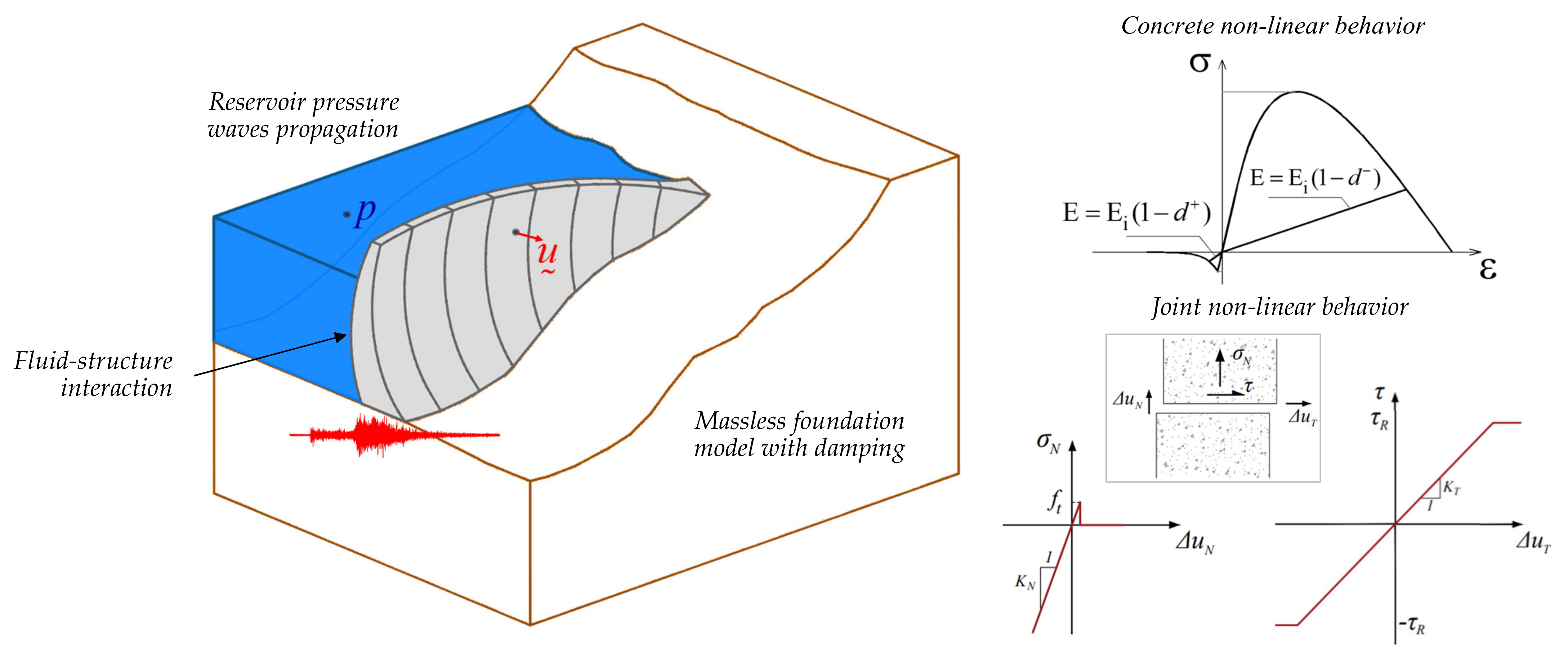
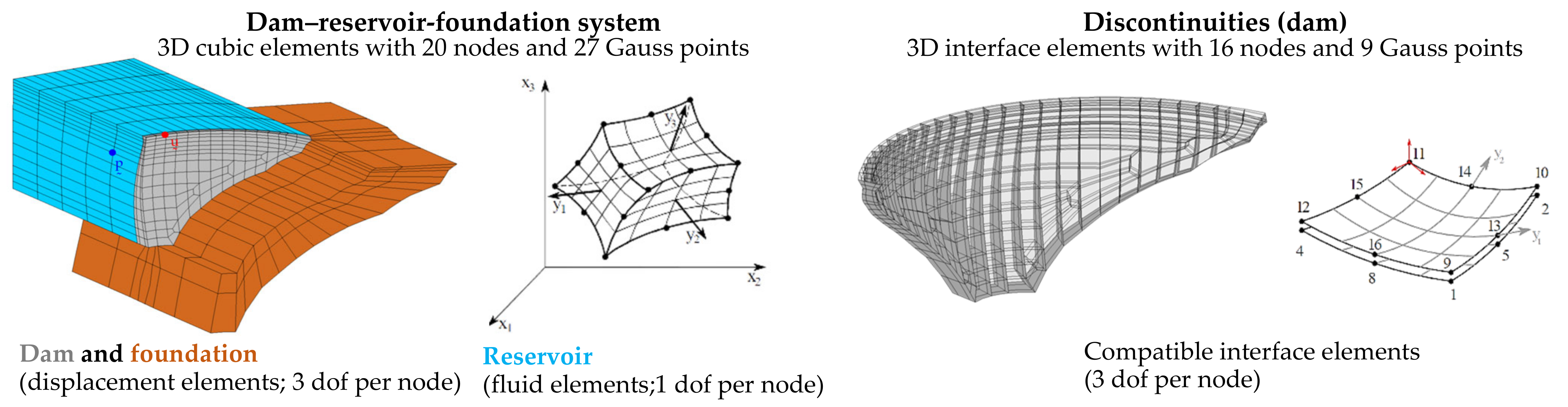
2.1. Models for Non-Linear Dynamic Analysis of Dam–Reservoir-Foundation Systems
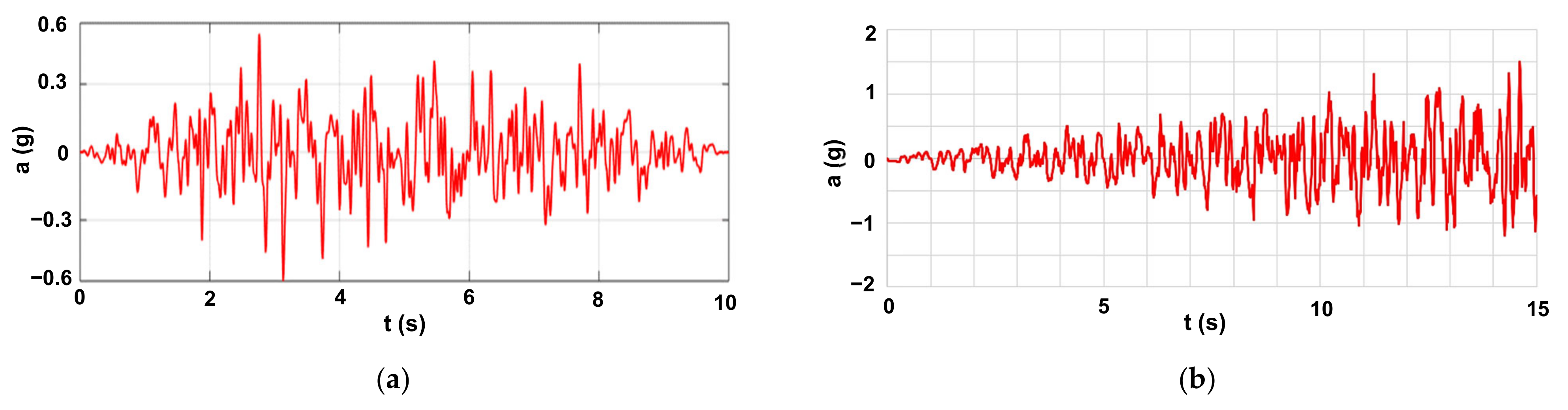
Large concrete dams are usually structures with unique and complex geometry, particularly in the case of arch dams, and they may have different types of discontinuities, including construction joints or concrete cracking. Furthermore, the dynamic behavior of dams is strongly influenced by the interaction with the reservoir and the foundation [33,34]. Therefore, for simulating the dynamic behavior of concrete dams it is essential to develop robust models of dam–reservoir–foundation systems (Figure 1), considering the specific features of the dam structure and multiple dynamic effects, such as dam–water interaction, pressure wave propagation in the reservoir domain, dam–foundation interaction, the behavior of the rock mass, and damping mechanisms, including viscous damping in the dam and radiation damping in the reservoir and foundation; these are factors that can have a significant influence in the overall seismic behavior of the dam [18,19].
To simulate the reservoir and dam–reservoir dynamic interaction, there is the classic added water mass model, using a displacement-based formulation for the dam and foundation and considering the reservoir mass effect based on the solution proposed by Westergaard [35]. Although simple and efficient, this model neglects water compressibility and hydrodynamic effects on curved and flexible dams [36,37], and the added mass effect is overestimated for arch dams [19]. Therefore, a better solution is to use a coupled model based on a finite element formulation for simulating the behavior of the solid (dam and foundation) and fluid (reservoir) domains [38]. In this case, it is common to consider a formulation in dispalcements for the solid, and in hydrodynamic pressures or in velocity potentials for the fluid, considering proper boundary conditions to simulate dam motion–water pressure coupling and the reservoir pressure wave propagation with radiation at the far-end boundary [38,39,40]. A coupled formulation in displacements and pressures was implemented in the finite element program DamDySSA.
Regarding the foundation behavior, the massless models hypothesize a deformable foundation block with a rigid boundary at the base, neglecting the wave propagation effects and radiation damping [41]. For massless models, the substructure method is usually employed to compute an elastic and massless substructure foundation block, considering an equivalent stiffness matrix condensed at the dam–rock interface [41,42]; the seismic input can be applied as uniform or spatially variable ground motion [43,44]. Alternatively, energy dissipating models consider the foundation mass and enable the simulation of wave propagation and radiation effects in the rock mass [34,45,46]. The seismic input can be obtained using equivalent force schemes, to generate the ground motion at the dam–foundation surface [47,48], or by performing deconvolution analysis and then using compression/shear waves propagating from the foundation base [40,45]. Neglecting the foundation inertia and damping can result in an overestimation of stresses in the dam body [45,49,50,51], if no additional damping source is considered. However, for substructure massless models, a damping matrix proportional to the foundation stiffness matrix can be introduced at the dam–rock interface, as considered in DamDySSA.
With regard to the seismic behavior of arch dams, under low intensity earthquakes, commonly measured on dams, low-amplitude movements are expected, and thus the numerical simulations can be carried out assuming linear-elastic behavior for concrete and considering that joints in the dam body remain closed [15,52,53,54]. On the other hand, under high intensity earthquakes, vibrations of greater amplitude and hence larger deformations may occur, resulting in the opening of the vertical contraction joints [55,56], and, at the same time, in high tensile and/or compressive stresses that might cause concrete cracking or crushing [57,58]. Therefore, for non-linear seismic analysis of arch dams, appropriate constitutive models should be used in order to simulate both the structural effects due to joint movements and the nonlinear behavior of concrete up to failure under tension and compression [59,60,61,62,63]. In DamDySSA, a robust formulation is implemented for non-linear seismic analysis, considering a non-linear joint model, to simulate opening/closing and sliding movements, and an isotropic constitutive damage model with softening and two independent damage variables for tension and compression.
Figure 1. Representation of an arch dam–reservoir-foundation system. Possible interaction effects for non-linear dynamic analysis.
Water 14 03835 g001

2.2. Ground Motion

For non-linear seismic analysis, carried out using time domain procedures, the seismic input is defined by means of acceleration time histories. Preferably, the earthquake ground motion should be represented by real accelerograms, recorded for site conditions similar to those of the dam to be analyzed [64]. Nevertheless, currently available records of strong earthquakes are not enough to cover the range of possible conditions, meaning that artificial acceleration time histories are needed [20]. Ideally, these accelerograms should be obtained based on the design ground motion parameters from specific seismic hazard studies conducted for the site of the dam to be analyzed.
Suitable acceleration time histories for dynamic response analysis can be generated from response spectra [65], considering specific features of the horizontal and vertical components and spatial variation effects (Figure 2a). Several methods have been developed for generating realistic seismic acceleration time histories, including the classic stochastic stationary procedure implemented in the computer program SIMQKE [66], the so-called Stochastic Method developed by Boore [67], the stochastic fault rupture and seismic wave propagation model developed by Carvalho [68], and the method for generating non-uniform ground motion using transfer functions proposed by Alves [47]. A different approach that has been gaining popularity in dam engineering is to consider endurance time excitation functions (ETEFs), developed by Estekanchi [69] and later optimized [70,71], which enable the generation of artificial intensifying acceleration time histories (Figure 2b) for ETA-based procedures.
Generated acceleration time histories, especially from ETEFs, may be quite different from acceleration records of real earthquakes, as they are models of the seismic load. Even so, by applying appropriate methods of analysis, the use of generated accelerograms as the seismic inputs in advanced numerical models of dam–reservoir–foundation systems will lead to a safe seismic design and to an adequate seismic safety assessment, which is essentially the main goal [72].
Figure 2. Seismic acceleration time histories: (a) design spectrum compatible generated acceleration time history; (b) intensifying dynamic excitation produced based on an ETEF.
Water 14 03835 g002

2.3. Methods of Analysis

The studies for seismic safety assessment of dams are usually conducted by performing multiple time history seismic analyses, using appropriate acceleration time histories, to simulate both common service scenarios and failure scenarios. The seismic response analyses can be carried out using one or multiple (with distinct frequency content) generated accelerograms, which are scaled to obtain seismic loads with various peak ground accelerations, corresponding to weaker or stronger ground motions. This methodology is according to the principals of Incremental Dynamic Analysis [73], and it has allowed researchers to obtain valuable results and draw assertive conclusions on the seismic capacity of large concrete dams; several application examples can be found in studies for gravity dams [61,74] and arch dams [75,76]. The obvious disadvantage is the need to conduct multiple calculations for different seismic excitation levels, resulting in longer calculation times to investigate different scenarios, particularly if non-linear analyses are required.
Another approach that has been used more frequently over the past decade is to evaluate the seismic capacity of concrete dams based on ETA [23,24,25,26,27,28,29], which is essentially a seismic analysis pushover procedure for seismic performance assessment under a pre-designed intensifying dynamic excitation. The aim of ETA is to subject the dam to dynamic vibrations from a low excitation level, where the structural response is within the linear domain, to medium excitation level, as structural non-linearities start to occur, and finally to a high excitation level, ultimately causing dam failure. Therefore, the evaluation of the seismic performance of the dam is performed in a single time history analysis, by controlling the response in multiple time steps along the process, considering one or several engineering demand parameters [24,29]. The ETA-based approach enables a good assessment of the seismic capacity of dams, and it is also highly efficient when compared to the traditional approach, as it significantly reduces computational demands. ETA procedures may also be of great use, e.g., for dynamic shape optimization [28].

2.4. Seismic Design and Performance Criteria

The general guidelines for seismic analysis, design and safety assessment are documented in bulletins [20] from the Committee on Seismic Aspects of Dam Design of ICOLD, as well as in the specific regulations of the National Commissions on Large Dams of its various member countries. In what concerns methods of analysis, it is possible to adopt simplified evaluation procedures based on linear seismic analysis for seismic performance evaluation. However, according to modern performance criteria, structural non-linearities are acceptable to a certain extent under severe earthquake levels. Thus, in current practice, non-linear seismic analysis procedures are considered, enabling researchers to investigate the non-linear structural behavior of dams towards collapse. With respect to the selection of seismic parameters for large dams [20], there are two main levels to be considered for seismic design and safety assessment: the Operating Basis Earthquake (OBE) and the Safety Evaluation Earthquake (SEE).
The OBE is the earthquake that may be expected to occur during the lifetime of the dam, with a minimum return period of 145 years (probability of occurrence of about 50% during a service life of 100 years). The OBE indicates an earthquake level under which significant damage or loss of service must not occur. The seismic performance criteria for the OBE can be verified based on linear-elastic dynamic analyses, by evaluating stresses and deformations, or through rigid body sliding and overturning stability analysis. For example, these types of verifications were conducted for the case of Luzzone Dam, in the scope of an ICOLD International Benchmark Workshop [77,78].
The SEE is the governing earthquake event for seismic design and safety assessment of the dam and safety-relevant components. The SEE can be taken as the Maximum Credible Earthquake (MCE), which is expected to induce the largest ground motion at the dam site, considering the seismic history and seismotectonic setup in the dam region, or as the Maximum Design Earthquake (MDE), with a return period of 10,000 years, using suitable ground motion parameters. Under the SEE, structural damage is acceptable to a certain extent, however the dam must resist without (a) structural integrity being compromised or (b) uncontrolled release of the reservoir, to avoid flooding in the downstream region. The performance criteria assessment under the SEE requires non-linear dynamic analysis methods, in order to investigate the main failure modes. For example, for arch dams, these failure modes include concrete crushing in key areas, under high compressive arch stresses, leading to the loss of bearing capacity in the arch direction, and the local sliding or overturning stability of blocks at the crest, due to large movements in the upstream direction; required modeling results may include inelastic deformations and joint movements, stresses, and tensile and compressive damages.

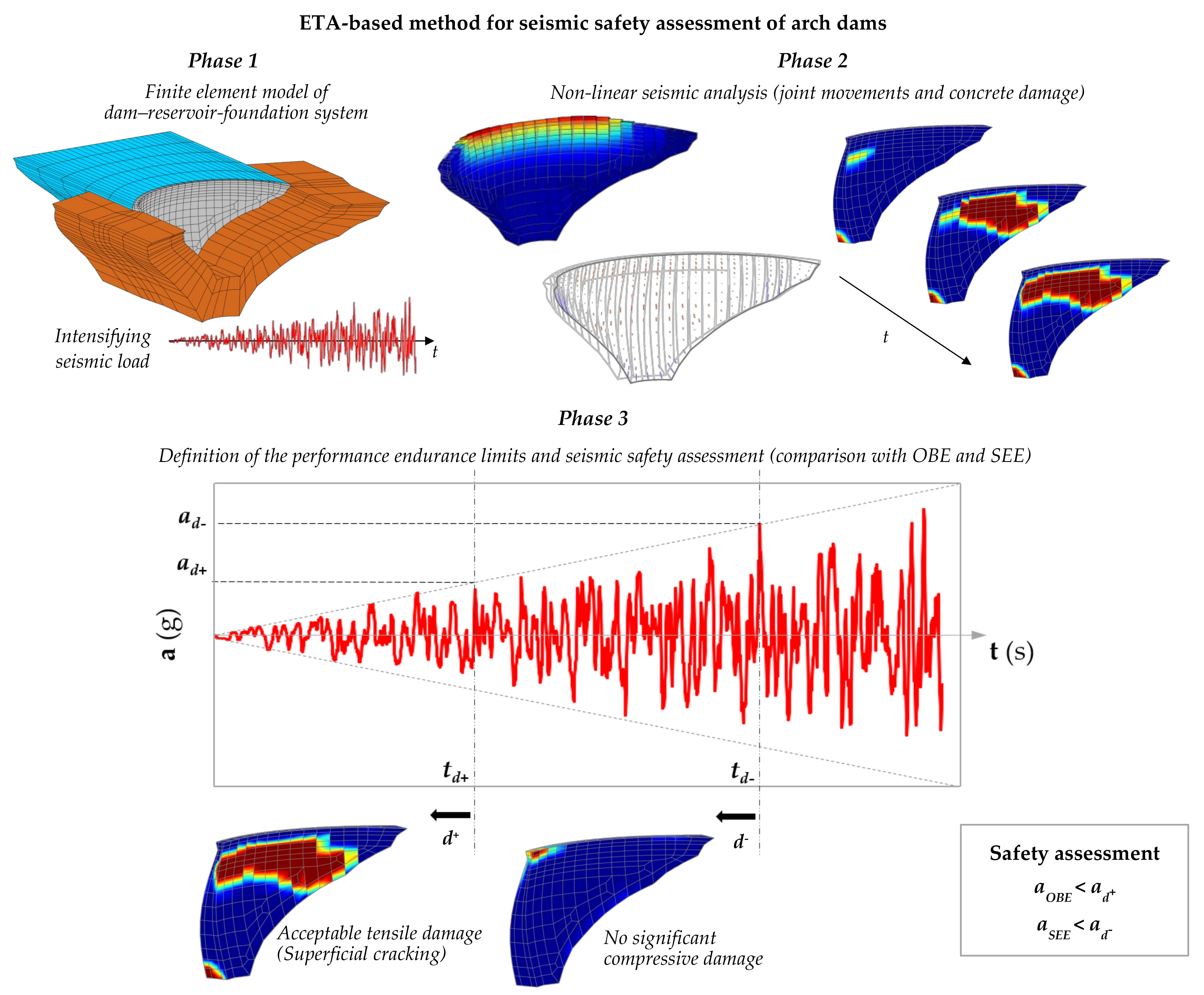
3. ETA-Based Method for Seismic Safety Assessment of Arch Dams

This paper presents a methodology for seismic safety assessment of arch dams based on ETA, using tensile and compressive damage results obtained in non-linear seismic simulations that consider the effects due to joint opening/sliding movements and the concrete non-linear behavior (see Section 4 about the program DamDySSA). The proposed approach for evaluating the seismic performance of the dam consists in an intuitive analysis, carried out by controlling the evolution of the damage state of the dam, considering appropriate performance criteria.
The main goal is to determine two endurance limits, one associated with tensile damage (t+; ad+) and the other with compressive damage (t; ad), which correspond to the duration or the respective acceleration level of an intensifying seismic load that the dam can withstand without presenting unacceptable levels of damage. In practice, the endurance limits are determined for two excitation levels, ad+ and ad, which correspond to the maximum acceleration values of the intensifying seismic action that originate acceptable damage states according to specific criteria defined for tensile, and compressive damage, respectively. In this way, it is expected for concrete cracking under tensions to become excessive after ad+ (repair interventions required), and for compressive damages to increase until concrete crushing occurs in key areas of the dam after ad (collapse scenario).
The adopted performance criteria are related to the extent of concrete damage on the dam body, with a view towards meeting the requirements defined for large dams under the OBE and the SEE in the current seismic design and safety guidelines [20]. Essentially, in terms of tensile damage, the occurrence of concrete cracking in significant areas of the upstream and/or downstream surfaces of the dam is considered unacceptable, particularly if there is cracking propagation across the thickness of the cantilevers, since this damage state could affect the structural integrity of the dam and require repair interventions—this scenario would not meet the dam safety requirements for the OBE. As for compressive damage, the occurrence of concrete crushing caused by compressive damage in key areas of the dam, e.g., in the upper blocks of the main cantilevers, is considered unacceptable, namely if there is propagation within these blocks, as this scenario could ultimately result in collapse and hence in an uncontrolled release of water from the reservoir—this would not comply with the dam safety requirements under SEE levels.
Finally, with the proposed approach, the seismic performance of the dam in relation to both earthquake levels is efficiently evaluated based on a single time history analysis, by comparing the acceleration limits for tensile and compressive damage with the peak ground accelerations prescribed for the Operating Basis Earthquake (OBE) and the Safety Evaluation Earthquake (SEE) of the dam site. In summary, the structural safety of the dam under seismic loads is ensured for the OBE, if aOBE < ad+, and for the SEE, if aSEE < ad.
The application of this method includes essentially three phases (Figure 3), namely:
  • Phase 1: Development of the 3D finite element model of the dam–reservoir–foundation system and generation the intensifying seismic load.
  • Phase 2: Perform the non-linear seismic calculations and output the non-linear response results in multiple time steps (response time histories, deformed shapes with joint movements, principal stresses fields, tensile and compressive damage).
  • Phase 3: Estimation of the performance endurance limits and comparison with reference ground motion parameters (OBE and SEE) for the seismic safety assessment.
Figure 3. Schematic representation of the proposed methodology for seismic safety assessment of dams based on ETA.
Water 14 03835 g003

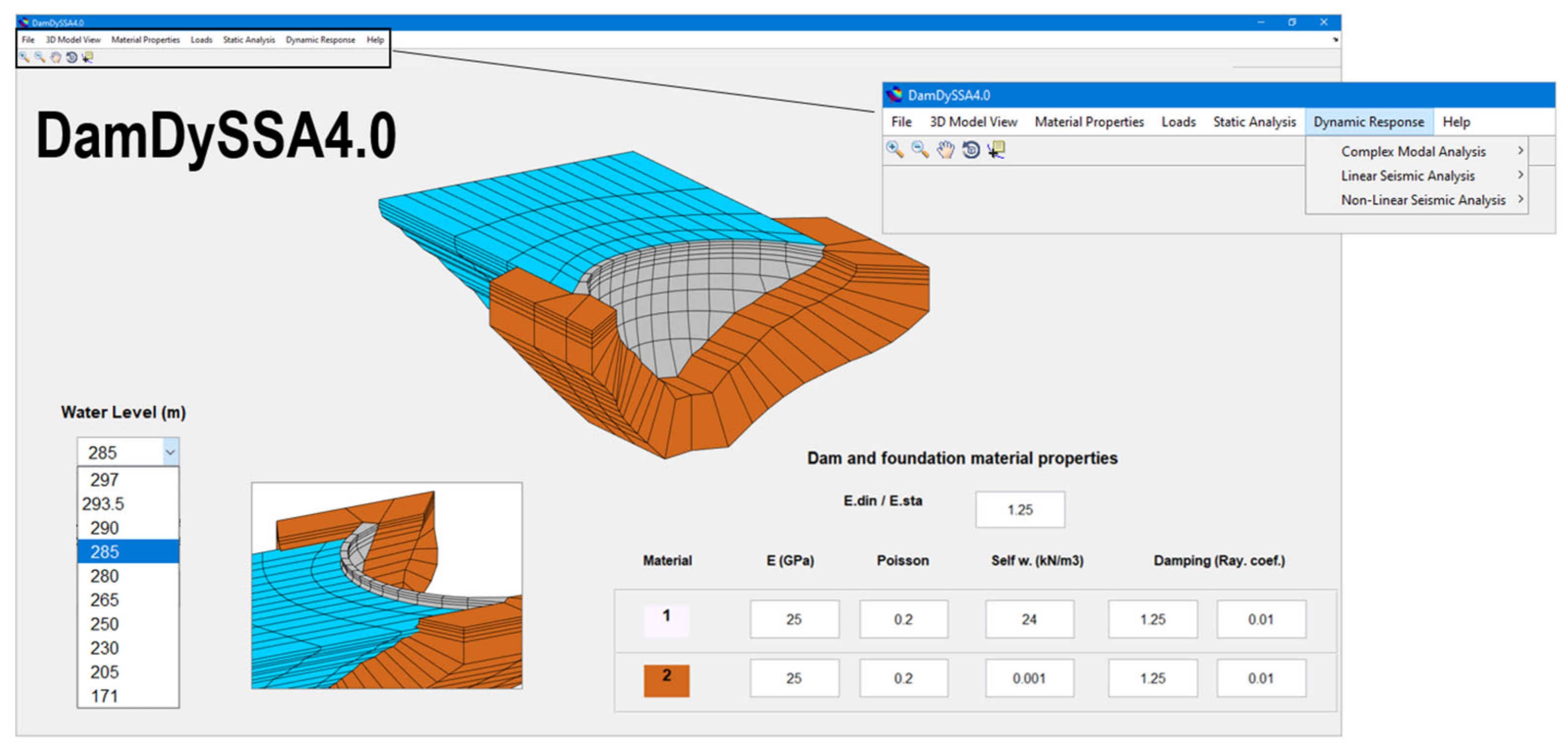
4. Used Finite Element Program (DamDySSA)

DamDySSA is a 3D finite element program for dynamic analysis of concrete dam–reservoir–foundation systems. Several years in development in LNEC, the latest version of the program includes calculation modules for modal analysis, linear seismic analysis, and non-linear seismic analysis [62]. Figure 4 shows the graphical user interface designed for the program in MATLAB. The coupled finite element formulation and the numerical method for non-linear seismic analysis are summarized in the following sub-sections.

4.1. Dynamic Behavior of the Dam–Reservoir-Foundation System: Finite Element Formulation

The dynamic behavior of the dam–reservoir–foundation system is simulated based on a coupled model in displacements (dam–foundation) and in hydrodynamic pressures (reservoir) [38]. Specific boundary conditions are prescribed at the main interfaces of the solid-fluid system, to consider dam–water dynamic interaction, the propagation of pressure waves in water with radiation at the far end of the reservoir, and the reservoir free surface effect [79]. In DamDySSA, a true coupled approach is adopted to solve the dynamic problem without separating the solid and fluid domain equations [62]. Therefore, the finite element equation of the dam–reservoir–foundation system is simply written
M ¯   q ˜ ¨ + C ¯   q ˜ ˙ + K ¯   q ˜ = F ˜ ,   q ˜ = u ˜ p ˜
where M ¯ , C ¯ and K ¯ are the global mass, damping and stiffness matrices, F ˜ = F ˜ ( t ) is the global nodal force vector, and q ¯ = q ¯ ( t ) is the coupled unknown vector. These coupled variables are defined as follows
M ¯ = m ¯ 0 ¯ ρ w Q ¯ T S ¯ ; C ¯ = c ¯ 0 ¯ 0 ¯ R ¯ ; K ¯ = k ¯ Q ¯ 0 ¯ H ¯ ; F ˜ = F ˜ s F ˜ w
where u ˜ = u ˜ ( t ) is the displacements vector for the dam nodes (three degrees of freedom for each node), while p = p ( t ) is the hydrodynamic pressures vector for the reservoir nodes (each with a single pressure degree of freedom). The mass, damping and stiffness matrices are m ¯ , c ¯ and k ¯ , for the solid domain, and S ¯ , R ¯ and H ¯ , for the fluid domain; the coupling matrix for water pressure–structure motion coupling is Q ¯ . The nodal force vectors in the solid and fluid domain are F ˜ s = F ˜ s ( t ) and F ˜ w = F ˜ w ( t ) , respectively; the forces in the dam may include the dam self-weight, the hydrostatic pressure on the upstream face, and the dynamic loads. Generalized damping is assumed, with natural viscous damping calculated element by element in the solid domain and energy dissipation due to radiation in the reservoir domain. The substructure method [41] is used to model the foundation block as an elastic and massless substructure, considering equivalent stiffness and damping components incorporated in the dam–rock interface; consequently, the seismic input is applied directly at the dam base, assuming uniform ground motion.
In this program, the dam–reservoir-foundation system is discretized using solid hexahedral finite elements with 20 nodes; these are isoparametric elements, and integration is achieved with 2nd degree interpolation functions and 27 Gauss points. The main discontinuities, e.g., dam–foundation interface, joints, or cracks, are discretized using compatible interface elements with 16 nodes and 9 integration Gauss points (Figure 5).

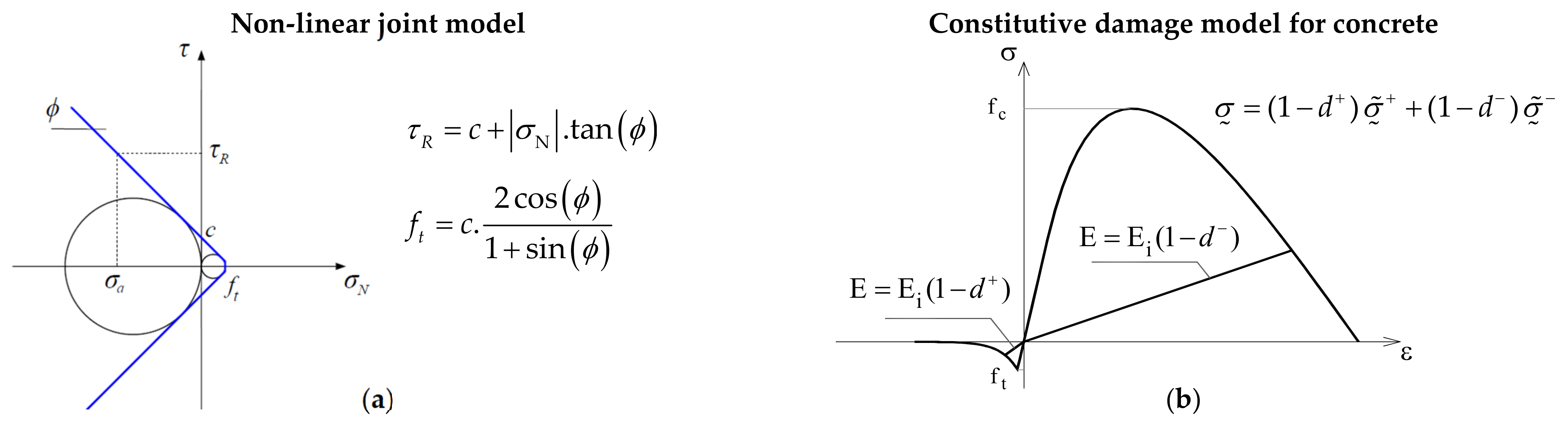
4.2. Non-Linear Time-Stepping Method for Non-Linear Seismic Analysis

The non-linear seismic response of the dam–reservoir–foundation system is calculated using a non-linear time-stepping method, considering both the structural effects due to the joint movements and the nonlinear behavior of concrete with softening under tension and compression [62]. The implemented method combines a time-stepping formulation, based on the application of the principles of the Newmark method [80], to the coupled dynamic problem, and a stress-transfer iterative method [81] to simulate non-linear dam behavior within each time step t+Δt. The goal is to solve the coupled dynamic equation in time domain
M ¯   q ˜ ¨ t + Δ t + C ¯   q ˜ ˙ t + Δ t + K ¯   q ˜ t + Δ t = F ˜ t + Δ t + Ψ ˜ t + Δ t
where Ψ ˜ is the vector of unbalanced forces, which is introduced in the problem to reproduce the stress redistribution process that takes place as structural non-linear behavior progresses.
In DamDySSA, the stress-transfer iterative process is conducted in each time step t+Δt, being divided into two iterative sub-processes: the first, to simulate the effects due to joint movements, and the second, to model the concrete behavior up to failure under tension and compression [62]. Therefore, the unbalanced forces that arise in the iterative process are associated with the unbalanced stresses due to joint and concrete non-linear behavior. The unbalanced stresses are computed as the difference between the installed stresses and the material strength, considering the following constitutive models (Figure 6). The non-linear joint behavior is simulated using a constitutive model based on the Mohr–Coulomb failure criterion (Figure 6a), with or without cohesion, and considering appropriate normal/shear stress-displacement laws to account for opening/closing and sliding movements [55,56], and (ii) the concrete behavior up to failure is reproduced using a 3D isotropic damage model with strain-softening and two independent scalar damage variables, d+ for damage under tension and d for damage under compression [82,83] (Figure 6b).

5. Results: Seismic Safety Assessment of Arch Dams

The ETA-based methodology presented in Section 3 is applied to evaluate the seismic performance of two large arch dams, namely the 132 m-high Cabril Dam (Portugal) and the 170 m-high Cahora Bassa Dam (Mozambique), and the non-linear seismic simulations are conducted using the program DamDySSA. Performance endurance limits associated with the evolution of tensile damage and compressive damage are determined and compared with peak ground accelerations for the OBE and the SEE. This section presents the case studies and the main results of this work.

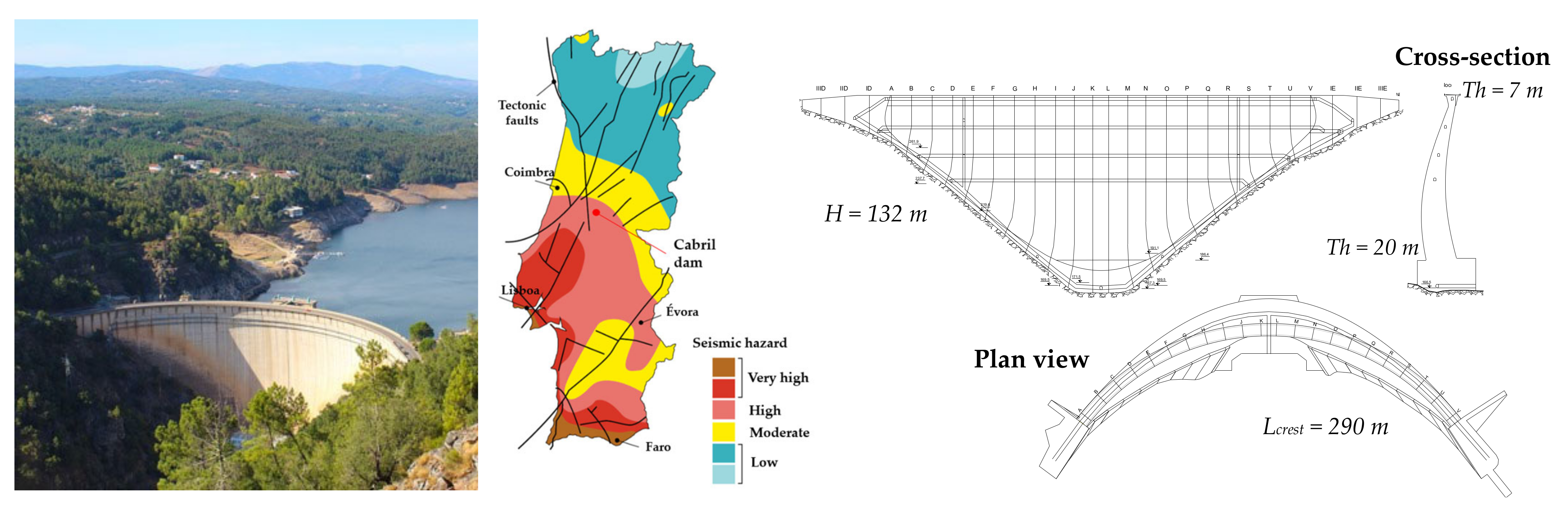
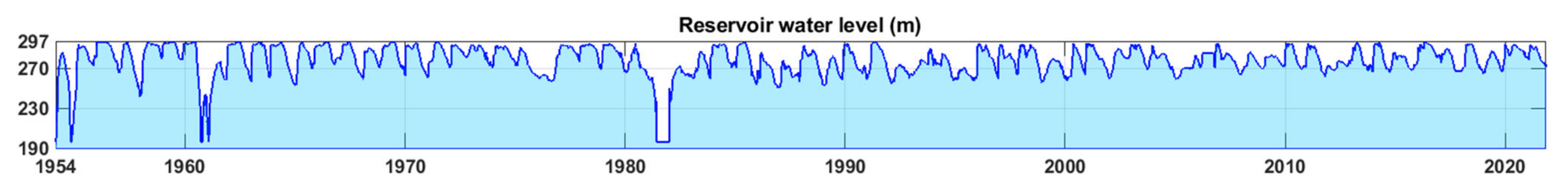
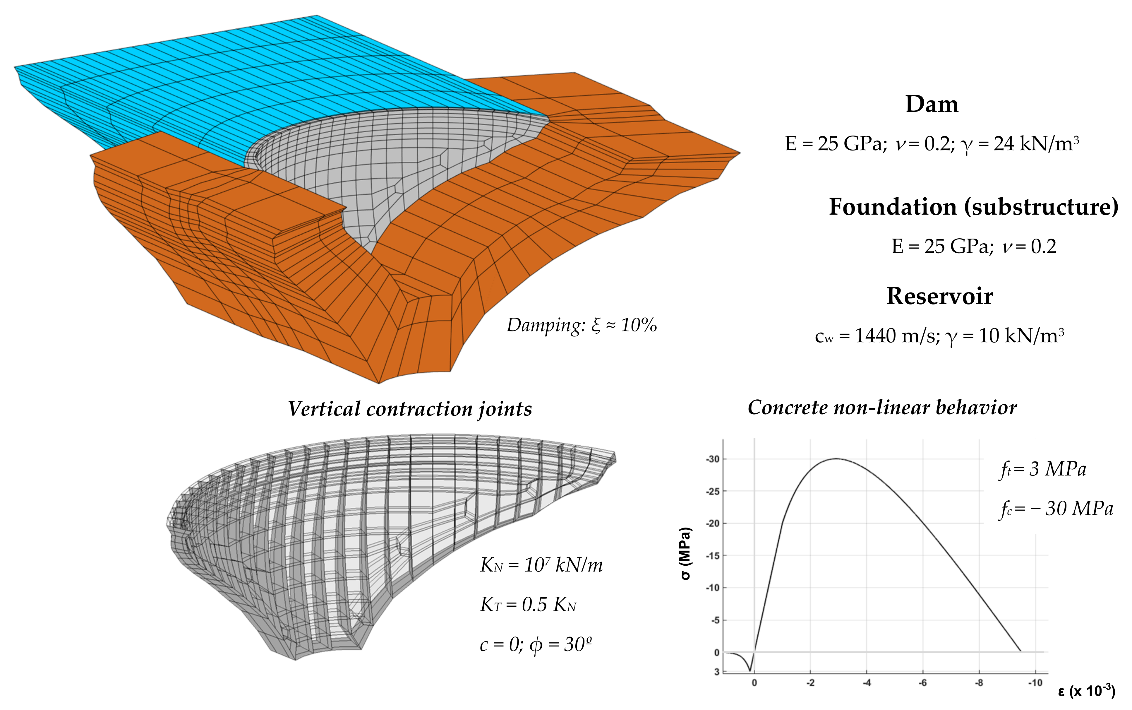
5.1. Case Study I: Cabril Dam (130 m-High)

5.1.1. Dam Description and Finite Element Mesh

The first case study is the iconic Cabril Dam (Figure 7), the highest dam in Portugal and an essential part of the country’s infrastructure, in operation since 1954. Cabril Dam is a 132 m-high double curvature arch dam, with a 290 m-long crest; this dam was designed with a unique geometry, as seen in the central cantilever, where the cross-section thickness varies between a maximum of 20 m, near the dam base, and a minimum of 4.5 m, about 7 m below the crest, increasing again to 7 m at the crest level. The dam was constructed on a good quality granite rock mass, and it impounds a reservoir with an area of around 20 million m2 and an effective storage of about 615 million m3. The reservoir level usually ranges from a minimum at el. 265 m to the normal level (NWL) at el. 295 m.
Located in the center of Portugal, Cabril Dam is integrated in a national region of high seismic risk, close to some active intraplate faults. A seismic risk study has not been conducted at the dam site as of yet, so there are no reference peak ground acceleration values for the OBE and the SEE. Nevertheless, a seismic hazard analysis was conducted for a site not very far from Cabril Dam, to the north-northwest, for which peak ground accelerations of 0.06 g (OBE) and 0.14 g (MDE) were prescribed [75]. Since Cabril Dam is in an area of higher seismic risk, similar or higher earthquake ground motion may be expected. Thus, peak ground accelerations of 0.1 g (OBE) and 0.2 g (MDE) have been assumed as reference for the seismic behavior studies to be conducted for Cabril Dam [62], in order to meet the recommendations of the Portuguese Standards for dam design [84].
Figure 8 shows the latest finite element mesh of the Cabril dam–reservoir–foundation system (with three elements in thickness in the dam body) and the main material properties. The dam concrete and foundation rock are assumed as isotropic materials, with Young’s modulus E = 25 GPa and Poisson’s ratio v = 0.2, while the water in the reservoir is considered a compressible fluid with a pressure wave propagation velocity cw = 1440 m/s. These material properties have been validated based on experimental results from vibration monitoring data under ambient/operational conditions and during seismic events [15,16,17]. For non-linear seismic analysis, all vertical contraction joints were incorporated into the dam mesh, using appropriate normal and shear stiffness values, null cohesion, and a 30° friction angle. The concrete constitutive damage law was adopted for all dam elements, with tensile strength ft = 3 MPa and compressive strength fc = −30 MPa.

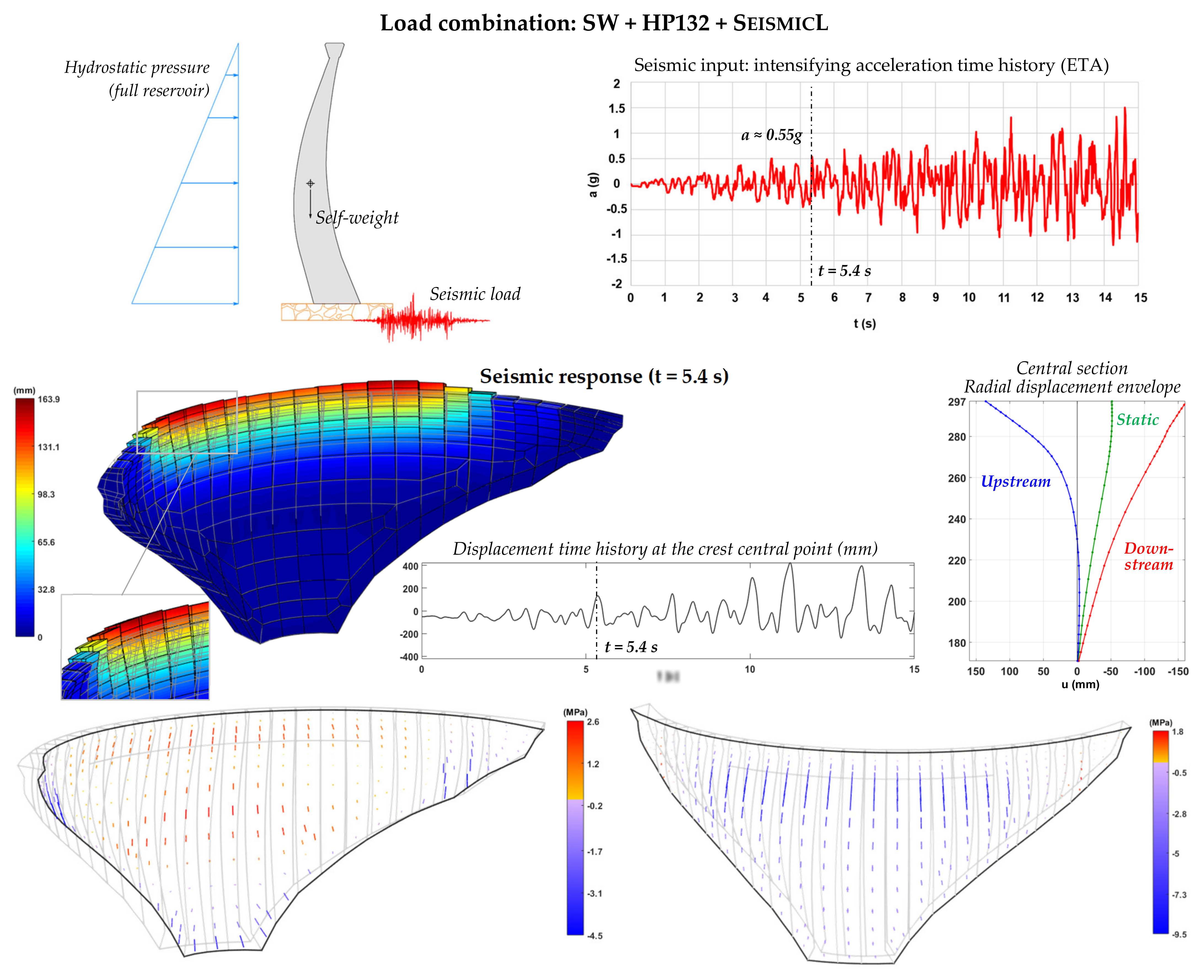
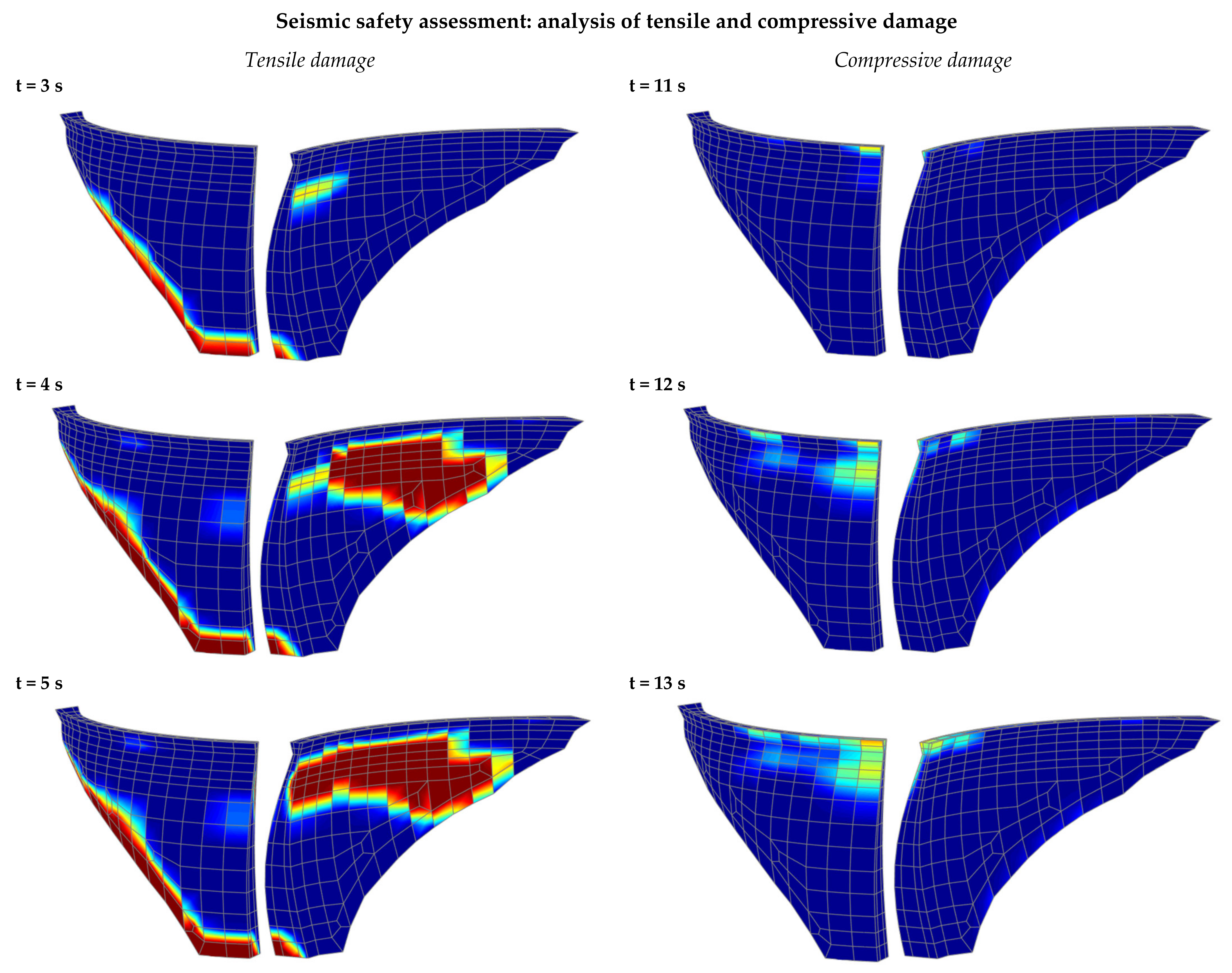
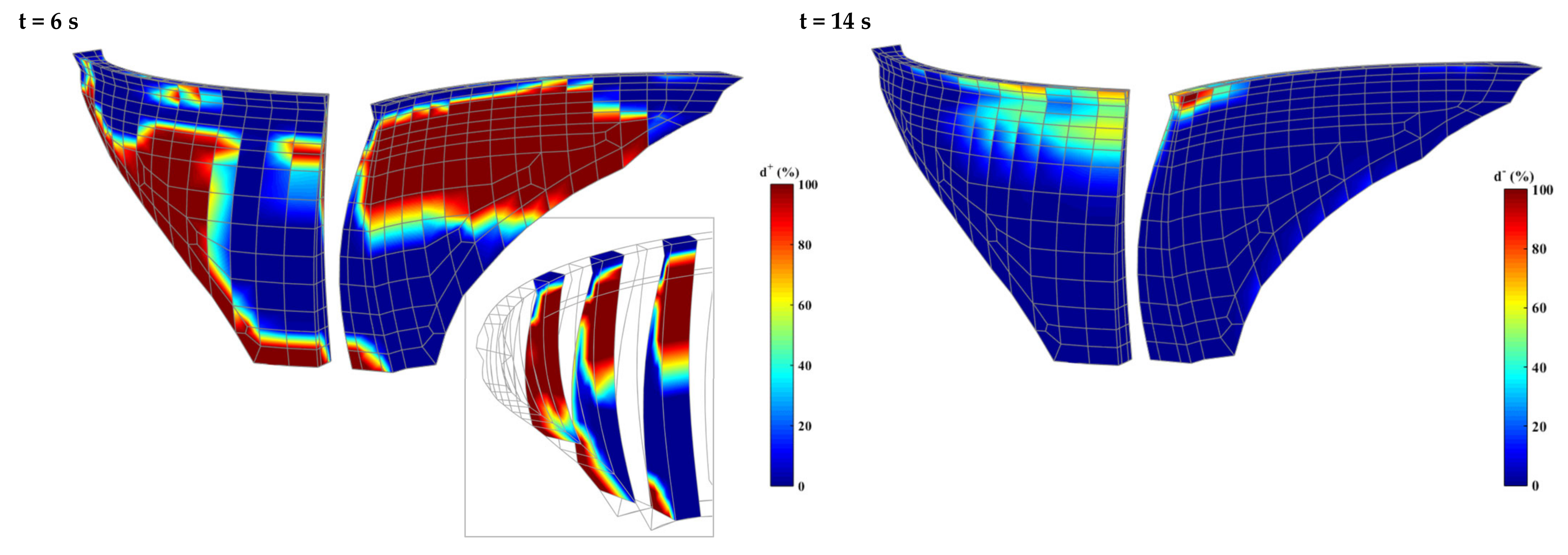
5.1.2. Non-Linear Seismic Analysis and Seismic Safety Assessment

For seismic safety assessment, the non-linear seismic behavior of Cabril Dam is simulated considering a dynamic load combination that includes the dam self-weight (SW), the hydrostatic pressure for full reservoir (HP132), and a seismic load (SeismicL) consisting of an acceleration time history designed for ETA, with accelerations increasing to about 1.5 g in 15 s (Figure 9). The non-linear response results show, when the seismic forces push the dam towards upstream, significant upstream displacements along the upper blocks and relative movements between the surfaces of the cantilevers. Furthermore, the opening of the vertical contraction joints causes a release of the arch tensions at the top of the dam, which prevents the occurrence of tensile damage. However, the subsequent stress redistribution process that takes place leads to an increase in vertical stresses along the height of the cantilevers, with vertical tensions that end up surpassing the concrete strength, causing concrete damage.
The evolution of the tensile and compressive damages obtained in the non-linear simulations under intensifying seismic accelerations is presented in Figure 10, aiming to make an overall assessment of the seismic performance of Cabril Dam and estimate the endurance limits according to the established performance criteria (recall Section 3).
Until t = 5 s, there is a gradual progression of tensile damage, and tensile failure ultimately occurs in several blocks along the upper part of the downstream face of the dam, and near the dam base, on the upstream side. Nevertheless, concrete cracking is mostly superficial and so this tensile damage state is considered acceptable. After that, between t = 5 s (a ≈ 0.5 g) and t = 6 s (a ≈ 0.6 g), there is an important increase in tensile damage at both upstream and downstream faces, with concrete cracking covering a significant part of the upper half of the dam, and already propagating from upstream to downstream in several blocks. This scenario could affect the structural integrity of the dam and thus require the interruption of normal operating conditions for repairs, hence failing to meet the performance criterion defined in the proposed method for the OBE excitation level. Accordingly, the endurance limit for tensile damage (t = 5 s) corresponds to an acceleration of 0.5 g, which is five times the value assumed as the OBE peak ground acceleration (0.1 g) at the dam site.
Figure 10. Seismic safety assessment of Cabril Dam: evolution of tensile and compressive damage for increasing acceleration levels.
Water 14 03835 g010aWater 14 03835 g010b
As for the compressive damage evolution, it is worth emphasizing that compressive damage began to arise only after t = 11 s (a ≈ 1.1 g), while the first occurrence of concrete compressive failure is reported at the top of the central cantilever, only after the dam was subjected to peak ground accelerations of about 1.3 g. Since the adopted performance criterion for compressive damage is based on the non-occurrence of concrete crushing with propagation across the blocks in key areas of the dam, which could induce collapse and uncontrolled release of water from the reservoir, the compressive endurance limit is at least 1.3 g, 6.5 times more than the peak ground acceleration considered for the MDE (0.2 g) for Cabril Dam, thus demonstrating its impressive resistant capacity.

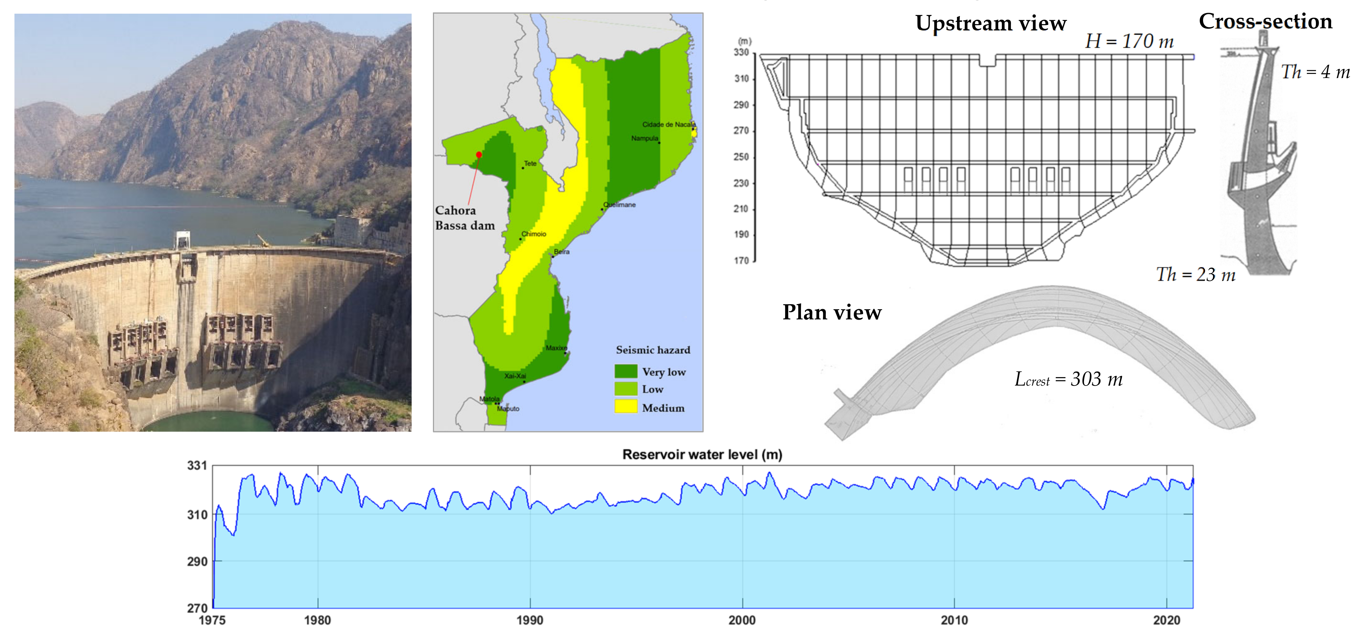
5.2. Case Study II: Cahora Bassa Dam (170 m-High)

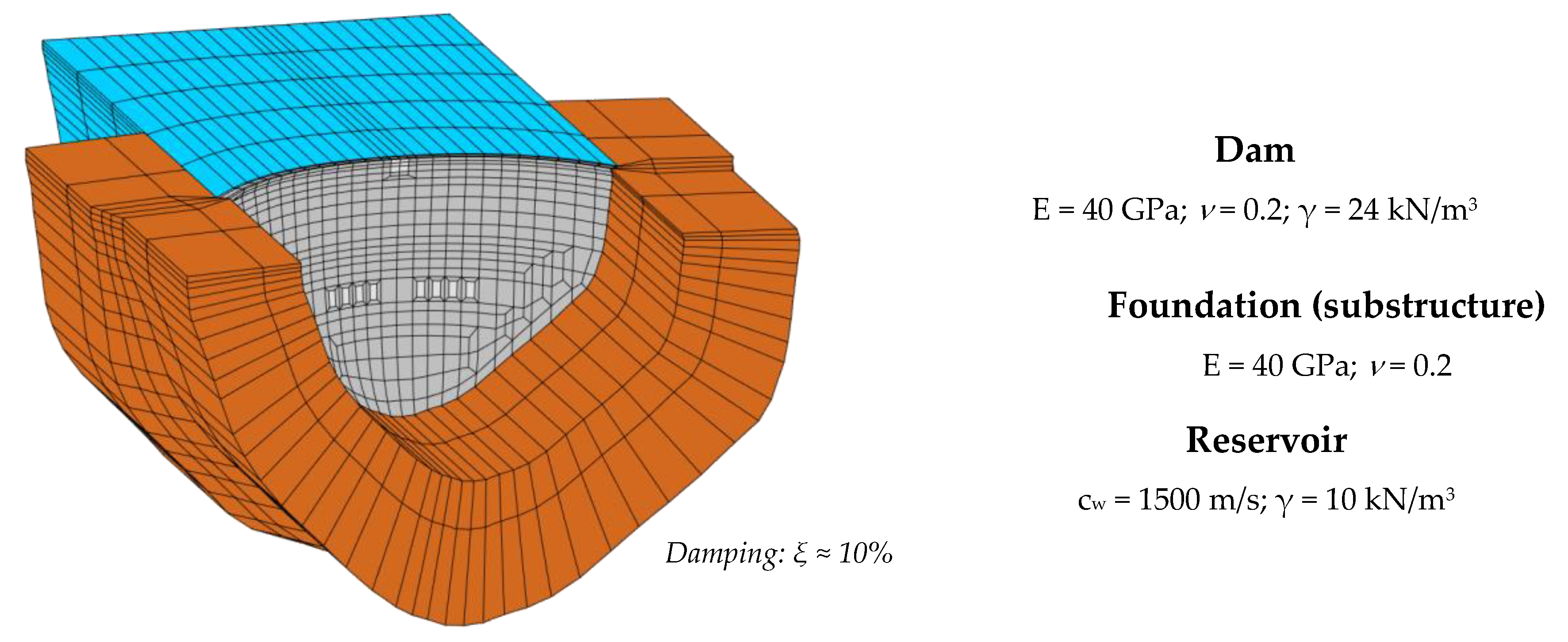
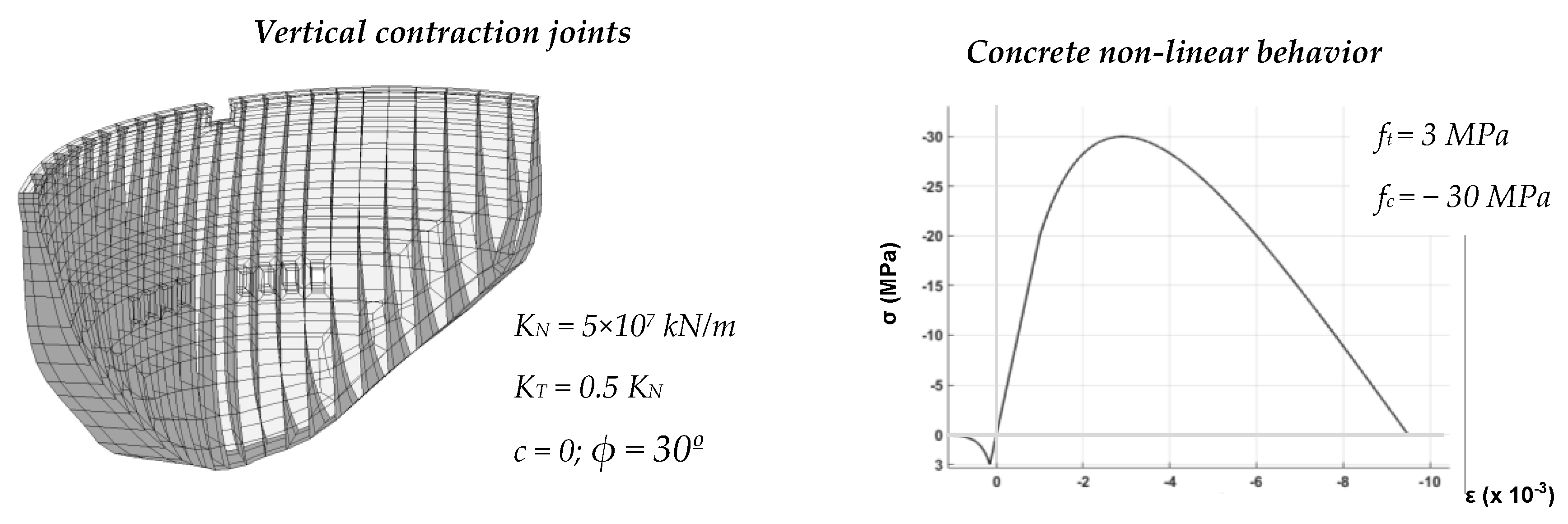
5.2.1. Dam Description and Finite Element Mesh

The second case study is the Cahora Bassa Dam (Figure 11), located on the Zambezi River, near Songo, in western Mozambique. Built from 1969 to 1974, it is one of the highest dams in the African continent. Cahora Bassa is a thin 170 m-high double curvature arch dam, with a 303 m-long arch at the crest, which presents a unique half-hollow shape. The thickness of the central cantilever ranges from a maximum of 23 m at the dam base, to about 4 m at the crest level. In addition, the dam has one control surface spillway and eight half-height spillways. The dam was constructed on a gneissic granite rock mass of very good quality, and it impounds Lake Cahora Bassa, which is 270 km long and 30 km wide at is widest point. The reservoir level does not usually present significant changes, varying between about el. 326 m and el. 320 m.
Cahora Bassa Dam is located in an earthquake hazard area, not far from the East African Rift system, which extends from the Red Sea to the Indic Ocean, across Mozambique, an active continental rift that is responsible for most earthquake events in Eastern Africa. According to a study on the seismic behavior of the dam [76], for seismic safety assessment the recommendations of the Portuguese Standards for dam design [84] can be followed. As such, the OBE and the MDE excitation levels must be considered for the evaluation of both regular and failure scenarios; the peak ground accelerations values to be used are those determined in the seismic hazard evaluation conducted for the Cahora Bassa Dam area [76], of 0.076 g (OBE) and 0.102 g (MDE).
Figure 11. Case study II: Cahora Bassa Dam. Location and seismic hazard zones. Upstream, cross-section and plan views. Variation of the reservoir level over time.
Water 14 03835 g011
The most recent finite element mesh of the Cahora Bassa dam–reservoir–foundation system is presented in Figure 12. The dam mesh, with three elements in thickness, replicates the real dam geometry quite well; still, in this version, the half-hollow crest shape and the geometry of the spillways are represented in a simplified way. The dam concrete and the foundation rock are considered to be isotropic materials, using Young’s modulus E = 40 GPa and Poisson’s ratio v = 0.2, while the reservoir water is simulated as a compressible fluid with a pressure wave propagation velocity cw = 1500 m/s. All material properties have been calibrated using dynamic experimental data, including modal parameters estimated from measured vibrations and seismic response results [15,16,17]. In order to simulate the non-linear structural response, vertical contraction joints were introduced in the dam body, considering calibrated stiffness values, null cohesion, and a 30° friction angle; the non-linear behavior of concrete is reproduced using the constitutive damage law with tensile strength ft = 3 MPa and compressive strength fc = −30 MPa for all dam elements.

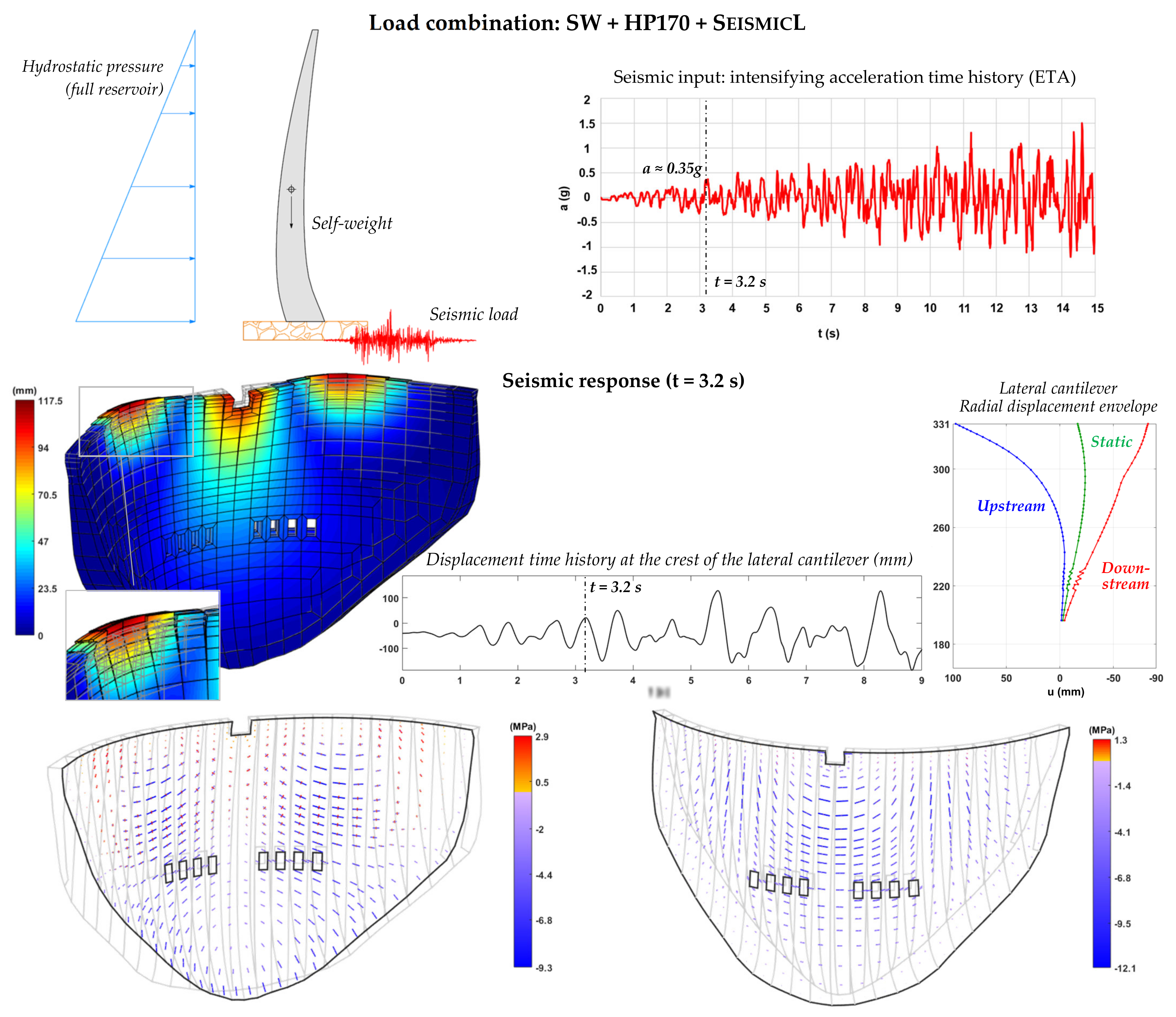
5.2.2. Non-Linear Seismic Analysis and Seismic Safety Assessment

In order to conduct the seismic safety evaluation of Cahora Bassa Dam, the non-linear seismic response (Figure 13) is computed for a load combination including the dam self-weight (SW), the hydrostatic pressure for full reservoir (HP170), and a seismic load (SeismicL) represented by the acceleration time history designed for ETA. The obtained non-linear response results enable us to see that, when the larger dynamic motions are in the upstream direction, the lateral cantilevers move towards upstream while the central cantilevers move in the opposite direction. In terms of structural effects due to the joint movements, similarly to the previous case study, the opening of the vertical contraction joints cause a reduction of the arch effect, and thus the arch tensions along the top of the dam are released, hence avoiding tensile damage at the upper blocks. However, the subsequent stress redistribution originates an increase in vertical stresses along the height of the dam cantilevers, and vertical tensions become greater than concrete tensile strength.
Lastly, the seismic safety assessment of Cahora Bassa Dam and the determination of performance endurance limits under the intensifying seismic excitation is conducted based on the evolution of the tensile and compressive damage (Figure 14), taking into account the established performance criteria (see Section 3).
The tensile damage evolution up to t = 5 s (a ≈ 0.5 g) shows that superficial concrete failure occurs near the upstream base and along the upper half of the downstream face of the dam. Since there is no sign of concrete cracking propagating across the thickness of the cantilevers, the resulting tensile damage state may be considered acceptable. However, past that there is a considerable propagation of concrete cracking over the upstream and downstream faces, and there are several blocks on most cantilevers where tensile failure has propagated through the entire section. Naturally, this scenario should be considered unacceptable, given the adopted criterion for the OBE. As such, the endurance limit related to tensile damage corresponds to an acceleration value of about 0.5 g, 6.5 times higher than the OBE peak ground acceleration (0.076 g) prescribed for Cahora Bassa Dam.
In what concerns the compressive damage evolution, until t = 6 s, there are no signs of damage due to compressions. After that point, however, compressive damage starts to increase progressively, specifically at the top of the lateral cantilevers, on the upstream face, and below the surface spillway, on the downstream face, until t = 9 s, when concrete crushing due to compressive failure has occurred from upstream to downstream in the blocks under the surface spillway. Bearing in mind the adopted performance criteria to meet the requirements under the SEE level, this scenario would not be acceptable as it could lead to local collapse and hence to the uncontrolled release of the reservoir. Thus, the endurance limit associated with compressive failure is set to around 0.8 g, about eight times the peak ground acceleration value of the MDE (0.102 g) for Cahora Bassa Dam.
Figure 14. Seismic safety assessment of Cahora Bassa Dam: evolution of tensile and compressive damage for increasing acceleration levels.
Water 14 03835 g014

5.3. Discussion

Section 5 provided the mains results of the studies conducted for the seismic safety assessment of two large arch dams, namely Cabril Dam and Cahora Bassa Dam, using the proposed ETA-based method (Section 3) and the finite element program DamDySSA (Section 4). Considering the adopted performance criteria, established to meet the requirements for the OBE and SEE, endurance limits were determined for both dams based on the evolution of tensile and compressive damage under intensifying seismic excitation.
For the case of Cabril Dam, the endurance limits were of 0.5 g for tensile damage and of at least 1.3 g for compressive damage: these values are, respectively, 5 and 6.5 times greater than the peak ground accelerations assumed for the OBE (0.1 g) and for the MDE (0.2 g). Therefore, the conducted seismic performance evaluation demonstrated the impressive resistant capacity of Cabril Dam under seismic loads. Moreover, the achieved results suggest that the seismic safety of the dam might be clearly verified in future studies, in case similar or even higher values than those assumed here are defined for the OBE and the MDE in seismic hazard studies carried out at the dam site.
As for Cahora Bassa Dam, the endurance limits were of about 0.5 g in terms of tensile damage, and around 0.8 g in what concerns compressive damage. These are acceleration values about 6.5 and 8 times greater, respectively, than the OBE (0.076 g) and MDE (0.102 g) peak ground accelerations prescribed for the Cahora Bassa Dam site. This seismic safety study showed that, despite being a thin 170 m-high arch dam, Cahora Bassa Dam performs very well under strong seismic loads, as both endurance limits were considerably greater than the values of the OBE and MDE peak ground accelerations.
Finally, the same tensile and compressive concrete strength values were considered for Cabril Dam and Cahora Bassa Dam, so it is worth comparing their seismic performance. On the one hand, Cahora Bassa Dam is taller and thinner than Cabril Dam, hence higher stresses tend to get installed. Thus, since compressions are considerably higher in Cahora Bassa Dam [55], the endurance limit associated with compressive damage is lower than for Cabril Dam. On the other hand, it was interesting to see that both arch dams presented similar tensile damage evolutions until t = 5 s, resulting in equal endurance limits; nevertheless, after that, the tensile damage progression was more severe for the case of Cahora Bassa Dam. Overall, by comparing the endurance limits with the prescribed values of the peak ground acceleration for the OBE and the SEE, both dams presented considerable safety factors. In the case Cahora Bassa Dam, located in an area of lower seismicity, the safety factors are slightly higher than for Cabril Dam.

6. Conclusions and Future Research

The seismic safety assessment is a fundamental issue for dam safety control, and therefore it is essential to develop suitable methods of analysis and robust models in order to analyze the seismic behavior of dams under strong earthquakes.
To contribute to this field, an ETA-based method for seismic safety assessment of arch dams, using tensile and compressive damage results from advanced non-linear seismic analyses considering joints and concrete non-linear behavior, was presented. In the ETA-based method, a new and intuitive approach was proposed for seismic performance evaluation, namely by controlling the evolution of the damage state of the dam. Considering suitable performance criteria, acceleration endurance limits are estimated based on the evolution of tensile and compressive damage, and then compared, respectively, with reference peak ground accelerations prescribed for the OBE and the SEE of the dam site. With this approach, it is possible to conduct the seismic safety assessment in relation to both earthquake levels (OBE and MDE) in an efficient manner, by conducting a single intensifying acceleration time history analysis.
An important innovation was also achieved in the finite element program DamDySSA, used to carry out the seismic analyses for this work. Several years under development in LNEC for dynamic analysis of dam–reservoir–foundation systems, the program is based on a coupled finite element formulation in displacements and pressures, and a robust formulation was recently implemented for non-linear seismic analysis, considering (a) non-linear joint behavior, using a constitutive model based on the Mohr–Coulomb failure criterion and using normal/shear stress-displacement laws for opening/closing and sliding movements, and (b) the concrete behavior up to failure, using an isotropic damage model with strain-softening and independent tensile and compressive scalar damage variables. A considerable investment was also made in programming the graphical outputs, to achieve realistic 3D representations of the damage in the dam body and hence facilitate the results analysis and interpretation.
The ETA-based method was then used to evaluate the seismic performance of the 132 m-high Cabril Dam (Portugal) and the 170 m-high Cahora Bassa Dam (Mozambique). The achieved results confirmed the potential of the proposed methodology for seismic safety assessment of concrete dams and showed that it enables a simple and intuitive analysis, which can be very beneficial for dam safety officers and dam owners. Therefore, the method can be used to support the seismic design and safety assessment of new dams or to conduct analyses for seismic safety reassessment of older dams that have been designed based on outdated methods and regulations; for example, a program for seismic safety reassessment of older large concrete dams of high potential risk could be carried out in Portugal and Mozambique, and the tools presented in this paper could prove useful. The proposed method can also be used to conduct seismic safety evaluations of dams for scenarios considering different reservoir water levels, distinct concrete strength properties, and using various intensifying seismic accelerogram with different frequency content.
In terms of future research, the proposed ETA-based methodology may be improved by including specific parameters that allow for a more objective quantification of the global damage state of the dam. In what concerns the program DamDySSA, it could be enhanced by implementing parallelization techniques, using GPU computing, in order to increase the computational efficiency of the non-linear analyses.

Author Contributions

Conceptualization, A.A. and S.O.; data curation: A.A., S.O. and P.M.; formal analysis: A.A. and S.O.; investigation: A.A., S.O., P.M., J.P. and R.R.; methodology: A.A. and S.O.; software: A.A. and S.O.; validation: A.A., S.O., P.M. and R.R.; visualization: A.A. and S.O.; writing—original draft: A.A. and S.O.; writing—review and editing: A.A., S.O., P.M., J.P., R.R. and E.C.; supervision: A.A. and S.O.; funding acquisition: S.O., P.M. and J.P.; project administration: A.A., S.O., P.M., J.P. and E.C.; resources: A.A., S.O., P.M., J.P. and E.C. All authors have read and agreed to the published version of the manuscript.

Funding

This research was funded by the Foundation for Science and Technology (FCT) in the framework of the project PTDC/ECI-EGC/5332/2020 - Seismic Monitoring and Structural Health of Large Concrete Dams (SSHM4Dams), involving LNEC, ISEL-IPL and IST-ID, and also within the scope of the project UIDB/04625/2020, which is under development at the Center for Research and Innovation in Civil Engineering for Sustainability (CERIS).

Institutional Review Board Statement

Not applicable.

Informed Consent Statement

Not applicable.

Data Availability Statement

The data presented in this study may be available on request from the corresponding author.

Acknowledgments

The authors thank Eletricidade de Portugal (EDP) and Hidroeléctrica de Cahora Bassa (HCB) for allowing the use of Cabril Dam and Cahora Bassa Dam, respectively, as case studies.

Conflicts of Interest

The authors declare no conflict of interest.

References

  1. ICOLD Bulletin 169: Global Climate Change, Dams, Reservoirs and Related Water Sources; Technical Committee Y, International Commission on Large Dams: Paris, France, 2016.
  2. ICOLD Bulletin Preprint 185: Challenges and Needs for Dams in the 21st Century. In Technical Committee on Global Climate Change and Dams, Reservoirs and the Associated Water Resources; International Commission on Large Dams: Paris, France, 2019.
  3. UNESCO. UN-Water United Nations World Water Development Report 2020: Water and Climate Change; United Nations Educational, Scientific, and Cultural Organization: Paris, France, 2020. [Google Scholar]
  4. ICOLD World Declaration on Dam Safety; International Commission on Large Dams: Porto, Portugal, 2019; pp. 36–40.
  5. IJHD World Atlas & Industry Guide; Aqua Media Int. Ltd.: Wallington, UK, 2021.
  6. Wieland, M.; Chen, H. Leassons Learnt from the Wenchuan Earthquake. Int. Water Power Dam Constr. 2009.
  7. Wieland, M. Features of Seismic Hazard in Large Dam Projects and Strong Motion Monitoring of Large Dams. Front. Archit. Civ. Eng. China 2010, 4, 56–64. [Google Scholar] [CrossRef]
  8. Wieland, M. Seismic Hazard and Seismic Design and Safety Aspects of Large Dam Projects. In Perspectives on European Earthquake Engineering and Seismology; Geotechnical, Geological and Earthquake Engineering; Ansal, A., Ed.; Springer: Cham, Switzerland, 2014; pp. 627–650. [Google Scholar]
  9. Wieland, M. Safety Aspects of Sustainable Storage Dams and Earthquake Safety of Existing Dams. Engineering 2016, 2, 325–331. [Google Scholar] [CrossRef] [Green Version]
  10. Wang, R.; Chen, L.; Zhang, C. Seismic Design of Xiluodu Ultra-High Arch Dam. Water Sci. Eng. 2018, 11, 288–301. [Google Scholar] [CrossRef]
  11. Wang, R. Key Technologies in the Design and Construction of 300 M Ultra-High Arch Dams. Engineering 2016, 2, 350–359. [Google Scholar] [CrossRef] [Green Version]
  12. Zhang, C.; Xu, Y.; Wang, G.; Jin, F. Non-Linear Seismic Response of Arch Dams with Contraction Joint Opening and Joint Reinforcements. Earthq. Eng. Struct. Dyn. 2000, 29, 1546–1566. [Google Scholar] [CrossRef]
  13. Zhang, C.; Xu, Y.; Jin, F.; Wang, G. Studies on Seismic Behaviour of Xiaowan Arch Dam and Earthquake Resistance Measures. In Proceedings of the 13th World Conference on Earthquake Engineering, Vancouver, BC, Canada, 1–6 August 2004. [Google Scholar]
  14. Darbre, G.R.; Schwager, M.V.; Panduri, R. Seismic Safety Evaluation of Large Dams in Switzerland: Lessons Learned. Int. Water Power Dam Constr. 2019, 70, 22–27. [Google Scholar]
  15. Alegre, A.; Carvalho, E.; Matsinhe, B.; Mendes, P.; Oliveira, S.; Proença, J. Monitoring Vibrations in Large Dams. In Proceedings of the HYDRO 2019—Concept to closure: Practical Steps, Porto, Portugal, 16–19 October 2019. [Google Scholar]
  16. Alegre, A.; Oliveira, S.; Carvalho, E.; Mendes, P.; Proença, J.; Matsinhe, B. Continuous Dynamic Monitoring of Large Arch Dams and Vibration-Based Damage Detection. In Proceedings of the HYDRO 2022—Roles of Hydro in the Global Recovery, Strasbourg, France, 25–27 April 2022. [Google Scholar]
  17. Oliveira, S.; Alegre, A.; Carvalho, E.; Mendes, P.; Proença, J. Seismic and Structural Health Monitoring Systems for Large Dams: Theoretical, Computational and Practical Innovations. Bull. Earthq. Eng. 2022, 20, 4483–4512. [Google Scholar] [CrossRef]
  18. Chopra, A.K. Earthquake Analysis of Arch Dams: Factors to Be Considered. J. Struct. Eng. 2012, 138, 205–214. [Google Scholar] [CrossRef] [Green Version]
  19. Chen, H. Seismic Safety of High Concrete Dams. Earthq. Eng. Eng. Vib. 2014, 13, 1–16. [Google Scholar] [CrossRef]
  20. ICOLD Bulletin 148: Selecting Seismic Parameters for Large Dams—Guidelines (Revision of Bulletin 72); Committee on Seismic Aspects of Dam Design, International Commission on Large Dams: Paris, France, 2016.
  21. ICOLD Bulletin 168: Recommendations for Operation, Maintenance and Rehabilitation; International Comission on Large Dams: Paris, France, 2017.
  22. ICOLD Bulletin 158: Dam Surveillance Guide; International Comission on Large Dams: Paris, France, 2018.
  23. Valamanesh, V.; Estekanchi, H.E.; Vafai, A.; Ghaemian, M. Application of the Endurance Time Method in Seismic Analysis of Concrete Gravity Dams. Sci. Iran. 2011, 18, 326–337. [Google Scholar] [CrossRef] [Green Version]
  24. Hariri-Ardebili, M.A.; Saouma, V.E.; Porter, K.A. Quantification of Seismic Potential Failure Modes in Concrete Dams. Earthq. Eng. Struct. Dyn. 2016, 45, 979–997. [Google Scholar] [CrossRef]
  25. Meghella, M.; Furgani, L. Application of Endurance Time Analysis Method to the NonLinear Seismic Analysis of Dams: Potentialities and Limitations. In Proceedings of the ICOLD 82nd Annual Meeting, Banff, AB, Canada, 4–5 October 2014. [Google Scholar]
  26. Hariri-Ardebili, M.A.; Mirzabozorg, H. Estimation of Probable Damages in Arch Dams Subjected to Strong Ground Motions Using Endurance Time Acceleration Functions. KSCE J. Civ. Eng. 2014, 18, 574–586. [Google Scholar] [CrossRef]
  27. Hariri-Ardebili, M.A.; Mirzabozorg, H.; Estekanchi, H.E. Nonlinear Seismic Assessment of Arch Dams and Investigation of Joint Behavior Using Endurance Time Analysis Method. Arab. J. Sci. Eng. 2014, 39, 3599–3615. [Google Scholar] [CrossRef]
  28. Abdollahi, A.; Amini, A.; Hariri-Ardebili, M.A. An Uncertainty-Aware Dynamic Shape Optimization Framework: Gravity Dam Design. Reliab. Eng. Syst. Saf. 2022, 222, 108402. [Google Scholar] [CrossRef]
  29. Hariri-Ardebili, M.A.; Furgani, L.; Meghella, M.; Saouma, V.E. A New Class of Seismic Damage and Performance Indices for Arch Dams via ETA Method. Eng. Struct. 2016, 110, 145–160. [Google Scholar] [CrossRef]
  30. Furgani, L.; Hariri-Ardebili, M.A.; Meghella, M.; Seyed-Kolbadi, S.M. On the Dynamic Capacity of Concrete Dams. Infrastructures 2019, 4, 57. [Google Scholar] [CrossRef] [Green Version]
  31. Hariri-Ardebili, M.; Mahdavi, G.; Abdollahi, A.; Amini, A. An RF-PCE Hybrid Surrogate Model for Sensitivity Analysis of Dams. Water 2021, 13, 302. [Google Scholar] [CrossRef]
  32. Segura, R.L.; Miquel, B.; Paultre, P.; Padgett, J.E. Accounting for Uncertainties in the Safety Assessment of Concrete Gravity Dams: A Probabilistic Approach with Sample Optimization. Water 2021, 13, 855. [Google Scholar] [CrossRef]
  33. Pedro, J.O.; Câmara, R. Coupled Models for Dynamic Analysis of Arch Dams. In Proceedings of the 8th European Conference on Earthquake Engineering, Lisbon, Portugal, 7–12 September 1986. [Google Scholar]
  34. Chopra, A.K.; Tan, H. Modelling Dam-Foundation Interaction in Analysis of Arch Dams. In Proceedings of the 10th World Conference on Earthquake Engineering, Madrid, Spain, 19–24 July 1992. [Google Scholar]
  35. Westergaard, H.M. Water Pressures on Dams during Earthquakes. Trans. Am. Soc. Civ. Eng. 1933, 98, 418–472. [Google Scholar] [CrossRef]
  36. Tiliouine, B.; Seghir, A. Fluid-Structure Models for Dynamic Studies of Dam-Water Systems. In Proceedings of the 11th European Conference on Earthquake Engineering, Paris, France, 6–11 September 1998. [Google Scholar]
  37. Fok, K.L.; Chopra, A.K. Hydrodynamic and Foundation Flexibility Effects in Earthquake Response of Arch Dams. J. Struct. Eng. 1986, 112, 1810–1828. [Google Scholar] [CrossRef]
  38. Zienkiewicz, O.C.; Bettess, P. Fluid-Structure Dynamic Interaction and Wave Forces. An Introduction to Numerical Treatment. An Introduction to Numerical Treatment. Int. J. Numer. Methods Eng. 1978, 13, 1–16. [Google Scholar] [CrossRef]
  39. Bouaanani, N.; Lu, F.Y. Assessment of Potential-Based Fluid Finite Elements for Seismic Analysis of Dam-Reservoir Systems. Comput. Struct. 2009, 87, 206–224. [Google Scholar] [CrossRef]
  40. Lokke, A.; Chopra, A.K. Direct Finite Element Method for Nonlinear Earthquake Analysis of 3-Dimensional Semi-Unbounded Dam–water-Foundation Rock Systems. Earthq. Eng. Struct. Dyn. 2018, 47, 1309–1328. [Google Scholar] [CrossRef] [Green Version]
  41. Clough, R.W. Non-Linear Mechanisms in the Seismic Response of Arch Dams. In Proceedings of the International Research Conference on Earthquake Engineering, Skopje, Yugoslavia, 30 June–3 July 1980. [Google Scholar]
  42. Fok, K.L.; Chopra, A.K. Earthquake Analysis of Arch Dams Including Dam-Water Interaction, Reservoir Boundary Absorption and Foundation Flexibility. Earthq. Eng. Struct. Dyn. 1986, 14, 155–184. [Google Scholar] [CrossRef]
  43. Wang, J.-T.; Chopra, A.K. Linear Analysis of Concrete Arch Dams Including Dam-Water-Foundation Rock Interaction Considering Spatially Varying Ground Motions. Earthq. Eng. Struct. Dyn. 2010, 39, 731–750. [Google Scholar] [CrossRef]
  44. Alves, S.W.; Hall, J.F. Generation of Spatially Nonuniform Ground Motion for Nonlinear Analysis of a Concrete Arch Dam. Earthq. Eng. Struct. Dyn. 2006, 35, 1139–1357. [Google Scholar] [CrossRef]
  45. Zhang, C.; Pan, J.; Wang, J.-T. Influence of Seismic Input Mechanisms and Radiation Damping on Arch Dam Response. Soil Dyn. Earthq. Eng. 2009, 29, 1282–1293. [Google Scholar]
  46. Dominguez, J.; Maeso, O. Model for the Seismic Analysis of Arch Dams Including Interaction Effects. In Proceedings of the 10th World Conference on Earthquake Engineering, Madrid, Spain, 19–24 July 1992. [Google Scholar]
  47. Alves, S.W. Nonlinear Analysis of Pacoima Dam with Spatially Non-Uniform Ground Motion. Ph.D. Thesis, California Institute of Technology, Pasadena, California, 2004. [Google Scholar]
  48. Wang, J.-T.; Lv, D.-D.; Jin, F.; Zhang, C. Earthquake Damage Analysis of Arch Dams Considering Dam–water–foundation Interaction. Soil Dyn. Earthq. Eng. 2013, 49, 64–74. [Google Scholar] [CrossRef]
  49. Mirzabozorg, H.; Kordzadeh, A.; Hariri-Ardebili, M.A. Seismic Response of Concrete Arch Dams Including Dam-Reservoir-Foundation Interaction Using Infinite Elements. Electron. J. Struct. Eng. 2012, 12, 63–73. [Google Scholar] [CrossRef]
  50. Hariri-Ardebili, M.A.; Mirzabozorg, H. A Comparative Study of Seismic Stability of Coupled Arch Dam-Foundation-Reservoir Systems Using Infinite Elements and Viscous Boundary Models. Int. J. Struct. Stab. Dyn. 2013, 13, 1350032. [Google Scholar] [CrossRef]
  51. Chen, D.-H.; Du, C.-B.; Yuan, J.-W.; Hong, Y.-W. An Investigation into the Influence of Damping on the Earthquake Response Analysis of a High Arch Dam. J. Earthq. Eng. 2012, 16, 329–349. [Google Scholar] [CrossRef]
  52. Robbe, E.; Kashiwayanagi, M.; Yamane, Y. Seismic Analyses of Concrete Dam, Comparison between Finite-Element Analyses and Seismic Records. In Proceedings of the 16th World Conference on Earthquake Engineering, Santiago, Chile, 9–13 January 2017. [Google Scholar]
  53. Chopra, A.K.; Wang, J.-T. Earthquake Response of Arch Dams to Spatially Varying Ground Motion. Earthq. Eng. Struct. Dyn. 2010, 39, 887–906. [Google Scholar] [CrossRef]
  54. Proulx, J.; Darbre, G.R. Earthquake Response of Large Arch Dams Observational Evidence and Numerical Modelling. In Proceedings of the 14th World Conference on Earthquake Engineering, Beijing, China, 12–17 October 2008. [Google Scholar]
  55. Fenves, G.L.; Mojtahedi, S.; Reimer, R.B. Effect of Contraction Joints on Earthquake Response of an Arch Dam. J. Struct. Eng. 1992, 118, 1039–1055. [Google Scholar] [CrossRef]
  56. Niwa, A.; Clough, R.W. Non-Linear Seismic Response of Arch Dams. Earthq. Eng. Struct. Dyn. 1982, 10, 267–281. [Google Scholar] [CrossRef]
  57. Cervera, M.; Oliver, J.; Faria, R. Seismic Evaluation of Concrete Dams via Continuum Damage Models. Earthq. Eng. Struct. Dyn. 1995, 24, 1225–1245. [Google Scholar] [CrossRef]
  58. Valliappan, S.; Yazdchi, M.; Khalili, N. Seismic Analysis of Arch Dams—A Continuum Damage Mechanics Approach. Int. J. Numer. Methods Eng. 1999, 45, 1695–1724. [Google Scholar] [CrossRef]
  59. Hariri-Ardebili, M.A.; Mirzabozorg, H. Seismic Performance Evaluation and Analysis of Major Arch Dams Considering Material and Joint Nonlinearity Effects. ISRN Civ. Eng. 2012, 2012, 681350. [Google Scholar] [CrossRef] [Green Version]
  60. Wang, J.-T.; Zhang, C.; Jin, F. Nonlinear Earthquake Analysis of High Arch Dam-Water-Foundation Rock Systems. Earthq. Eng. Struct. Dyn. 2012, 41, 1157–1176. [Google Scholar] [CrossRef]
  61. Pan, J.; Xu, Y.; Jin, F. Seismic Performance Assessment of Arch Dams Using Incremental Nonlinear Dynamic Analysis. Eur. J. Environ. Civ. Eng. 2015, 19, 305–326. [Google Scholar] [CrossRef]
  62. Alegre, A. Modelling and Monitoring the Dynamic Behaviour of Concrete Dams. Modal Analysis and Seismic Response. Ph.D. Thesis, Instituto Superior Técnico, University of Lisbon, Lisboa, Portugal, 2021. [Google Scholar]
  63. Goldgruber, M. Non-Linear Seismic Modelling of Concrete Dams. Ph.D. Thesis, Graz University of Technology, Graz, Austria, 2015. [Google Scholar]
  64. Bommer, J.; Acevedo, A.B. The Use of Real Earthquake Accelerograms as Input to Dynamic Analysis. J. Earthq. Eng. 2004, 8, 43–91. [Google Scholar] [CrossRef]
  65. Clough, R.W.; Penzien, J. Dynamics of Structures, 3rd ed.; Computers & Structures, Inc.: Berkeley, CA, USA, 2003. [Google Scholar]
  66. Gasparini, D.A.; Vanmarcke, E.H. Simulated Earthquake Motions Compatible with Prescribed Response Spectra. Research Report R76-4; Dept. of Civil Engineering, Massachusetts Institute of Technology: Cambridge, MA, USA, 1976. [Google Scholar]
  67. Boore, D.M. Simulation of Ground Motion Using the Stochastic Method. Pure Appl. Geophys. 2003, 160, 636–676. [Google Scholar] [CrossRef] [Green Version]
  68. Carvalho, A. Modelação Estocástica Da Acção Sísmica Em Portugal Continental [Stochastic Modelling of the Seismic Action in Continental Portugal]. Ph.D. Thesis, Instituto Superior Técnico, University of Lisbon, Lisbon, Portugal, 2007. [Google Scholar]
  69. Estekanchi, H.E.; Vafai, H.; Sadeghazar, M. Endurance Time Method for Seismic Analysis and Design of Structures. Sci. Iran. 2004, 11, 361–370. [Google Scholar]
  70. Mashayekhi, M.; Estekanchi, H.E.; Vafai, H.; Ahmadi, G. An Evolutionary Optimization-Based Approach for Simulation of Endurance Time Load Functions. Eng. Optim. 2019, 51, 2069–2088. [Google Scholar] [CrossRef]
  71. Nozari, A.; Estekanchi, H.E. Optimization of Endurance Time Acceleration Functions for Seismic Assessment of Structures. Int. J. Optim. Civ. Eng. 2011, 1, 257–277. [Google Scholar]
  72. Wieland, M. Models of Earthquake Ground Shaking Used in Seismic Design and Safety Checks of Large Dams. Int. J. Civ. Eng. 2019, 17, 515–522. [Google Scholar] [CrossRef]
  73. Vamvatsikos, D.; Cornell, C.A. Incremental Dynamic Analysis. Earthq. Eng. Struct. Dyn. 2002, 31, 491–514. [Google Scholar] [CrossRef]
  74. Alembagheri, M.; Ghaemian, M. Damage Assessment of a Concrete Arch Dam through Nonlinear Incremental Dynamic Analysis. Soil Dyn. Earthq. Eng. 2013, 44, 127–137. [Google Scholar] [CrossRef]
  75. Oliveira, S.; Silvestre, A.; Câmara, R. Barragem de Ribeiradio. Obra Constrúida. Verificação Da Segurança Estrutural Para Ações Estáticas E Dinâmicas. Cenários Correntes E de Rotura [Ribeiradio Dam. Built Structure. Structural Safety Verification under Static and Dynamic Loads. Current and Fail]; Report; Concrete Dams Department, LNEC: Lisboa, Portugal, 2014. [Google Scholar]
  76. LNEC. Cahora Bassa Hydroelectric Scheme. Analysis of the Seismic Dam Behaviour; Concrete Dams Department, National Laboratory for Civil Engineering: Lisboa, Portugal, 2009. [Google Scholar]
  77. Oliveira, S.; Alegre, A.; Silvestre, A.; Espada, M.; Câmara, R. Seismic Safety Evaluation of Luzzone Dam. Use of a 3DFEM State Formulation in Pressures and Displacements. In Proceedings of the 13th ICOLD International Benchmark Workshop on Numerical Analysis of Dams, EPFL, Lausanne, Switzerland, 9–11 September 2015. [Google Scholar]
  78. Gunn, R.M.; Balissat, M.; Manso, P.; Mouvet, L.; Schleiss, A. (Eds.) Proceedings of the 13th ICOLD International Benchmark Workshop on the Numerical Analysis of Dams; Swiss Committee on Dams: Luzern, Switzerland, 2016. [Google Scholar]
  79. Zienkiewicz, O.C.; Taylor, R.L.; Zhu, J.Z. The Finite Element Method: Its Basis and Fundamentals, 7th ed.; Elsevier Butterworth-Heinemann: Oxford, UK, 2013. [Google Scholar]
  80. Newmark, N. A Method of Computation for Structural Dynamics. J. Eng. Mech. Div. 1959, 85, 67–94. [Google Scholar] [CrossRef]
  81. Zienkiewicz, O.C.; Taylor, R.L.; Fox, D.D. The Finite Element Method for Solid and Structural Mechanics, 7th ed.; Butt, Ed.; Elsevier: Amsterdam, The Netherlands, 2014; ISBN 9781856176347. [Google Scholar]
  82. Oliveira, S. Continuous Monitoring Systems for the Dynamic Performance Assessment of Arch Dams. In Sub-Program D, in Study of Evolutive Deterioration Processes in Concrete Dams. Safety Control over Time; Aqua~Media International Ltd.: Wallington, UK, 2002. [Google Scholar]
  83. Oliveira, S.; Faria, R. Numerical Simulation of Collapse Scenarios in Reduced Scale Tests of Arch Dams. Eng. Struct. 2006, 28, 1430–1439. [Google Scholar] [CrossRef]
  84. Planning and Infrastructure Ministry. Regulamento de Segurança de Barragens [Dam Safety Regulation]; Decree-law No. 21/2018 of March 28; Portuguese Republic Diary No. 62, Series I; 2018. [Google Scholar]
Figure 4. DamDySSA: finite element program for dynamic analysis of concrete dams. User interface.
Water 14 03835 g004
Figure 5. Types of finite elements used for discretization of the dam–reservoir-foundation system and of dam discontinuities.
Water 14 03835 g005
Figure 6. (a) Non-linear joint model with cohesion and (b) Concrete constitutive model with two independent damage variables.
Water 14 03835 g006
Figure 7. Case study I: Cabril Dam. Location and seismic hazard zones. Upstream, cross-section and plan views. Variation of the reservoir level over time.
Water 14 03835 g007aWater 14 03835 g007b
Figure 8. Finite element mesh and material properties used for dynamic analysis of Cabril Dam.
Water 14 03835 g008
Figure 9. Non-linear seismic analysis of Cabril Dam. Deformed shape and principal stresses for t = 5.4 s, radial displacement envelope at the central section (until t = 5.4 s), and displacement time history at the crest central point.
Water 14 03835 g009
Figure 12. Finite element mesh and material properties used for dynamic analysis of Cahora Bassa Dam.
Water 14 03835 g012aWater 14 03835 g012b
Figure 13. Non-linear seismic analysis of Cahora Bassa Dam. Deformed shape and principal stresses for t = 3.2 s, radial displacement envelope for the lateral cantilever (until t = 3.2 s), and displacement time history at the crest of the lateral cantilever.
Water 14 03835 g013
Publisher’s Note: MDPI stays neutral with regard to jurisdictional claims in published maps and institutional affiliations.

