
Experimental Investigation of Mechanisms of Droplet Entrainment in Annular Gas-Liquid Flows: A Review

1
Coherent and Nonlinear Acoustics Laboratory, Geophysical Acoustics Department, Geophysical Research Division, Institute of Applied Physics, 46 Ulyanov Str., Nizhniy Novgorod 603950, Russia
2
Laboratory of Transfer Processes in Multiphase Systems, Kutateladze Institute of Thermophysics, 1 Lavrentiev Ave., Novosibirsk 630090, Russia
Water 2022, 14(23), 3892; https://doi.org/10.3390/w14233892
Submission received: 31 October 2022
/
Revised: 24 November 2022
/
Accepted: 27 November 2022
/
Published: 29 November 2022
(This article belongs to the Special Issue Hydrodynamics and Heat Mass Transfer in Two-Phase Dispersed Flows in Pipes or Ducts)
Abstract
:Entrainment of liquid from the film surface by high-velocity gas stream strongly affects mass, momentum and heat transfer in annular flow. The construction of basic assumptions for simplified physical models of the flow, as well as validation of numerical models, requires detailed experimental investigation of droplet entrainment process and the preceding stages of film surface evolution. The present paper analyzes the achievements and perspectives of application of various experimental approaches to qualitative and quantitative characterization of droplet entrainment. Optical visualization in at least two planes simultaneously may provide enough information on transitional liquid structures and detaching droplets, given that the side-view image is not obscured by the wall film. A planar LIF technique is not suitable for this purpose, since real objects are hidden by curved agitated interface and replaced by optical artifacts. To characterize the waves evolving into the transitional liquid structures, film thickness measurements in the plane of the wall are necessary. Such measurements can be achieved by intensity-based optical techniques, such as Brightness-Based LIF, near-infrared or X-ray attenuation techniques, combined with the side-view observations.
1. Introduction
At high gas content, gas-liquid flow follows an annular pattern: liquid film is formed on the duct walls and sheared by high-velocity gas stream in the duct core. Interaction of the liquid surface to strong gas shear produces waves of different types and scales. At large gas and liquid flow rates, both the liquid and gas dispersed phase appears in such a flow in the form of liquid droplets torn from the film surface and gas bubbles entrapped by liquid film. Due to its high speed, intense mixing, and large interfacial area, annular flow is widely used in heat exchangers, cooling systems, and chemical reactors. It occurs in oil-and-gas production and transportation [1,2], gas purification, and propulsion engines. It may also occur as a result of liquid boiling/evaporation or steam condensation in an originally single-phase flow, as happens in nuclear industry [3] or solar energy plants [4].
Droplet entrainment is perhaps the most complex phenomenon among those taking place in annular flow. The flow rate of liquid travelling as droplets may make up to 80% of the total liquid flow rates even in the absence of heat flux [5]. As a result, the wall film gets thinner, which affects the rate of heat removal from the heated duct walls. Liquid in the entrained droplets is transported along the pipe with the speed close to that of the gas stream (for comparison, the typical speed of the largest waves is an order of magnitude smaller). The gas stream loses its energy on acceleration of entrained droplets; thus, the pressure drop in the flow increases. Mass and heat exchange between the wall film and the gas core is also intensified. Entrained droplets may hit the film surface creating either a large number of small-size droplets (“secondary entrainment”), or a large number of small bubbles entrapped in the liquid film. Entrapped bubbles, as well as the perturbation of the film surface created by impacting droplets may serve as nucleation sites for formation of dry spots on heated walls. The presence of droplets and bubbles increases the interfacial area thus enhancing heat transfer and chemical reactions between the phases. The droplets also affect the turbulence in the gas phase: small droplets attenuate the turbulence and large droplets augment it, see [6].
It is not surprising that understanding the entrainment physics is of high importance for industrial applications. Numerous experimental studies were devoted to measuring the properties of droplets in annular flow. The droplet flow rate was measured in an integral manner, using sampling probes [7], a film extraction technique [8], and tracer additives [9]. The size and velocity distributions of entrained droplets were measured by the diffraction technique [10], Doppler anemometry [11], and interferometry [12]. To study the droplets, the film is usually extracted from the pipe walls to provide a clear view.
At present, the prediction of entrainment is mainly made in form of correlations, providing an empirical generalization of droplet parameters [13,14]. There exist numerical models of entrainment [15,16,17,18], but the dynamics of the modeled flow vary greatly in different computational setups used by different authors. The construction of simplified physically-based models of entrainment is possible, but it critically depends on basic assumptions employed in the models. Previous attempts to create such models [19,20,21] required strong empirical corrections, effectively reducing each model into another empirical correlation (see [22]).
To construct the basic assumptions for the simplified physical models, and to validate the numerical models of the process, it is necessary to study the very process of entrainment (i.e., the physical events leading to detachment of droplets) on both qualitative and quantitative levels. One needs to understand the whole process of deformation of the film surface leading to the detachment of droplets; the parameters of the evolving film perturbations and deformed liquid structures must be measured at each stage of their evolution, together with the parameters of the droplets created in the process of the interface destruction. Such studies are relatively rare in the field, and some observations and their interpretations in different studies contradict each other.
In the present paper we analyze the available experimental results on the process of droplet entrainment from film surface. It should be noted that secondary entrainment due to droplet impact, bubble burst, or break-up of a liquid membrane in transitional slug/churn flow are ignored here, though the main methodical conclusions of the present paper are also applicable for these processes. The paper is structured in relation to the methods of investigation. However, the description of each technique also presents the method’s contribution to the current understanding of entrainment physics and the method’s capability to further elucidate the entrainment process. Thus, the name of each chapter consists of two parts, with the second part reflecting the method’s role in the development of our understanding.
2. Non-Optical Techniques: From Wave Shape to First Entrainment Hypotheses
The main number of techniques suitable for studying the entrainment process can be considered “optical”, even if they employ radiation with a wavelength out of the visible spectrum. Nonetheless, a large number of studies were carried out based on non-optical techniques, and some of these studies have exerted their influence on the present field of knowledge.
Both conductance and capacitance methods are based on measuring the conductivity/capacity, respectively, between the electrodes contacting liquid. The electrodes may be flush-mounted into the duct wall or introduced into the flow (“parallel-wire” or “twin-wire” probes). In the former configuration [23,24,25], the dependence of the probe signal on film thickness gets saturated at a certain thickness value, defined mainly by the probe size, i.e., the distance between the flush-mounted electrodes. The signal of the probe is averaged over this distance, so the spatial resolution of the probe is limited by the probe size. Because of that, the shape of the waves with a longitudinal size comparable to the probe size will be distorted in the probe record, not to mention the detection of any fine liquid structures on top of large waves. Reducing the probe size might improve the spatial resolution, but it will also reduce the range of measurable film thicknesses. The twin-wire probes [26,27,28] have linear calibration dependence and generally better spatial resolution compared to flush-mounted probes. On the other hand, they might perturb the flow; besides, a capillary meniscus can be formed around the wires affecting the measurements.
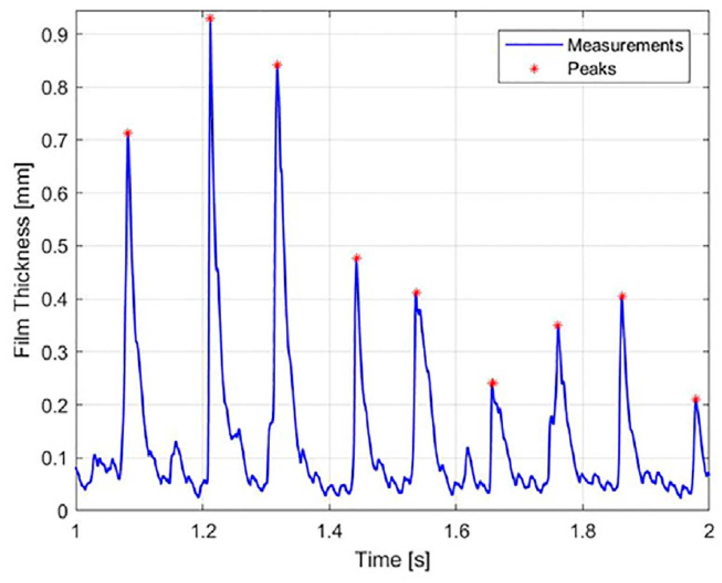
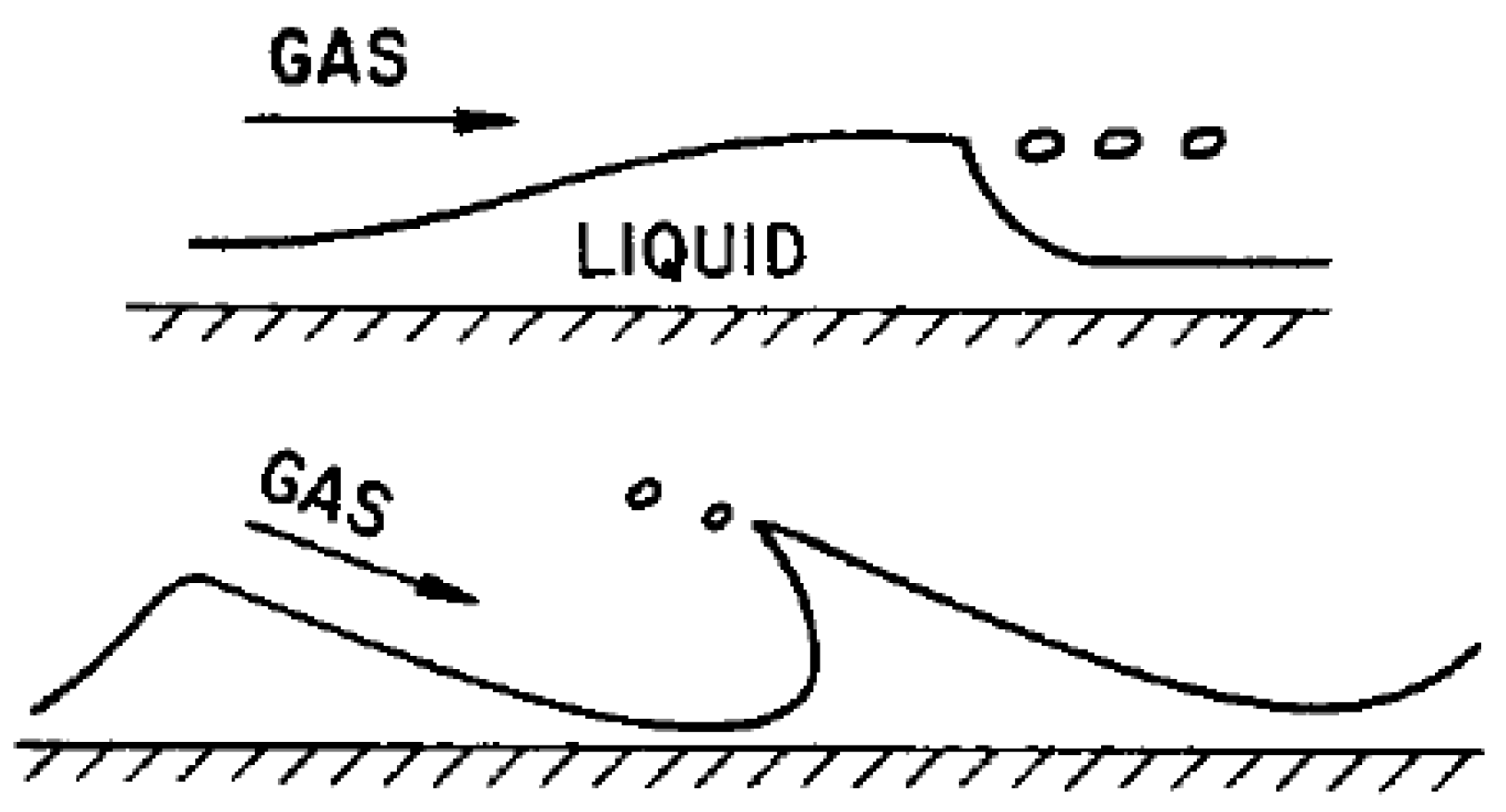
Such probes were intensively used to obtain temporal records of film thickness and study the wave structure. It was established that the appearance of entrained droplets (detected based on visual observations or sampling probe studies) requires the presence of large-amplitude liquid structures on the film surface. These structures are known as “disturbance waves”. Due to the limitations of the technique described above, the disturbance waves in such records have a smooth shape with a steep front slope and a single well-pronounced crest (Figure 1). Based on this shape, two hypotheses were proposed in [29]: shearing-off the disturbance wave crests and wave undercutting (Figure 2). Though these hypotheses did not receive any direct experimental confirmation, they remain the most popular in the literature; the former hypothesis is used as the basic assumption in majority of the aforementioned simplified physical models.
The non-optical techniques have wider capabilities than merely taking film thickness records in one point. It is possible to create multi-component probes, obtaining the records simultaneously in many points, obtaining the film thickness records resolved along one [30] or two [31,32] spatial coordinates. E.g., in [30] it was found that the waves on the base film are produced at the rear slope of the disturbance waves, and in [31] it was shown that the disturbance waves, even if they are closed around the pipe circumference, show strong amplitude variation in circumferential direction and also large temporal variation as they propagate downstream. Nonetheless, such approaches are limited by the wall film measurements and are hardly suitable for studying the droplets simultaneously with the waves. The measurements in the central part of the duct can be made with tomographic modifications of conductance/capacitance techniques, namely, wire-mesh sensor [33] and electric capacitance tomography [34], respectively. Such approaches allow one to reconstruct instantaneous distributions of the liquid phase in one cross-section of the duct. However, these measurements are not resolved in longitudinal coordinate; the results are also averaged over the distance between the sensor layers; the accuracy of the reconstruction is also quite limited by the large distance between neighboring wires or by the number and size of the capacitance plates.
3. Shadow Visualization: From Simplicity to Complexity
Optical techniques are convenient for observing a large spatial domain. Thus, it is easy to observe a complex object evolving in time and shifting in space; multiple objects of a different nature (e.g., waves and droplets) can be studied simultaneously. In the further analysis, we consider only the approaches employing domain-based measurements and ignore the techniques limited to pointwise applications such as laser focus displacement [35], total internal reflection [36], chromatic confocal imaging [37], etc. Moreover, in this section we only discuss the direct optical visualization approach, which normally consists in imaging the flow illuminated by white light.
Obviously, one camera can see one spatial plane. Three spatial coordinates would define three main working planes. We denote the axis parallel to the flow direction—longitudinal coordinate—as x. The transverse coordinate parallel to the wall over which the film flows is denoted as y. The transverse coordinate orthogonal to the wall and the film surface is denoted as z. In pipes, y-coordinate can be referred to as the circumferential or azimuthal coordinate and can be also replaced by the azimuthal angle in polar coordinates with the origin at the pipe axis. Respectively, the z-coordinate can be referred to as the radial coordinate, and x as the axial coordinate.
The simplest way to visualize flow in pipes is to obtain backlit images in x-y planes. The lamp is placed on one side of the pipe, and the camera “sees” this light passing through the flow. In the very first studies it was observed that the disturbance waves have a “milky” appearance due to strong agitation of their surface. This alone contradicts the “smooth” profiles of disturbance waves obtained by low-resolution conductance probes as mentioned above, and to the related hypotheses.
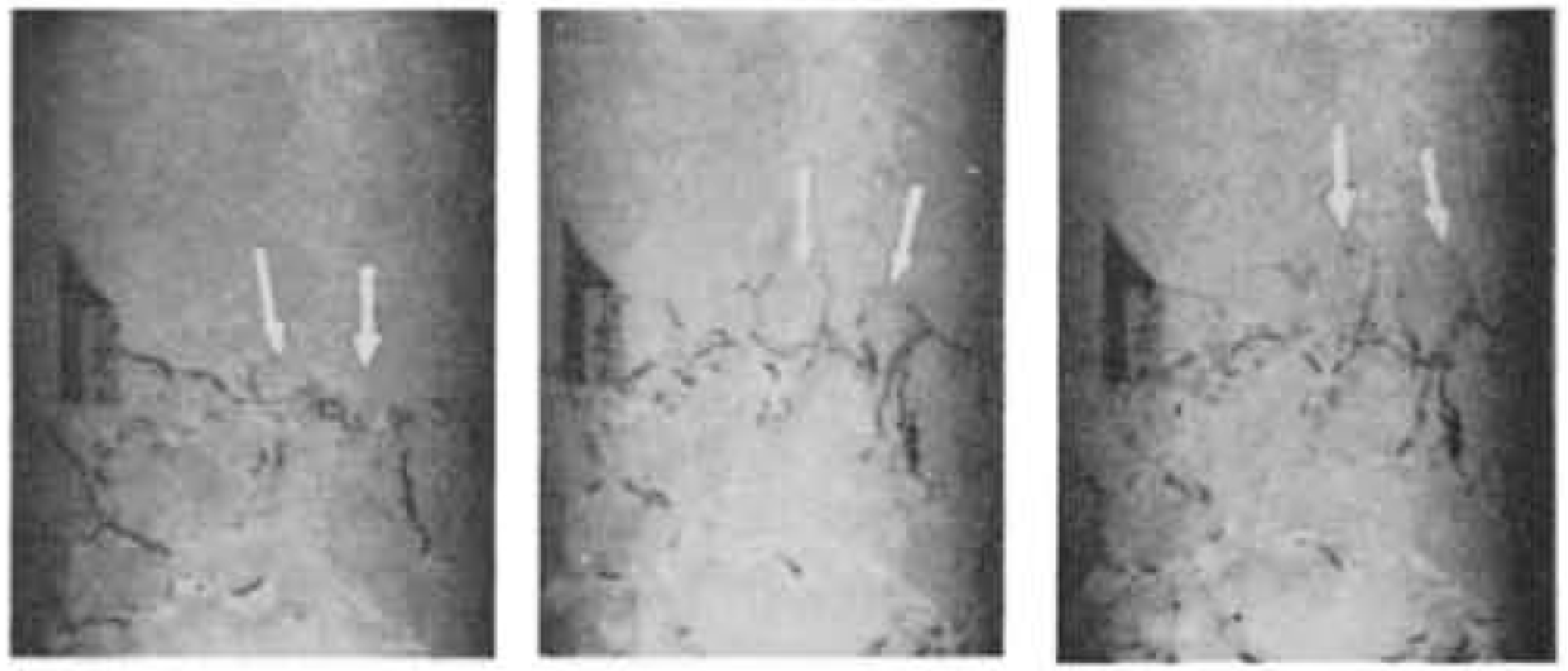
For annular flow inside pipes the whole pipe wall is covered by agitated liquid film. Therefore, it is quite difficult to organize a clear view of the objects in the gas core through this interface. On the other hand, it is generally agreed that the disturbance waves are qualitatively the same in ducts of different size, shape and orientation, despite the related quantitative difference in wave parameters. The first comprehensive study of the interrelation between the roughness of disturbance wave surface and liquid entrainment was made in [38] on a liquid film flowing along the bottom of a horizontal rectangular duct by viewing the film from the top (i.e., in the x-y plane). It was found that there exist smaller-scale horseshoe-shaped “ripples” on top of disturbance waves (Figure 3). Under the action of gas shear, these ripples got stretched like soap bubbles and broken into a number of droplets. This scenario is more complex than those proposed in [29]. Moreover, it is more plausible: shorter structures are easier to deform and break by the gas stream than the whole crest of a disturbance wave, which normally has a large longitudinal size of the order of 1 cm. Some more recent visualization studies in pipes (e.g., [18,39]) generally follow the pattern proposed in [38].
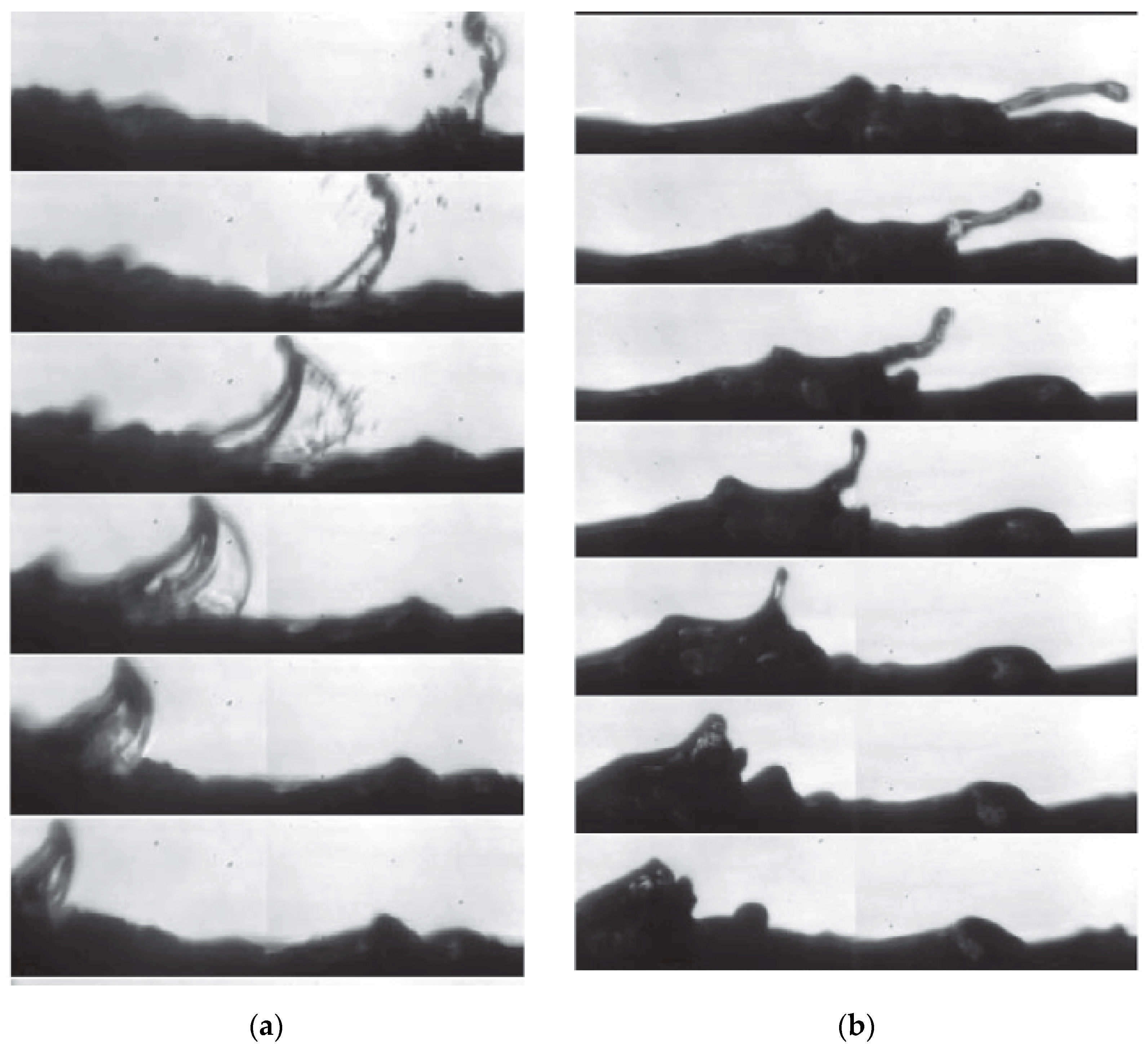
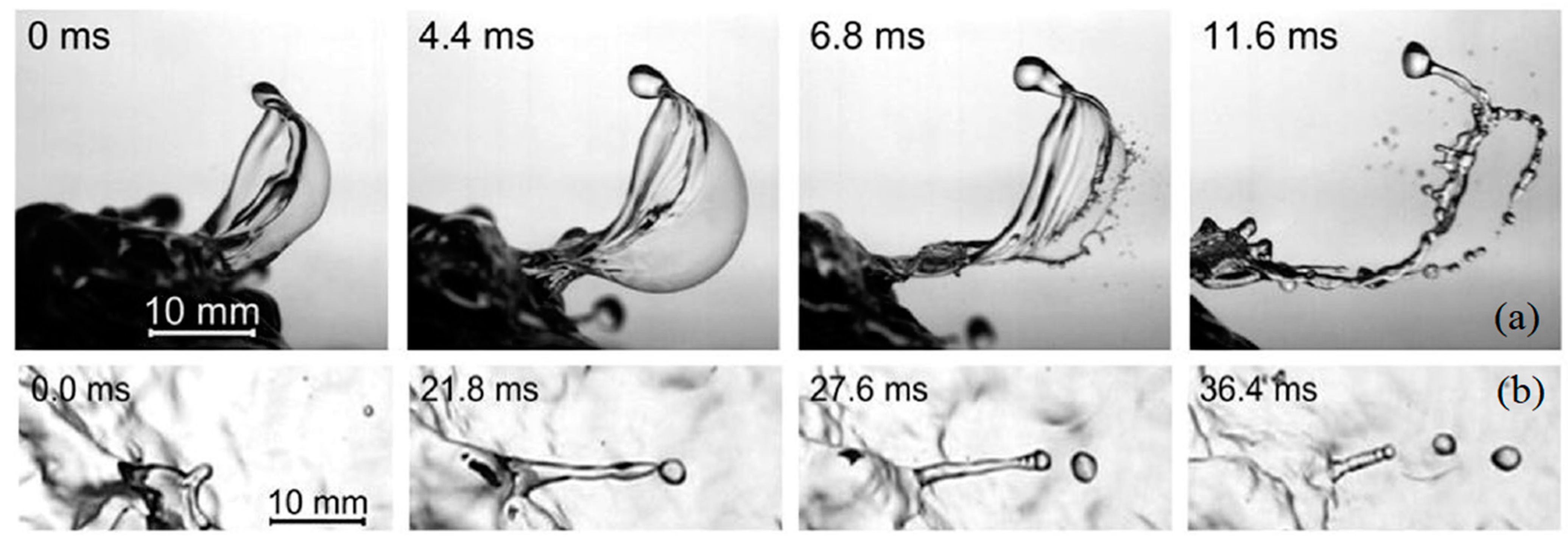
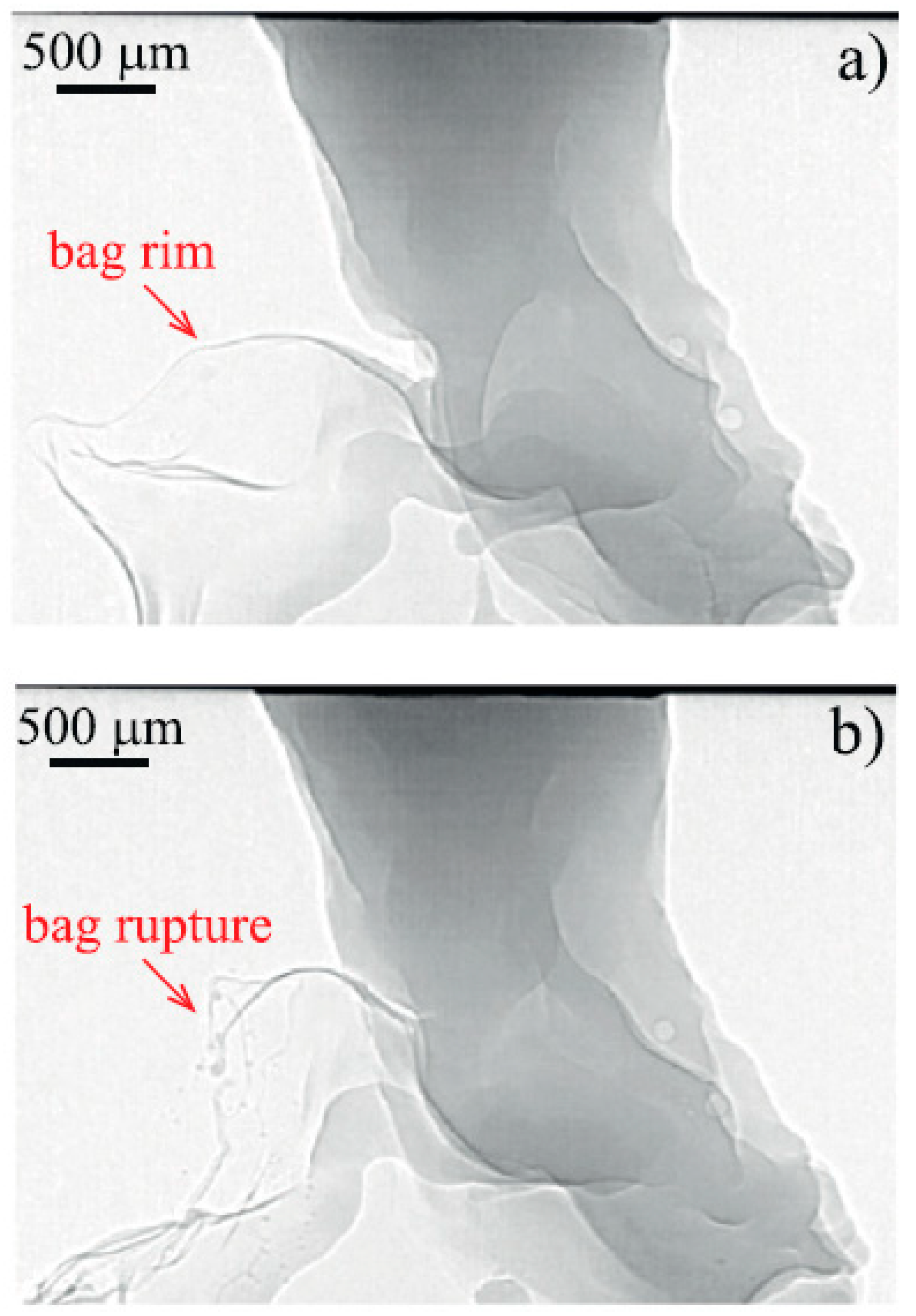
The same process was observed later in [40] in the y-z plane. This camera was oriented along the pipe axis through a specially organized viewing window. Although in this configuration it is impossible to distinguish between the disturbance waves and ripples on top of them, the deformed liquid structures being shattered into droplets can be clearly seen. Using an analogy with secondary atomization of droplets in a gas stream, the entrainment events were separated into two types: bag break-up and ligament break-up (Figure 4). The former (Figure 4a) is very likely the same as the process observed in [38]: part of a wave is blown into a liquid bag; at some point, this bag gets torn into many droplets. During the latter (Figure 4b), an isolated liquid jet (“ligament”) is formed from the film surface; this ligament is then broken into a small number of relatively large droplets. The break-up of a ligament is reminiscent of Rayleigh–Plateau instability. Later, similar observations were made in [41,42].
The direct visualization of the entrainment process in the x-z plane was made in [43]. In this work, there was clear optical access to the breaking wave and droplets, since the film was flowing on the outer surface of a cylinder (namely, part of a rectangular rod bundle mimicking nuclear installations). Again, bag and ligament break-up can be observed (Figure 5). It is also quite clear that only a small fraction of a disturbance wave—namely, a short ripple on its surface—directly participates in the entrainment process.
It is also educational to see the entrainment visualization presented in the works [44,45], where laboratory-modeled sea waves were studied in a large (20 m by 2 m by 2 m) tank sheared by strong wind. The visualization was carried out in both the x-z and x-y planes, and the same events of bag and ligament break-up were observed (Figure 6). In this case it is especially clear that the wind does not tear off the crests of the large-scale waves, which are orders of magnitude higher and longer than the disturbance waves in annular flow. On the opposite, the typical transverse size of the bags created on the surface of deep gas-sheared liquid layer, is of the order of 1 cm. The transverse and longitudinal size of the ripples broken into droplets in the annular flow is of the same order of magnitude [46].
For both the thin-film flow [43] and the deep-layer flow [45], it is reported that the liquid bag consists of a thin central film and a thicker rim around it. The central film is broken first into small droplets; afterwards, the rim is broken into larger droplets.
The entrainment events presented in Figure 3, Figure 4, Figure 5, Figure 6 are essentially three-dimensional. The only expected kind of symmetry is the bilateral symmetry of a liquid bag, which is also not necessarily true. Quantitative optical investigations require simultaneous imaging of the entrainment events in at least two planes.
Such investigation can provide the dynamic characteristics of the transitional liquid structure (i.e., bag or ligament), together with the characteristics of the entrained droplets. However, the important characteristics of liquid film, including the parameters of the disturbance wave and three-dimensional evolution of the ripples that serve as the basis for formation of the transitional liquid structures, cannot be extracted merely from shadow visualization. An additional technique applicable for film thickness measurements and compatible with optical visualization is required.
4. Planar Laser-Induced Fluorescence (PLIF) Technique: Deceptive Clarity
The planar LIF method is based on direct imaging of one section of a liquid film (doped with fluorescent dye) illuminated by a laser sheet. The sheet is usually oriented in the x-z plane, and the camera views the fluorescing liquid along y-axis. For annular flow, this method is mainly applied in circular pipes [47,48,49,50,51]. In some of these papers [49,51], the authors claim that entrainment events can be observed directly using PLIF technique. Sometimes, such images are interpreted based on seeming similarity to previously reported entrainment mechanisms [49], and sometimes, the interpretation involves the construction of new hypotheses [51].
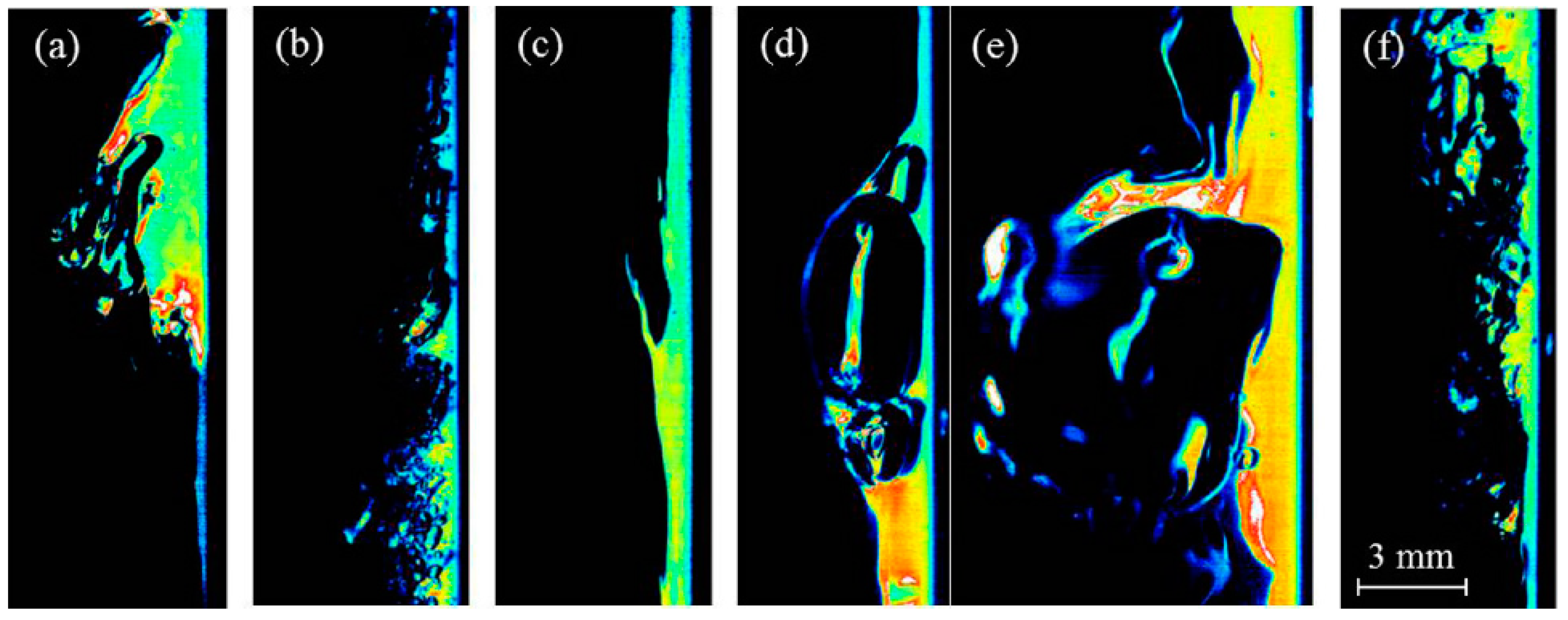
Figure 7 shows a number of such events presented in [49]. In this work, a downward air-water annular flow was studied in a 32.4 mm diameter pipe. The bright areas in the images are presumably occupied by liquid. The pipe wall is on the right-hand side of each sub-image, and the interface is on the left. The flow direction is from top to bottom. The events presented in Figure 7a,b were interpreted as shearing-off disturbance wave crests and disturbance wave undercutting, respectively, since they are reminiscent of the images shown in Figure 2. Figure 7c shows a structure reminiscent of a liquid ligament (see Figure 4b, Figure 5b and Figure 6b). Figure 7d-e and Figure 7f are interpreted, respectively, as bursting of a large bubble and droplet impingement, discussed in [29] and before.
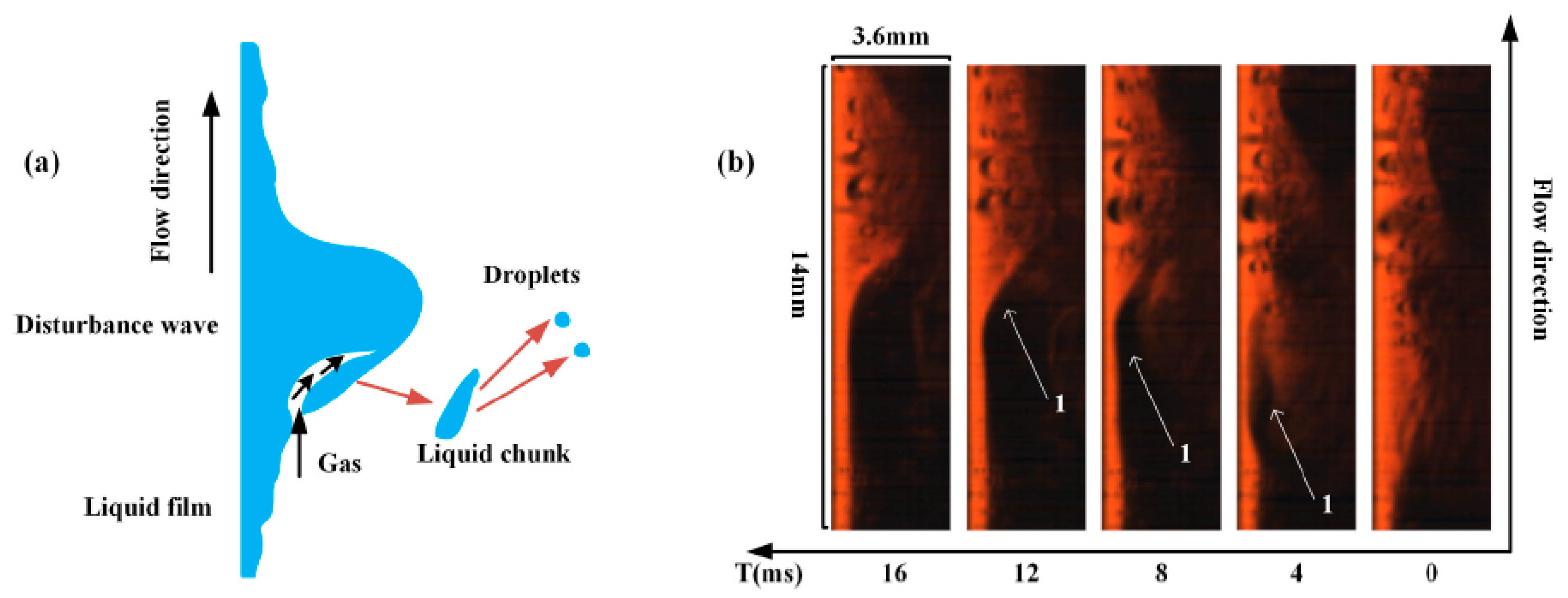
In [51], upward annular flow was studied in a 25 mm pipe. Figure 8b shows an example sequence of PLIF-images. In this image, the pipe wall is on the left, and the flow goes upwards. In total, five types of entrainment events were allegedly observed. These events are not directly related to previously proposed hypotheses; instead, new hypotheses are constructed. All the event types are alike; they are all related to the partial disappearance of a disturbance wave image. The difference between the types is related to which part of a wave disappears: the whole small-scale wave (type 1); the front part of a large wave (type 2); the rear part of a large wave (type 3, see Figure 8); the top part of a large wave (type 4); part of wave containing a bubble image (type 5).
The images presented above may seem to be a direct visualization of the entrainment process, but this interpretation is doubtful from both hydrodynamics and optics points of view. Let us first list the issues related to hydrodynamics. The events shown in Figure 7a,b exactly correspond to hypotheses based on speculation [29] and not observed with plain visualization. The ligament formation (Figure 7c) was observed indeed in visualization studies, but in all cases the ligaments are oriented along the flow (see Figure 5b, Figure 6b, and Figure 13b), whilst in Figure 7c it is oriented against the flow. All the entrainment “types” suggested in [51] assume that a very strong and narrow gas jet literally cuts through the liquid, “slicing” it in chunks. Such behavior does not look plausible, especially with a low gas speed of 6 m/s. Besides, the probability of all entrainment events in [51] is reported to decrease quickly with increasing gas speed, which also contradicts all measurements of entrainment intensity (see, e.g., [13,14]).
From an optics point of view, it is not likely that the process of entrainment can be directly observed in the PLIF-images without any distortion. Analysis of optical distortions related to PLIF-imaging in pipes was carried out in [52,53], though these papers mainly dealt with the error of film thickness measurements. At present, no analysis considering optical distortions for PLIF-visualization of the entrainment phenomena is presented in the literature. For that reason, such analysis will be carried out in the present review.
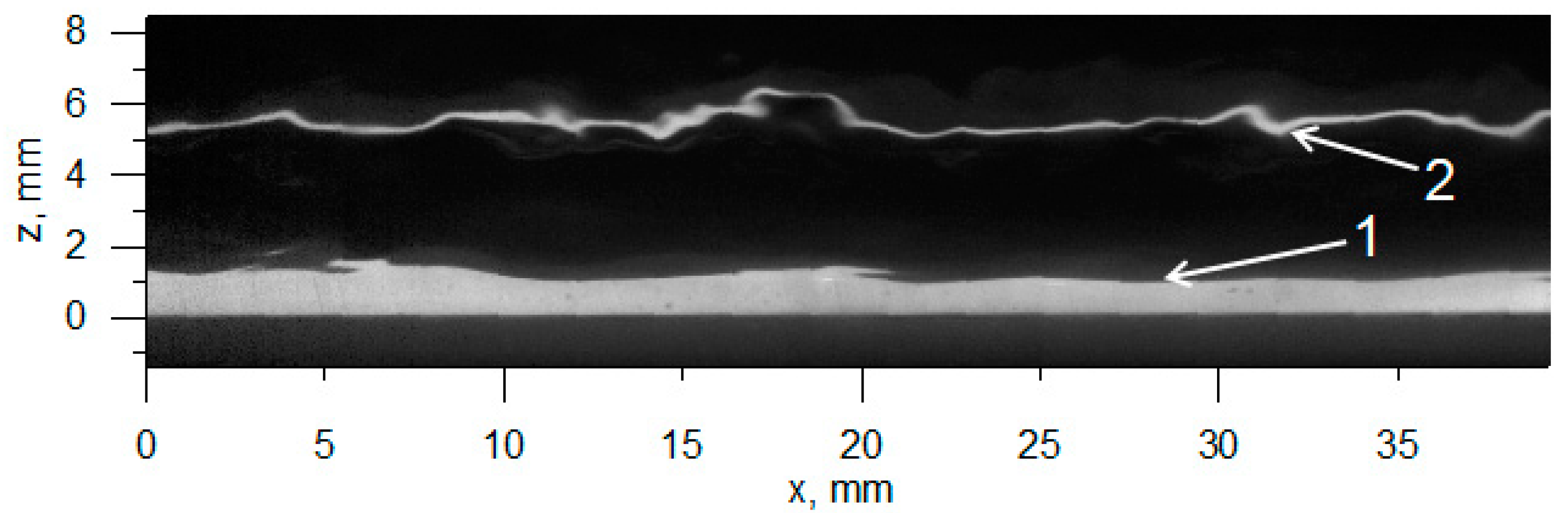
Let us start with a simple case of annular film with nearly uniform thickness. An example of a raw PLIF-image for such case (flow of liquid film falling under the action of gravity along the inner walls of a vertical pipe) is shown in Figure 9. A typical PLIF-image consists of a bright stripe near the pipe wall and a dark area above it. There also might appear a thin bright line above the film image far in the dark area (so-called “ghost image”). It should be noted that there appear to be some “barbs” on the film surface (at x = 6 mm and x = 20 mm), even in absence of gas flow and entrainment. A straightforward interpretation of PLIF-images is that the bright stripe shows the film profile and the dark area shows the gas above this film in the illuminated pipe section.
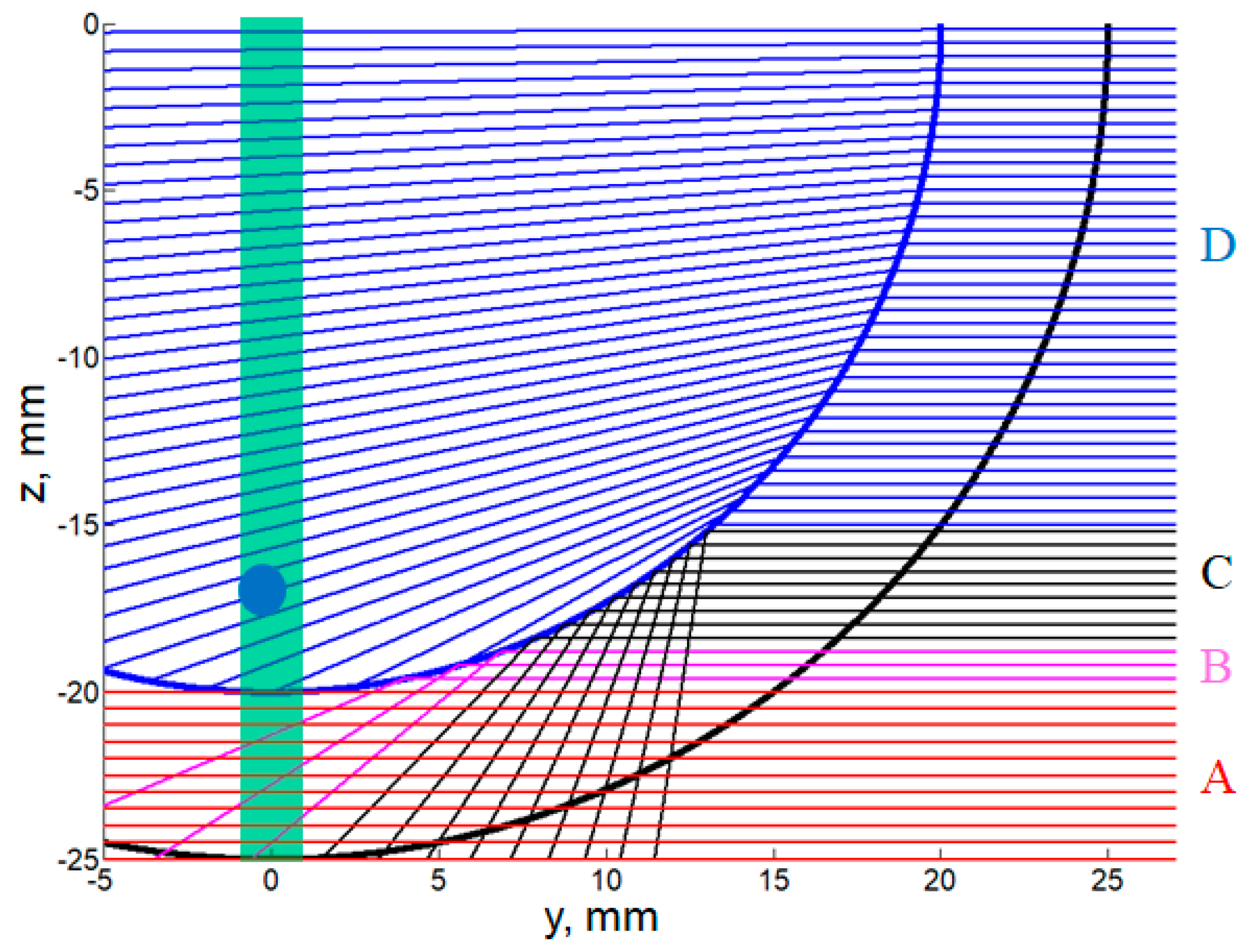
To understand how correct this interpretation is, let us consider the application of the PLIF method to a waveless liquid film with a uniform thickness of 5 mm in a 50 mm diameter pipe (the numbers are arbitrary and do not quantitatively change the conclusions). A portion of such a pipe section is sketched in Figure 10; the interface is shown by thick blue line, and the pipe inner wall by thick black line. One longitudinal section of the film is illuminated by a laser sheet (shown by the pale green rectangle). The camera is viewing the pipe from the right. For simplicity, we assume that the angle between the camera axis and the laser sheet plane is 90°, and the rays going to camera are parallel. In addition, we neglect the refraction on the pipe inner wall. This assumption implies the same refraction coefficient for the liquid and pipe wall (e.g., if the pipe is made of FEP, see [49]), and a flat vertical outer wall of a pipe on the right-hand side (i.e., if the pipe is placed into an optical box, see [49]). The ray tracing is very simple here, based merely on Snell’s law, Fresnel equations, equality of the angles of incidence and reflection, and the geometry of the film and pipe. Namely, the ray path is defined by the angle α between the vector connecting the origin to a particular point at the interface, and the z-axis. The angle of incidence is then defined as π/2—α if this angle exceeds the angle of total internal reflection or TIR-angle (48.6° for air-water system), the ray will not pass through the interface.
As illustrated by the rays drawn in Figure 10, the real picture is quite different from the straightforward one. The rays passing through the illuminated section of the liquid film (shown by red lines in Figure 10 between z = –20 mm and z = –25 mm) indeed collect the fluorescence emitted by the laser-illuminated liquid film and show the real profile of film thickness (zone A). The rays slightly above this section (shown by magenta lines, between z = −20 mm and z = −18.5 mm) are totally internally reflected from the interface. After reflection, these rays also pass through the illuminated section of the film, so they also deliver fluorescence to the camera image, creating a false film image (see also [53]). The false image width is about 30% of that of the real image for a film of constant thickness (zone B). The false image is also deformed (namely, non-uniformly compressed along z) and turned upside down. Thus, the border of the bright stripe in the PLIF image does not correspond to the real interface, even if the 30% increase is taken into account. The real interface is inside the bright stripe. The brightness of real and false images is approximately the same, so the position of the true interface cannot be detected based on brightness values. Although sometimes a thin brighter or darker line can be seen where the true interface is located, its presence is not guaranteed [52].
The rays passing above the false image (shown by black lines, between z = −18.5 mm and z = −15 mm) are also totally internally reflected at the interface but they do not pass through the illuminated section of the film, so the pixels collecting fluorescence along these rays remain dark (zone C). These rays do not enter into the gas phase, so the image collected by them has no relation to the gas section above the film. Thus, any object above the film surface in the illuminated section (like an entrained droplet drawn in Figure 10 or a deformed liquid structure) cannot be seen by the camera in areas B and C.
Such objects can be observed in zone D by the rays passing even higher (the blue lines in Figure 10, for z > −15 mm). These rays do penetrate into the gas phase, though the reflection coefficient may be still high closely to zone C. The transmitted rays are refracted and hit the interface at different points. Those rays which pass through the illuminated section of the film (at z ~−13–14 mm for the circular interface) would create the ghost image of the film (as the one shown in Figure 9). Additionally, the interpretation of such an image as a reflection of the fluorescence from the farther wall of the pipe, proposed in [52], is incorrect: it is just fluorescence seen by the rays refracted at the closer wall. If some objects like droplets are in the laser sheet above the film, they absorb the light and emit fluorescence, so they can be seen in zone D. However, these objects will be seen far from the film image, separated by the false image zone B and the blind zone C; their images will be distorted by the curved interface even in the case of a smooth film of constant thickness. Moreover, in the flow conditions where droplets or complex liquid structures may appear, the whole film surface would be agitated with short-length three-dimensional waves. In this case, even the ghost image disappears from the PLIF-images due to strong distortions. Each interface perturbation on the optical path would work as a lens massively distorting the images of droplets, especially if the “focus distance” of such a “lens” is small compared to the distance from a droplet to the “lens”. Even worse, the laser sheet itself may be refracted at the agitated interface.
Given the above, none of the interpretations provided for Figure 7 is correct. The bright spots near the apparent interface (Figure 7a,b,f) are not related to droplets which cannot be seen in such a system. If the elongated structures connected to the interface, interpreted as liquid ligaments (specified for Figure 7c, but also observable for Figure 7a,b,f), were real, they would have not been visible in PLIF-images, being also hidden from view by an inclined interface. Only the bubble shown in Figure 7d,e is possibly a real large bubble. Most likely, this bubble is located between the laser sheet and the camera, judging by the bright longitudinal line in its center. A more detailed description of how to distinguish the real y-position of a bubble relative to the laser sheet can be seen in Section 3.4 in [52]. It is still unclear whether that bubble has actually burst or its upper border (i.e., thin liquid film covering the bubble) has just disappeared from view.
- (1)
- How a bright isolated area may appear in PLIF-images?
- (2)
- How a part of a bright area connected to the film image may disappear?
The simple modeling shows that both questions have the same answer and that this answer is related to the presence of three-dimensional waves on the film surface between the laser sheet and the camera, mainly in zones B and C shown in Figure 10. If all the waves were perfectly two-dimensional, i.e., if the cross-section of the interface was always circular (with only the radius varying due to passage of waves), the PLIF-image would have consisted only of the true and false film images, with an approximately constant ratio of their sizes. However, for three-dimensional waves, the position of the interface will show oscillations along the azimuthal coordinate; the local azimuthal slope and, hence, the incidence angle, will also undergo strong variations.
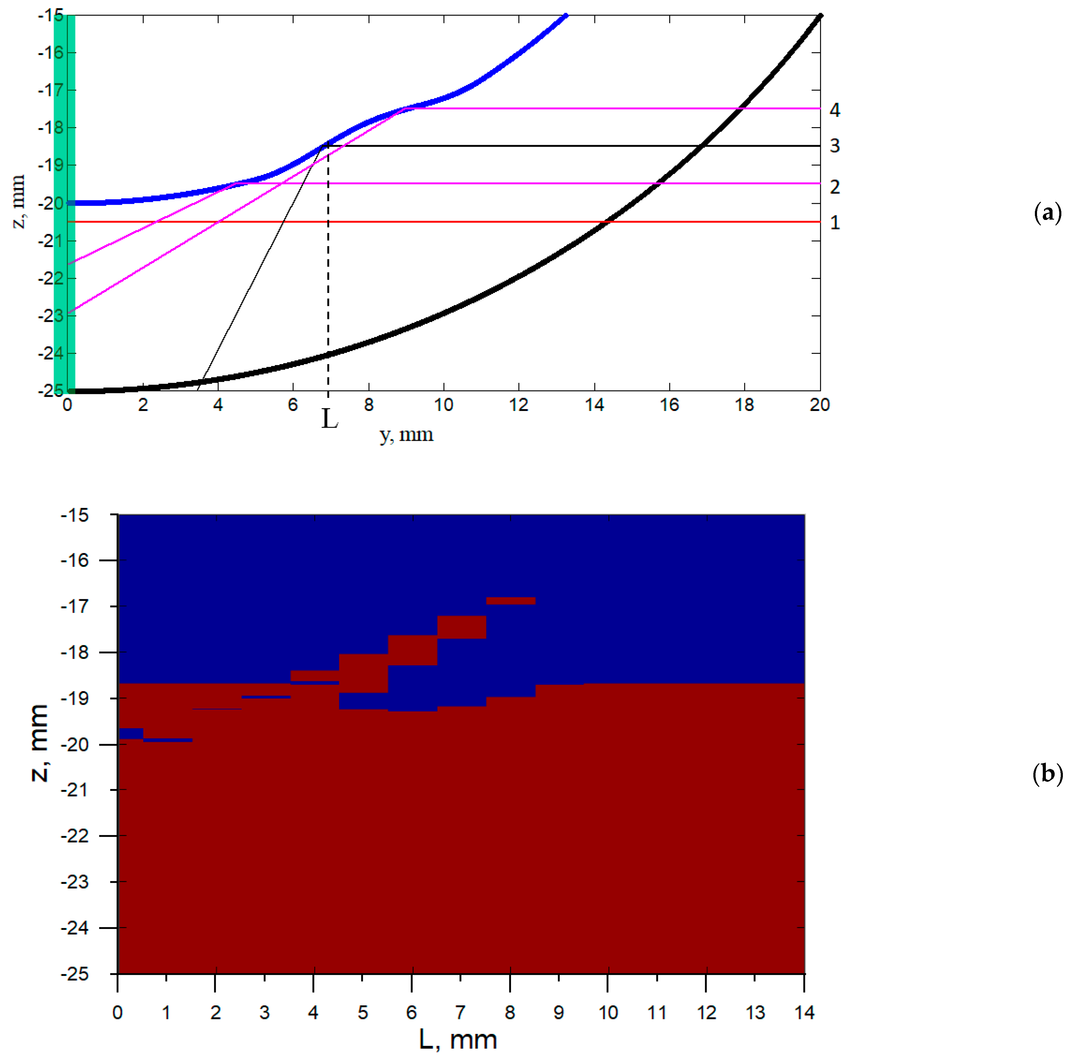
Figure 11a shows a fragment of uniform annular film with imposed small azimuthal perturbation of the film surface. The perturbation is selected in the form of one period of cosine function with amplitude of 0.5 mm (10% of film thickness) and azimuthal size of 6 mm. The position of this perturbation is characterized by the y-coordinate of its center, L. The perturbation does not affect the rays obtaining the true film image (see ray 1 passing at z = −20.5 mm), and the rays hitting the interface between the laser sheet and the perturbation (ray 2 at z = −19.5 mm). However, the rays reflected from the perturbed area may not reach the illuminated section of the film due local change of the interface slope (ray 3 at z = −18.5 mm). The rays reflected near the outer edge or outside the perturbation (ray 4 at z = −17.5 mm), may again hit the illuminated section and create a bright patch in the false film image.
In general, a ray may create a bright spot in the false film image region if the conditions below are satisfied:
- (1)
- The reflection coefficient of a ray hitting the interface is close or equal to unity. This means that the angle of incidence, taking into account the local change of interface slope due to the perturbation, is close to the TIR-angle or exceeds it.
- (2)
- The reflected ray crosses the laser-illuminated section of the film.
- (3)
- There is no interface on the reflected ray’s optical path between the reflection point and the illuminated section.
Technically, there could appear bright spots in more complicated cases. For example, the reflected ray hitting the interface (condition 3 is broken) may get totally reflected again into the illuminated section. Alternatively, the ray hitting a local steep slope may pass through the interface (condition 1 is broken) and be refracted to penetrate again into the illuminated film section. Such cases were neglected in the present analysis: if any of the conditions (1–3) is not satisfied, the corresponding camera pixel level is set to zero; if all the conditions are satisfied, it is set to unity.
Figure 11b shows how the raw PLIF brightness profile would look at different y-positions of the perturbation. If L = 0, the upper edge of the false film image does not change; however, its bottom part will be darkened by the right edge of the perturbation. It should be noted that in this case the true film thickness in the illuminated section is 10% higher, but it is not detected by PLIF. In the medium range of L (5–8 mm), part of the false image will be darkened, reducing the apparent film thickness. There will also appear an additional bright spot above the film image, creating an illusion of a droplet above the film surface or a liquid ligament/overturning wave if this bright area is still connected to the true/false film image at neighboring x. This spot may be also shifted far from the area of the false film image, strengthening the illusion of a droplet flying above the interface. If the perturbation is located outside the false film area (L ≥ 10 mm), it does not affect the false image.
Thus, the presence of even a small and smooth perturbation effectively “shatters” the “mirror” surface creating the false film image. Parts of this surface stop acquiring fluorescence due to altering the path of reflected light, which leads to temporal disappearance of the false film image and, in the case of severe perturbations, part of the true film image as well. This effect can make an illusion of disappearance of part of a wave, which can be further erroneously interpreted as liquid entrainment (as it was done in [51]). Furthermore, some “shards” of the “shattered mirror” may still collect fluorescence, creating isolated bright spots in PLIF image. These spots can be erroneously interpreted as liquid droplets or structures connected to the film (liquid ligaments, overturning waves) and attributed to entrainment events, as it was done in [49].
In real annular flow with entrainment, the film surface is strongly agitated by the gas shear, being covered with three-dimensional ripples on top of disturbance waves and on the base film. These waves may have a variety of amplitude and transverse size values, introducing more severe perturbations of the film surface compared to the one analyzed above. The disturbance waves themselves are not uniform in amplitude across the pipe circumference [31]. Their fronts (as well as those of ripples) may be curved or slanted in the x-y plane [46]; as a result, additional azimuthal slopes may appear in the y-z cross-section studied by PLIF.
To summarize, optical artifacts created by the “mirror” perturbations severely distort the PLIF images, making the PLIF technique inappropriate for studying the entrainment process. It should be also noted that the shadow visualization in the x-z plane inside circular pipes [54,55,56] is inapplicable to studying entrainment for similar reasons: neither droplets nor three-dimensional liquid structures in the investigated x-z plane will be seen due to the total internal reflection of light at the interface between the investigated pipe section and the camera. Besides, only the lowest film thickness value will be measurable in a given cross-section of the pipe.
5. Brightness-Based Laser-Induced Fluorescence (BBLIF) Technique: Enhancing the Visualization Studies
The BBLIF technique also employs the principle of laser-induced fluorescence, but the film thickness is recovered in a different manner compared to the PLIF method. Namely, both the camera and the laser are aimed at the same fragment of the x-y plane. Each pixel of the camera collects the fluorescence along a ray approximately normal to the wall and passing through the film. This value of fluorescence intensity is converted into local film thickness [46]. A matrix of film thickness, h(x,y), can be obtained at each time instant.
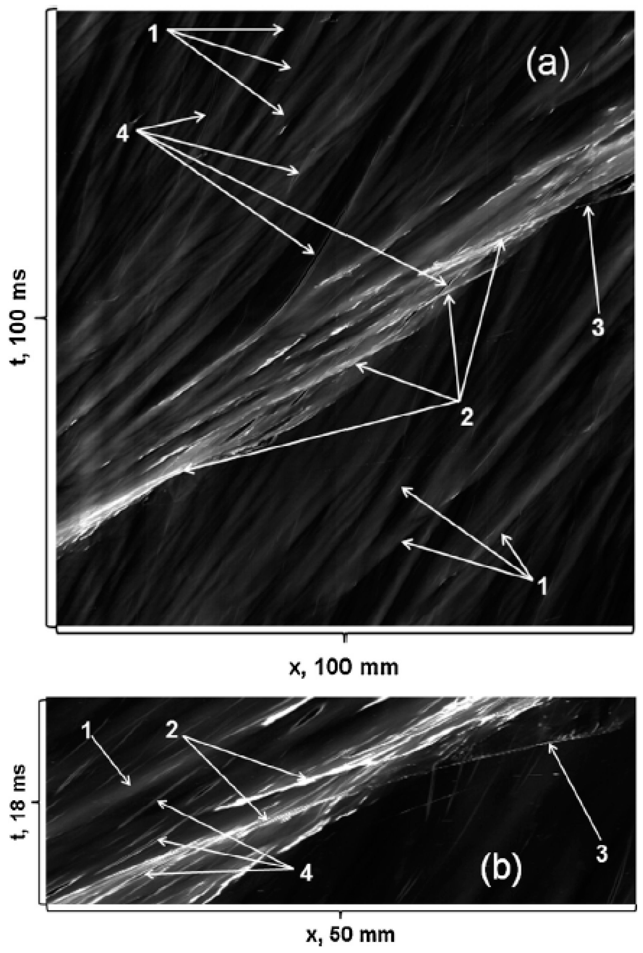
Application of this technique allows one to clarify the spatiotemporal dynamics and three-dimensional shape of the ripples on liquid film. Experiments in downward flow in a vertical pipe have shown [57] that all the ripples are generated at the rear slopes of disturbance waves. Depending on the relative x-coordinate of the point of inception, a ripple may either lag behind the “parent” disturbance wave and travel with low speed over the base film (“slow ripples”) or accelerate and travel with high speed over the disturbance wave (“fast ripples”). The same spatiotemporal evolution of ripples was observed in a horizontal rectangular duct [46]. At low liquid and high gas flow rates, where entrainment is not observed, fast ripples do not exist: only the “primary” waves generating slow “secondary” waves can be seen, and the crests of the primary waves remain smooth. This observation confirms that ripples on top of disturbance waves are necessary for liquid entrainment. The fast ripples often disappear from view when they reach the front of the disturbance wave or even before that. This happens due to shattering of the fast ripple into droplets as first described in [38]. Moreover, the entrained droplets are seen in the BBLIF data since they also contain the fluorophore; the spatiotemporal trajectory of such a droplet starts where the trajectory of the fast ripple disappears [58]. Figure 12 shows examples of the spatiotemporal evolution of disturbance waves, fast and slow ripples, and the entrained droplets.
Experiments [46] show that the fast ripples are three-dimensional and have horseshoe-shaped fronts in the x-y plane. These ripples are placed in a staggered order in several rows (the number of rows is mainly defined by the ratio of the longitudinal size of a disturbance wave to that of a fast ripple). The transitional liquid structures are distinguishable in BBLIF data since they also contain fluorophore. It was observed that the bag break-up occurs due to the deformation and breaking of the whole front of a fast ripple (Figure 13a). At the same time, ligament break-up occurs at the junctions of the side edges of neighboring fast ripples, where a longitudinally-oriented liquid hump is formed. The gas shear strips the liquid from this hump and forms a ligament oriented in the flow direction (Figure 13b). Indeed, the ligaments are most frequently observed between fast ripples.
Both the longitudinal and transverse size of fast ripples decreases as the gas speed is increased [46]. Thus, the amount of entrainment events of both types per unit surface area is expected to grow with gas speed. The relative contribution of the bag break-up mechanism into total liquid entrainment is expected to get smaller compared to that of the ligament break-up at high gas flow rates. The reason is that each broken ripple becomes narrower; hence, less liquid is torn from film surface via bag break-up. At the same time, the number of junctions where ligaments are formed increase with gas speed.
For a complete description of the entrainment events, the BBLIF can be combined with simultaneous visual observations in the x-z plane. An additional camera looking from the side can be employed and synchronized with the BBLIF camera. No additional light source is required for the second camera since it may also use the same laser illumination. Within this approach, all instantaneous coordinates of the entrained droplets may be obtained, together with the shape of the transitional structures and overturning waves. A detailed description of such a stereoscopic approach is given in [59]. Though that paper mainly deals with impact of previously entrained droplets on the film surface, the same data can be used to investigate the entrainment events. Figure 14 shows an example of an entrainment event seen by two cameras simultaneously.
The BBLIF technique has its own optical artifacts. At steep interface slopes, approaching and exceeding the TIR-angle, defined approximately as dh/dx ≥ 1 and/or dh/dy ≥ 1, the coefficient of the reflection of light from the interface is of order of unity, which is unaccounted in the film thickness calculation process. This reflection leads to the appearance of narrow but high-amplitude non-physical peaks of film thickness exactly on the steep slopes (see, e.g., [52]). This phenomenon does not affect the film thickness measurements on the base film, or rear slopes of disturbance waves, or even in the fast ripple area before the intensive deformation into a liquid bag or ligament begins, so it is possible to quantitatively investigate the initial stages of the entrainment process. After the deformation starts, all kinds of interface slopes, including those over 90⁰ with overturning, are possible.
The real height of the deformed fast ripples and more complex structures may be extracted from the images obtained by the second camera in a stereoscopic approach as described above. It must be noted that the optical distortions at steep slopes are inherent not only to BBLIF, but to the majority of intensity-based optical techniques, including light-absorption techniques [60,61], pigment luminance technique [62], reflection-based [63], and Schlieren-based methods [64,65,66].
6. X-ray Technique: Towards Distortion-Free Experiments
The optical distortions described above appear due to the strong difference in refractive indices of liquid and gas, which manifest themselves at steep local slopes of the interface. The only way to safely avoid such issues is to eliminate this difference. To the best of our knowledge, it cannot be solved by the selection of liquids and gas, since the difference remains large enough for any combination of gas and liquid. However, it can be eliminated by using non-optical radiation, namely, X-rays, as the main measurement tool. For X-rays, the refractive index in both liquid and gas is very close to unity. At the same time, the attenuation rate of the radiation intensity is different in gas and liquid media, so the spatial distribution of the two phases can be distinguished by comparing the intensity of rays passing through the media.
The pioneering X-ray visualization studies of annular flow [67,68] have shown the ability of this technique to overcome the optical obscuring of the objects in the gas core by agitated liquid film on pipe walls. In particular, complex liquid structures (“wisps”) were observed in the gas core at large liquid flow rates. Most likely, such structures appear due to the same bag and ligament break-up mechanisms. However, in this case bags and ligaments are not entirely scattered into droplets; instead, large amorphous chunks of liquid are detached from the film surface and carried by the gas stream.
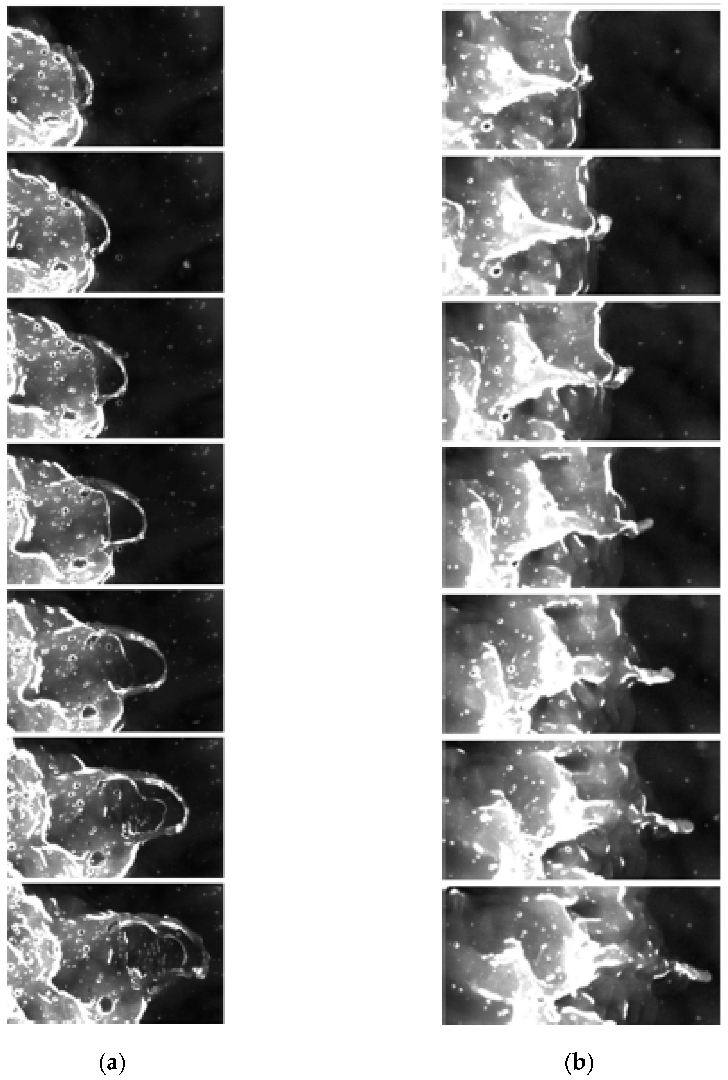
A recent review of applications of the X-ray tomography technique to various multiphase flows can be found in [69]. A number of researchers [70,71,72] used X-ray radiography to obtain cross-sectional void fraction distributions in stratified and annular gas-liquid flow in pipes. Usually, two source-detector systems oriented along the y and z axes were used simultaneously to reconstruct liquid phase distribution. In [73], the system rotated at low speed to obtain time-averaged circumferential and longitudinal film thickness profiles before and after an orifice in the pipe. However, studies of high-speed transient processes such as liquid entrainment are rare. In [74], a broad-band X-ray source was used for observation of the dynamics of an annular liquid sheet, detached liquid droplets, and entrapped air bubbles in an atomizer (Figure 15). In this work, outstanding spatial and temporal resolution was achieved. Nonetheless, the attenuation rate depends strongly on the wavelength, so the quantitative reconstruction of liquid phase distribution is impossible using a broadband X-ray source; a monochromatic X-ray source is required instead.
An alternative way to avoid strong distortions is to use near-infrared radiation (NIR); in this range, the liquid refractive index is also reduced, though it does not exactly reach unity. This technique is also based on light attenuation by liquid and can be used to reconstruct instantaneous liquid distribution in the flow (see, e.g., [75,76]).
Application of X-ray or NIR attenuation techniques to entrainment studies have the same requirements as those for visible-light techniques, namely: obtaining instantaneous images of the flow in at least two planes; at least the measurements in the x-y plane must allow one to quantitatively reconstruct the local instantaneous film thickness; temporal and spatial resolution of the method must be less than the smallest temporal and spatial scale of the phenomenon under study. The advantages of these approaches are the possibility to investigate entrainment for annular flow in pipes and less risk of distortions produced by refraction and reflection.
7. Discussion and Conclusions
The physical mechanism of liquid entrainment from disturbance waves in annular gas-liquid flow is a long-discussed matter. A number of hypotheses concerning this mechanism were proposed based on experimental observations. The hypotheses on shearing-off the disturbance wave crests and undercutting of disturbance waves are based on the concept of smooth disturbance waves, which, in turn, stems from film thickness records obtained by low-resolution measurement techniques. Direct visualization studies of the entrainment process carried out in three different planes and BBLIF studies of spatiotemporal evolution of film thickness show that the surface of disturbance waves is unstable and covered with ripples of much smaller length but comparable amplitude. These ripples are generated at the rear slopes of disturbance waves and travel with high speed towards the fronts of disturbance waves. The ripples are broken into droplets by two possible mechanisms known as bag break-up and ligament break-up. The bag break-up occurs when a three-dimensional ripple wave grows and its whole front is stretched and blown up by the gas stream. The ligament break-up occurs at the junctions of fast ripples where liquid is stripped by the gas shear and a forward-oriented jet is formed. Similar processes are found on the surface of a deep layer of liquid when sea storm conditions are modeled experimentally. The typical scale of the bags on deep water is quite close to that on thin films.
Comprehensive studies require reconstruction of instantaneous film thickness in the plane of the wall to analyze the wave processes leading to entrainment, as well as detecting the position and size of entrained droplets in the same plane. Simultaneously, side-view visualization is needed to investigate the parameters of bags, ligaments, and entrained droplets, to finally gain three-dimensional characterization of these objects. With visible-light techniques, proper side-view visualization is possible only when there is no liquid film between the studied object and the camera, e.g., when liquid film flows on a single flat plane or on a convex surface. In annular pipe flows, a curved and agitated film surface on the side walls creates strong optical distortions, especially affecting the PLIF-technique. Such a challenge may be overcome by X-ray or near-infrared attenuation techniques, though no studies of entrainment with an appropriate problem statement have been carried out yet in annular flow. A brief summary of the applicability of experimental methods to the investigation of fast ripples and transitional structures is given in Table 1.
Finally, it must be noted that qualitatively the mechanisms of liquid entrainment are more or less clear at present. On the other hand, the quantitative data on the entrainment process are scarce: properties of fast ripples [46] and liquid bags [45] were measured only separately, and in very different conditions. The future studies of the entrainment process should report a quantitative analysis of the whole process, starting from the formation of fast ripples, formation and break-up of bags and ligaments, and creation of droplets.
Funding
The main analysis was carried out in the Institute of Applied Physics under support of Russian Science Foundation (project 21-19-00755). Analysis of PLIF distortions was carried out under the State Contract of the Kutateladze Institute of Thermophysics (Registration number 121031100246-5).
Conflicts of Interest
The author declares no conflict of interest.
References
- Van Nimwegen, A.T.; Portela, L.M.; Henkes, R.A.W.M. Modelling of upwards gas-liquid annular and churn flow with surfactants in vertical pipes. Int. J. Multiph. Flow 2018, 105, 1–14. [Google Scholar] [CrossRef]
- Tuttle, S.G.; Fisher, B.T.; Kessler, D.A.; Pfützner, C.J.; Jacob, R.J.; Skiba, A.W. Petroleum wellhead burning: A review of the basic science for burn efficiency prediction. Fuel 2021, 303, 121279. [Google Scholar] [CrossRef]
- Le Corre, J.M. Phenomenological model of disturbance waves in annular two-phase flow. Int. J. Multiph. Flow 2022, 151, 104057. [Google Scholar] [CrossRef]
- Sandá, A.; Moya, S.L.; Valenzuela, L. Modelling and simulation tools for direct steam generation in parabolic-trough solar collectors: A review. Renew. Sust. Energy Rev. 2019, 113, 109226. [Google Scholar] [CrossRef]
- Sawant, P.; Ishii, M.; Mori, M. Droplet entrainment correlation in vertical upward co-current annular two-phase flow. Nucl. Eng. Des. 2008, 238, 1342–1352. [Google Scholar] [CrossRef]
- Azzopardi, B.J. Turbulence modification in annular gas/liquid flow. Int. J. Multiph. Flow 1999, 25, 945–955. [Google Scholar] [CrossRef]
- Karami, H.; Pereyra, E.; Torres, C.F.; Sarica, C. Droplet entrainment analysis of three-phase low liquid loading flow. Int. J. Multiph. Flow 2017, 89, 45–56. [Google Scholar] [CrossRef]
- Lopes de Bertodano, M.; Assad, A.; Beus, S.G. Experiments for entrainment rate of droplets in the annular regime. Int. J. Multiph. Flow 2001, 27, 685–699. [Google Scholar] [CrossRef]
- Pitton, E.; Ciandri, P.; Margarone, M.; Andreussi, P. An experimental study of stratified–dispersed flow in horizontal pipes. Int. J. Multiph. Flow 2014, 67, 92–103. [Google Scholar] [CrossRef]
- Azzopardi, B.J.; Zaidi, S.H. Determination of entrained fraction in vertical annular gas/liquid flow. J. Fluids Eng. 2000, 122, 146–150. [Google Scholar] [CrossRef]
- van’t Westende, J.M.C.; Kemp, H.K.; Belt, R.J.; Portela, L.M.; Mudde, R.F.; Oliemans, R.V.A. On the role of droplets in cocurrent annular and churn-annular pipe flow. Int. J. Multiph. Flow 2007, 33, 595–615. [Google Scholar] [CrossRef]
- van Eckeveld, A.C.; Gotfredsen, E.; Westerweel, J.; Poelma, C. Annular two-phase flow in vertical smooth and corrugated pipes. Int. J. Multiph. Flow 2018, 109, 150–163. [Google Scholar] [CrossRef] [Green Version]
- Cioncolini, A.; Thome, J.R. Entrained liquid fraction prediction in adiabatic and evaporating annular two-phase flow. Nucl. Eng. Des. 2012, 243, 200–213. [Google Scholar] [CrossRef]
- Aliyu, A.M.; Almabrok, A.A.; Baba, Y.D.; Archibong, A.E.; Lao, L.; Yeung, H.; Kim, K.C. Prediction of entrained droplet fraction in co-current annular gas–liquid flow in vertical pipes. Exp. Therm. Fluid Sci. 2017, 85, 287–304. [Google Scholar] [CrossRef] [Green Version]
- Han, H.; Gabriel, K. A numerical study of entrainment mechanism in axisymmetric annular gas-liquid flow. J. Fluids Eng. 2007, 129, 293–301. [Google Scholar] [CrossRef]
- Kumar, P.; Das, A.K.; Mitra, S.K. Physical understanding of gas-liquid annular flow and its transition to dispersed droplets. Phys. Fluids 2016, 28, 072101. [Google Scholar] [CrossRef]
- Sato, Y.; Niceno, B. Large eddy simulation of upward co-current annular boiling flow using an interface tracking method. Nucl. Eng. Des. 2017, 321, 69–81. [Google Scholar] [CrossRef]
- Zhou, R.; Xia, T.; Wei, A.; Zhang, X. Investigation on liquid nitrogen and vaporous nitrogen countercurrent flow considering droplet entrainment. Cryogenics 2020, 109, 103125. [Google Scholar] [CrossRef]
- Holowach, M.J.; Hochreiter, L.E.; Cheung, F.B. A model for droplet entrainment in heated annular flow. Int. J. Heat Fluid Flow 2002, 23, 807–822. [Google Scholar] [CrossRef]
- Ryu, S.H.; Park, G.C. A droplet entrainment model based on the force balance of an interfacial wave in two-phase annular flow. Nucl. Eng. Des. 2011, 241, 3890–3897. [Google Scholar] [CrossRef]
- Liu, L.; Bai, B. Generalization of droplet entrainment rate correlation for annular flow considering disturbance wave properties. Chem. Eng. Sci. 2017, 164, 279–291. [Google Scholar] [CrossRef]
- Cherdantsev, A.V. Overview of physical models of liquid entrainment in annular gas-liquid flow. AIP Conf. Proc. 2018, 1939, 020006. [Google Scholar] [CrossRef]
- Chu, K.J.; Dukler, A.E. Statistical characteristics of thin, wavy films: Part II. Studies of the substrate and its wave structure. AIChE J. 1974, 20, 695–706. [Google Scholar] [CrossRef]
- Zhao, Y.; Markides, C.N.; Matar, O.K.; Hewitt, G.F. Disturbance wave development in two-phase gas–liquid upwards vertical annular flow. Int. J. Multiph. Flow 2013, 55, 111–129. [Google Scholar] [CrossRef] [Green Version]
- Rivera, Y.; Muñoz-Cobo, J.L.; Cuadros, J.L.; Berna, C.; Escrivá, A. Experimental study of the effects produced by the changes of the liquid and gas superficial velocities and the surface tension on the interfacial waves and the film thickness in annular concurrent upward vertical flows. Exp. Therm. Fluid Sci. 2021, 120, 110224. [Google Scholar] [CrossRef]
- Miya, M.; Woodmansee, D.E.; Hanratty, T.J. A model for roll waves in gas-liquid flow. Chem. Eng. Sci. 1971, 26, 1915–1931. [Google Scholar] [CrossRef]
- Han, H.; Zhu, Z.; Gabriel, K. A study on the effect of gas flow rate on the wave characteristics in two-phase gas–liquid annular flow. Nucl. Eng. Des. 2006, 236, 2580–2588. [Google Scholar] [CrossRef]
- Wang, G.; Dang, Z.; Ishii, M. Wave structure and velocity in vertical upward annular two-phase flow. Exp. Therm. Fluid Sci. 2021, 120, 110205. [Google Scholar] [CrossRef]
- Ishii, M.; Grolmes, M.A. Inception criteria for droplet entrainment in two-phase concurrent film flow. AIChE J. 1975, 21, 308–318. [Google Scholar] [CrossRef]
- Sekoguchi, K.; Takeishi, M.; Ishimatsu, T. Interfacial structure in vertical upward annular flow. Phys. Chem. Hydrodyn. 1985, 6, 239–255. [Google Scholar]
- Belt, R.J.; Van’t Westende, J.M.C.; Prasser, H.M.; Portela, L.M. Time and spatially resolved measurements of interfacial waves in vertical annular flow. Int. J. Multiph. Flow 2010, 36, 570–587. [Google Scholar] [CrossRef]
- Fershtman, A.; Barnea, D.; Shemer, L. Wave identification in upward annular flow-a focus on ripple characterization. Int. J. Multiph. Flow 2021, 137, 103560. [Google Scholar] [CrossRef]
- Vieira, R.E.; Parsi, M.; Torres, C.F.; McLaury, B.S.; Shirazi, S.A.; Schleicher, E.; Hampel, U. Experimental characterization of vertical gas–liquid pipe flow for annular and liquid loading conditions using dual wire-mesh sensor. Exp. Therm. Fluid Sci. 2015, 64, 81–93. [Google Scholar] [CrossRef]
- Abdulkadir, M.; Hernandez-Perez, V.; Kwatia, C.A.; Azzopardi, B.J. Interrogating flow development and phase distribution in vertical and horizontal pipes using advanced instrumentation. Chem. Eng. Sci. 2018, 186, 152–167. [Google Scholar] [CrossRef]
- Hazuku, T.; Takamasa, T.; Matsumoto, Y. Experimental study on axial development of liquid film in vertical upward annular two-phase flow. Int. J. Multiph. Flow 2008, 34, 111–127. [Google Scholar] [CrossRef]
- Hurlburt, E.T.; Newell, T.A. Optical measurement of liquid film thickness and wave velocity in liquid film flows. Exp. Fluids 1996, 21, 357–362. [Google Scholar] [CrossRef] [Green Version]
- Zhou, D.W.; Gambaryan-Roisman, T.; Stephan, P. Measurement of water falling film thickness to flat plate using confocal chromatic sensoring technique. Exp. Therm. Fluid Sci. 2009, 33, 273–283. [Google Scholar] [CrossRef]
- Woodmansee, D.E.; Hanratty, T.J. Mechanism for the removal of droplets from a liquid surface by a parallel air flow. Chem. Eng. Sci. 1969, 24, 299–307. [Google Scholar] [CrossRef]
- Zhang, Z.; Wang, Z.; Liu, H.; Gao, Y.; Li, H.; Sun, B. Experimental study on bubble and droplet entrainment in vertical churn and annular flows and their relationship. Chem. Eng. Sci. 2019, 206, 387–400. [Google Scholar] [CrossRef]
- Azzopardi, B.J. Mechanisms of Entrainment in Annular Two Phase Flow; AERE-R 11068; UKAEA Atomic Energy Research Establishment: Harwell, UK, 1983. [Google Scholar]
- Badie, S.; Lawrence, C.J.; Hewitt, G.F. Axial viewing studies of horizontal gas–liquid flows with low liquid loading. Int. J. Multiph. Flow 2001, 27, 1259–1269. [Google Scholar] [CrossRef]
- Lecoeur, N. Interfacial Behaviour in Stratified and Stratifying Annular Flows. Ph.D. Thesis, Imperial College, London, UK, 2013. [Google Scholar] [CrossRef]
- Pham, S.H.; Kawara, Z.; Yokomine, T.; Kunugi, T. Detailed observations of wavy interface behaviors of annular two-phase flow on rod bundle geometry. Int. J. Multiph. Flow 2014, 59, 135–144. [Google Scholar] [CrossRef]
- Troitskaya, Y.; Kandaurov, A.; Ermakova, O.; Kozlov, D.; Sergeev, D.; Zilitinkevich, S. Bag-breakup fragmentation as the dominant mechanism of sea-spray production in high winds. Sci. Rep. 2017, 7, 1614. [Google Scholar] [CrossRef] [PubMed] [Green Version]
- Troitskaya, Y.; Kandaurov, A.; Ermakova, O.; Kozlov, D.; Sergeev, D.; Zilitinkevich, S. The “bag breakup” spume droplet generation mechanism at high winds. Part I: Spray generation function. J. Phys. Oceanogr. 2018, 48, 2167–2188. [Google Scholar] [CrossRef]
- Cherdantsev, A.V.; Hann, D.B.; Azzopardi, B.J. Study of gas-sheared liquid film in horizontal rectangular duct using high-speed LIF technique: Three-dimensional wavy structure and its relation to liquid entrainment. Int. J. Multiph. Flow 2014, 67, 52–64. [Google Scholar] [CrossRef]
- Schubring, D.; Ashwood, A.C.; Shedd, T.A.; Hurlburt, E.T. Planar laser-induced fluorescence (PLIF) measurements of liquid film thickness in annular flow. Part I: Methods and data. Int. J. Multiph. Flow 2010, 36, 815–824. [Google Scholar] [CrossRef]
- Farias, P.S.C.; Martins, F.J.W.A.; Sampaio, L.E.B.; Serfaty, R.; Azevedo, L.F.A. Liquid film characterization in horizontal, annular, two-phase, gas–liquid flow using time-resolved laser-induced fluorescence. Exp. Fluids 2012, 52, 633–645. [Google Scholar] [CrossRef]
- Zadrazil, I.; Matar, O.K.; Markides, C.N. An experimental characterization of downwards gas–liquid annular flow by laser-induced fluorescence: Flow regimes and film statistics. Int. J. Multiph. Flow 2014, 60, 87–102. [Google Scholar] [CrossRef]
- Xue, T.; Li, Z.; Li, C.; Wu, B. Measurement of thickness of annular liquid films based on distortion correction of laser-induced fluorescence imaging. Rev. Sci. Instrum. 2019, 90, 033103. [Google Scholar] [CrossRef]
- Liu, J.; Xue, T. Experimental investigation of liquid entrainment in vertical upward annular flow based on fluorescence imaging. Prog. Nucl. Energy 2022, 152, 104383. [Google Scholar] [CrossRef]
- Cherdantsev, A.V.; An, J.S.; Charogiannis, A.; Markides, C.N. Simultaneous application of two laser-induced fluorescence approaches for film thickness measurements in annular gas-liquid flows. Int. J. Multiph. Flow 2019, 119, 237–258. [Google Scholar] [CrossRef]
- Häber, T.; Gebretsadik, M.; Bockhorn, H.; Zarzalis, N. The effect of total reflection in PLIF imaging of annular thin films. Int. J. Multiph. Flow 2015, 76, 64–72. [Google Scholar] [CrossRef]
- Pan, L.M.; He, H.; Ju, P.; Hibiki, T.; Ishii, M. Experimental study and modeling of disturbance wave height of vertical annular flow. Int. J. Heat Mass Transf. 2015, 89, 165–175. [Google Scholar] [CrossRef]
- Isaenkov, S.V.; Cherdantsev, A.V.; Vozhakov, I.S.; Cherdantsev, M.V.; Arkhipov, D.G.; Markovich, D.M. Study of primary instability of thick liquid films under strong gas shear. Int. J. Multiph. Flow 2019, 111, 62–81. [Google Scholar] [CrossRef]
- Lin, R.; Wang, K.; Liu, L.; Zhang, Y.; Dong, S. Study on the characteristics of interfacial waves in annular flow by image analysis. Chem. Eng. Sci. 2020, 212, 115336. [Google Scholar] [CrossRef]
- Alekseenko, S.; Antipin, V.; Cherdantsev, A.; Kharlamov, S.; Markovich, D. Two-wave structure of liquid film and wave interrelation in annular gas-liquid flow with and without entrainment. Phys. Fluids 2009, 21, 061701. [Google Scholar] [CrossRef]
- Alekseenko, S.V.; Cherdantsev, A.V.; Markovich, D.M.; Rabusov, A.V. Investigation of droplets entrainment and deposition in annular flow using LIF technique. At. Sprays 2014, 24, 193–222. [Google Scholar] [CrossRef]
- Cherdantsev, A.V.; Sinha, A.; Hann, D.B. Studying the impacts of droplets depositing from the gas core onto a gas-sheared liquid film with stereoscopic BBLIF technique. Int. J. Multiph. Flow 2022, 150, 104033. [Google Scholar] [CrossRef]
- Mendez, M.A.; Scheid, B.; Buchlin, J.M. Low Kapitza falling liquid films. Chem. Eng. Sci. 2017, 170, 122–138. [Google Scholar] [CrossRef]
- Yang, H.; Guo, Y.; Li, C.; Tao, J.; Zhang, Y.; Wu, W.; Su, M. Development of a two-line DLAS sensor for liquid film measurement. Spectrochim. Acta A Mol. Biomol. Spectrosc. 2020, 224, 117420. [Google Scholar] [CrossRef]
- Ohba, K.; Nagae, K. Characteristics and behavior of the interfacial wave on the liquid film in a vertically upward air-water two-phase annular flow. Nucl. Eng. Des. 1993, 141, 17–25. [Google Scholar] [CrossRef]
- Åkesjö, A.; Gourdon, M.; Vamling, L.; Innings, F.; Sasic, S. Hydrodynamics of vertical falling films in a large-scale pilot unit–a combined experimental and numerical study. Int. J. Multiph. Flow 2017, 95, 188–198. [Google Scholar] [CrossRef]
- Vinnichenko, N.A.; Pushtaev, A.V.; Plaksina, Y.Y.; Uvarov, A.V. Measurements of liquid surface relief with moon-glade background oriented Schlieren technique. Exp. Therm. Fluid Sci. 2020, 114, 110051. [Google Scholar] [CrossRef]
- Kofman, N.; Mergui, S.; Ruyer-Quil, C. Characteristics of solitary waves on a falling liquid film sheared by a turbulent counter-current gas flow. Int. J. Multiph. Flow 2017, 95, 22–34. [Google Scholar] [CrossRef]
- Cherdantsev, A.V.; Gavrilov, N.V.; Ermanyuk, E.V. Study of initial stage of entry of a solid sphere into shallow liquid with Synthetic Schlieren technique. Exp. Therm. Fluid Sci. 2021, 125, 110375. [Google Scholar] [CrossRef]
- Bennett, B.A.W.; Hewitt, G.F.; Kearsey, H.A.; Keeys, R.K.F.; Lacey, P.M.C. Paper 5: Flow visualization studies of boiling at high pressure. In Proceedings of the Institution of Mechanical Engineers, Conference Proceedings; SAGE: London, UK, 1965; Volume 180, pp. 260–283. [Google Scholar]
- Hewitt, G.F.; Roberts, D.N. Studies of Two-Phase Flow Patterns by Simultaneous X-ray and Flash Photography; AERE-M 2159; Atomic Energy Research Establishment: Harwell, UK, 1969. [Google Scholar]
- Aliseda, A.; Heindel, T.J. X-ray flow visualization in multiphase flows. Ann. Rev. Fluid Mech. 2021, 53, 543–567. [Google Scholar] [CrossRef]
- Hu, B.; Langsholt, M.; Liu, L.; Andersson, P.; Lawrence, C. Flow structure and phase distribution in stratified and slug flows measured by X-ray tomography. Int. J. Multiph. Flow 2014, 67, 162–179. [Google Scholar] [CrossRef]
- Skjæraasen, O.; Kesana, N.R. X-ray measurements of thin liquid films in gas–liquid pipe flow. Int. J. Multiph. Flow 2020, 131, 103391. [Google Scholar] [CrossRef]
- Bieberle, A.; Shabestary, A.M.; Geissler, T.; Boden, S.; Beyer, M.; Hampel, U. Flow morphology and heat transfer analysis during high-pressure steam condensation in an inclined tube part I: Experimental investigations. Nucl. Eng. Des. 2020, 361, 110553. [Google Scholar] [CrossRef]
- Porombka, P.; Boden, S.; Lucas, D.; Hampel, U. Horizontal annular flow through orifice studied by X-ray microtomography. Exp. Fluids 2021, 62, 5. [Google Scholar] [CrossRef]
- Machicoane, N.; Bothell, J.K.; Li, D.; Morgan, T.B.; Heindel, T.J.; Kastengren, A.L.; Aliseda, A. Synchrotron radiography characterization of the liquid core dynamics in a canonical two-fluid coaxial atomizer. Int. J. Multiph. Flow 2019, 115, 1–8. [Google Scholar] [CrossRef]
- Dupont, J.; Mignot, G.; Prasser, H.-M. Two-dimensional mapping of falling water film thickness with near-infrared attenuation. Exp. Fluids 2015, 56, 90. [Google Scholar] [CrossRef]
- Wang, C.; Zhao, N.; Fang, L.; Zhang, T.; Feng, Y. Void fraction measurement using NIR technology for horizontal wet-gas annular flow. Exp. Therm. Fluid Sci. 2016, 76, 98–108. [Google Scholar] [CrossRef]
Figure 1.
A temporal record of film thickness obtained by a flush-mounted conductance probe [25].
Figure 1.
A temporal record of film thickness obtained by a flush-mounted conductance probe [25].

Figure 2.
Entrainment hypotheses on shearing-off the disturbance wave crest (top) and disturbance wave undercutting (bottom) [29].
Figure 2.
Entrainment hypotheses on shearing-off the disturbance wave crest (top) and disturbance wave undercutting (bottom) [29].

Figure 3.
Visualization of entrainment due to break-up of ripples on top of a disturbance wave in a horizontal rectangular duct in the x-y plane [38].
Figure 3.
Visualization of entrainment due to break-up of ripples on top of a disturbance wave in a horizontal rectangular duct in the x-y plane [38].

Figure 4.
Visualization of entrainment due bag break-up (a) and ligament break-up (b) in a horizontal pipe in the y-z plane [42].
Figure 4.
Visualization of entrainment due bag break-up (a) and ligament break-up (b) in a horizontal pipe in the y-z plane [42].

Figure 5.
Visualization of entrainment due to bag break-up (a) and ligament break-up (b) on the outer surface of a vertical cylinder in the x-z plane [43].
Figure 5.
Visualization of entrainment due to bag break-up (a) and ligament break-up (b) on the outer surface of a vertical cylinder in the x-z plane [43].

Figure 6.
Visualization of entrainment: (a) due to bag break-up in the x-z plane; (b) ligament break-up in the x-y plane on surface of a 2 m deep gas-sheared liquid layer [44].
Figure 6.
Visualization of entrainment: (a) due to bag break-up in the x-z plane; (b) ligament break-up in the x-y plane on surface of a 2 m deep gas-sheared liquid layer [44].

Figure 7.
PLIF-images of downward annular flow [49]. The presented events are interpreted as: shearing-off disturbance wave crests (a); disturbance wave undercutting (b); liquid ligament (c); bubble burst (d,e); droplet impingement (f).
Figure 7.
PLIF-images of downward annular flow [49]. The presented events are interpreted as: shearing-off disturbance wave crests (a); disturbance wave undercutting (b); liquid ligament (c); bubble burst (d,e); droplet impingement (f).

Figure 8.
PLIF images in upward annular flow [51]. The event is interpreted as entrainment due to “shearing of the ending of the disturbance wave”. (a) A sketch illustrating the proposed interpretation; (b) A sequence of raw PLIF-images with part of a wave image disappearing.
Figure 8.
PLIF images in upward annular flow [51]. The event is interpreted as entrainment due to “shearing of the ending of the disturbance wave”. (a) A sketch illustrating the proposed interpretation; (b) A sequence of raw PLIF-images with part of a wave image disappearing.

Figure 9.
Raw PLIF-image of a falling film flow in a vertical 32.4 mm pipe; taken from the experimental data set [52]. (1) PLIF-image of liquid film (both true and false image, see below); (2) “Ghost” image of the film seen through the pipe wall.
Figure 9.
Raw PLIF-image of a falling film flow in a vertical 32.4 mm pipe; taken from the experimental data set [52]. (1) PLIF-image of liquid film (both true and false image, see below); (2) “Ghost” image of the film seen through the pipe wall.

Figure 10.
Rays leading to the camera in the PLIF method. The calculations are made within the present review, as a development of the analysis first presented in [53].
Figure 10.
Rays leading to the camera in the PLIF method. The calculations are made within the present review, as a development of the analysis first presented in [53].

Figure 11.
(a) The shape of annular liquid film with a small circumferential perturbation and the rays’ reflection at different heights. (b) Modeled PLIF-image for different y-positions of the perturbation. The calculations are made within the present review, as a development of the analysis first presented in [53].

Figure 12.
Spatiotemporal evolution of disturbance waves and ripples on gas-sheared liquid film in a horizontal rectangular duct [46]. Local brightness of the image corresponds to local instantaneous film thickness. A disturbance wave is seen as an inclined bright non-uniform stripe. The numbers denote: slow ripples (1), fast ripples (2), entrained droplet (3), entrapped bubbles (4). (a) A large fragment of h(x,t) matrix showing a disturbance wave and its surroundings; (b) A smaller magnified fragment showing the structure of a disturbance wave.

Figure 13.
Bag break-up (a) and ligament break-up (b) imaged in the x-y plane by BBLIF technique. Gas-sheared liquid film in a horizontal rectangular duct [46]. Image size is 20 mm × 13 mm (a) and 20 mm × 10 mm (b). Time step is 0.5 ms.
Figure 13.
Bag break-up (a) and ligament break-up (b) imaged in the x-y plane by BBLIF technique. Gas-sheared liquid film in a horizontal rectangular duct [46]. Image size is 20 mm × 13 mm (a) and 20 mm × 10 mm (b). Time step is 0.5 ms.

Figure 14.
An example of simultaneous visualization of entrainment events in the x-z plane (top image) and in the x-y plane by the BBLIF-technique (bottom image). Entrained droplet (1) and entrapped bubbles (2) are shown for both images. Fast ripples (a–c) are shown in both images; ripple (a) is being shattered into droplets, and ripples (b,c) are in the process of growth and overturning [59]. The imaged area is 52 mm by 20 mm. The dashed trapezium shows the borders of the image viewed in the x-y plane.

Figure 15.
Deformation of annular liquid sheet with droplet entrainment in a two-fluid coaxial atomizer studied with broadband X-ray radiography [74]. Subfigures (a,b) show consecutive frames separated by 1 ms time interval.
Figure 15.
Deformation of annular liquid sheet with droplet entrainment in a two-fluid coaxial atomizer studied with broadband X-ray radiography [74]. Subfigures (a,b) show consecutive frames separated by 1 ms time interval.


Table 1.
Summary of limitations and capabilities of experimental techniques related to investigation of entrainment process.
Table 1.
Summary of limitations and capabilities of experimental techniques related to investigation of entrainment process.
| Experimental Technique | Fast Ripples | Bags, Ligaments, and Droplets | ||
|---|---|---|---|---|
| Domain | Distortions | x-y Plane | x-z Plane | |
| Non-optical techniques * | x-y | Smoothened out due to coarse resolution | No | No |
| Shadow visualization | x | Underestimation due to 3D waves | Yes | Yes |
| Planar Laser-Induced Fluorescence | x or y | Overestimation due to mirror effect; underestimation due to 3D waves | No | No |
| Brightness-Based Laser-Induced Fluorescence | x-y | Local overestimation at steep slopes | Yes | Compatible with shadow visualization or broad-band X-ray |
| X-ray and NIR techniques | x-y | No | Yes | Compatible with shadow visualization or broad-band X-ray |
Note: * Conductance, capacitance, etc.
Publisher’s Note: MDPI stays neutral with regard to jurisdictional claims in published maps and institutional affiliations. |
© 2022 by the author. Licensee MDPI, Basel, Switzerland. This article is an open access article distributed under the terms and conditions of the Creative Commons Attribution (CC BY) license (https://creativecommons.org/licenses/by/4.0/).
Share and Cite
MDPI and ACS Style
Cherdantsev, A.V. Experimental Investigation of Mechanisms of Droplet Entrainment in Annular Gas-Liquid Flows: A Review. Water 2022, 14, 3892. https://doi.org/10.3390/w14233892
AMA Style
Cherdantsev AV. Experimental Investigation of Mechanisms of Droplet Entrainment in Annular Gas-Liquid Flows: A Review. Water. 2022; 14(23):3892. https://doi.org/10.3390/w14233892
Chicago/Turabian StyleCherdantsev, Andrey V. 2022. "Experimental Investigation of Mechanisms of Droplet Entrainment in Annular Gas-Liquid Flows: A Review" Water 14, no. 23: 3892. https://doi.org/10.3390/w14233892
Note that from the first issue of 2016, this journal uses article numbers instead of page numbers. See further details here.