
Design and Field Monitoring of a Pile–Anchor–Brace Supporting System in a Soft Soil Area
by
 , ,
, ,
Lin Sun
1,
Ke Mao
2,
Zhengzhen Wang
2,*,
Shuaihua Ye
2,
Tiantao Su
2,
Guoliang Dai
3,
Guangxiang Xu
1 and
Jilong Sun
4 1
China State Construction Railway Investment & Engineering Group Co., Ltd., Beijing 100000, China
2
School of Civil Engineering, Lanzhou University of Technology, Lanzhou 730050, China
3
School of Civil Engineering, Southeast University, Nanjing 210096, China
4
China Construction Third Engineering Bureau Group Co., Ltd., Wuhan 430000, China
*
Author to whom correspondence should be addressed.
Water 2022, 14(23), 3949; https://doi.org/10.3390/w14233949
Submission received: 29 October 2022
/
Revised: 29 November 2022
/
Accepted: 1 December 2022
/
Published: 4 December 2022
(This article belongs to the Special Issue Risk Management Technologies for Deep Excavations in Water-Rich Areas)
Abstract
:With the continuous development of urbanization and the rapid development of science and technology, the requirements for foundation pit engineering are getting higher and higher. Foundation pit engineering is gradually developing in the direction of larger area and deeper excavation. In engineering examples, the combined supporting structure of a pile–brace and pile–anchor for foundation pits is widely used, while the engineering examples supported by a pile–anchor–brace supporting system are less frequently used. Based on a super-large deep foundation pit project in Yancheng City, Jiangsu Province, China, according to the surrounding environmental conditions, the foundation pit support scheme, and on-site construction situation, the design and on-site monitoring of the pile–anchor–brace supporting system were introduced and analyzed. The results show that: (1) the deformation of the pile–anchor–brace supporting system shows an obvious spatial effect, and the horizontal displacement of the pile and soil of the long side direction is greater than the short side direction; (2) in the initial state, the deep horizontal displacement of the soil is in the form of a ‘cantilever’, but in the later stage it changed to the form of a ‘drum belly’, and both the brace and anchor cable can limit the displacement of the soil effectively; (3) the axial force of the brace develops rapidly in the initial stage, but its development tends to be gentle after the completion of the first anchor cable construction. Through on-site monitoring, it was found that the axial force of the ring brace was larger than that of the corner brace, which was larger than the opposite brace; and (4) the development trend of the axial force for the two rows of anchor cables is quite different. The average axial force of the first row of anchor cables is greater than the second row of anchor cables, and the development trend of the first row of anchor cables is steep first and then gentle, while the change trend of the second row of anchor cables is just the opposite.
1. Introduction
With the rapid development of the Chinese economy and the deepening of urbanization, the number and scale of foundation pit projects in coastal soft soil areas continues to increase. However, the high groundwater level, poor soil conditions, and soil disturbance sensitivity in soft soil areas bring great challenges to the design and construction of a deep foundation pit.
Some scholars have studied the force and deformation characteristics of foundation pits in soft soil areas. Clough et al. [1] summarized the displacement change law of diaphragm walls in soft soil areas by updating the existing database. By combining the monitoring data and finite element analysis results, Mana et al. [2] proposed a simplified method for predicting the displacement of the wall and supporting structures of the foundation pit in soft to medium clay strata. By selecting 10 foundation pit engineering cases with high construction quality and field monitoring data in a soft soil area, Ou et al. [3] generalized the characteristics of surface subsidence during excavation. Hashash et al. [4] used the nonlinear finite element method to analyze the deformation of internal brace diaphragm walls in deep clay layers. The above scholars started to study foundation pit engineering in soft soil areas in the early stages. Yang et al. [5] discussed the change in pre-stressed load of anchor cables in a practical project and analyzed the monitoring results to mainly study the lateral deformation characteristics of the foundation pit. Based on a deep foundation pit project in Nanjing in a soft soil area, Ju et al. [6] summarized the change law of displacement and the axial force through field monitoring. The results showed that the support system of the corner brace and the opposite brace can meet the requirements of the project. Based on the construction monitoring data of two adjacent deep foundation pits in soft soil areas, Xu et al. [7] analyzed the stress and deformation of the supporting structures during the simultaneous excavation of the two foundation pits. The analysis results showed that the two adjacent foundation pits have a great influence on the deformation and stress of each other. Taking a foundation pit project in Shanghai as an example, Li et al. [8] used the underground continuous wall and multi-channel internal brace to control the deformation of the foundation pit. Through the analysis of field monitoring data, it was found that the deformation control measures achieved the expected results. Zhang et al. [9] introduced an emergency reinforcement scheme dealing with the deformation of the foundation pit exceeding the warning value. The above scholars studied and summarized the application of some single supporting structures in foundation pit engineering in soft soil areas. Gong et al. [10] carried out field monitoring and analyzed the corresponding data of a foundation pit supported by a pile–anchor structure. According to the data, it was found that a pile–anchor support structure can control the deformation of the foundation pit in a complex environment well. Based on a deep foundation pit of a subway station in a soft soil area, Wei et al. [11] analyzed the measured the data of the deformation and stress of the supporting structure. The results showed that the axial force of the brace was not necessarily large in the upper row and was small in the lower row under the multiple braces condition. The spatial effect caused by the excavation of the foundation pit will lead to uneven settlement of the underground pipeline. Based on a foundation pit project in a soft soil area of Suzhou City, Li et al. [12] found that the foundation pit construction did not have a great impact on the surrounding environment, and each monitoring project did not exceed the alarm value. Li et al. [13] introduced the monitoring results of a deep foundation pit in a soft soil area during a construction period, and the results showed that the monitoring basically reflected the expected stress and deformation of the supporting structure and surrounding environment during the construction of the foundation pit, which can provide good guidance for construction. Using a foundation pit project in Nanning as the background, Jiang et al. [14] discussed the deformation of the foundation pit under a combined support structure and concluded that the deformation of the deep foundation pit was related to its surrounding environment. Based on a deep foundation pit project in a soft soil area, Long et al. [15] compared the deformation of pile–anchor support and soil nailing support and found that both of these support systems can control the deformation effectively. Through the monitoring of foundation pit engineering in a soft soil area, the above scholars studied the characteristics of some composite supporting structures.
It is easy to conclude through the introduction above that, at present, scholars have analyzed and studied the foundation pits in soft soil areas under various supporting forms (such as soil nailing support, anchor–pile support structures, and brace-pile support structures), but most of these foundation pits are a regular shape and relatively singularly supported. With the improvement in the scale and depth of the foundation pit, some more recent supporting structures (such as pile–anchor–brace supporting systems) should be extended. Therefore, based on a deep and large foundation pit in Yancheng City, Jiangsu Province, China, which is supported by a pile–anchor–brace supporting system (a relatively new supporting system), the design details and on-site monitoring results of this foundation pit were introduced, and the variation law of the deformation, stress, and other aspects of the support system were analyzed in detail.
2. Project Profile
2.1. Site Overview
This project, which has a two-story basement, is located in Yannan High-Tech Zone, Yancheng City, Jiangsu Province, China, and belongs to the second phase expansion project. It is adjacent to Daizhuang Road in the east, Renmin South Road in the west, Haiyang Road in the north, and Yuehai Road in the south. The total area of the project is about 113,600 m2. The shape of the foundation pit is basically rectangular, 410 m long from east to west and 255 m wide from south to north. The area of the foundation pit is 102,900 m2 and its perimeter is 1335 m.
2.2. Hydrogeological Conditions
The maximum excavation depth of the foundation pit is about 14 m. In the range of the exploration depth during the geological survey, the strata is divided into 15 layers, and the main affecting soil layers to the foundation pit are from Layer 1 to Layer 4B. The basic physical and mechanical parameters of each layer of soil are shown in Table 1 [16].
3. Design and Construction
3.1. Selection of Supporting Structure
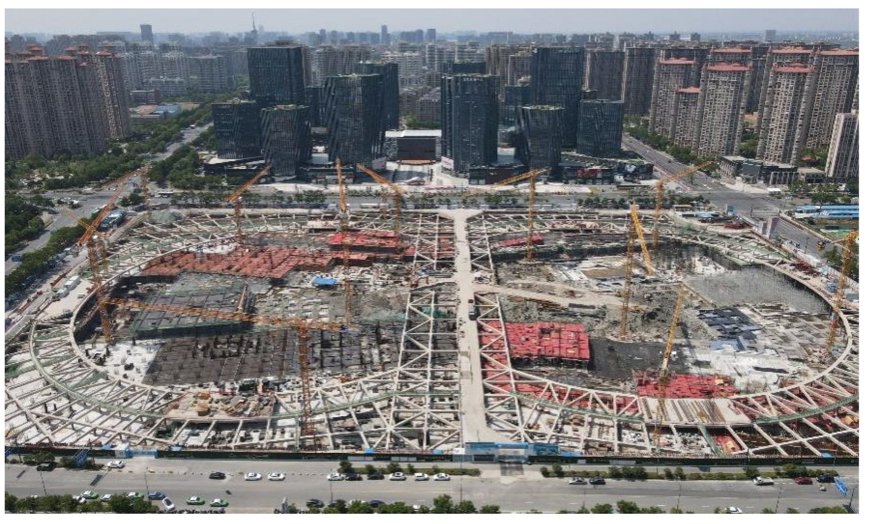
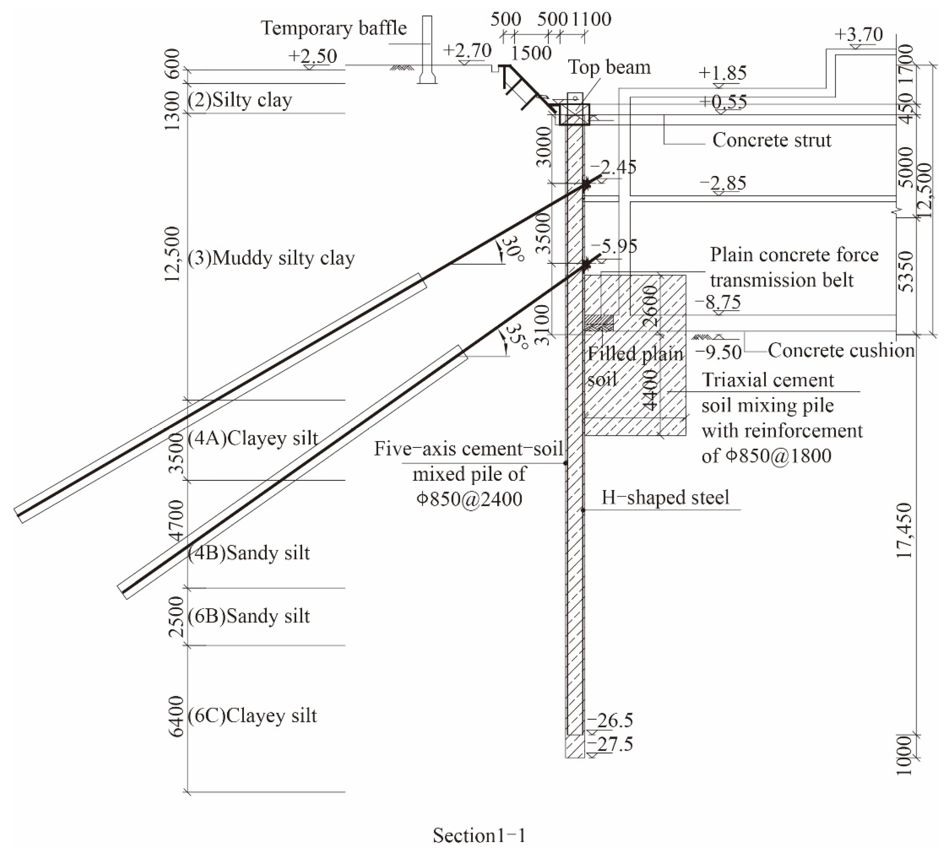
Considering the depth of the foundation pit, the surrounding environment, and hydrogeological conditions to ensure the stability and deformation requirements during the excavation of the foundation pit, the pile–anchor–brace supporting system (including an SMW pile, one row of concrete braces, and two rows of pre-stressed anchor cables) was selected to support this foundation pit (as shown in Figure 1 and Figure 2).
3.2. SMW Pile
According to the characteristics of the foundation pit and the technical specification for a soil mixed wall [17], the diameter of the SMW pile was 850 mm and the size of the H-shaped steel was determined to be 700 mm × 300 mm. Finally, soil-cement pile mixed by five shafts and by three shafts inserted with H700 type steel were used in the foundation pit.
3.3. Concrete Brace
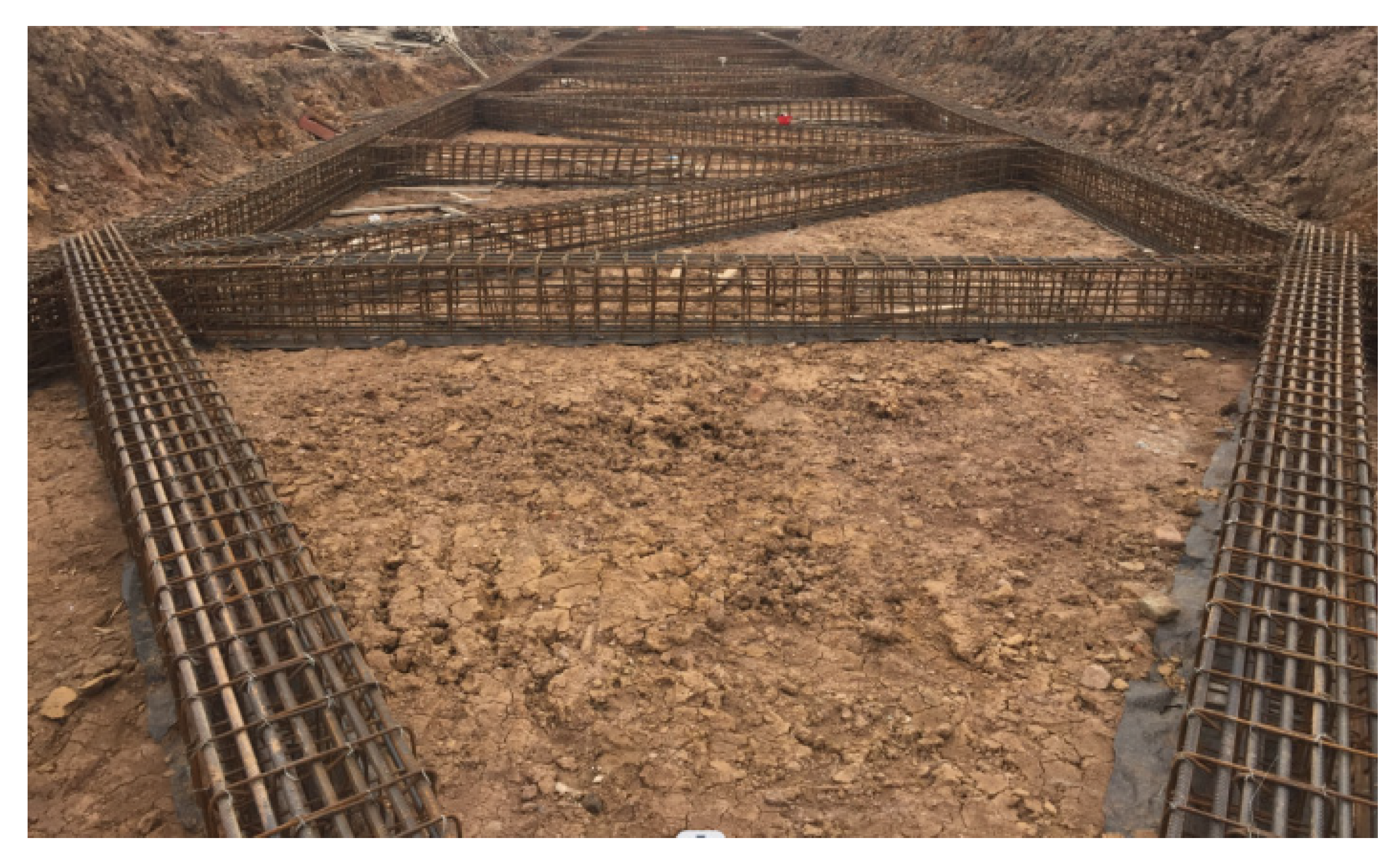
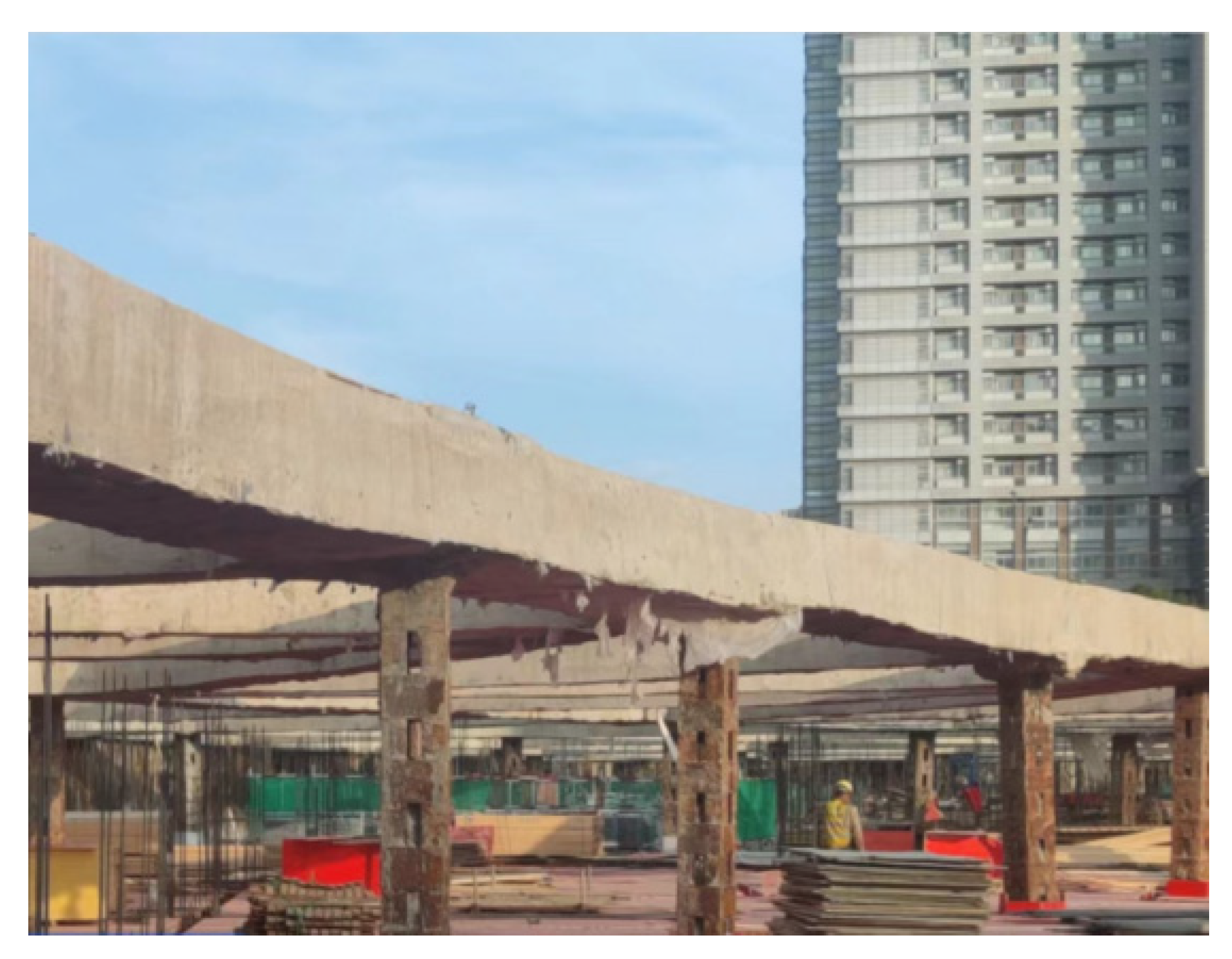
In order to enable the supporting structure to better transfer its load and maintain the stability and safety of the foundation pit, and for the comprehensive consideration of the shape and size of the foundation pit [18], an internal brace system including an opposite brace, diagonal brace, corner brace, and ring brace was finally adopted. The parameters of each brace section are shown in Table 2. The concrete grade and reinforcement grade in the table are determined according to the Code for Design of Concrete Structures GB50204-2015 [19]. Figure 3 shows the steel bar binding for opposite brace types and Figure 4 shows the ring brace after construction.
3.4. Rotary Spray Anchor Cable
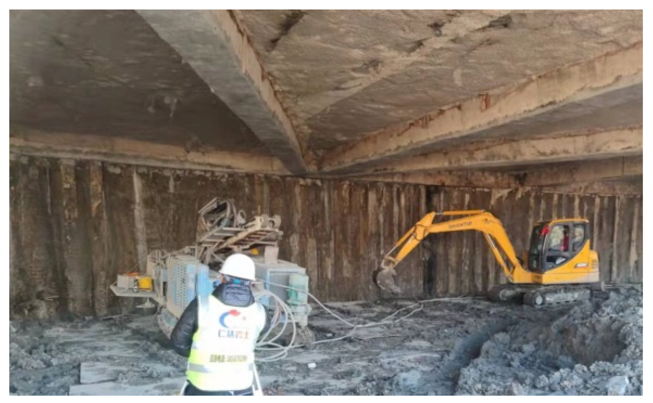
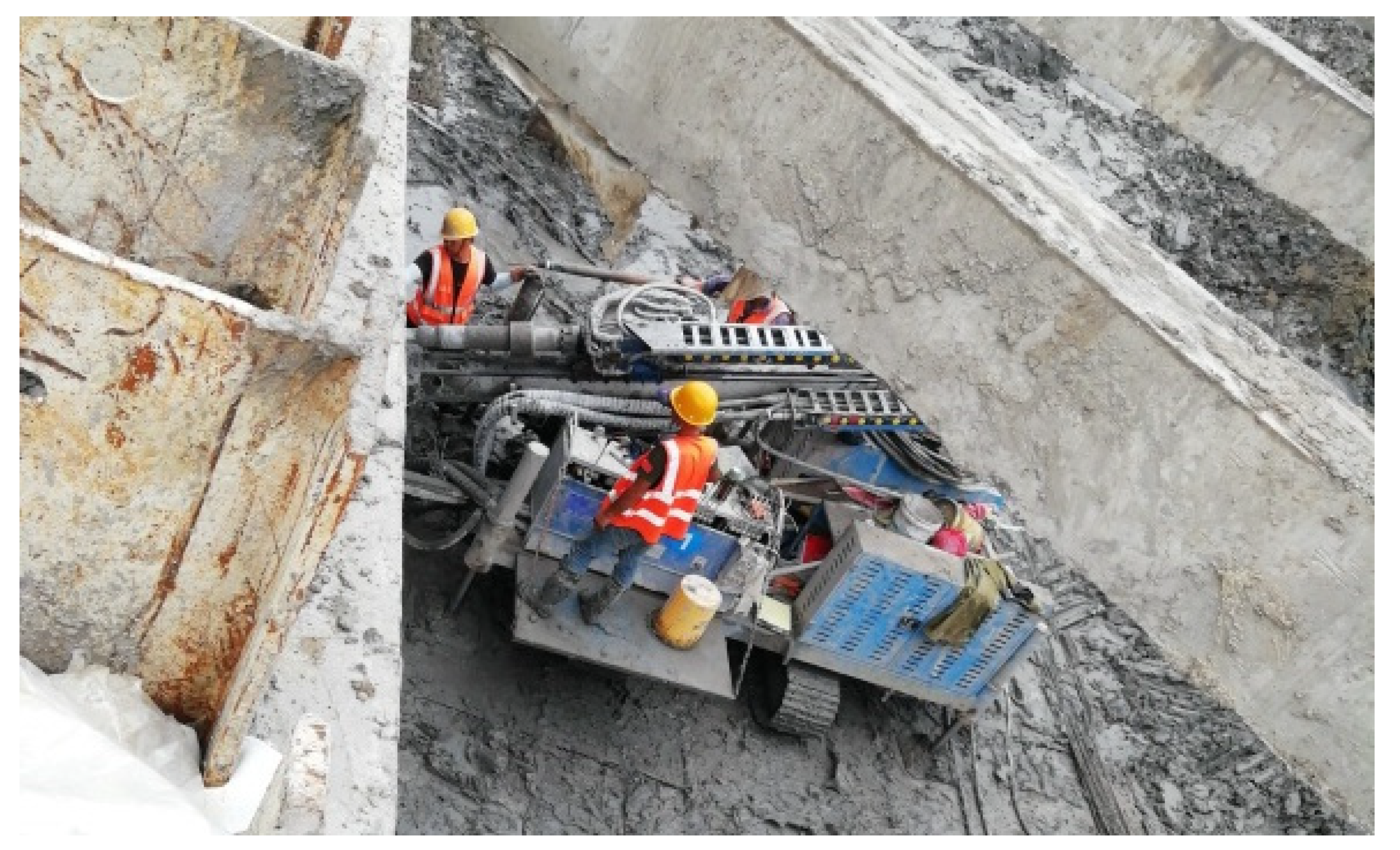
The project was located in a soft soil area. Considering the stress and load transfer of the anchor cable in soft soil and according to the requirements of the Technical Specification for Building Foundation Pit Support [20], a large-diameter rotary jet anchor cable was selected to support the foundation pit. Both of the two rows of anchor cables are composed of four bundles of steel strands with a nominal diameter of 15.2 mm and the diameter of each anchor cable is 500 mm. The other parameters of the anchor cables are shown in Table 3. The construction of drilling and grouting of the anchor cables can be seen in Figure 5 and Figure 6.
3.5. Work Conditions
It took about 13 months from the excavation of the foundation pit to the completion of the underground structure. As the foundation pit safety can be ensured after the brace replacement conditions are formed for the construction of the underground second floor roof, this paper only introduces the monitoring results from the beginning of excavation to the completion of the construction of the underground second floor roof. All of the processes can be divided into five work conditions, as shown in Table 4.
In the first work condition, the soil in the area of the inner brace was excavated at first and the soil was used as the framework for inner brace pouring. After the construction of the inner brace was completed and the design strength was reached, the excavation of other areas was carried out. In the second and third working conditions, the area around the anchor cable was excavated first, and then the anchor cable was constructed. Large-area excavation was carried out after the construction of the anchor cables was completed and the prestress was applied.
4. On-Site Monitoring and Data Analysis
The layout of the foundation pit monitoring points is shown in Figure 7. According to the foundation pit design drawings and the Technical Standards for Monitoring of Building Foundation Pit Engineering, there were 65 monitoring points for horizontal displacement of the pile top, which were numbered with QLi, and i was 1 to 65. They were arranged at the top of the coping beam with a spacing of 20 m. There were 26 monitoring points for deep horizontal displacement of the soil, which were numbered with CXi, and i was 1 to 26. They were buried in the soil around the foundation pit. There were 26 monitoring points for the groundwater level outside the foundation pit, which were numbered with SWi, and i was 1 to 26. They were buried in the soil around the foundation pit with a depth of 15 m. There were 62 monitoring points for road settlement, which were numbered with DLi, and i was 1 to 62. They were arranged at a distance of 20 m along the roadside adjacent to the foundation pit. There were 27 monitoring points for the axial force of brace, which were numbered with ZLi, and i was 1 to 27. They were laid on the braces. There were 28 monitoring points for the axial force of the anchor cables, which were numbered with MSi, and i is 1 to 28. They were divided into two rows and arranged near the anchor head.
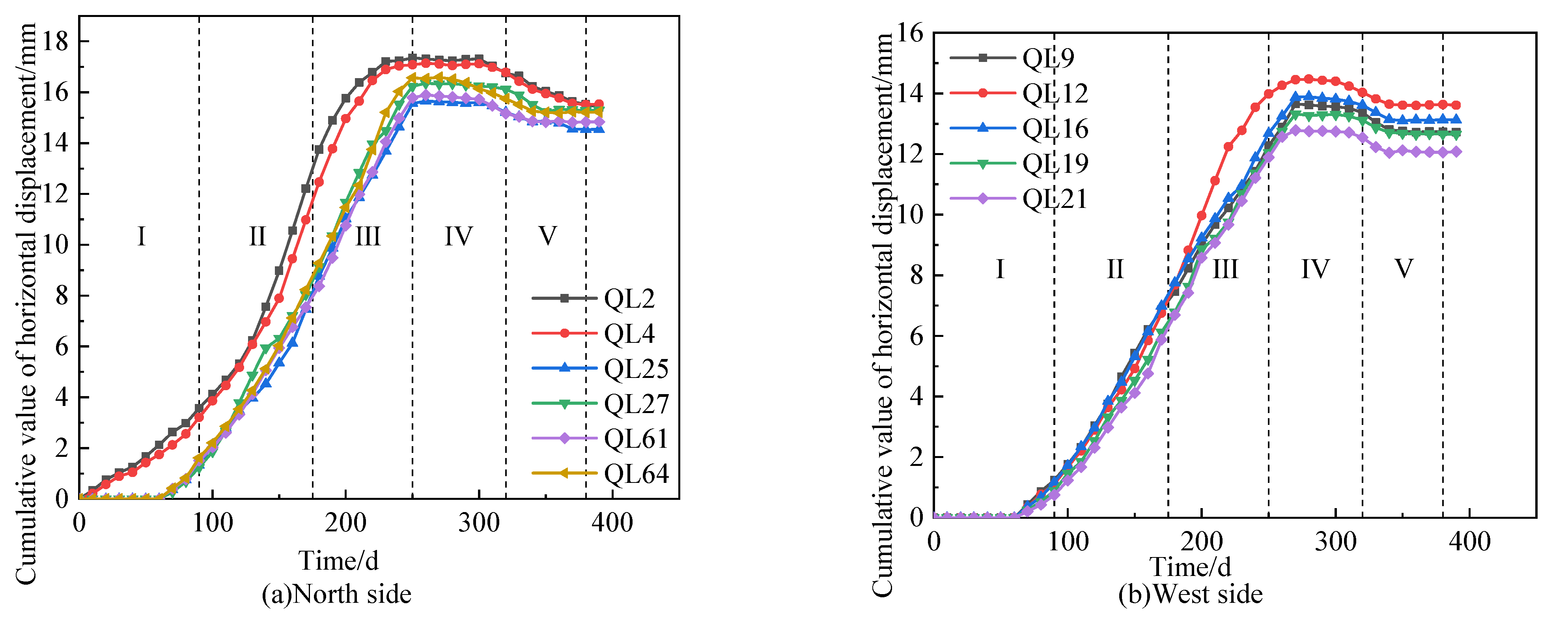
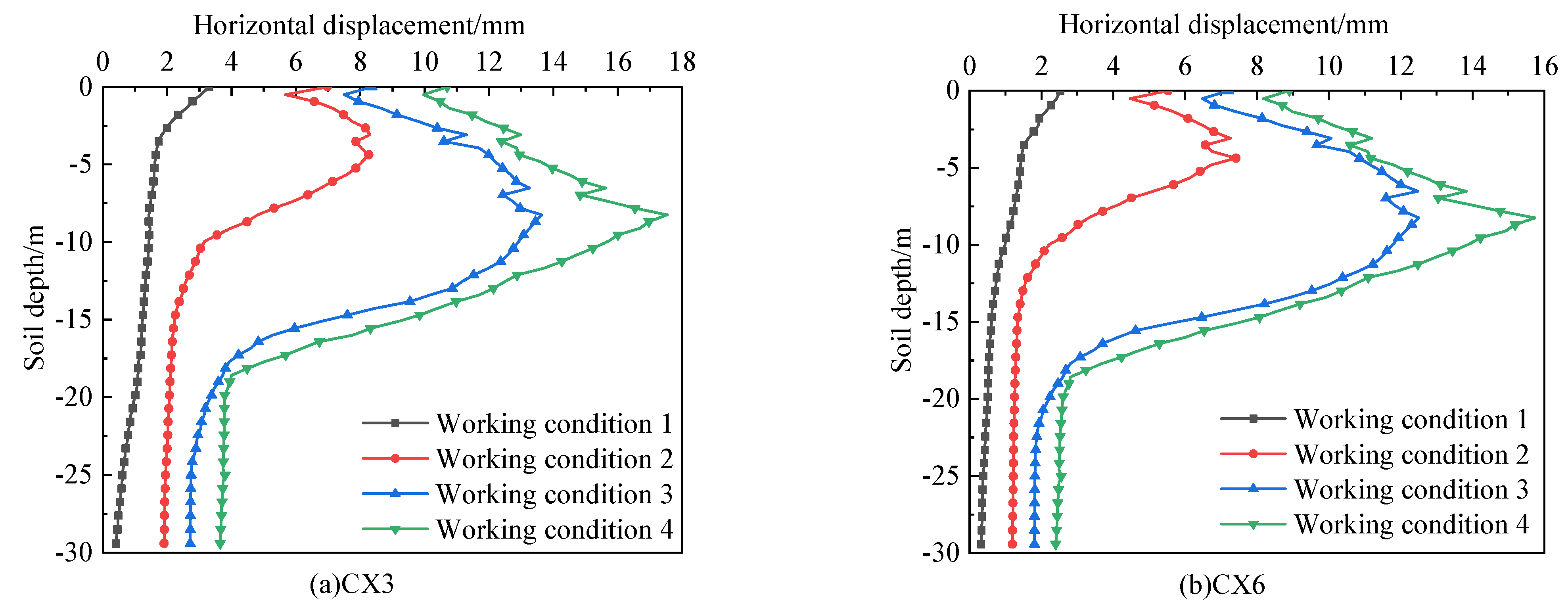
The horizontal displacement monitoring points on the north side and on the west side were selected. Because the construction progress of both sides of the foundation pit was relatively fast, their results can be compared and studied. The monitoring points of the axial force of the brace were respectively selected on the opposite brace, angle brace, and circular brace, which made it convenient to study the various types of braces. The remaining monitoring points were arranged on four sides of the foundation pit, so as to facilitate mutual comparison and research. The monitoring results of the horizontal displacement of the pile top, deep horizontal displacement, underground water level outside the pit, road settlement, support axial force, and anchor cable axial force can be found in Figure 8, Figure 9, Figure 10, Figure 11, Figure 12 and Figure 13.
4.1. Horizontal Displacement of the Pile Top
Figure 8 is the horizontal displacement curve of the pile top, where a positive value indicates that the displacement faces towards the inside of the foundation pit. The Roman numerals in the figures correspond to the working conditions of each stage and are reflected in the subsequent figures.
In the early stages of excavation, the horizontal displacement increment of each pile top was increased alternately without obvious differences, and the displacement variation was within 2 mm (before the 90th day). With the increase in the excavation depth, the horizontal displacement increased gradually, and the displacement change was between 2 mm and 17 mm (from the 90th day and the 250th day). The horizontal displacement tended to be stable after the completion of foundation slab construction (from the 250th day and the 320th day). During the construction of the underground structure inside the foundation pit, the horizontal displacement decreases (reverse displacement towards the outside of the pit appeared). This is because the underground structure construction imposes additional vertical stress on the soil inside the pit, which forced the pile to move towards the outside of the pit.
During the excavation of the foundation pit, the displacement of the pile top shows an obvious spatial effect [21]. In general, no matter on the long side or on the short side, the displacement of the middle part is large, and the pit angle is small. The closer the pit angle is, the smaller the displacement is. However, QL2 and QL4 in the northwest corner (as shown in Figure 7) did not follow the above rules. The reasons for these phenomena are as follows: (1) the excavation of the two areas was earlier than that of other areas, so the displacement of the pile top occurred earlier and faster than that of other areas, and (2) the pile top position of the two was constrained by the corner brace, which was slightly weaker than the ability of the opposite brace and the diagonal brace to constrain the deformation of the pile top. Among all monitoring points, the maximum horizontal displacement on the north side appeared in QL2, which was 17.35 mm, and 14.47 mm (in QL12) was the maximum horizontal displacement on the west side. There is an obvious difference between the two values, and the average horizontal displacement of the long side is greater than that of the short side.
4.2. Deep Horizontal Displacement of the Soil
Figure 9 shows the variation curve of the horizontal displacement of the soil along the depth direction. The monitoring points were arranged near the pile, and the positive value indicates that the deformation direction is toward the inside of the foundation pit.
It can be seen from Figure 9 that under work condition 1, the deep horizontal displacement of the two monitoring points mainly occurred above the inner brace. This is because the lower soil mass had not been excavated yet, and the supporting pile acted as the cantilever pile under the action of the brace. When it comes to work condition 2, the soil displacement mainly occurred in the soil layers 10 m below the surface, and the maximum displacement appeared at about 5 m below the surface. Under this work condition, the soil should have been excavated to 0.5 m below the first anchor cable, but due to the long construction period of the anchor cable, over-excavation was carried out, resulting in a further increase in the soil displacement and deepening of the overall soil displacement. For work condition 3, the soil displacement was further expanded in comparison to condition 2, and the overall displacement also developed deeper. Similar to condition 2, condition 3 also had a certain degree of over-excavation. Finally, for work condition 4, the overall horizontal displacement of the soil was bigger than condition 3, the maximum value of the horizontal displacement of the soil appears in the position of 8 m below the surface, and the trend of the curve was also close to condition 3. The reason for the increase in the overall horizontal displacement Is that the soil stress was continuously released from condition 3 to condition 4, which led to a further increase in the displacement of the soil. The reason why the two trends are close is that the foundation mat has been poured under condition 4, and the over-excavated surface of condition 3 is also close to the bottom of the foundation pit.
In addition, the development trend of the deep horizontal displacement of the soil at monitoring points CX3 and CX6 was basically the same. At the beginning, they all showed a ‘cantilever’ shape, and then they showed a ‘drum belly’ shape with the working conditions that were going on. The average value of the overall horizontal displacement of CX3 is larger than that of CX6. This is because monitoring point CX3 is on the long side and CX6 is on the short side. The spatial effect causes the difference between the two values.
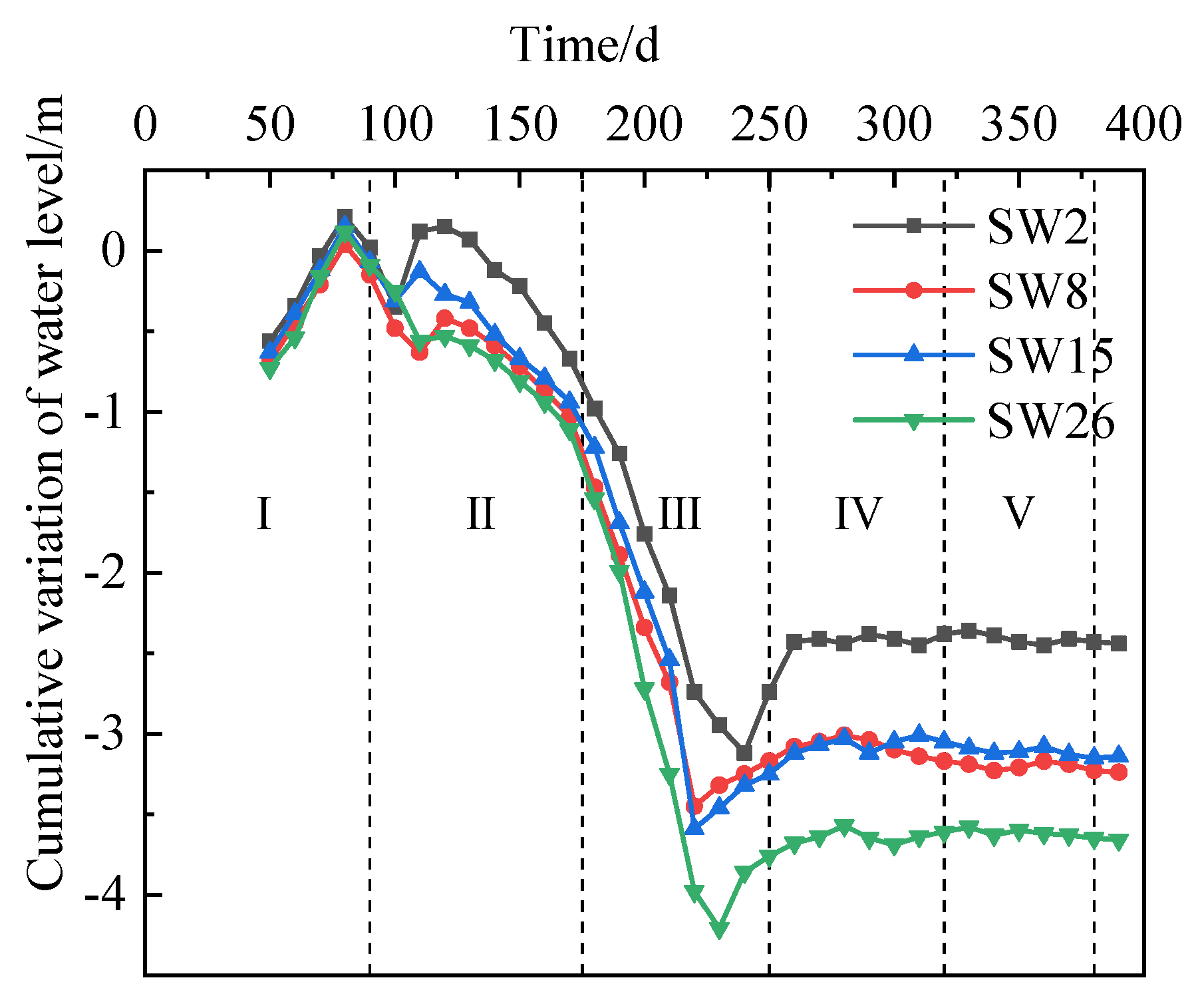
4.3. Groundwater Level Outside the Foundation Pit
Figure 10 shows the curve of the underground water level outside the pit with time. In work condition 1 (before the 90th day), the depth of the lowered groundwater level in the pit is small, which has little impact on the groundwater level outside the pit. This condition happened to be in the rainy season, and there was more precipitation during the construction period, so the groundwater level rose. As the groundwater level in the pit continues to decrease, the groundwater level outside the pit also decreases.
It should be noted that the construction of two rows of anchor cables pierced the waterproof curtain of the foundation pit (from the 90th day and 250th day). Due to the high water head outside the pit, water leakage and sand leakage occurred at the site, of which the water leakage and sand leakage at the east side were serious. The range of the water level change was within 5 m.
With the treatment of water leakage and sand leakage, the groundwater level outside the pit gradually became stable (from the 250th day and the 380th day). Due to the differences in stratum distribution, the final groundwater level around the foundation pit was different. The groundwater level on the east side of the foundation pit was the shallowest (4.8 m below the surface), while the groundwater level on the north side of the foundation pit was the highest (3.5 m below the surface), and the west and south sides of the foundation pit were in the middle.
The warning value of the water level change is 1 m. Although the warning value had been greatly exceeded during the construction period, the project has not been greatly affected due to timely and appropriate treatment measures.
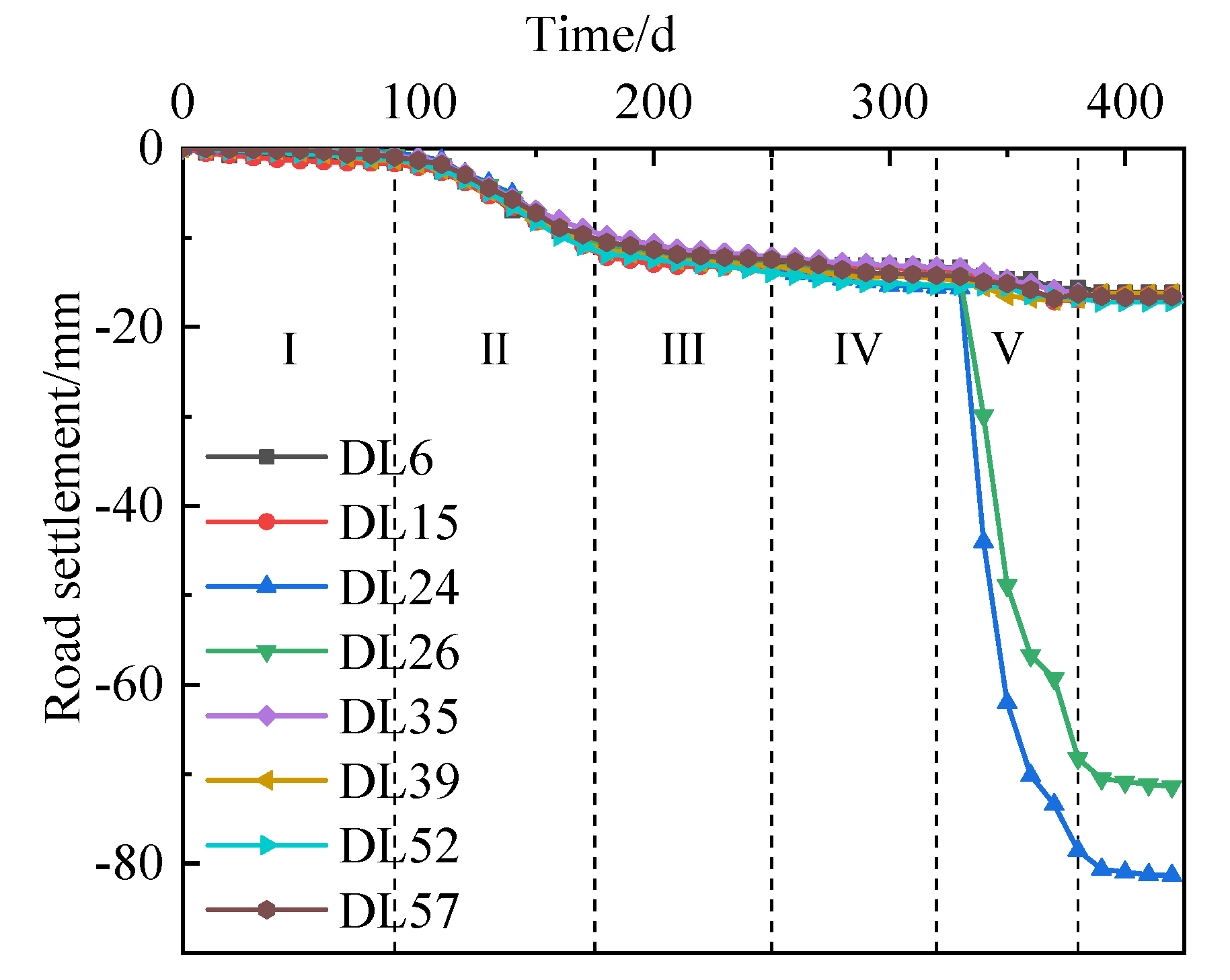
4.4. Road Settlement
Figure 11 is the road settlement curve. In the early stage of excavation, the settlement of the road around this foundation pit increased slowly. During the construction of the first row of anchor cables (in working condition 2), the largest road settlement reached to −15 mm, which was smaller than the alarm value (20 mm), and results of all monitoring points have the same change rule. However, the road settlements of different monitoring points showed obvious differences with the construction of the second row of anchor cables (working condition 3). At this stage, the settlement of the east road increased rapidly; the cumulative settlement of monitoring point DL24 on the east side of the foundation pit reached −80.64 mm from −17.35 mm, which accounted for 89.6% of the total settlement. while the roads settlement of the other three sides of this foundation pit showed a trend of steady growth.
The main reason for the difference in settlement is that relatively serious water leakage and sand leakage occurred during the construction of the second anchor cable on the east side. The flow of water and soil from outside into the pit provided space for road settlement outside the pit. In addition, the road on the east side is the main urban road with a large traffic flow and large additional load, which also aggravated the rapid increase in road settlement. With the effective disposal of the water leakage and sand leakage, the road settlement was stable after the completion of the second anchor cable construction, and the development of road settlement for the east side was not obvious under the fourth working condition. Although the total settlement value of the east side road exceeded the alarm value, this phenomenon did not have a significant impact on the entire project due to the implementation of road maintenance, the control of precipitation outside the foundation pit, and the setting of warning signs to prohibit the operation of large vehicles and heavy vehicles.
4.5. Axial Force of Brace
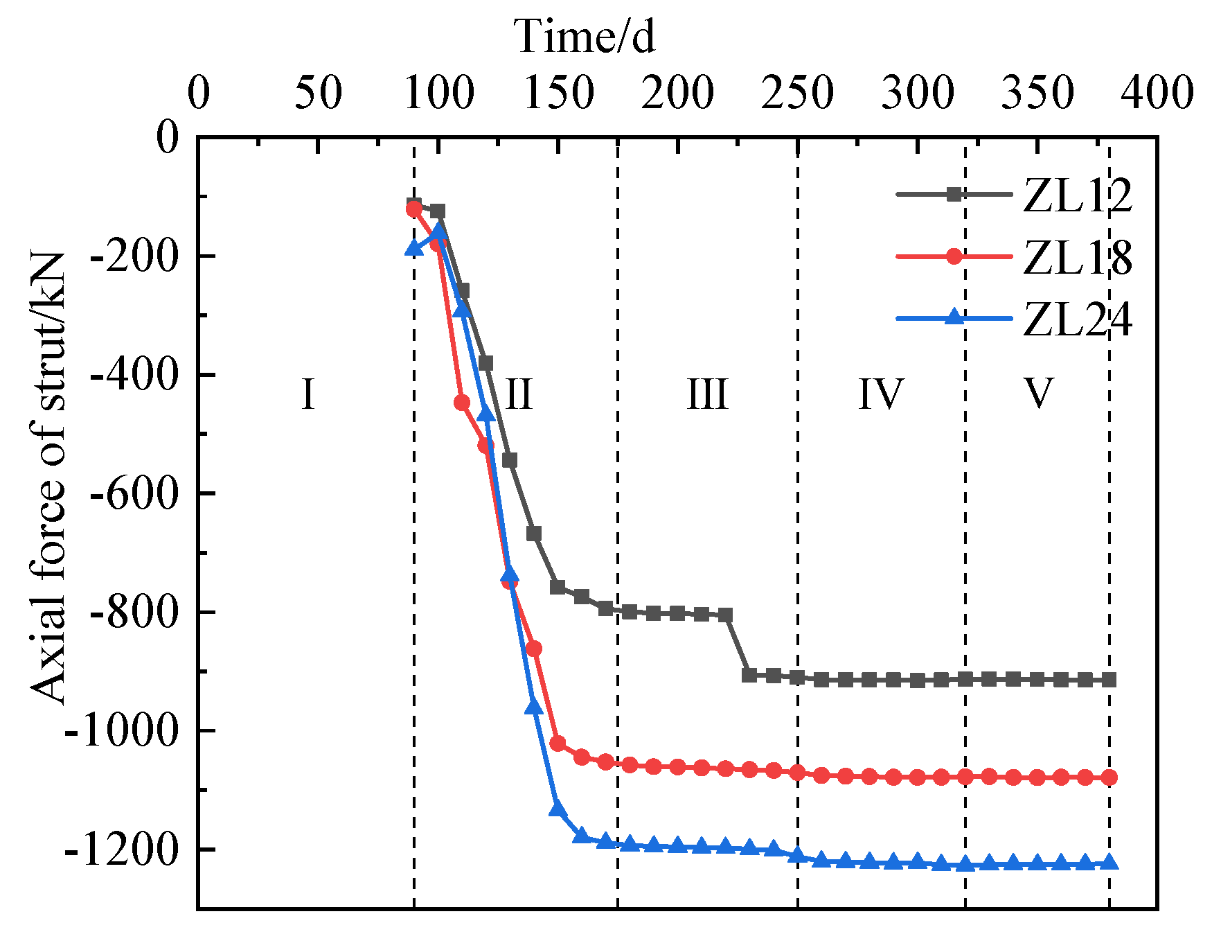
Figure 12 shows the change curve of brace axial force, in which a negative value means pressure. The monitoring of the axial force of the brace began in work condition 2, so all the curves started from the 90th day.
Axial force of all kinds of braces during work condition 2 (dig the second layer of soil to 6.5 m below the surface and construct the first row of anchor cable) grew rapidly However, for the work condition 3 (dig the third layer of soil to 9.5 m below the surface and construct the second row of anchor cable), the axial force remained stable and no longer increased. The reasons for this phenomenon may be as follows: at the beginning of excavation of the soil below the brace, the support structure of the foundation pit bore more unbalanced earth pressure. Since the anchor cable had not been constructed yet, the braces had to bear more force. With the completion of the construction of the first row of anchor cables, the unbalanced earth pressure caused by the excavation of the soil under the first row of anchor cables was borne by the anchor cable. At this time, the axial force would not change any more. So, the following conclusion can be drawn whereby the excavation of the foundation pit will only increase the axial force of the adjacent braces or anchor cable and will not affect the axial force of remote braces and anchor cables.
Among all kinds of braces, the axial force of the ring brace is the largest, reaching about 1250 kN, the opposite brace is the smallest, about 910 kN, and the angle brace is in the middle, about 1080 kN. Generally, the axial force of the opposite brace should be the maximum, but the excavation road is arranged on the opposite brace of this foundation pit, which was partially strengthened, so the maximum axial force appeared on the ring brace.
4.6. Axial Force of Anchor Cables
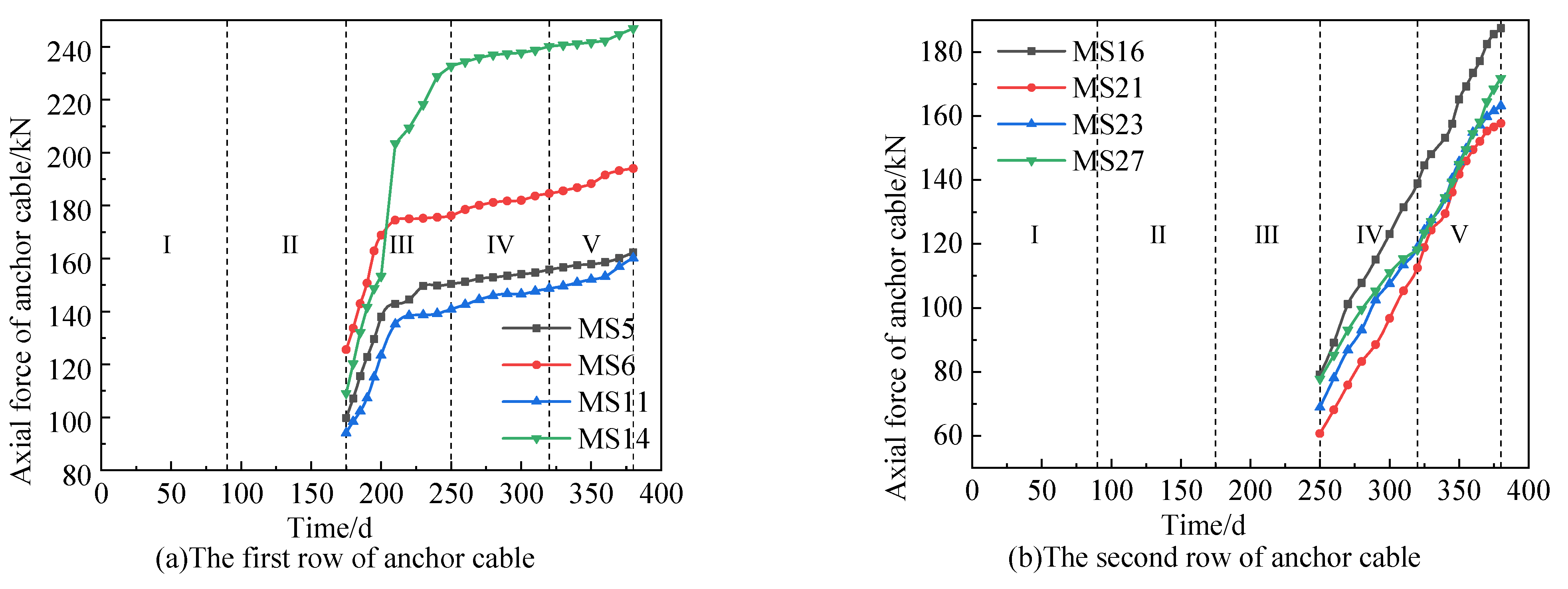
Figure 13 shows the change curve of axial force for the anchor cables. Since the monitoring of the axial force of the first row and the second row of anchor cables started in work condition 3 and work condition 4, the monitoring results of anchor cables were introduced from the 175th day and 250th day. It can be seen from Figure 13 that the axial force of the first row of anchor cables is generally greater than that of the second row of anchor cables. This is because during work condition 2, the water leakage and sand leakage reduced the water and soil pressure outside the foundation pit at the position of the second row of anchor cables.
With the excavation of the soil below the second row of anchor cables, the axial force of the first row of anchor cables tended to be stable, while the axial force of the second row of anchor cables increased, which is consistent with the conclusion in Section 3.5. After excavation to the bottom of the foundation pit, the axial force of the second row of anchor cables still increased, which was related to the time effect of the foundation pit. The soil outside the pit needed time to consolidate and deposit after construction disturbance.
According to the statistics of the results of all measuring points for anchor cables, it can be seen that the axial force of the first row of anchor cables ranged from 97.5 to 245.7 kN, and their average axial force was 171.6 kN, which is only 66% of the designed axial force (260 kN). The axial force of the second row of anchor cable varied from 62.4 to 187.5 kN, with an average of 124.9 kN, which is only 60.95% of its designed value (205 kN).
The maximum axial force of the two rows of anchor cables did not exceed the design value and there was a large margin, indicating that the anchor cables in some soil layers in soft soil areas can still play a very good supporting role and can be used as an alternative structure for foundation pit support in soft soil areas.
5. Conclusions
Based on the foundation pit engineering supported by the pile–anchor–brace supporting system in Yancheng City, Jiangsu Province, China, the following conclusions can be drawn through the analysis of the design and on-site monitoring of the pile–anchor–brace supporting system:
- (1)
- The deformation of the foundation pit supported by the pile–anchor–brace supporting system also has an obvious spatial effect. The deformation of the supporting system in the middle of the foundation pit is greater than that in the corner and the deformation of long side of foundation pit is greater than of the short side. Therefore, the deformation monitoring of the supporting system in the middle part of the foundation pit should be strengthened in the process of construction.
- (2)
- The deep horizontal displacement of the soil in the foundation pit supported by the pile–anchor–brace supporting system is initially in the shape of a ‘cantilever’. With the advance of foundation pit excavation, it gradually presents a ’bulge‘ shape. At the position with the inner brace and anchor cable, the horizontal displacement has an obvious sudden change.
- (3)
- The brace axial force would increase rapidly before the construction of anchor cable, but after the completion of the first anchor cable construction, the axial force would gradually become gentle. The axial force of the ring brace is larger than the corner brace, which is larger than the opposite brace.
- (4)
- The change trend of the axial force of the two rows of anchor cables is different. The accumulated axial force of the first anchor cable is large and tends to be gentle after the foundation mat is poured, while the change in the axial force of the second row of anchor cables is relatively gentle. The axial force of the first row of anchor cables is generally greater than the second row. The axial force of the two anchor cables does not exceed their design value, so it can be used as a reference for other projects.
Author Contributions
Conceptualization, L.S. and G.X.; methodology, G.D.; validation, J.S., T.S. and S.Y.; formal analysis, K.M.; investigation, J.S.; resources, L.S.; data curation, G.X.; writing—original draft preparation, K.M.; writing—review and editing, Z.W.; supervision, G.D.; project administration, L.S.; funding acquisi-tion, Z.W. All authors have read and agreed to the published version of the manuscript.
Funding
This work was supported by the National Natural Science Foundation of China (Grant No. 52068048), Technology Project of Gansu Provincial Department of Housing and Urban-Rural Development Construction (Grant No. JK2022-03), Natural Science Foundation of Gansu Province (Grant No. 21JR11RM052), Youth Science and Technology Fund Program of Gansu Province (Grant No. 22JR5RA286), and the Hongliu Excellent Young Talents Program of Lanzhou University of Technology.
Data Availability Statement
The data of monitoring in the article is not freely available due to legal concerns and commercial confidentiality. Nevertheless, all the concepts and procedures are explained in the presented research and parts of the research may be available upon request.
Conflicts of Interest
The authors declare no conflict of interest.
References
- Clough, G.W.; O’Rourke, T.D. Construction induced movements of in situ wall. In Design and Performance of Earth Retaining Structures; Geotechnical Special Publication; American Society of Civil Engineers (ASCE): Reston, VA, USA, 1990; pp. 439–470. [Google Scholar]
- Mana, A.I.; Clough, G.W. Prediction of movement for braced cut in clay. J. Geotech. Eng. Div. 1981, 107, 759–777. [Google Scholar] [CrossRef]
- Ou, C.Y.; Hsieh, P.G.; Chiou, D.C. Characteristics of ground surface settlement during excavation. Can. Geotech. J. 1993, 30, 758–767. [Google Scholar] [CrossRef]
- Hashash, M.A.; Whittle, A.J. Ground movement prediction for deep excavations in soft clay. J. Geotech. Eng. 1996, 122, 474–486. [Google Scholar] [CrossRef]
- Yang, Z.H.; Guo, Z.X. Monitoring analysis of pre-stressed load of anchor cables for deep excavations. Chin. J. Geotech. Eng. 2012, 34, 145–148. [Google Scholar]
- Ju, C.; Li, J.C.; Zhou, X.J. Analysis of foundation pit supporting design and monitoring results in deep saturated soft soil area. Build. Sci. 2012, 28, 107–110. [Google Scholar]
- Xu, W.; Xia, Q.W.; Xu, P.F.; Wang, J.F. Monitoring and analysis of synchronized excavation of extra large-scale adjacent riverside deep foundation pits in soft soil. Chin. J. Rock Mech. Eng. 2013, 32, 2676–2683. [Google Scholar]
- Li, X.L.; Wei, X.; Liang, Z.R. Design practice and analysis of deformation control of deep excavations in soft soil areas. Chin. J. Geotech. Eng. 2014, 36, 160–164. [Google Scholar]
- Zhang, Y.J.; Zeng, J.W. Dynamic monitoring and emergency treatment of deep foundation pit in ultra deep silt layer. Chin. J. Geotech. Eng. 2014, 36, 202–207. [Google Scholar]
- Gong, H.; Xiong, Z.B.; Song, S.H.; Dai, W.K.; Wang, R.J. Structural design and monitoring analysis of deep foundation pit supporting under complex surroundings. Chin. J. Undergr. Space Eng. 2015, 11, 732–738. [Google Scholar]
- Wei, G.; Hua, X.X.; Yu, X.F. Construction monitoring analysis of deep foundation pit excavation of a metro station in Hangzhou. Eng. J. Wuhan Univ. 2016, 49, 917–923. [Google Scholar]
- Li, Y.B.; Dong, W.; Wang, B. Monitoring and analyzing deformation characteristics for deep foundation pit in soft soil area. Bull. Surv. Mapp. 2017, 2017, 116–120. [Google Scholar]
- Li, K.X.; Yang, Z.N.; Li, S.C. Monitoring analysis of deep foundation pit of shield launching section of highway tunnel in soft soil area. Highway 2017, 62, 282–288. [Google Scholar]
- Jiang, J.; Xiao, M.; Liu, Z.Y.; Wang, Z.; Zhang, X.C.; Yang, D. Monitoring of deep foundation pit with a combination of various supporting systems under complicated environment. J. Guangxi Univ. 2018, 43, 269–278. [Google Scholar]
- Long, L.; Li, Z.D. Monitoring and deformation law research of a deep foundation pit project in Changsha. Build. Struct. 2020, 50, 133–137. [Google Scholar]
- Yancheng: Jiangsu Wanda Survey and Detection Design Co., Ltd. Investigation Report of Yancheng First People’s Hospital Phase II and Medical Complex Project; Yancheng Publishing House: Yancheng, China, 2022. [Google Scholar]
- JGJ/T 199-2010; Technical Specification for Soil Mixed Wall. Architecture Press: Beijing, China, 2010.
- Liu, G.B.; Wang, W.D. Manual for Foundation Pit Engineering, 2nd ed.; Architecture Press: Beijing, China, 2009. [Google Scholar]
- GB50010-2010; Code of Design of Concrete Structures. Architecture Press: Beijing, China, 2015.
- China Academy of Building Sciences. Technical Specification for Retaining and Protection of Building Foundation Excavations; Architecture Press: Beijing, China, 2012. [Google Scholar]
- Li, D.P.; Tang, D.G.; Yan, F.G.; Huang, M. Mechanics of deep excavation’s spatial effect and pressure calculation method considering its influence. J. Zhejiang Univ. 2014, 48, 1632–1639. [Google Scholar]
Figure 1.
Aerial photograph of the foundation pit.

Figure 2.
Typical support section (unit: mm).

Figure 3.
Steel bar binding of the inner brace.

Figure 4.
Ring brace.

Figure 5.
Drilling of the anchor cables.

Figure 6.
Grouting of anchor cables.

Figure 7.
Layout of the monitoring points.

Figure 8.
Horizontal displacement curve of the pile top.

Figure 9.
Deep horizontal displacement curve.

Figure 10.
Change curve of the groundwater level outside the pit.

Figure 11.
Road settlement curve.

Figure 12.
Variation curve of the axial force of the brace.

Figure 13.
Variation curve of the axial force of the anchor cable.


Table 1.
Basic parameters of each rock and soil layer.
| Soil Layer Sequence | Layer Name | Depth of Soil Layer/m | γ/(kN/m3) | ω/(%) | c’/kPa | φ’/(°) |
|---|---|---|---|---|---|---|
| Layer 1 | Plain fill (Q4m1) | 0.10~1.10 | 17.5 | / | 8.0 | 10.0 |
| Layer 2 | Silty clay (Q4l) | 1.30~2.20 | 18.9 | 29.9 | 20.7 | 8.1 |
| Layer 3 | Muddy silty clay (Q4l) | 12.20~19.20 | 17.3 | 43.7 | 12.5 | 7.1 |
| Layer 4A | Clayey silt (Q4m) | 13.80~19.50 | 18.3 | 32.6 | 14.7 | 14.2 |
| Layer 4B | Sandy silt (Q4m) | 15.00~22.80 | 19.0 | 28.1 | 8.3 | 27.4 |
| Layer 5 | Clayey silt (Q4m) | 18.20~24.10 | 18.3 | 33.3 | 14.8 | 16.8 |
| Layer 6A | Clayey silt (Q4m) | 18.40~24.00 | 18.3 | 32.9 | 13.8 | 17.0 |
| Layer 6B | Sandy silt (Q4m) | 21.70~25.70 | 18.9 | 28.9 | 8.2 | 27.0 |
| Layer 6C | Clayey silt (Q4m) | 24.50~26.00 | 18.4 | 32.1 | 14.9 | 18.0 |
Note: (Definitions: γ is soil weight, ω is soil moisture content, c’ is soil cohesion force, and φ’ is the angle of internal friction).
Table 2.
Sectional parameters of the braces.
| Type of Brace | Concrete Grade | Sectional Height/mm | Section Width/mm | Reinforcement of Top of Brace | Reinforcement of Bottom of Brace | Longitudinal Stirrup | Lateral Stirrup |
|---|---|---|---|---|---|---|---|
| Opposite brace | C30 | 900 | 800 | 6C25 | 6C25 | C8@200/400 | C8@100/200 |
| Top beam | C30 | 900 | 1300 | 6C20 | 8C20 | 4C8@300 | 4C8@150 |
| Inner ring brace | C30 | 900 | 1400 | 6C20 | 8C20 | 4C8@300 | 4C8@150 |
| Outer ring brace | C30 | 900 | 1300 | 6C20 | 8C20 | 4C8@300 | 4C8@150 |
| Coupling beam | C30 | 900 | 700 | 5C25 | 5C25 | C8@200/400 | C8@100/200 |
Table 3.
Parameters of the anchor cables.
| Vertical Position | Dip Angle/(°) | Length of Free Section/m | Anchoring Length/m | Design Value of Axial Force for Anchor Cable/kN | Prestress of Anchor Cable/kN |
|---|---|---|---|---|---|
| First row | 30 | 9 | 23 | 260 | 300 |
| Second row | 35 | 6 | 22 | 205 | 200 |
Table 4.
Work conditions.
| Work Condition | Specific Construction Stage | Duration of Experience |
|---|---|---|
| I | Dig the first layer of soil to 3.5 m below the surface and construct the inner brace | 90 d |
| II | Dig the second layer of soil to 6.5 m below the surface and construct the first row of anchor cables | 85 d |
| III | Dig the third layer of soil to 9.5 m below the surface and construct the second row of anchor cables | 75 d |
| IV | Dig the fourth layer of soil to 12 m below the surface and pour the cushion and floor | 70 d |
| V | Construct underground structure to the negative two-layer roof | 60 d |
Publisher’s Note: MDPI stays neutral with regard to jurisdictional claims in published maps and institutional affiliations. |
© 2022 by the authors. Licensee MDPI, Basel, Switzerland. This article is an open access article distributed under the terms and conditions of the Creative Commons Attribution (CC BY) license (https://creativecommons.org/licenses/by/4.0/).
Share and Cite
MDPI and ACS Style
Sun, L.; Mao, K.; Wang, Z.; Ye, S.; Su, T.; Dai, G.; Xu, G.; Sun, J. Design and Field Monitoring of a Pile–Anchor–Brace Supporting System in a Soft Soil Area. Water 2022, 14, 3949. https://doi.org/10.3390/w14233949
AMA Style
Sun L, Mao K, Wang Z, Ye S, Su T, Dai G, Xu G, Sun J. Design and Field Monitoring of a Pile–Anchor–Brace Supporting System in a Soft Soil Area. Water. 2022; 14(23):3949. https://doi.org/10.3390/w14233949
Chicago/Turabian StyleSun, Lin, Ke Mao, Zhengzhen Wang, Shuaihua Ye, Tiantao Su, Guoliang Dai, Guangxiang Xu, and Jilong Sun. 2022. "Design and Field Monitoring of a Pile–Anchor–Brace Supporting System in a Soft Soil Area" Water 14, no. 23: 3949. https://doi.org/10.3390/w14233949
Note that from the first issue of 2016, this journal uses article numbers instead of page numbers. See further details here.