
Bioelectricity Generation and Decolorization of Reactive Blue 221 Using a Modified Cathode Dual-Chamber Microbial Fuel Cell

1
Department of Environmental Engineering, Civil & Environmental Engineering Faculty, Tarbiat Modares University, Tehran 14115-397, Iran
2
Department of Environmental Management, Natural Resources and Environment Faculty, Science and Research Branch, Islamic Azad University, Tehran 14778-93855, Iran
*
Author to whom correspondence should be addressed.
Water 2023, 15(1), 101; https://doi.org/10.3390/w15010101
Submission received: 21 November 2022
/
Revised: 20 December 2022
/
Accepted: 23 December 2022
/
Published: 28 December 2022
(This article belongs to the Special Issue Electronic Technology for Wastewater Treatment and Clean Water Production)
Abstract
:In this study, the simultaneous enzymatic decolorization of reactive blue 221 (RB221) and the performance of different electrode carbon nanotube (CNT)-modified/unmodified carbon graphite cathodes were investigated in a dual-chamber Microbial Fuel Cell (MFC) at a permanent temperature of 25 °C. The maximum power density and maximum voltage increased by approximately 13.6% and 50%, respectively, when using the CNT-modified carbon graphite electrode as the cathode. A suspended laccase enzyme was utilized in the cathode compartment for dye decolorization. In the absence of the dye, laccase caused an increase in power density to about 28%. In addition, this research revealed that an initial dye concentration of 80 mg/L simultaneously resulted in an enzymatic decolorization efficiency of 73.4% in the cathode chamber and 82.3% chemical oxygen demand (COD) removal of sucrose in the anode chamber. Finally, this study substantiates the fact that an MFC equipped with a CNT-modified carbon graphite electrode can be used for bioelectricity generation and effective dye removal.
1. Introduction
With their appropriate utilization, renewable energies are the premise of sustainable societal and monetary improvement and consist of accessible reusable gas assets that lessen dangerous environmental results and pollution [1]. Biofuels are options for the world’s upcoming electricity disaster attributable to exhaustible fossil fuels [2]. Meanwhile, bioelectrochemical structures such as microbial cells are novel technology for generating electricity from wastewater’s natural materials [3]. In 1911, Potter proposed the concept of an MFC system, wherein microorganisms emit electrons by means of the degradation of natural molecules via a chain of enzymes. The reduction of the terminal, known as an electron acceptor, happens by means of receiving the loose electrons. The anode chamber, which incorporates a microbial population, is used to preserve anaerobic conditions, given that oxygen prevents electron generation [4]. This MFC chamber is fed with many natural compounds, which include glucose [5], acetate [6], and molasses. The quantity of the electricity yield additionally pertains to the sort of wastewater. Previous works with MFC setups much like the one in this examination reported 274 mW/m2 [7], 583 mW/m2 [8], 800 mW/m2 [8], and 20 mW/m2 [9] electricity densities via the use of dye, ethanolamine, fabric wastewaters, and dairy wastewaters, respectively. However, because of excessive toxicity, few dye pollutants are degraded by means of organic or anodic oxidation processes [10]. Dyes are natural compounds that can be used to stain paper, leather, hair, wool, medicine, beauty supplies, candles, plastics, and fabric materials [11]. In general, in fabric industries, basic, acidic, reactive, direct, and azo dyes are the main broadly used forms of dyes, with over 50% annual consumption [12]. Carcinogenicity, excessive toxicity, and pollutant effects on the surroundings are reasons why the remediation of wastewater containing dyes is significant. Furthermore, dyes negatively affect the transparency and oxygen solubility of water and endanger aquatic life [13]. Dye effluents emitted from numerous dye industries pose a hazard to the surroundings, dwelling organisms, and consequently people, as previously mentioned. Nowadays, the presence of dye effluent in one-of-a-kind water matrices has turned out to be a prime environmental concern. In the same vein, dye in wastewater must be efficaciously dealt with prior to its emission into the surroundings to reduce its destructive results and thereby meet discharge regulations [14,15].
Many physical, chemical, and biological methods have been employed to remove dyes from aquatic environments, including electrocoagulation [16], electrodialysis [17], photo-catalysis [18], adsorption [19], and membrane approaches [20]. Despite the undeniable virtues of such technologies, they possess some drawbacks, such as byproduct creation, high energy requirements, additive chemicals, high maintenance costs, challenging scale-up, a lack of systematic reactors, and membrane fouling [21,22,23,24]. Photo-ozonation has also been demonstrated as another effective method of dye removal from wastewater [25]. Synthetic dye removal with oxidoreductases such as lignin peroxidase [26] and laccase from fungi [27] has recently been studied. Among the aforementioned enzymes and due to the lack of the necessity of hydrogen peroxide, laccase (p-diphenol oxidase, EC 1.10.3.2) has been widely considered. The catalytic properties of laccase enzymes give them great potential applications in different industries, such as dye decolorization and degradation in the textile industry [28]. In recent years, MFCs, as a versatile process in wastewater treatment addressing the two issues of pollutant removal and energy production simultaneously, have been the focus of attention [29]. The applicability of MFCs in wastewater treatment is limited due to their low-power-density production efficiency; the high over-potential of the cathode chamber is the main reason. Platinum (Pt) is ordinarily used as a catalyst in MFCs to eradicate the aforementioned obstacle [30,31]. However, the high cost of using it on a large scale has prompted many researchers to study economical non-noble metal materials to replace Pt as an electrode catalyst [32,33]. Recently, CNTs have been widely considered by researchers [34,35] in MFC studies due to their high catalytic activity, high corrosion resistance, high surface area, and lower material costs compared to other catalysts. They also simplify chemical reactions by readily interacting and functioning with various groups [36]. Their high catalytic activity is not only because of their ability to easily function with different groups and high surface areas but also due to their invariable dispersion of catalytic particles on the electrode surface [35]. Although the problem of collecting and dispersing nanoparticles in aquatic environments has not yet been solved, according to their properties, CNTs serve as photocatalysts in the chemical oxidation of non-organic pollutants in wastewater (dyes, for instance) and significantly affect water clarification [37].
In this study, a dual-chamber MFC with a CNT-modified cathode electrode and a fed-batch-mode anode chamber was used to investigate simultaneous dye decolorization (via an enzymatic reaction catalyzed by laccase) and energy production. The effects of the enzymatic degradation of RB221, different initial dye concentrations, and CNT-coated cathodes on MFC performance were studied by recording the produced voltage and current density data. To date, no studies have been performed on the effects of CNT-modified carbon graphite electrodes on enzymatic dye decolorization and bioenergy production in an MFC.
2. Materials and Methods
2.1. Materials
2.1.1. Microbial Fuel Cell Assembly and Operation
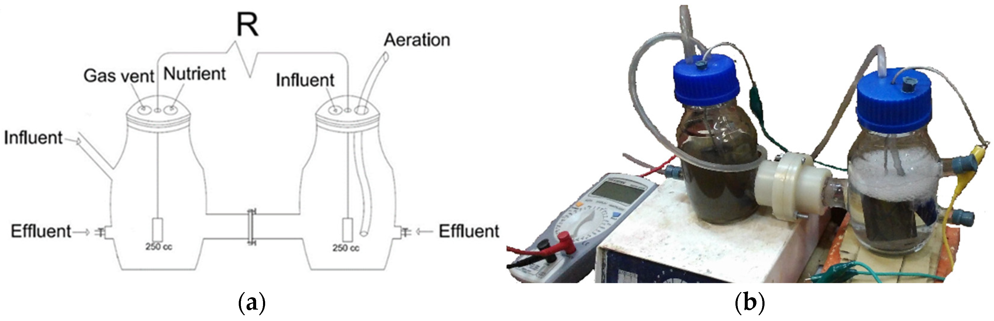
In this study, a dual-chamber MFC (Figure 1) with a 250 mL liquid volume (for each chamber) consisting of two glass chambers as anode and cathode chambers was used. The inlets and outlets of each chamber were used for clearing operations, sampling, discharging, and preparing for subsequent experiments. By perfectly isolating the chambers, the penetration of air and the departure of liquid were prevented. Transferring the proton condition from the anode to the cathode chamber was implemented by separating them with Nafion 117 as the Proton Exchange Membrane (PEM), which was 2 cm in diameter and produced in the United States. This membrane was allocated in a flench to be washable and reusable. The anode compartment was supplied with 20% (v/v) anaerobic sludge. All experiments were carried out at a temperature of 25 °C, and the solution remained at a constant pH of 7. Two graphite bars (G10) with a 36.5 cm2 surface area were utilized as anode and cathode electrodes, which were connected to the external resistance in the circuit through copper wire. An RH basic 2 IKA hotplate was used to gently mix the anolyte with a magnet. The MFC operated in the fed-batch mode. Each cycle was restarted when the voltage fell below 35 mV after approximately 48 h.
2.1.2. Chemicals and Apparatus
Commercial laccase was purchased from AB Enzymes GmbH Co., Darmstadt, Germany, and RB221 (Sumifix Blue 221) was obtained from Sumitomo Chemical Co. Ltd., Chuo City, Japan. Multiwalled CNTs were purchased from US Research Nanomaterials, Inc., Houston, TX, USA. N, N-Dimethylformamide (DMF), which was used to stabilize CNT debris on the cathode surface, silver sulfate, sulfuric acid, mercury sulfate, and potassium dichromate were purchased from Merck Co., Darmstadt, Germany. In this study, the measuring equipment was a blanketed potentiostat (model Bio-Logic SP300, Seyssinet-Pariset, France) for cyclic voltammetry (CV) measurements. The voltage was measured by a digital multimeter (GW Instek GDM-356). RB221 was analyzed by a UV-Vis spectrophotometer (Hach DR-4000) at a wavelength of 613 nm. A digital laboratory scale balance (model Mettler Toledo PJ300, Columbus, OH, USA) with an accuracy of 0.001 g was used to measure the masses of chemical substances. Furthermore, pH was regulated using 0.1 M H2SO4 (Merck) and 0.1 M NaOH (Merck) solutions using a pH meter (model AZ86502, Taichung City, Taiwan).
2.1.3. Feeding Microorganisms
Mixed culture microorganisms utilized for biofilm formation on the anode surface were obtained from anaerobic sludge from the Ekbatan wastewater treatment plant, which is situated in Tehran, Iran. The sludge was fed with synthetic wastewater including sucrose as a carbon source to reach 500 mg/L COD in 48 h cycles for about 50 days in the laboratory. For the sake of maintaining anaerobic conditions, gaseous nitrogen was sparged into the sludge volume to remove dissolved oxygen. Moreover, due to the continuous production of acid in the acidification phase of microbial community metabolism, the pH was constantly controlled to remain in the neutral range. Biofilm formation could be observed around the anode after only a few days of operating the system.
2.2. Experimental Phases
In this study, five phases were considered to evaluate the effects of different factors, such as CNT-modified/unmodified carbon graphite bar electrodes and different catholytes (including/excluding dye or laccase), on dye decolorization and power production efficiencies during experiments. These phases were as follows:
Phase A: Cathode chamber excluding dye and laccase, with an unmodified carbon graphite electrode;
Phase B: Cathode chamber excluding dye and laccase, with a CNT-modified carbon graphite electrode;
Phase C: Cathode chamber including dye and excluding laccase, with a CNT-modified carbon graphite electrode;
Phase D: Cathode chamber including laccase and excluding dye, with a CNT-modified carbon graphite electrode;
Phase E: Cathode chamber including dye and laccase, with a CNT-modified carbon graphite electrode.
2.2.1. Anolyte and Catholyte Composition
The anolyte was dissolved in 200 mL of nutrient medium containing 470 mg/L sucrose (as a carbon source), phosphate buffer (K2HPO4 and KH2PO4), and urea, which is important for anaerobic reactions. Trace factors added to the medium were as follows (per liter): 0.4 mg of FeCl3, 3 mg of MgSO4, 0.11 mg of CuSO4·5H2O, 0.7 mg of NaCl, 0.5 mg of ZnCl2, 4 mg of Na2S2O5, 0.254 mg of MnSO4·H2O, and 2.06 mg of FeSO4·7H2O. The catholyte contained a 0.1 M phosphate buffer (pH = 7) at some point in all experimental phases. The suitable quantity of suspended commercial laccase was determined to be 400 U/mL and 80 mg/L of RB221 was added to the buffer one at a time or collectively in a few phases.
2.2.2. Preparation of CNT Suspension and Cathode Coating
A casting method was used to cover the cathode with CNTs, for which 4 mg of CNTs was dispersed in 4 mL of DMF. The solution was sonicated for about 30 min, and the electrode surface was coated with 8 µL of the suspension after cleaning it with distilled water. Before the electrode was prepared for its installation in the system, it was baked at 150 °C for 1 h to diminish residual water [38] and placed in an ultrasonic bath to acquire a homogeneous suspension [39]. By using a micropipette, the electrode surface was coated with 8 µL of suspension after cleaning it with distilled water. Before the electrode was prepared to install in the system, it baked at 150 °C for 1 hour to diminish residual water [38].
2.2.3. Adsorption Test
For the adsorption experiment on graphite, 9 g of carbon graphite was finely crushed in order to decrease the effects of mass transfer resistance and was mixed with 0.5 L of the dye solution with a concentration of 80 mg/L in a closed Erlenmeyer flask to simulate the actual test conditions in the MFC [40]. A stirrer with a magnet was used to gently mix the suspension for 48 h (the time period of each test cycle). Then, a dye sample was extracted and centrifuged in order to remove the solid [41].
2.2.4. Calculations and Analysis
Through the spectrophotometric method, laccase enzyme activity was calculated at 25 °C using ABTS (2,2_azino-bis-[3-ethylbezothiazoline-6-sulfonic acid]). The reaction solution (3.2 mL) included 93.8 mM acetic acid (pH = 4.5), 0.5 mM ABTS, and 0.1 mL of laccase solution. The reaction started by adding ABTS solution (0.1 mM). The ABTS+ production rate was measured using a spectrophotometer at λ = 420 nm. A unit of enzyme activity (U) is equal to the amount of enzyme needed to oxidize 1 µL of ABTS per minute at 25 °C [42]. COD was periodically measured while adapting the microorganisms to the laboratory environment according to the standard method [43]. The decolorization efficiency was calculated (Equation (1)), where C0 is the initial concentration of the dye (mg/L), and C is the dye concentration (mg/L) at a given time [44].
Cyclic voltammetry (CV) is an electrochemical method used to elucidate the electrochemical behavior of a system and is commonly used to describe electron transfer interactions in the MFC anode chamber [45]. CV was used to evaluate the catalytic behavior of CNTs on the electrode surface, which was performed as a conventional three-electrode system to measure the oxygen reduction of CNTs. A Pt electrode was used as a counter electrode, an Ag/AgCl electrode was used as a reference electrode, and a CNT-coated electrode was used as the working electrode [46]. For the sake of obtaining polarization curves, the external resistance was changed from 1 Ω to 2 MΩ. The produced power was calculated as P and divided by the cathode surface area. In order to report the peak energy, the maximum point of the power density curve was considered. All experiments were performed at a constant temperature of 25 °C, and the optimal amounts were taken from three time–frequency tests of all experiments.
3. Results and Discussion
3.1. Cyclic Voltammetry
Cyclic Voltammetry (CV) was used to analyze the electrochemical characteristics of CNT-modified graphite electrodes. Figure 2 shows the CV response of the carbon graphite electrode in comparison with those of the CNT-modified carbon graphite electrode. Using CNTs as the electrode coating markedly increased the peak current of CV (curve b). It can be seen from the CNT-modified graphite curve (curve b) that the peak current is much higher and the horizontal interval between the anodic and cathodic peak potentials (∆Ep) is smaller than those of the carbon graphite curve (curve a). The results show the significance of CNT nanoparticles in improving the electroactive surface area. Therefore, CNT-modified carbon graphite electrodes appear to be more effective in dye decolorization compared to carbon graphite electrodes.
3.2. COD Variations of the Synthetic Substrate in the Anode Chamber
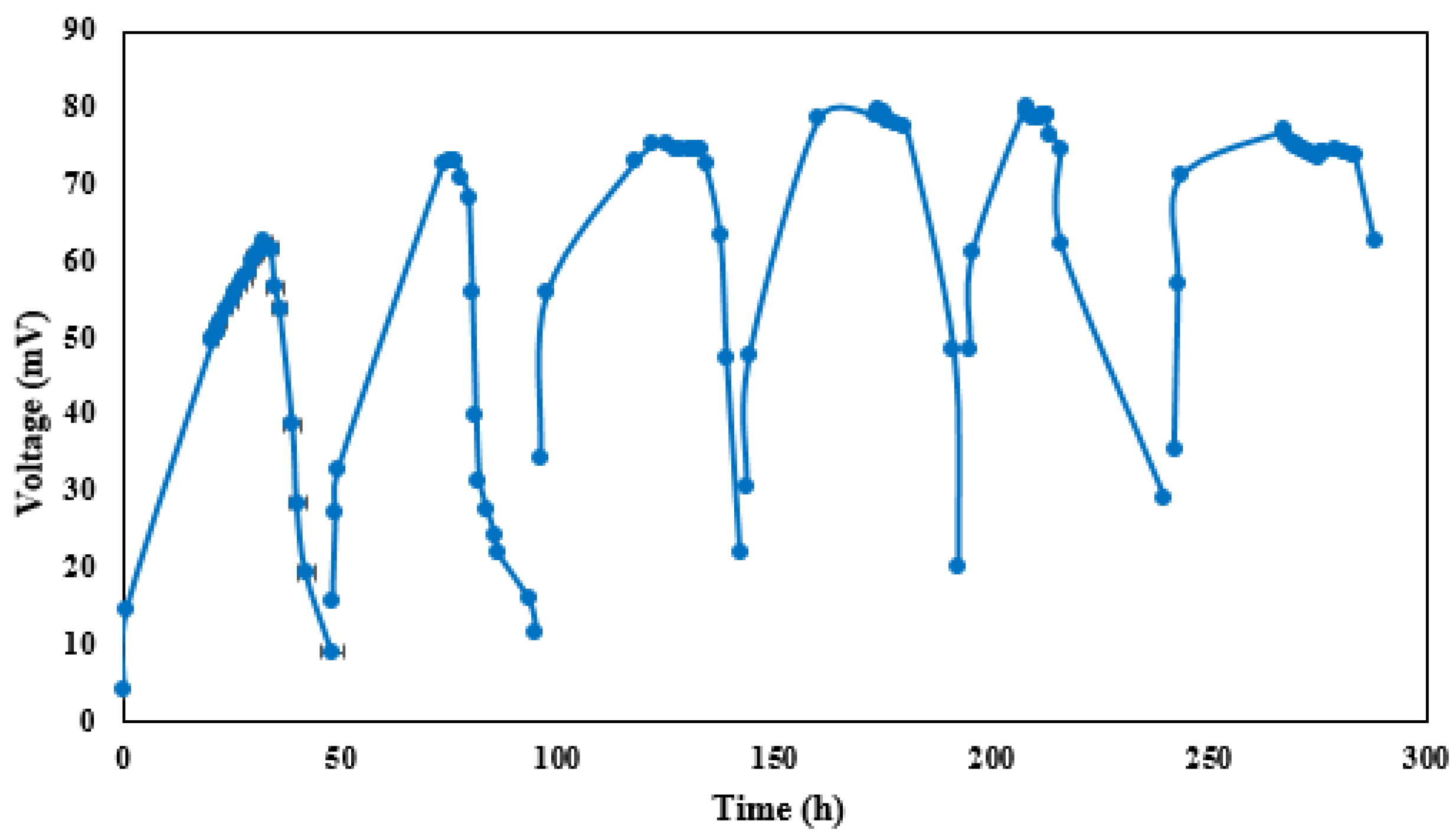
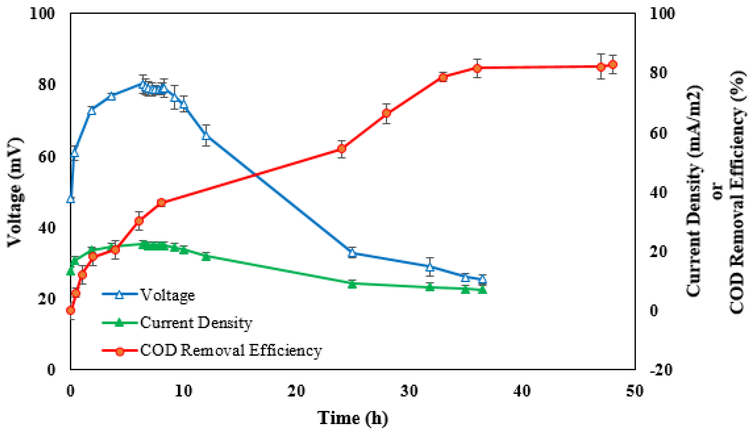
The time course of the voltage was recorded after synthetic wastewater was added to the anode compartment of the MFC including anaerobic sludge. Figure 3 shows the first six cycles of the tests with an unmodified carbon graphite bar used as the cathode electrode. During the first cycle, the open-circuit voltage increased to 64 mV during the start-up and remained unchanged for a few hours before gradually decreasing to a minimum value due to the lack of nutrients needed for microbial growth and metabolism. Furthermore, nearly constant maximum voltage values were observed from the fourth cycle to the fifth, which indicated the appropriate biofilm formation on the anode surface in order to start the tests [6]. Figure 4 shows the time course of the voltage and current density at an external resistance of 1 kΩ as well as the COD removal of the substrate during a fed-batch cycle. The results show a maximum voltage production of 80.3 mV only three hours after the initiation of the experiment; it lasted about eight hours due to the proportionality of the substrate consumption rate and voltage production and then revealed a sudden drop in voltage (to 22 mV), coinciding with an 82.3% COD removal efficiency (COD decreased to a value of 86.5 mg/L) at the end of the cycle (48 h). This was also observed by Kloch and Toczyłowska-Mamińska (2020) [47], where the highest COD removal (>94%) was achieved at an external resistance of 1 kΩ; however, this occurred over a longer period of time (after 20 days). The same pattern was investigated for current density variations during the cycle. Thirty-seven percent of the initial COD was removed during the first 11 h of the cycle, indicating that the maximum MFC performance occurred within the time between the beginning of the operation and the end of the system’s stable mode [47]. In contrast, at an external resistance of 300 Ω, ca. 95% COD was removed from brewery wastewater using a sequential anode–cathode MCF with only a 14 h hydraulic retention time [48].
3.3. Comparison of Phases
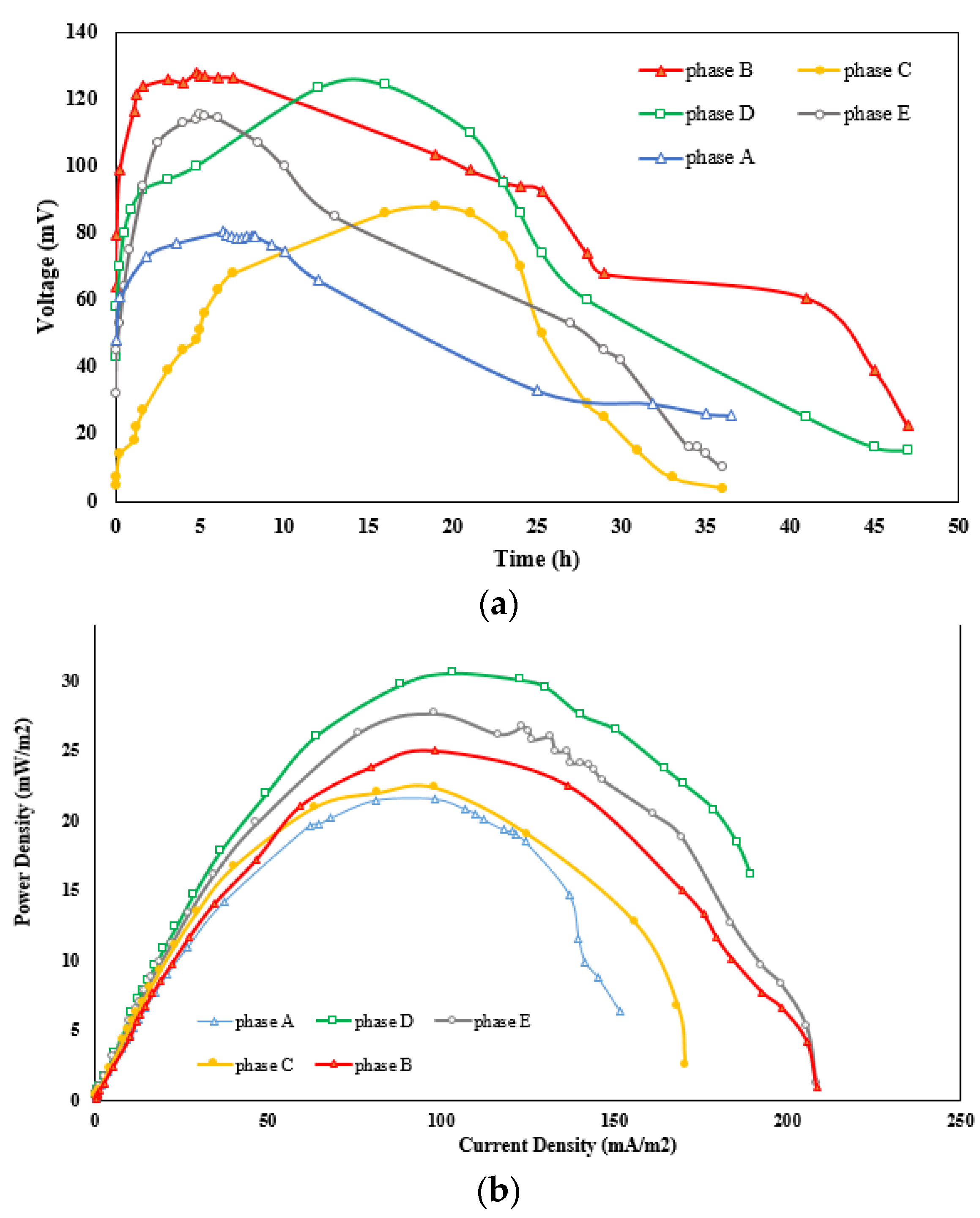
Maximum voltages of 80 and 120 mV and maximum power densities of 22 and 25 mW/m3 were observed during phases A and B (as shown in Figure 5), respectively, which could be due to the increased specific surface area of the cathode and greater access of the catholyte solution to reduce oxygen in water molecules. As a result, more transitions were transferred from the anode to the cathode compartment, while the produced voltage and power density increased. The maximum voltage and power density produced during phase B (128 mV and 25 mW/m3, respectively) decreased to 88 mV and 23.3 mW/m3, respectively, during phase C, which is irreconcilable with the other studies [49,50]. Bakhshian et al. [10] found that the power density obtained during phase B should be lower than the one produced during phase C. In the same vein, the remarkable differences in power density values between the current work and the literature may be because of the type of electrode used. For instance, CNTs and modified carbon graphite electrodes resulted in lower power generation when compared with the carbon brush electrode [49]. Furthermore, according to Savizi et al. [5], the maximum power density obtained in the presence of dye is lower than that observed in the absence of dye (using the carbon graphite bar as the cathode), which indicates that the RB221 dye decreased the MFC performance due to the electrode surface being covered with dye (surface adsorption), the oxidation of the dye, or the decomposition of intermediate compounds. Bakhshian et al. [10] studied RB221 byproducts and verified that a reduction in byproducts results in enhanced power production. In this study, the adsorption experiment showed a 14.3% reduction in dye concentration, which indicates that dye adsorption on the electrode surface could result in lower power production.
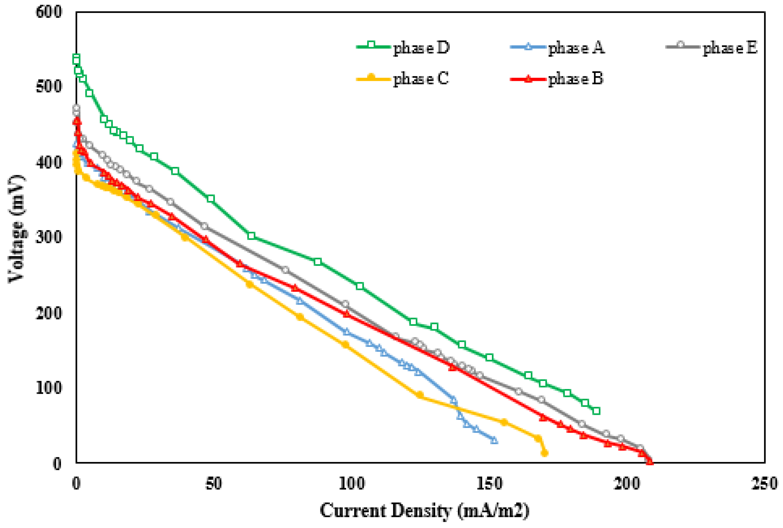
As shown in Figure 5a, the maximum voltage recorded during phase D (124.1 mV) was a bit lower than that obtained during phase B (128 mV). The slow enzyme activity in electron conveyance and its lower contact surface area compared to CNTs are possible reasons for this difference. Although the power density increased from 25 mW/m3 during phase B to 32 mW/m3 during phase D (Figure 5b), according to Savizi et al. [5], the laccase enzyme effectively reduces electron loss while transferring from the anode to the cathode compartment. The maximum voltage of 128 mV during phase B decreased to 115 mV during phase E. This decline could result from the adsorption of dye molecules on the cathode surface, as well as the low electron transfer activity and low contact surface area of the laccase enzyme. However, the maximum power density of 25 mW/m3 observed during phase B increased to a value of 27.6 mW/m3 during phase E, which is lower than that in a previous experiment [50]. The rise in the power density in phase E is due to the fact that the laccase enzyme is a catalyst for oxygen reduction and dye decolorization [10]. The polarization curves relate to all phases, as shown in Figure 6. It can be perceived that using CNTs as an electrode coating in the cathode chamber containing a buffer solution as a catholyte reduces the system’s internal resistance. In addition, the internal resistance of the MFC decreases more efficiently when utilizing a CNT-modified cathode in a buffer solution including the laccase enzyme.
3.4. Dye Removal
Free laccase was used to study the MFC performance in the enzymatic decolorization of RB221. A carbon graphite electrode modified with CNTs was used as the cathode chamber electrode. Initial concentrations of 30, 55, and 80 mg/L were determined in order to study enzymatic decolorization in the system’s cathode compartment. Synthetic wastewater with an initial COD of 500 mg/L was fed to the sludge in the anode chamber, and the dye and laccase were both dissolved in a buffer solution in the cathode compartment. The time course of the removal of the dye was recorded through three test cycles (each 48 h) at different initial dye concentrations, and then the mean results were recorded (Figure 7). After five hours, decolorization efficiencies of 23.3%, 27.3%, and 43.7% were observed for initial dye concentrations of 30, 55, and 80 mg/L. Maximum decolorization efficiencies of 58.7%, 69.4%, and 73.4% were also obtained after 15, 25, and 32 h when using initial dye concentrations of 30, 55, and 80 mg/L.
The results show that the maximum dye removal efficiency increases with higher initial dye concentrations. Conversely, Khan et al. [51] showed that the dye removal efficiency decreases with increasing dye concentration owing to enhanced biotoxicity and microbial activity and growth. In addition, by adding higher initial dye concentrations, not only did the maximum decolorization efficiency improve, but the initial (after five hours) decolorization efficiency also increased. Huang et al. [52] found that an MFC using a 2.5C humic acid-modified anode achieved an 83% decolorization efficiency of the azo dye Congo red in only 12 h, whilst, in another study [44], the decolorization time was very long (24 h), which eventually reached 80% Acid Orange 7 removal using an MFC with dye at the cathode in the presence of laccase.
4. Conclusions
When used as a cathode, the CNT-modified carbon graphite electrode shows higher MFC performance in terms of the maximum voltage production efficiency (50%) compared with an unmodified electrode. The maximum power density also increased from 22 mW/m3 (using the CNT-modified cathode) to 25 mW/m3 (using the unmodified cathode). The enzymatic decolorization of RB221 reduced both the maximum voltage and maximum power density. While removing the dye in the cathode chamber equipped with the CNT-modified electrode, the maximum power density and the voltage produced by the system decreased by about 7% and 31% compared to the same system with no decolorization in the cathode. However, a maximum decolorization efficiency of 73.4% and a COD removal of 82.3% were obtained in the anode and cathode chambers. The laccase enzyme added to the buffer solution in the cathode compartment equipped with the CNT-modified electrode caused a 28% increase in power density. Therefore, it can serve as a reliable material to produce a sufficient power density for dye decolorization.
Author Contributions
Conceptualization, M.A.M. and B.A.; Methodology, B.A.; Investigation, M.A.M. and B.A.; Resources, M.A.M. and S.H.; Supervision, B.A.; Writing—Original Draft, M.A.M.; Writing—Review and Editing, S.H. All authors have read and agreed to the published version of the manuscript.
Funding
This research received no external funding.
Institutional Review Board Statement
This study did not involve humans or animals.
Informed Consent Statement
This study did not involve humans.
Data Availability Statement
All data generated or analyzed during this study are included in this published article.
Acknowledgments
The authors would like to thank the Environmental Engineering Laboratory expert for laboratory support in this research.
Conflicts of Interest
The authors declare no conflict of interest.
References
- Panwar, N.; Kaushik, S.; Kothari, S. Role of renewable energy sources in environmental protection: A review. Renew. Sustain. Energy Rev. 2011, 15, 1513–1524. [Google Scholar] [CrossRef]
- Zhou, M.; Yang, J.; Wang, H.; Jin, T.; Hassett, D.J.; Gu, T. Bioelectrochemistry of microbial fuel cells and their potential applications in bioenergy. Bioenergy Res. Adv. Appl. 2014, 131–152. [Google Scholar] [CrossRef]
- Rozendal, R.A.; Hamelers, H.V.; Rabaey, K.; Keller, J.; Buisman, C.J. Towards practical implementation of bioelectrochemical wastewater treatment. Trends Biotechnol. 2008, 26, 450–459. [Google Scholar] [CrossRef] [PubMed]
- Choi, J.; Liu, Y. Power generation and oil sands process-affected water treatment in microbial fuel cells. Bioresour. Technol. 2014, 169, 581–587. [Google Scholar] [CrossRef] [PubMed]
- Savizi, I.S.P.; Kariminia, H.R.; Bakhshian, S. Simultaneous decolorization and bioelectricity generation in a dual chamber microbial fuel cell using electropolymerized-enzymatic cathode. Environ. Sci. Technol. 2012, 46, 6584–6593. [Google Scholar] [CrossRef]
- Liu, H.; Cheng, S.; Logan, B.E. Power generation in fed-batch microbial fuel cells as a function of ionic strength, temperature, and reactor configuration. Environ. Sci. Technol. 2005, 39, 5488–5493. [Google Scholar] [CrossRef]
- Sun, J.; Hu, Y.Y.; Bi, Z.; Cao, Y.Q. Simultaneous decolorization of azo dye and bioelectricity generation using a microfiltration membrane air-cathode single-chamber microbial fuel cell. Bioresour. Technol. 2009, 100, 3185–3192. [Google Scholar] [CrossRef]
- Song, Y.H.; An, B.M.; Shin, J.W.; Park, J.Y. Ethanolamine degradation and energy recovery using a single air-cathode microbial fuel cell with various separators. Int. Biodeterior. Biodegrad. 2015, 102, 392–397. [Google Scholar] [CrossRef]
- Mardanpour, M.M.; Esfahany, M.N.; Behzad, T.; Sedaqatvand, R. Single chamber microbial fuel cell with spiral anode for dairy wastewater treatment. Biosens. Bioelectron. 2012, 38, 264–269. [Google Scholar] [CrossRef]
- Bakhshian, S.; Kariminia, H.R.; Roshandel, R. Bioelectricity generation enhancement in a dual chamber microbial fuel cell under cathodic enzyme catalyzed dye decolorization. Bioresour. Technol. 2011, 102, 6761–6765. [Google Scholar] [CrossRef]
- Samanta, A.; Agarwal, P. Application of natural dyes on textiles. Indian J. Fibre Text. Res. 2009, 34, 384–399. [Google Scholar]
- Pereira, L.; Alves, M. Dyes—Environmental impact and remediation. In Environmental Protection Strategies for Sustainable Development; Springer: Dordrecht, The Netherlands, 2012; pp. 111–162. [Google Scholar]
- de Aragao Umbuzeiro, G.; Freeman, H.S.; Warren, S.H.; De Oliveira, D.P.; Terao, Y.; Watanabe, T.; Claxton, L.D. The contribution of azo dyes to the mutagenic activity of the Cristais River. Chemosphere 2005, 60, 55–64. [Google Scholar] [CrossRef]
- Katheresan, V.; Kansedo, J.; Lau, S.Y. Efficiency of various recent wastewater dye removal methods: A review. J. Environ. Chem. Eng. 2018, 6, 4676–4697. [Google Scholar] [CrossRef]
- Maleki, A.; Hamesadeghi, U.; Daraei, H.; Hayati, B.; Najafi, F.; McKay, G.; Rezaee, R. Amine functionalized multi-walled carbon nanotubes: Single and binary systems for high capacity dye removal. Chem. Eng. J. 2017, 313, 826–835. [Google Scholar] [CrossRef]
- Hooshmandfar, A.; Ayati, B.; Khodadadi Darban, A. Optimization of material and energy consumption for removal of Acid Red 14 by simultaneous electrocoagulation and electroflotation. Water Sci. Technol. 2016, 73, 192–202. [Google Scholar] [CrossRef]
- Caprarescu, S.; Miron, A.R.; Purcar, V.; Radu, A.L.; Sarbu, A.; Ion-Ebrasu, D.; Ghiurea, M. Efficient removal of Indigo Carmine dye by a separation process. Water Sci. Technol. 2016, 74, 2462–2473. [Google Scholar] [CrossRef]
- Aljuboury DA, D.A.; Palaniandy, P.; Abdul Aziz, H.B.; Feroz, S.; Abu Amr, S.S. Evaluating photo-degradation of COD and TOC in petroleum refinery wastewater by using TiO2/ZnO photo-catalyst. Water Sci. Technol. 2016, 74, 1312–1325. [Google Scholar] [CrossRef]
- de Farias Silva, C.E.; da Silva Gonçalves, A.H.; de Souza Abud, A.K. Treatment of textile industry effluents using orange waste: A proposal to reduce color and chemical oxygen demand. Water Sci. Technol. 2016, 74, 994–1004. [Google Scholar] [CrossRef]
- Abdelhamid, A.E.; El-Sayed, A.A.; Khalil, A.M. Polysulfone nanofiltration membranes enriched with functionalized graphene oxide for dye removal from wastewater. J. Polym. Eng. 2020, 40, 833–841. [Google Scholar] [CrossRef]
- Dotto, G.L.; McKay, G. Current scenario and challenges in adsorption for water treatment. J. Environ. Chem. Eng. 2020, 8, 103988. [Google Scholar] [CrossRef]
- Mousazadeh, M.; Niaragh, E.K.; Usman, M.; Khan, S.U.; Sandoval, M.A.; Al-Qodah, Z.; Emamjomeh, M.M. A critical review of state-of-the-art electrocoagulation technique applied to COD-rich industrial wastewaters. Environ. Sci. Pollut. Res. 2021, 28, 43143–43172. [Google Scholar] [CrossRef] [PubMed]
- Hassan, M.M.; Carr, C.M. A critical review on recent advancements of the removal of reactive dyes from dyehouse effluent by ion-exchange adsorbents. Chemosphere 2018, 209, 201–219. [Google Scholar] [CrossRef] [PubMed]
- Zulkefli, N.F.; Alias, N.H.; Jamaluddin, N.S.; Abdullah, N.; Abdul Manaf, S.F.; Othman, N.H.; Kusworo, T.D. Recent Mitigation Strategies on Membrane Fouling for Oily Wastewater Treatment. Membranes 2021, 12, 26. [Google Scholar] [CrossRef] [PubMed]
- Mehrizad, A.; Gharbani, P. Application of central composite design and artificial neural network in modeling of reactive blue 21 dye removal by photo-ozonation process. Water Sci. Technol. 2016, 74, 184–193. [Google Scholar] [CrossRef]
- Bilal, M.; Iqbal, M.; Hu, H.; Zhang, X. Mutagenicity, cytotoxicity and phytotoxicity evaluation of biodegraded textile effluent by fungal ligninolytic enzymes. Water Sci. Technol. 2016, 73, 2332–2344. [Google Scholar] [CrossRef]
- Naghipour, D.; Taghavi, K.; Moslemzadeh, M. Removal of methylene blue from aqueous solution by Artist’s Bracket fungi: Kinetic and equilibrium studies. Water Sci. Technol. 2016, 73, 2832–2840. [Google Scholar] [CrossRef]
- Upadhyay, P.; Shrivastava, R.; Agrawal, P.K. Bioprospecting and biotechnological applications of fungal laccase. 3 Biotech 2016, 6, 1–12. [Google Scholar] [CrossRef] [Green Version]
- Sonu, K.; Sogani, M.; Syed, Z.; Rajvanshi, J. Improved degradation of dye wastewater and enhanced power output in microbial fuel cells with chemically treated corncob anodes. Biomass Convers. Biorefinery 2022, 1–12. [Google Scholar] [CrossRef]
- Kim, J.R.; Kim, J.Y.; Han, S.B.; Park, K.W.; Saratale, G.D.; Oh, S.E. Application of Co-naphthalocyanine (CoNPc) as alternative cathode catalyst and support structure for microbial fuel cells. Bioresour. Technol. 2011, 102, 342–347. [Google Scholar] [CrossRef]
- Ter Heijne, A.; Strik, D.P.; Hamelers, H.V.; Buisman, C.J. Cathode potential and mass transfer determine performance of oxygen reducing biocathodes in microbial fuel cells. Environ. Sci. Technol. 2010, 44, 7151–7156. [Google Scholar] [CrossRef]
- Taskan, E.; Ozkaya, B.; Hasar, H. Combination of a novel electrode material and artificial mediators to enhance power generation in an MFC. Water Sci. Technol. 2015, 71, 320–328. [Google Scholar] [CrossRef]
- Wu, H.; Lu, M.; Guo, L.; Bay, L.G.H.; Zhang, Z.; Li, S.F.Y. Polyelectrolyte–single wall carbon nanotube composite as an effective cathode catalyst for air-cathode microbial fuel cells. Water Sci. Technol. 2014, 70, 1610–1616. [Google Scholar] [CrossRef]
- Ghasemi, M.; Ismail, M.; Kamarudin, S.K.; Saeedfar, K.; Daud WR, W.; Hassan, S.H.; Oh, S.E. Carbon nanotube as an alternative cathode support and catalyst for microbial fuel cells. Appl. Energy 2013, 102, 1050–1056. [Google Scholar] [CrossRef]
- Ghasemi, M.; Sedighi, M.; Tan, Y.H. Carbon Nanotube/Pt Cathode Nanocomposite Electrode in Microbial Fuel Cells for Wastewater Treatment and Bioenergy Production. Sustainability 2021, 13, 8057. [Google Scholar] [CrossRef]
- Mikhaylova, A.A.; Tusseeva, E.K.; Mayorova, N.A.; Rychagov, A.Y.; Volfkovich, Y.M.; Krestinin, A.V.; Khazova, O.A. Single-walled carbon nanotubes and their composites with polyaniline. Structure, catalytic and capacitive properties as applied to fuel cells and supercapacitors. Electrochim. Acta 2011, 56, 3656–3665. [Google Scholar] [CrossRef]
- Zhu, H.Y.; Jiang, R.; Huang, S.H.; Yao, J.; Fu, F.Q.; Li, J.B. Novel magnetic NiFe2O4/multi-walled carbon nanotubes hybrids: Facile synthesis, characterization, and application to the treatment of dyeing wastewater. Ceram. Int. 2015, 41, 11625–11631. [Google Scholar] [CrossRef]
- Tsai, H.Y.; Wu, C.C.; Lee, C.Y.; Shih, E.P. Microbial fuel cell performance of multiwall carbon nanotubes on carbon cloth as electrodes. J. Power Sources 2009, 194, 199–205. [Google Scholar] [CrossRef]
- Jain, R.; Sharma, S. Glassy carbon electrode modified with multi-walled carbon nanotubes sensor for the quantification of antihistamine drug pheniramine in solubilized systems. J. Pharm. Anal. 2012, 2, 56–61. [Google Scholar] [CrossRef] [Green Version]
- Pereira MF, R.; Soares, S.F.; Órfão, J.J.; Figueiredo, J.L. Adsorption of dyes on activated carbons: Influence of surface chemical groups. Carbon 2003, 41, 811–821. [Google Scholar] [CrossRef]
- Bradder, P.; Ling, S.K.; Wang, S.; Liu, S. Dye adsorption on layered graphite oxide. J. Chem. Eng. Data 2011, 56, 138–141. [Google Scholar] [CrossRef]
- Yang, X.Q.; Zhao, X.X.; Liu, C.Y.; Zheng, Y.; Qian, S.J. Decolorization of azo, triphenylmethane and anthraquinone dyes by a newly isolated Trametes sp. SQ01 and its laccase. Process Biochem. 2009, 44, 1185–1189. [Google Scholar] [CrossRef]
- American Public Health Association, & American Water Works Association. Standard methods for the examination of water and wastewater. In Standard Methods for the Examination of Water And Wastewater; American Public Health Association: Washington, DC, USA, 1995; p. 1000. [Google Scholar]
- Mani, P.; Fidal, V.T.; Bowman, K.; Breheny, M.; Chandra, T.S.; Keshavarz, T.; Kyazze, G. Degradation of azo dye (acid orange 7) in a Microbial fuel cell: Comparison between anodic microbial-mediated reduction and cathodic laccase-mediated oxidation. Front. Energy Res. 2019, 7, 101. [Google Scholar] [CrossRef]
- López Zavala, M.Á.; González Peña, O.I.; Cabral Ruelas, H.; Delgado Mena, C.; Guizani, M. Use of cyclic voltammetry to describe the electrochemical behavior of a dual-chamber microbial fuel cell. Energies 2019, 12, 3532. [Google Scholar] [CrossRef] [Green Version]
- Deng, L.; Zhou, M.; Liu, C.; Liu, L.; Liu, C.; Dong, S. Development of high performance of Co/Fe/N/CNT nanocatalyst for oxygen reduction in microbial fuel cells. Talanta 2010, 81, 444–448. [Google Scholar] [CrossRef] [PubMed]
- Kloch, M.; Toczyłowska-Mamińska, R. Toward optimization of wood industry wastewater treatment in microbial fuel cells—Mixed wastewaters approach. Energies 2020, 13, 263. [Google Scholar] [CrossRef] [Green Version]
- Wen, Q.; Wu, Y.; Zhao, L.X.; Sun, Q.; Kong, F.Y. Electricity generation and brewery wastewater treatment from sequential anode-cathode microbial fuel cell. J. Zhejiang Univ. Sci. B 2010, 11, 87–93. [Google Scholar] [CrossRef] [Green Version]
- Karuppiah, T.; Pugazhendi, A.; Subramanian, S.; Jamal, M.T.; Jeyakumar, R.B. Deriving electricity from dye processing wastewater using single chamber microbial fuel cell with carbon brush anode and platinum nano coated air cathode. 3 Biotech 2018, 8, 1–9. [Google Scholar] [CrossRef]
- Yang, H.; Chen, J.; Li, W.; Li, Y.; Huang, X.; Zhou, L.; Zhu, S. Performance of Constructed Wetland-Microbial Fuel Cell for Promoting Nutrient Removal and Electricity Generation. In Journal of Physics: Conference Series; IOP Publishing: Bristol, UK, 2021; Volume 2044, No. 1; p. 012029. [Google Scholar]
- Khan, N.; Anwer, A.H.; Ahmad, A.; Sabir, S.; Sevda, S.; Khan, M.Z. Investigation of CNT/PPy-modified carbon paper electrodes under anaerobic and aerobic conditions for phenol bioremediation in microbial fuel cells. ACS Omega 2019, 5, 471–480. [Google Scholar] [CrossRef] [Green Version]
- Huang, W.; Chen, J.; Hu, Y.; Chen, J.; Sun, J.; Zhang, L. Enhanced simultaneous decolorization of azo dye and electricity generation in microbial fuel cell (MFC) with redox mediator modified anode. Int. J. Hydrogen Energy 2017, 42, 2349–2359. [Google Scholar] [CrossRef]
Figure 1.
(a) Schematic and (b) original apparatus of the MFC constructed.

Figure 2.
CV of the cathode (a) before and (b) after modification with CNTs.

Figure 3.
Time course of voltage during the first six cycles of MFC operation.

Figure 4.
COD removal efficiency, voltage, and current density during a fed-batch cycle (external resistance = 1 kΩ).
Figure 4.
COD removal efficiency, voltage, and current density during a fed-batch cycle (external resistance = 1 kΩ).

Figure 5.
Comparison of different phases: (a) interaction between voltage and time; (b) interaction between power density and current density.
Figure 5.
Comparison of different phases: (a) interaction between voltage and time; (b) interaction between power density and current density.

Figure 6.
Polarization curves of all phases.

Figure 7.
Time course for decolorization of RB221 at different dye concentrations by CNT-modified cathode and free laccase in cathode compartment of MFC.
Figure 7.
Time course for decolorization of RB221 at different dye concentrations by CNT-modified cathode and free laccase in cathode compartment of MFC.

Disclaimer/Publisher’s Note: The statements, opinions and data contained in all publications are solely those of the individual author(s) and contributor(s) and not of MDPI and/or the editor(s). MDPI and/or the editor(s) disclaim responsibility for any injury to people or property resulting from any ideas, methods, instructions or products referred to in the content. |
© 2022 by the authors. Licensee MDPI, Basel, Switzerland. This article is an open access article distributed under the terms and conditions of the Creative Commons Attribution (CC BY) license (https://creativecommons.org/licenses/by/4.0/).
Share and Cite
MDPI and ACS Style
Mousavian, M.A.; Hosseini, S.; Ayati, B. Bioelectricity Generation and Decolorization of Reactive Blue 221 Using a Modified Cathode Dual-Chamber Microbial Fuel Cell. Water 2023, 15, 101. https://doi.org/10.3390/w15010101
AMA Style
Mousavian MA, Hosseini S, Ayati B. Bioelectricity Generation and Decolorization of Reactive Blue 221 Using a Modified Cathode Dual-Chamber Microbial Fuel Cell. Water. 2023; 15(1):101. https://doi.org/10.3390/w15010101
Chicago/Turabian StyleMousavian, Mohammad Amin, Sepideh Hosseini, and Bita Ayati. 2023. "Bioelectricity Generation and Decolorization of Reactive Blue 221 Using a Modified Cathode Dual-Chamber Microbial Fuel Cell" Water 15, no. 1: 101. https://doi.org/10.3390/w15010101
Note that from the first issue of 2016, this journal uses article numbers instead of page numbers. See further details here.