

Evaluating the Feasibility of Robotic Crawler Deployed Ground Penetrating Radar to Assess Repairs of a Concrete Hydroelectric Dam Spillway in Alabama, USA

Bigman Geophysical LLC, Norcross, GA 30093, USA
Water 2023, 15(10), 1858; https://doi.org/10.3390/w15101858
Submission received: 24 March 2023
/
Revised: 11 May 2023
/
Accepted: 12 May 2023
/
Published: 14 May 2023
(This article belongs to the Special Issue Dam Safety. Protection against Overtopping and Prevention of Geo-Structural Failure)
Abstract
:Dams and the water systems they support must be monitored, maintained, and repaired when necessary so they can continue to provide benefits to the communities they serve. This study presents the methods and results from a robotic crawler-based ground penetrating radar (GPR) inspection of rehabilitated concrete from a hydroelectric dam spillway located in Alabama, USA. This spillway, which was recently inspected and repaired, showed evidence of spalling which indicated internal structural deterioration. Standard practice would leave these repairs uninspected or put the wellbeing of people at risk when deploying them on the spillway for manual inspections. GPR data were recorded from recently rehabilitated and resurfaced areas of the site to evaluate the capability of a remotely controlled robotic crawler system to assure repair quality efficiently and effectively. The results indicate that high quality data can be recorded from repairs without the need for manual inspection. The GPR was able to resolve repair length, thickness, number of reinforcements, reinforcement spacing, and cover depth. The study encountered several difficulties, and the author proposes future pathways of development for safely inspecting critical dam infrastructure with steep slopes and slippery, rough surfaces.
1. Introduction
Dams are a critical feature in many water management systems, but the aging process has put the structural integrity of many dams at risk. Dams made of concrete are particularly troubled since weathering can cause erosion of the surface; constant exposure to moisture may cause corrosion and expansion of reinforcements which may crack the concrete; alkali–silica reaction, fire exposure, or freezing–thawing processes may cause spalling. All of these can have deleterious effects on dam spillways such as reduced strength, shortened use life, or even failure.
The current conditions of dams in the United States, for example, are troubling; 2300 of the 15,600 dams classified as high-hazard structures are deficient [1]. The average age of dams in the United States is 57 years, and it is estimated that 70% of dams will be over 50 years of age by 2030 [1]. While age is not necessarily an inditement on condition, it is likely that many of these are not built to modern construction standards. This is evident in some of the recent dam failures in California and Michigan. Funding for the inspection and repair of dams has also increased in recent years. The Twenty-First Century Dams Act was approved in July of 2021 by the United States Congress “to provide funding to rehabilitate, retrofit, and remove the Nation’s dams to improve the health of the Nation’s rivers, improve public safety, and increase clean energy production.” The funding outlined in the Act specifically is allocated for rehabilitation, dam safety, inspection, staffing, etc. Despite this increased interest and re-allocation of funds, it remains important to develop safe, low-cost methods for inspecting concrete dams and assuring the quality of rehabilitation.
A growing recognition of the scale of this problem across the world has prompted research into non-destructive testing (NDT) of concrete for defect characterization [2,3], condition and leakage assessments [4,5,6,7,8], and failure prediction models of both embankment and concrete dams [9,10]. Ground penetrating radar (GPR) has been one of the most widely studied techniques for structural assessments. The application of GPR to detect structural elements [11] and defects [12] in concrete is now well documented. Researchers have conducted field tests over the past decade to evaluate the effectiveness of GPR for characterizing concrete dams [2,3,4,5,6,7,8,13], pavements [14,15], bridge decks [16,17], and other specialty infrastructure [13,18,19]. This helped to mature our understanding of the problem and refine our testing methods and protocols for these applications.
The development of NDT for concrete has been significant along three pathways. First, our understanding of defect localization and characterization has grown [12,18,20,21,22]. Methods for identifying cracks, delamination, honeycombing, and voiding in concrete structures are well understood. Depth, breadth, and orientation of delamination and other defects can be measured with high-frequency GPR [2]. Comprehensive data processing methods now assist in modelling and measurement of such targets [22,23], including automatic detection of signal phase and reflection geometry [22].
Second, many studies have been completed to help evaluate moisture, chloride gradients, and corrosion of steel members [24,25,26]. These studies have found relationships between corrosive effects and both GPR signal amplitude and attenuation rates. Lower wave amplitudes resulted from reduced reinforcement surface area because of oxidation and attenuation rates increased based on moisture and chloride content. Full-waveform inversion and numerical analysis have been particularly useful in reconstructing condition maps.
Finally, much research has been conducted on dam leakage. While electrical resistivity tomography (ERT) has been a popular tool for earthen dams [27,28], GPR has been critical to investigating leakage of concrete dam faces [5,7,8]. Research has found that leakage zones may cause amplitude reductions near the surface due to increased moisture content [5], but also may reveal pathways of leakage from high amplitude reflection events where the leakage zone contrasts with the surrounding fill [5,7]. Other researchers have identified frequency downshift as a possible indicator for leakage since the highest frequencies of the broadband GPR antenna will be absorbed first in locations with more moisture [8]. Leakage studies are important because they can also reveal locations of probable voiding from erosion processes.
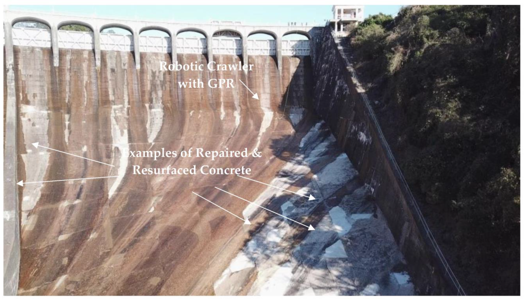
While the application of GPR to evaluate defects, conditions, and leakage have been the subject of many studies, no investigations are published on the possibility of quality assurance following the refurbishment of concrete with these problems. This development would be significant to apply to all concrete structures, but dams on steep slopes present unique safety concerns and data acquisition problems for such investigations. The purpose of this study is to evaluate the effectiveness of an unmanned robotic crawler integrated with a GPR sensor for inspecting the refinished concrete surface of a particularly problematic hydroelectric dam spillway (Figure 1). Specifically, this study tested system durability, data acquisition speed, sources of noise, and data quality for the purposes of quality assurance of refinished concrete at the site. Research into the development of autonomous and robotic deployment methods for GPR has been forthcoming [29,30,31,32,33,34], but much of this work has been focused on flat surface acquisition and none for steep dam slopes. Thus, an inductive approach was taken for this study by developing an integrated system (crawler and GPR) based on expected site conditions and the data required to effectively evaluate the repaired and refinished surfaces. The outcomes of this study identify successes and failures with this specific deployment method and will assist other researchers working on similar problems or those building similar solutions to speed up pathways toward large-scale inspection of deteriorating infrastructure. The results of this study will facilitate progress on future developments in inspection technology addressing specialty infrastructure consisting of large areas, steep slopes, rough surfaces, and/or active water flow across surfaces.
The dam under investigation is in Alabama, USA and was built to provide water supply, flood control, and hydroelectric power (its associated power plant generates over 327 million KWh per year). Construction began in 1923 and was completed in 1926. The dam is 51 m high, 610 m long, is controlled by 20 gates, and has a discharge capacity of 3800 m3/s. The associated lake covers an area of roughly 16,000 ha and stretches 49 km upstream. This dam is a critical piece of infrastructure for its hydrological, energy, and economic importance.
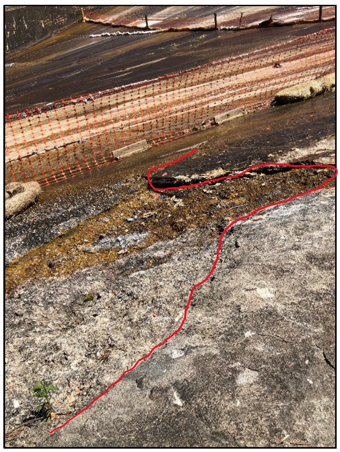
The dam currently suffers from erosion, delamination, and surface spalling (Figure 2), and was selected as the test site due to concern over structural integrity. Since a refurbishment plan was put in place for this asset, it was deemed an appropriate and timely site to conduct this investigation. A program was previously undertaken to inspect the entirety of the accessible dam spillway and rehabilitate spalled areas [2]. Since this dam was not subject to fire and is not reinforced, spalling is most likely due to freezing/thawing episodes and alkali–silica reactions typical of cement used in construction during the 1920s. The long life this dam has enjoyed also contributed to the current state of deteriorated surface condition. Areas with observable spalling were filled, reinforced, and resurfaced. Inspections also uncovered areas indicative of delamination in the concrete which were subsequently demolished to solid concrete, reinforced, filled, and resurfaced.
2. Materials and Methods
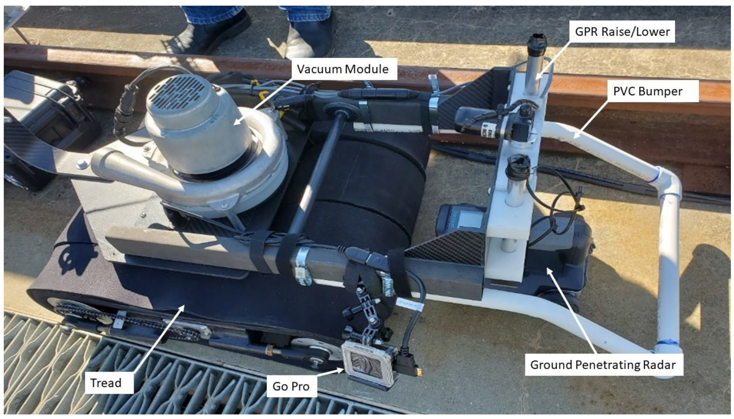
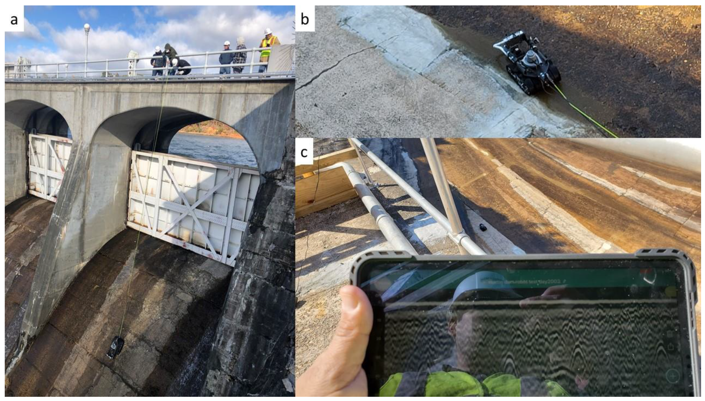
This project tested the design and applicability of a remotely controlled robotic crawler to access the spillway and image repaired and resurfaced concrete that suffered from spalling and delamination (Figure 2). While the project considered the use of other robotic options, such as UAV, the concrete condition, and steep slope of the spillway were not amenable to the use of UAV at this time. Over a two-day period, the design and mobility of the crawler itself were tested as well as the ability to remotely collect GPR data. The crawler (Figure 3), designed by ICM (Ithica, NY, USA), uses a vacuum motor and neoprene treads to adhere to and travel on vertical or near vertical surfaces. An attachment was constructed to hold and maneuver the GPR system on the crawler. A mechanism was added to raise and lower the GPR to the surface while on the spillway. This provided the ability to raise the GPR off the ground while preparing to acquire data and then lower the GPR back onto the surface during data acquisition. A GoPro was attached to the crawler to visualize the GPR’s mechanical performance in real time. The crawler with attached GPR was lowered with ropes from the top of the dam to the spillway below (Figure 4a). The crawler was then operated remotely through cables running from the crawler to a console. The crawler with GPR was tested by collecting data specifically over patched concrete that was recently refinished (Figure 4b). GPR data acquisition was operated wirelessly from the deck of the dam with an iPad (Figure 4c).
GPR is widely applied to solve archaeological [35,36], forensic [37,38], environmental [39], engineering [40], and agricultural [41] problems. GPR generates electromagnetic radio waves from an antenna that is pushed or pulled along the ground surface and records backscattered echoes from reflections off material changes in the subsurface [42]. These antennas are typically considered ground coupled so much of the energy propagates through the subsurface and only limited amounts of energy travel above the ground through the air. The amount of energy reflected at a subsurface discontinuity is primarily dependent on the degree of contrast in dielectric permittivity values of the two materials [43,44]. Larger differences in dielectric permittivity result in recorded echoes of higher amplitude, while less contrast results in subtler responses. Antenna frequencies influence the depth of penetration and resolution where higher frequencies may record reflections from smaller objects but will only prospect to shallow depths, and lower frequencies will penetrate deeper into the subsurface but may only record reflection events from larger objects or layers [43,44]. Typical frequencies for concrete inspection range from 1 to 3 GHz. Object or layer size, shape, and orientation will influence the reflection geometry recorded by the GPR. A GPR system can record data in 1, 2, or 3-dimensions depending on the deployment method. This study focused on 2D data acquisition and presentation to assess selected concrete repairs, which would facilitate the comparisons with prescribed repair specifications (see Section 4).
A Proceq GP8000 stepped frequency continuous wave (SFCW) GPR manufactured by Screening Eagle Technologies (Schwerzenbach, Switzerland) was selected for data acquisition. This SFCW sensor produces a broad range of frequencies from approximately 0.2 GHz to 4.0 GHz. Many have documented the benefits of producing this wide range with a “single tone” and then transforming the reflected wave from the frequency domain to the time domain [45,46,47,48,49,50]. For example, resolution and depth tend to improve, there is generally a high signal-to-noise ratio, and SFCW GPR typically requires lower power outputs. One potential drawback of SFCW GPR is the possibility of direct wave signal saturation due to transmitter/receiver coupling [45]. This phenomenon may impede the receiver from recording reflection events from weak return signals generated at depth. A second potential drawback is the need for a longer signal duration [47]. This is required to step up frequencies during wave generation and may slow down data acquisition rates. Since the resurfaced targets were shallow (often in the first few centimeters) and the crawler velocity was slow, it was concluded that the potential benefits outweighed the drawbacks which would only have a negligible impact on investigation outcomes.
The GPR collected data at a step rate of 1 scan/cm and a total time window of 16 ns. Both linear gains and time gains were applied in the field to maximize the likelihood of identifying possible targets of interest. In general, the linear gain was set to 25 dB and the time gain was set to 4.9 dB/ns. A hyperbola fit was applied to estimate dielectric permittivity and ultimately thickness of repair and reinforcement cover depth. The concrete had an average dielectric permittivity of approximately 9.5 and, thus, an average wave velocity of approximately 0.097 m/ns during the investigation.
3. Results
Site conditions were windy during the first day of trials. When lowering the crawler to the spillway, its position was unstable, and the system rotated during descent. Once in the appropriate orientation, the crawler was lowered completely onto the spillway surface. It became evident that the impact of lowering the crawler to the concrete slab created stress on the arm holding the GPR and possibly on the GPR itself. Once flushed with the surface of the concrete, the crawler’s vacuum motor was switched on and the crawler’s maneuverability was tested. The crawler generally operated well, but on a few very rough surfaces, the vacuum lost its seal. The fixed position of the wheels and GPR made turning difficult. Some modifications were required before data could adequately be acquired with the GPR. For example, the GPR struggled to collect data when positioned in the front of the crawler and pushed on the ground surface since the sensor would get caught on large pieces of aggregate or cracks in the concrete. The odometer embedded in the GPR wheels is required to rotate for the GPR to generate a signal and record subsurface responses. When pushing the GPR over rough terrain, the wheels often did not consistently maintain contact and rotate. Continuous data profiles were unable to be recorded during day 1 of trials.
Many of the issues encountered during the first day of testing were resolved prior to the second day of testing. An extended arm boom with a pulley facilitated an easier and more stable lowering of the crawler from the top of the dam (Figure 5). This consisted of an extension approximately 1 m in length from the side of the spillway lip which provided much more control in lowering the crawler down to the spillway. A PVC bumper (see Figure 3) was added to reduce impact stress on the GPR and the crawler’s arm. Data collection was greatly improved by positioning the GPR in the rear of the crawler and dragging the sensor rather than pushing it. Wheel contact remained more consistent which allowed for continuous data acquisition and clear results (Figure 6). Streaming video of the GPR in real time with the GoPro was instrumental in identifying wheel skips, contact issues and quickly troubleshooting them. While communication was good overall between the GPR and the tablet, some problems arose when the distance exceeded approximately 100 m. At these distances (sometimes shorter) the wireless connection dropped, and the data ceased to be logged. The crawler had to be driven closer to the tablet to regain connection. This may be fixable with a wireless amplifier to extend the distance of communication between the data logger and GPR. Some noise was present in the GPR data profiles collected with the crawler (Figure 6), but it remains unclear if the source of the noise was the crawler itself or some other external factor.
The GPR recorded clear, high-resolution data of the refinished areas on the spillway (Figure 7). Data were of sufficient quality to measure the approximate width and thickness of repair, count the number of hyperbolic reflection responses indicative of steel reinforcements, and evaluate the consistency of reinforcement spacing and depth. Measurements indicate the width of the repair under investigation was approximately 130 cm. The bottom of the repair is indicated by a horizontal reflection event. Using this response, the repair can be measured at 12 cm thick (Figure 7). Seven hyperbolic reflections were recorded with the GPR. These were spaced approximately 15 cm (6 inches) apart with minimal variation. The depths of reflections from reinforcements varied by less than 3 cm with the range of depths between roughly 2 cm and 4 cm deep (Figure 7).
4. Discussion
Most problems that arose during crawler deployment were minor and easily mitigated within the two days onsite. Two benefits were confirmed from the robotic deployment. First, it allowed for previously inaccessible portions of the dam to be scanned with GPR. Second, the spillway could also be accessed remotely, keeping technicians safely on the platform of the dam. The spillway was steep, slippery, and dangerous to work on. The previous inspection of the dam which located delamination was conducted manually. The infrastructure needed for the manual collection of GPR data on the spillway was much greater in terms of both time and money than the deployment of the robotic crawler. The approximate time required to construct scaffolding to access the spillway took four days with another two days to break down. Procuring adequate scaffolding was expensive in addition to expenses for crew and crane rental. Robotic data collection was much more streamlined and cost effective as it required no scaffolding for access.
The data collected with the GPR was able to verify that specifications were met for repairs of the concrete surface. According to the scope, saw cuts shall be perpendicular to the concrete surface or tilted inwards between 5 and 10 degrees, and 15 cm × 15 cm wire mesh will be added to the pour area for crack control (size W9 × W9 mesh for pours deeper than 10 cm and W6 × W6 size for pours 10 cm or less). The GPR data indicate a roughly perpendicular shape to the sides of the repair as evidenced by the horizontal reflection event approximately 12 cm below the surface (Figure 7). The reflection trend does not indicate a descending/ascending bottom of repair, suggesting a “pit shape” but rather a squared angle cut both upslope and downslope of the repair. The GPR recorded hyperbolic reflection responses consistent with 15 cm × 15 cm wire mesh as specified for the repair. The depth of concrete was 12 cm and thus the size of the wire mesh should be W9 × W9; however, the data collected in this circumstance were not conducive to making such an estimate. This would be an important upgrade for future research.
There were several limitations to this study as well. First, the investigation was conducted over a two-day period. While we were able to troubleshoot many of the deployment problems encountered over the two days it still only was enough time to collect a limited amount of data. Additional days on site would provide a better understanding of the mechanical limitations of the crawler and would allow for more modifications. Second, the system was only able to test a limited number of repaired and refurbished locations, and only in 2D. The study produced no 3D visualizations of refurbished concrete; thus, no volumetric measurements could be calculated with the current data. Third, the collected data was of high quality but may not be representative of data collected on other structures manufactured with different concrete materials or other project sites presenting different conditions. Future deployments at other dams would help validate the quality of results collected at the current site and provide comparisons for wider applications. Fourth, only one GPR sensor was tested at this site. Although this sensor produces a wide range of frequencies, additional testing with a different GPR would provide a basis for comparison. Varying the number of wheels would help test maneuverability, varying wave generation methods (SFCW vs. pulsed) would help test acquisition speed, and varying frequencies would verify which parts of the spectrum are most applicable. Low frequencies could provide a benefit in situations where refurbishment was thick while ultra-high frequencies might provide more detail on surficial repairs. Finally, data acquisition was much slower with the crawler than with operating the GPR manually with a human technician. Velocity limitations will have to be overcome to apply this technique on a large scale.
Based on our initial findings, there appear to be many pathways of worthwhile future research. First, there is unwanted noise in the data. While this might be removed using frequency or background filters during post-processing, it is important to know what the source of the noise is. It is likely to be the crawler itself, but this should be tested. Data acquired during the manual inspection of the dam did not contain the same category of noise and suggests influence from the robot. If the components of the crawler that are producing noise can be isolated, then dampeners, or frequency cancelling mechanisms can be applied to minimize or reduce noise. The effects of noise did not compromise the current study because the targets were shallow, but thicker refurbishments might be impacted by such noise.
Second, the crawler permits safe data acquisition, but speed was a problem. Across the two days, only a few refinished areas were tested. While quality assurance testing can be performed in a short period of time, there should be a move towards large area data collection for the inspection phase. This would prevent the need to include human technicians on the surface and improve project safety. One of the problems with data collection speed stemmed from GPR odometer contact with the rough surface. Odometer skipping causes breaks in the data and can influence data continuity and measurement accuracy (an example can be seen in the third hyperbola from the left in Figure 7). Redesigned GPR wheels that account for rugged terrain might mitigate against this problem and encourage enhanced data acquisition speeds. An alternative to this would be to reduce the number of wheels down from 4 to 2, which may improve maneuverability and help maintain contact, especially if both wheels have an odometer. A benefit of continued contact is a consistent data stream.
Third, positioning mechanisms need to be developed for accurate georeferencing of data and smoother workflow. GPS seemed to be an inappropriate method on such a steep slope. If a GPS is to be deployed, it should have tilt compensation for accurate positioning in three-dimensional space while the crawler is moving up a steep slope or vertical face. A robotic total station may be a better approach to tracking and following the GPR, but novel positioning systems should be considered. One issue that a robotic total station might have is with datum setup. The total station needs to be placed in a location of the spillway that can also detect the GPR throughout its data capture. If the total station needs to be placed on the spillway itself, then this defeats the purpose of an unmanned data collection system. Accelerometers should be explored to assist in compensating for the tilt of the radar antenna. This will be critical for accurate subsurface positioning during data processing, transformation, and creation of 3D models.
Fourth, additional relevant measurements should be calculated once data collection speeds increase. For example, full coverage of rehabilitated areas would allow for results on concrete volume. It has been shown that full coverage of sites or features with GPR can provide a basis for more complex visualizations, higher-order statistical analysis, and more diversified interpretations [51]. This will help answer additional questions that cannot be approached with two-dimensional data.
Fifth, additional sensors should be considered for both inspection and quality assurance programs. Some potential sensors to consider include ultrasonic pulse echo, eddy current (cover meters), and half-cell potential to locate defects, characterize conditions, or image refurbishments. Ultrasonic pulse-echo (UPE) instruments generate a mechanical wave at the concrete surface which propagates through the concrete and reflects off discontinuities such as reinforcements, delamination, or the bottom of the slab. This is a particularly useful technique for locating cracks, voids, or delamination since air will cause a full reflection of the ultrasonic wave. Recent advancements in UPE technology allow for wheeled deployment, a novel design feature for UPE systems [52]. One difficulty that might need a solution is the force at which these new UPE systems need to be pressed against the concrete surface for adequate coupling. Cover meters work is the principles of electromagnetic induction, contain a transmitting and receiving coil, and are used to detect location and depth of the top layer of rebar. Some advanced cover meters can estimate rebar diameter, usually within one rebar size [53]. This technique could help validate that cover depth and rebar size in refurbished concrete are built to specification. Finally, half-cell potential sensors work on the principle of electrical circuitry to evaluate electrochemical potential at the concrete surface. According to [54], while this technique “does not provide quantitative information on the actual corrosion rate of steel, it indicates the likelihood of the corrosion process at the point of measurement.” Half-cell potential instruments are now designed with wheeled deployment mechanisms for rapid data collection [54]. This also potentially allows for unmanned deployment which would be difficult to do with a traditional rod electrode. A problem to be solved with this technique for large-scale deployment would be the need for connection to an exposed rebar in the dam or refurbished concrete to create a closed loop circuit.
Sixth, artificial intelligence should be explored for rapid and reliable interpretations of data acquired from concrete structures. Many developments are already underway [55,56,57], but training on data on typical defects from dams and/or refurbished concrete needs to be pursued. The current state of research focuses primarily on synthetic data development with limited application of field-acquired examples. There has also been a focus on the identification of steel reinforcements due to the standardized reflection geometry. Current studies have found surprising accuracy in reinforcement detection using neural networks and other models of machine learning. However, variability in size, shape, length, thickness, and other parameters of defects or repairs will be a challenge, but one that needs to be addressed in future research. Researchers have begun searching for solutions to these challenges and have found that encoding networks of processed variations of GPR data profiles can provide interpretive benefits when compared to a single encoded data profile variant [58]. Single-encoded variants are typical when using machine learning to detect reinforcements in concrete. This multi-encoded network solution is preferential for defining and characterizing defects since they do not present with standardized geometries or orientations.
5. Conclusions
A crawler-based system may have the potential to collect data and cover larger areas with more efficiency as crawler design and deployment methods are improved in the future. Robotic systems will continue to grow in usage for non-destructive testing applications, but much of the research on unmanned deployment focuses on roadway or underground detection. This study focused on the developments and additional requirements for deployment on harsh and particularly unsafe conditions for field operators which include steep slopes and wet, rough, and slippery surfaces. Robotic crawlers will help inspection and repair efforts by making difficult locations more accessible. The information acquired during this study regarding successes and failures with robotic crawlers for spillway inspections should be used as a baseline for future research. Additional experimental and field testing at other locations that provide direct comparisons of reflection responses acquired with both robots and human technicians will help build a useful database for future reference. The continued development of rapidly deployable unmanned systems to inspect structural defects and assure the quality of rehabilitation is imperative as the concrete infrastructure in water resource systems is actively deteriorating around the world. Developing these systems will facilitate more applied work and protect the communities that these infrastructure and water resources serve.
Funding
This research was funded by private contracts and a grant from the Electric Power Research Institute (EPRI).
Data Availability Statement
Data is unavailable due to privacy and sensitivity of infrastructure investigated.
Acknowledgments
The author would like to acknowledge the support from EPRI, specifically Chris Nelson for his creativity and his commitment to the development of non-destructive testing applications for increasing asset longevity and site safety. I would like to acknowledge the collaboration of Mistras and Chris Harwood for support and assistance. Samuel Maggio from ICM provided and operated the robotic crawler. Dominic Day provided critical support during data collection and processing.
Conflicts of Interest
The author declares no conflict of interest.
References
- American Society of Civil Engineers. Dams. 2021 Report Card for America’s Infrastructure; ASCE: Reston, VA, USA, 2022; pp. 26–33. [Google Scholar]
- Bigman, D.P.; Day, D.J. Ground penetrating radar inspection of a large concrete spillway: A case-study using SFCW GPR at a hydroelectric dam. Case Stud. Constr. Mater. 2022, 16, e00975. [Google Scholar] [CrossRef]
- Hsu, K.T.; Chiang, C.H.; Cheng, C.C. Assessing the Integrity of Spillway Foundations. AIP Conf. Proc. 1806, 2017, 080007. [Google Scholar] [CrossRef]
- Hui, L.; Haitao, M. Application of Ground Penetrating Radar in Dam body detection. Proc. Eng. 2011, 26, 1820–1826. [Google Scholar] [CrossRef]
- Poomvises, N.; Kongsuk, A.; Pakdeerod, P.; Suklim, T. Application of Ground Penetrating Radar and Hilbert transformation helps revealing anomalous body of leakage in a concrete structure; A case history at Huai Mae Tor, Tak province, Thailand. In Proceedings of the 2018 17th International Conference on Ground Penetrating Radar (GPR), Rapperswil, Switzerland, 18–21 June 2018; pp. 1–4. [Google Scholar] [CrossRef]
- Loperte, A.; Bavusi, M.; Cerverizzo, G.; Lapenna, V.; Soldovieri, F. Ground Penetrating Radar in Dam Monitoring: The Test Case of Acerenza (Southern Italy). Int. J. Geophys. 2011, 2011, 654194. [Google Scholar] [CrossRef]
- Li, X.; Fan, L.; Huang, H.; Hao, J.; Li, M. Application of Ground Penetrating Radar in Leakage Detection of Concrete Face Rockfill Dam. IOP Conf. Ser. Earth Environ. Sci. 2018, 189, 022044. [Google Scholar] [CrossRef]
- Antoine, R.; Fauchard, C.; Fargier, Y.; Durand, E. Detection of Leakage Areas in an Earth Embankment from GPR Measurements and Permeability Logging. Int. J. Geophys. 2015, 2015, 610172. [Google Scholar] [CrossRef]
- Zhang, S.; Zheng, D.; Liu, Y. Deformation prediction system of concrete dam based on IVM-SCSO-RF. Water 2022, 14, 3739. [Google Scholar] [CrossRef]
- Monteiro-Alves, R.; Moran, R.; Toledo, M.A.; Peraita, J. Structural failure of the cohesive core of rockfill dams: An experimental research using sand-bentonite mixtures. Water 2022, 14, 3966. [Google Scholar] [CrossRef]
- Tosti, F.; Ferrante, C. Using Ground Penetrating Radar Methods to Investigate Reinforced Concrete Structures. Surv. Geophys. 2020, 41, 485–530. [Google Scholar] [CrossRef]
- Cassidy, N.J.; Eddies, R.; Dods, S. Void detection beneath reinforced concrete sections: The practical application of ground-penetrating radar and ultrasonic techniques. J. Appl. Geophys. 2011, 74, 263–276. [Google Scholar] [CrossRef]
- Xu, X.; Zeng, Q.; Li, D.; Wu, J.; Wu, X.; Shen, J. GPR detection of several common subsurface voids inside dikes and dams. Eng. Geol. 2010, 111, 31–42. [Google Scholar] [CrossRef]
- Joshaghani, A.; Shokrabadi, M. Ground penetrating radar (GPR) applications in concrete pavements. Int. J. Pavement Eng. 2022, 23, 13–4531. [Google Scholar] [CrossRef]
- Rasol, M.A.; Perez-Gracia, V.; Fernandes, F.M.; Pais, J.C.; Santos-Assuncao, S.; Santos, C.; Sossa, V. GPR laboratory tests and numerical models to characterize cracks in cement concrete specimens, exemplifying damage to rigid pavement. Measurement 2020, 158, 107662. [Google Scholar] [CrossRef]
- Hugenschmidt, J.; Mastrangelo, R. GPR inspection of concrete bridges. Cem. Concr. Compos. 2006, 28, 4–392. [Google Scholar] [CrossRef]
- Diamanti, N.; Annan, A.P.; Redman, J.D. Concrete bridge deck deterioration assessment using ground penetrating radar (GPR). J. Environ. Eng. Geophys. 2017, 22, 2–132. [Google Scholar] [CrossRef]
- Perez-Gracia, V.; Garcia Garcia, F.; Rodriguez Abad, I. GPR evaluation of the damage found in the reinforced concrete base of a block of flats: A case study. NDT E Int. 2008, 41, 5–353. [Google Scholar] [CrossRef]
- Baryshnikov, V.D.; Khmelin, A.P.; Denisova, E.V. GPR detection of inhomogeneities in concrete lining of underground tunnels. J. Min. Sci. 2014, 50, 25–32. [Google Scholar] [CrossRef]
- Xie, X.; Li, P.; Qin, H.; Liu, L.; Noves, D.C. GPR identification of voids inside concrete based on the support vector machine algorithm. J. Geophys. Eng. 2013, 10, 034002. [Google Scholar] [CrossRef]
- Dinh, K.; Gucunski, N. Factors affecting the detectability of concrete delamination in GPR images. Constr. Build. Mater. 2021, 274, 121837. [Google Scholar] [CrossRef]
- Jiao, L.; Ye, Q.; Cao, X.; Huston, D.; Xia, T. Identifying concrete structure defects in GPR image. Measurement 2020, 160, 107839. [Google Scholar] [CrossRef]
- Hou, F.; Rui, X.; Fan, X.; Zhang, H. Review of GPR activities in Civil Infrastructures: Data analysis and applications. Remote Sens. 2022, 14, 23. [Google Scholar] [CrossRef]
- Kalogeropoulos, A.; van der Kruk, J.; Hugenschmidt, J.; Bikowski, J.; Bruhwiler, E. Full-waveform GPR inversion to assess chloride gradients in concrete. NDT E Int. 2013, 57, 74–84. [Google Scholar] [CrossRef]
- Kalogeropoulos, A.; van der Kruk, J.; Hugenschmidt, J.; Busch, S.; Merz, K. Chlorides and moisture assessment in concrete by GPR full waveform inversion. Near Surf. Geophys. 2011, 9, 3–286. [Google Scholar] [CrossRef]
- Tesic, K.; Baricevic, A.; Serdar, M. Non-destructive corrosion inspection of reinforced concrete using ground-penetrating radar: A review. Materials 2021, 14, 975. [Google Scholar] [CrossRef]
- Martinez-Moreno, F.J.; Delgado-Ramos, F.; Galindo-Zaldivar, J.; Martin-Rosales, W.; Lopez-Chicano, M.; Gonzalez-Castillo, L. Identification of leakage and potential areas for internal erosion combining ERT and IP techniques at the Negratin Dam left abutment (Granada, southern Spain). Eng. Geol. 2018, 240, 74–80. [Google Scholar] [CrossRef]
- Lin, C.P.; Hung, Y.C.; Wu, P.L.; Yu, Z.H. Performance of 2-D ERT in investigation of abnormal seepage: A case study at the Hsin-Shan Earth Dam in Taiwan. J. Environ. Eng. Geophys. 2014, 19, 2–112. [Google Scholar] [CrossRef]
- Ching, G.P.H.; Chang, R.K.W.; Luo, T.X.H.; Lai, W.W.L. GPR Virtual Guidance System for Subsurface 3D Imaging. Remote Sens. 2021, 13, 2154. [Google Scholar] [CrossRef]
- Williams, R.M.; Ray, L.E.; Lever, J.H. Autonomous Robotic Ground Penetrating Radar Surveys of Ice Sheets; Using Machine Learning to Identify Hidden Crevasses. In Proceedings of the 2012 IEEE International Conference on Imaging Systems and Techniques Proceedings 2012, Manchester, UK, 16–17 July 2012. [Google Scholar] [CrossRef]
- Kouros, G.; Kotavelis, I.; Skartados, E.; Giakoumis, D.; Tzovaras, D.; Simi, A.; Manacorda, G. 3D Underground Mapping with a Mobile Robot and a GPR Antenna. In Proceedings of the 2018 IEEE/RSJ International Conference on Intelligent Robots and Systems (IROS), Madrid, Spain, 1–5 October 2018. [Google Scholar] [CrossRef]
- Kaur, P.; Dana, K.J.; Romero, F.A.; Gucunski, N. Automated GPR Rebar Analysis for Robotic Bridge Deck Evaluation. IEEE Trans. Cybern. 2016, 46, 2265–2276. [Google Scholar] [CrossRef]
- Arcone, S.A.; Lever, J.H.; Ray, L.E.; Walker, B.S.; Hamilton, G.; Kaluzienski, L. Ground penetrating radar profiles of the McMurdo Shear Zone, Antarctica, acquired with an unmanned rover: Interpretation of crevasses, fractures, and folds within firn and marine ice. Geophysics 2016, 81, WA21–WA34. [Google Scholar] [CrossRef]
- Schultz, G.M.; Miller, J.S.; Stamatescu, L.; Kingdon, K.; Keranen, J. Applications of a Robotic Multi-sensor UXO Detection Platform. In Proceedings of the 20th EEGS Symposium on the Application of Geophysics to Engineering and Environmental Problems, Denver, CO, USA, 19–23 March 2017. [Google Scholar] [CrossRef]
- Stumpf, T.; Bigman, D.P.; Day, D.J. Mapping complex land use histories and urban renewal using ground penetrating radar: A case study from Fort Stanwix. Remote Sens. 2021, 13, 2478. [Google Scholar] [CrossRef]
- Cornett, R.L.; Ernenwein, E.G. Object-based analysis of ground-penetrating radar data for archaic hearths. Remote Sens. 2020, 12, 2539. [Google Scholar] [CrossRef]
- Schultz, J.J.; Collins, M.E.; Falsetti, A.B. Sequential monitoring of burials containing large pig cadavers using ground-penetrating radar. J. Forensic Sci. 2006, 51, 607–616. [Google Scholar] [CrossRef] [PubMed]
- Bigman, D.P.; Noble, D.; Sargent, T.; Pringle, J.K. Large-scale forensic search for fallen soldier burials from the American revolutionary war at Kettle Creek battlefield, Georgia, USA. Forensic Sci. Int. Rep. 2023, 7, 100313. [Google Scholar] [CrossRef]
- Zhang, T.; Zhang, D.; Zheng, D.; Guo, Z.; Zhao, W. Construction waste landfill volume estimation using ground penetrating radar. Waste Manag. Res. 2022, 40, 8–1175. [Google Scholar] [CrossRef] [PubMed]
- Spears, M.; Hedjazi, S.; Taheri, H. Ground penetrating radar applications and implementations in civil construction. J. Struct. Integr. Maint. 2023, 8, 36–49. [Google Scholar] [CrossRef]
- Allred, B.; Wishart, D.; Martinez, L.; Schomberg, H.; Mirsky, S.; Meyers, G.; Elliott, J.; Charyton, C. Delineation of Agricultural Drainage Pipe Patterns Using Ground Penetrating Radar Integrated with Real-Time Kinematic Global Navigation Satellite System. Agriculture 2018, 8, 11. [Google Scholar] [CrossRef]
- Annan, A.P. Electromagnetic Principles of Ground Penetrating Radar. In Ground Penetrating Radar: Theory and Applications; Jol, H.M., Ed.; Elsevier: Amsterdam, The Netherlands, 2009; pp. 3–40. [Google Scholar] [CrossRef]
- Bigman, D.P. GPR Basics: A Handbook for Ground Penetrating Radar Users; Bigman Geophysical LLC: Suwanee, GA, USA, 2018; ISBN 198353482X. [Google Scholar]
- Utsi, E.C. Ground Penetrating Radar: Theory and Practice; Butterworth-Heinemann: Oxford, UK, 2017; ISBN 0081022166. [Google Scholar]
- Pieraccini, M. Noise performance comparison between continuous wave and stroboscopic pulse ground penetrating radar. IEEE Geosci. Remote Sens. Lett. 2018, 15, 222–226. [Google Scholar] [CrossRef]
- Miccinesi, L.; Beni, A.; Monchetti, S.; Betti, M.; Borri, C.; Pieraccini, M. Ground penetrating radar survey of the floor of the Accedemia Gallery (Florence, Italy). Remote Sens. 2021, 13, 1273. [Google Scholar] [CrossRef]
- Suksmono, A.B.; Bharata, E.; Lestari, A.A.; Yarovoy, A.G.; Ligthart, L.P. Compressive stepped-frequency continuous-wave ground penetrating radar. IEEE Geosci. Remote Sens. Lett. 2010, 7, 4–669. [Google Scholar] [CrossRef]
- Bigman, D.P.; Day, D.J.; Balco, W.M. The roles of macro- and micro-scale geophysical investigations to guide and monitor excavations at a Middle Woodland site in northern Georgia, USA. Archaeol. Prospect. 2021, 121, 800. [Google Scholar] [CrossRef]
- Zou, L.; Kikuta, K.; Alani, A.M.; Sato, M. Study of wavelet entropy for airport pavement inspection using a multistatic ground penetrating radar system. Geophysics 2021, 86, WA69–WA78. [Google Scholar] [CrossRef]
- Tronca, G.; Tsalicoglou, I.; Lehner, S.; Catanzariti, G. Comparison of pulsed and stepped frequency continuous wave (SFCW) GPR systems. In Proceedings of the 17th International Conference on Ground Penetrating Radar (GPR), Rapperswil, Switzerland, 18–21 June 2018. [Google Scholar] [CrossRef]
- Lanzarone, P.M.; Bigman, D. Processing considerations and improved interpretation for ground-penetrating radar imaging of relict archaeological excavation unit. Near Surf. Geophys. 2018, 16, 463–475. [Google Scholar] [CrossRef]
- Chapagain, K.R.; Bjerke, W.; Wagle, S.; Melandso, T. Fast and real-time inspection of concrete structures using a rolling 3D ultrasound scanner. In Proceedings of the 12th European Conference on Non-Destructive Testing, Gothenburg, Sweden, 11–15 June 2018; Volume 23, p. 8. [Google Scholar]
- Drobiec, L.; Radoslaw, J.; Mazur, W. Accuracy of eddy-current and radar methods used in reinforcement detection. Materials 2019, 12, 1168. [Google Scholar] [CrossRef] [PubMed]
- Hren, M.; Gartner, N.; Kosec, T.; Legat, A. Electrochemical techniques for non-destructive evaluation of corrosion damage on steel liners in concrete. In Proceedings of the International Conference on Non-destructive Evaluation of Concrete in Nuclear Applications, Espoo, Finland, 25–27 January 2023; pp. 21–26. [Google Scholar]
- Kuchipudi, S.T.; Ghosh, D.; Gupta, H. Automated Assessment of Reinforced Concrete Elements using Ground Penetrating Radar. Autom. Constr. 2022, 140, 104378. [Google Scholar] [CrossRef]
- Shaw, M.R.; Millard, S.G.; Molyneaux, T.C.K.; Taylor, M.J.; Bungey, J.H. Location of steel reinforcement in concrete using ground penetrating radar and neural networks. NDT E Int. 2005, 38, 3–212. [Google Scholar] [CrossRef]
- Yue, Y.; Liu, H.; Meng, X.; Li, Y.; Du, Y. Generation of high-precision ground penetrating radar images using improved least square generative adversarial networks. Remote Sens. 2021, 13, 22. [Google Scholar] [CrossRef]
- Wang, Y.; Qin, H.; Miao, F. A multi-path encoder network for GPR data inversion to improve defect detection in reinforced concrete. Remote Sens. 2022, 14, 22. [Google Scholar] [CrossRef]
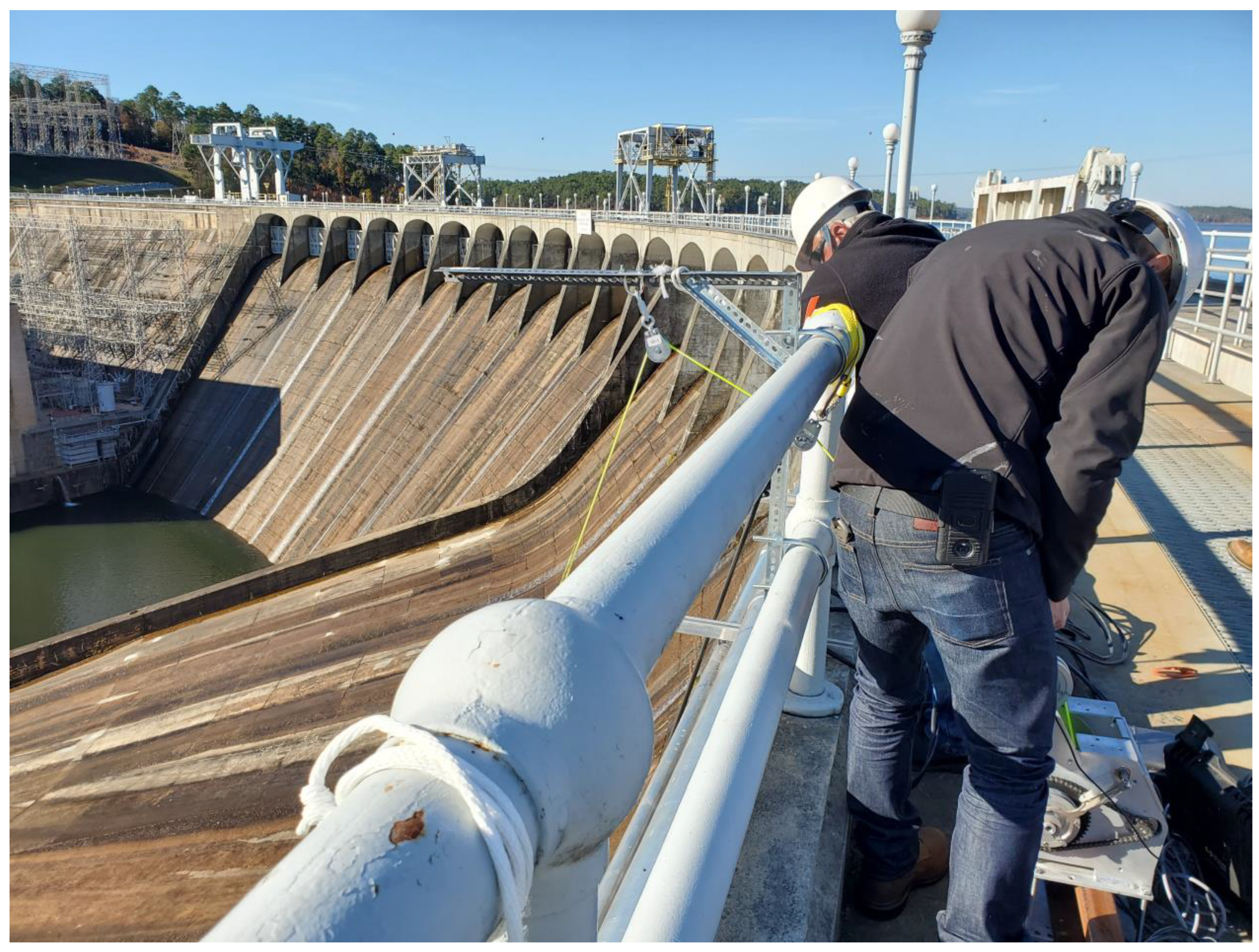
Figure 1.
Photograph showing crawler with GPR being lowered onto spillway and locations of example resurfaced concrete.
Figure 1.
Photograph showing crawler with GPR being lowered onto spillway and locations of example resurfaced concrete.

Figure 2.
Photograph of spillway surface showing significant spalling left of red line.

Figure 3.
Photograph of crawler with GPR integrated.

Figure 4.
Photographs showing (a) crawler with GPR being lowered onto spillway, (b) crawler with GPR collecting data across repaired concrete surface, and (c) data collection with iPad from top of dam with crawler with GPR in background.
Figure 4.
Photographs showing (a) crawler with GPR being lowered onto spillway, (b) crawler with GPR collecting data across repaired concrete surface, and (c) data collection with iPad from top of dam with crawler with GPR in background.

Figure 5.
Photographs show crawler with GPR being lowered onto spillway after implementation of 1 m boom.
Figure 5.
Photographs show crawler with GPR being lowered onto spillway after implementation of 1 m boom.

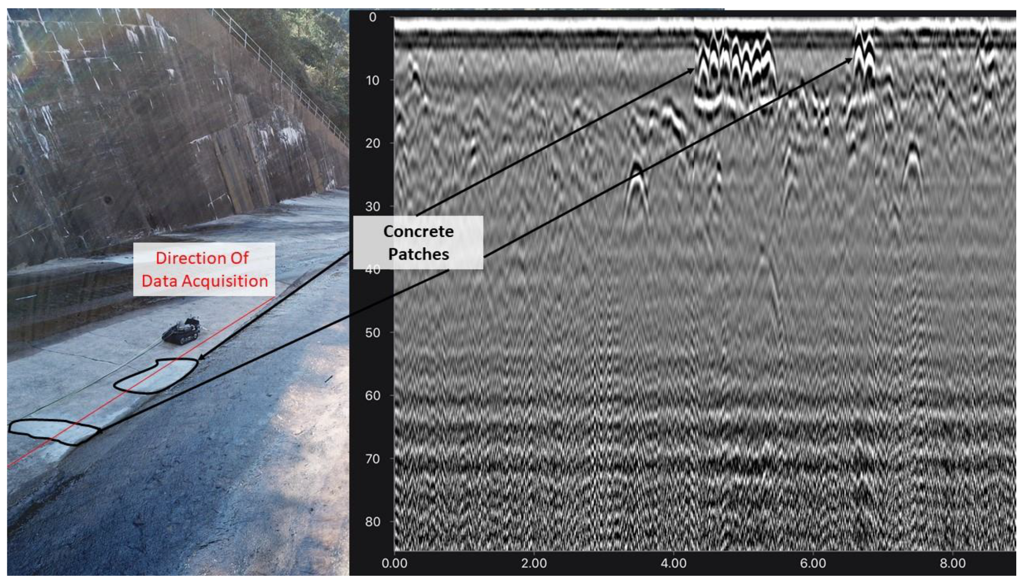
Figure 6.
GPR profile collected during robotic crawler deployment with (Right) response occurring near the upper central portion of the section shows narrow hyperbolic reflections from steel reinforcements embedded in portion of repaired concrete and (left) concrete patches of repair.
Figure 6.
GPR profile collected during robotic crawler deployment with (Right) response occurring near the upper central portion of the section shows narrow hyperbolic reflections from steel reinforcements embedded in portion of repaired concrete and (left) concrete patches of repair.

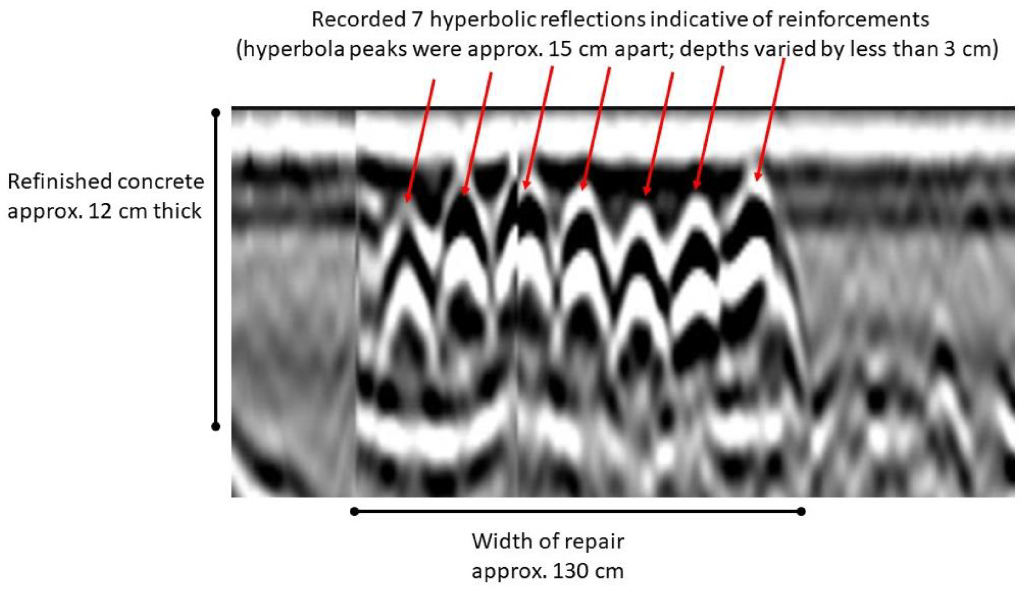
Figure 7.
GPR profile collected over refinished concrete indicating depth of old/new concrete interface, number of reinforcements, depth of reinforcements, and separation of reinforcements as indicated by hyperbolic reflection responses.
Figure 7.
GPR profile collected over refinished concrete indicating depth of old/new concrete interface, number of reinforcements, depth of reinforcements, and separation of reinforcements as indicated by hyperbolic reflection responses.

Disclaimer/Publisher’s Note: The statements, opinions and data contained in all publications are solely those of the individual author(s) and contributor(s) and not of MDPI and/or the editor(s). MDPI and/or the editor(s) disclaim responsibility for any injury to people or property resulting from any ideas, methods, instructions or products referred to in the content. |
© 2023 by the author. Licensee MDPI, Basel, Switzerland. This article is an open access article distributed under the terms and conditions of the Creative Commons Attribution (CC BY) license (https://creativecommons.org/licenses/by/4.0/).
Share and Cite
MDPI and ACS Style
Bigman, D.P. Evaluating the Feasibility of Robotic Crawler Deployed Ground Penetrating Radar to Assess Repairs of a Concrete Hydroelectric Dam Spillway in Alabama, USA. Water 2023, 15, 1858. https://doi.org/10.3390/w15101858
AMA Style
Bigman DP. Evaluating the Feasibility of Robotic Crawler Deployed Ground Penetrating Radar to Assess Repairs of a Concrete Hydroelectric Dam Spillway in Alabama, USA. Water. 2023; 15(10):1858. https://doi.org/10.3390/w15101858
Chicago/Turabian StyleBigman, Daniel P. 2023. "Evaluating the Feasibility of Robotic Crawler Deployed Ground Penetrating Radar to Assess Repairs of a Concrete Hydroelectric Dam Spillway in Alabama, USA" Water 15, no. 10: 1858. https://doi.org/10.3390/w15101858
Note that from the first issue of 2016, this journal uses article numbers instead of page numbers. See further details here.