
Modified Numerical Method for Improving the Calculation of Rill Detachment Rate
1
Guangxi Key Laboratory of Forest Ecology and Conservation, College of Forestry, Guangxi University, Nanning 530004, China
2
College of Water Resources and Civil Engineering, China Agricultural University, Beijing 100083, China
3
College of Resources and Environment, Tibet Agriculture and Animal Husbandry University, Linzhi 860000, China
4
College of Engineering, China Agricultural University, Beijing 100083, China
*
Author to whom correspondence should be addressed.
Water 2023, 15(10), 1875; https://doi.org/10.3390/w15101875
Submission received: 7 April 2023
/
Revised: 9 May 2023
/
Accepted: 12 May 2023
/
Published: 15 May 2023
(This article belongs to the Special Issue Rainfall and Water Flow-Induced Soil Erosion-Volume 2.0)
Abstract
:A rational calculation of the rill detachment rate (RDR) and an accurate simulation of the rill detachment process are important for determining the model parameters of hillslope erosion. Here, we found a difference between RDRs calculated using different methods that cannot be ignored. This study proposes a modified numerical method based on the dataset of the measured sediment concentrations along the rill length over a saturated loess soil slope to improve the calculation of RDR. For the saturated loess soil slope, the modified numerical RDR reduced the relative error from 58.3% to 4.6%, thereby demonstrating the efficiency of the modified numerical method. Furthermore, datasets of previous studies on different soil types and rill width verified the accuracy and applicability of the modified numerical method. A measurement strategy with more sampling points set at the forepart of the rill is proposed to enhance the calculation accuracy of RDR in accordance with the absolute error distribution between numerical and modified numerical RDRs. This study contributes to the literature by correcting previous data, improving data for subsequent measurements, and supplying a basis for the accurate estimation of RDR for rill erosion modeling.
1. Introduction
Soil erosion, as a key environmental issue globally, can lead to land degradation [1] and landslides [2,3]. The soil erosion processes comprehensively include soil detachment, entrainment, transport, and deposition [4]. As an erosive subprocess, soil detachment is the first step of soil erosion [5,6]. The soil detachment rate is an indispensable index for determining the process-oriented soil erosion, and it is an important parameter in soil erosion models, directly affecting their accuracy [7,8]. Therefore, the accurate measurement of soil detachment rate is very important. Previous studies found that the soil detachment rate could be obtained using some models that contain hydraulic parameters, such as stream power [9], unit stream power [10], and flow shear stress [11]. Furthermore, some studies verified that stream power and shear stress were recommended to predict the soil detachment rate at tillage [12], hillslope [13,14], and road surface [15]. However, these hydraulic parameters were hard to measure and complicated calculation, such that the soil detachment rate was conducted with low accuracy [12,13,14,15,16,17]. Thus, a simply calculated, convenient, and exact parameter should be considered to calculate the soil detachment rate.
Rill erosion has been incorporated into process-based erosion models because it is an important process of hillslope erosion [18,19,20]. The rill detachment rate (RDR) is a fundamental parameter for determining the rill erosion model. Some studies focused on determining the soil detachment rate of the entire slope [21,22,23]. Zhou et al. [21] studied the effect of sediment-laden rill flow on the soil detachment process and found that flow discharge was the most important factor influencing the RDR of the entire slope, followed by slope and sediment load. Liu et al. [22] studied the effect of different root types and planting density on RDRs over the entire soil slope during root growth time. The results showed that plants with fibrous roots could reduce RDR compared with plants with taproots, and the high-density treatment reduced RDR at the early growth stage, but had the opposite effect at the later stage. Ma et al. [23] studied the potential effects of root system and freeze–thaw on RDR over the entire slope of sandy loam and silty loam, respectively. The results indicated that the root system promoted RDR, but freeze–thaw reduced it. The poor measurement effect of RDR along the slope length led to many researchers studying the RDR on the entire soil slope. However, the distribution of RDR along the slope length is essential to determine the soil detachment process, before building the process-oriented model. Thus, a series of experiments under different underlying surface and hydraulic conditions were conducted to study the RDR distributed along the rill length, as well as the correlation between RDR and sediment concentration. The RDR exponentially decreased with the rill length [24,25]. Lei et al. [24] verified that RDRs exponentially decreased with the rill length using 8 m long rills (the width of 0.1 m). Shen et al. [26] also observed similar relationships with a 4 m flume (the width of 0.1 m) under different hydraulic conditions. Meanwhile, studies also found that RDRs linearly decreased with sediment load on different underlying surfaces or when using different measurement methods [6,27,28,29]. In addition, Chen et al. [30] found that RDRs of a partially thawed soil slope had piecewise functions with rill length, initially maintaining a constant value before exponentially decreasing with rill length. Consequently, studies on the accuracy of soil detachment rate calculation would affect the abovementioned assessment results directly and play a fundamental role in the study of rill erosion.
To date, two methods (the numerical method and the analytical method) have commonly been used to calculate RDR in the process-based erosion model [28]. According to the definition of RDR, a method was put forward consisting of the average RDR calculated by the numerical model between the sediment delivery rate and the distance of runoff in a selected rill segment, which was regarded as the RDR at the end point of this rill segment [24]. Hence, the numerical method is an approximate calculation method. The calculated error was determined by the length of rill segment. A shorter rill segment resulted in a smaller calculated error. The analytical method was derived from the function describing the relationship between sediment concentration and rill length in the WEPP (Water Erosion Prediction Project) model and the definition of RDR [31]. The analytical method could be used to calculate the RDR at the random length of rill. However, the analytical method based on a theoretical calculation requires a complex experimental and derivation process compared with the numerical method. Furthermore, the analytical method has certain limitations in its application to the different underlying surface conditions. For example, it is unfit for the calculation of the RDR of partially thawed soil. Thus, the numerical method is still the most commonly used and peer-recognized method at present. The accuracy of the numerical method must be improved to obtain an accurate RDR using an experimental dataset. However, methods for improving calculation of RDR measured using the numerical method have rarely been reported.
Here, we propose a modified numerical method to improve the accuracy of RDR calculation. Previous studies designed many different measurement lengths (8 m and 12 m) and sampling intervals (0.5 m, 1 m, 2 m, and 4 m) to determine the sediment concentrations distributed along the rill length [7,24,27,32,33,34]. To verify the accuracy of the modified numerical method, the analytical method was selected as a reference. To test the suitability of the modified numerical method, data from previous studies under different designed conditions and different soil types were reprocessed. Overall, this study had the following objectives: (1) to quantify the uncertainty in using the numerical method to calculate RDR, (2) to propose and verify a modified numerical method to improve the accuracy of RDR calculation, and (3) to present a strategy of measuring sediment concentrations during the rill erosion process to improve the accuracy of RDR calculation. This study is meaningful to developing simulations of the rill detachment process and improving rill erosion prediction models.
2. Methods and Data Source
2.1. Rill Erosion Process
The Water Erosion Prediction Project (WEPP) model describes the rill sediment yield [35,36,37] according to the hypothesis of detachment and transport coupling [38,39]. Thus, the following equation was proposed to model the rill erosion process [7,40]:
where c represents the sediment concentration (kg·m−3), x is the rill length (m), A denotes the maximum sediment concentration that reaches sediment transport capacity (kg·m−3), and B represents the decrease rate of sediment load.
2.2. Numerical Method for Calculating Rill Detachment Rate
The RDR refers to the amount of soil eroded from a unit area during a unit time [11,28,41]. Sediment concentration increases with rill length until reaching the sediment transport capacity. The surface area of the rill segment from x to x + Δx is approximately a trapezoid and can be estimated as (w + w + Δw) Δx/2 = Δx (w + Δw/2). The relevant sediment concentration changes from c to c + Δc. The average RDR of the increased rill segment (Δx) is estimated as follows [24,31,33]:
where Q denotes the rill flow rate (Q = wq, m3·s−1), w represents the rill width (m), q represents the unit-width discharge rate (m2·s−1), and DrN is the RDR calculated using the numerical method (kg·m−2·s−1).
2.3. Analytical Method for Calculating Rill Detachment Rate
The RDR can be computed analytically by combining Equations (1) and (2) in accordance with the definition of RDR. In Equation (2), Δw/2 becomes 0 when Δx approaches 0. Then, Equation (2) can be rewritten as follows:
where Dr represents the RDR calculated using the analytical method (kg·m−2·s−1). Substituting Equation (1) into Equation (3) yields the analytical estimation of the RDR:
where a denotes the maximum analytical RDR (kg·m−2·s−1), and b represents the decrease rate of RDR (m−1).
The analytical RDR can also be calculated with sediment concentration by combing Equations (1) and (4):
where d represents the maximum analytical RDR (kg·m−2·s−1), and g expresses the decrease rate of the RDR with the increase in sediment concentration (m·s−1). Lei et al. [24] and Chen et al. [28] introduced detailed derivation processes of the analytical method.
2.4. Principle of Modified Numerical Method
According to the numerical calculating principle of RDR, using the sediment concentrations (0, c1, c2, …, cn) at different rill distances and rill lengths (0, x1, x2, …, xn), the numerical values of RDRs (0, DrN1, DrN2, …, DrNn) can be calculated as follows:
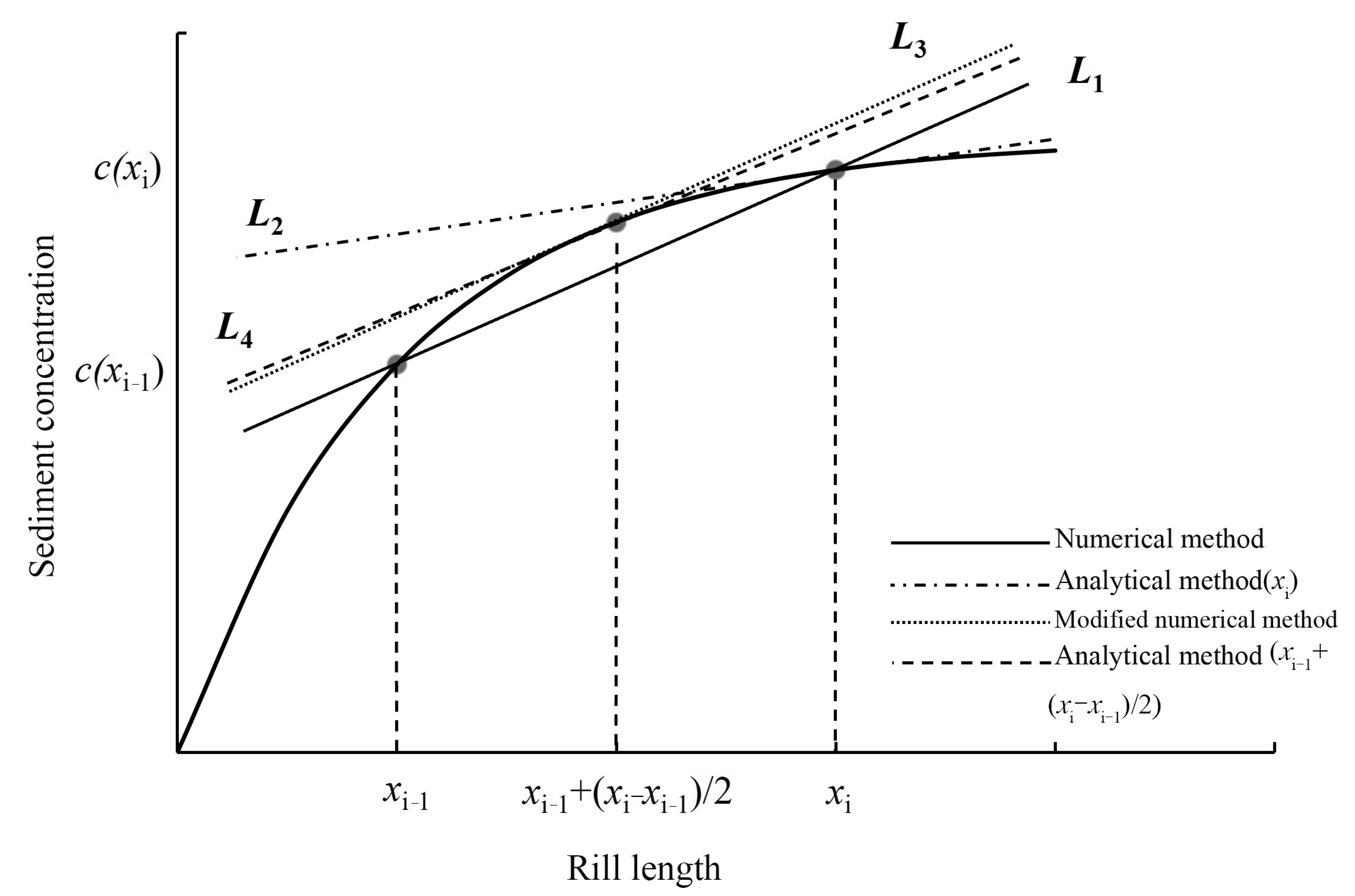
where xi is the rill length at location i (m), ci is the sediment concentration at location i (kg·m−3), and DrNi denotes the RDR calculated by the numerical method at location i (kg·m−2·s−1). The sediment concentration rises from c(i−1) to ci with the rill segment increasing from xi−1 to xi. Thus, the ratio between the sediment delivery rate (q(ci − c(i−1))) and the distance of runoff flow (xi − xi−1) corresponds to the average numerical RDR of this segment, which is shown as the gradient of L1 (Figure 1). The gradient of L1 can be approximately considered the numerical RDR at xi when the increment from xi−1 to xi is relatively low. The gradient of L2 is the tangent line of the sediment delivery curve (c(x)) at xi, which represents the analytical RDR at xi. The gradient of L1 is theoretically higher than that of L2. Thus, the numerical RDR is always higher than the analytical value.
Thus, c(x) is a monotonically increasing function of x. Therefore, a point c (x = ξ) always satisfies the following equation among the intervals of (xi − xi−1):
Here, we assume that the midpoint (x = xi−1 + (xi − xi−1)/2) of the interval (xi − xi−1) is used to assign the assuming point (x = ξ) (Figure 1). The gradient of L3 represents the modified numerical value of RDR at the midpoint, which is equal to the gradient of L1 based on Equation (8). Meanwhile, the modified numerical RDR is also close to the analytical value (which is shown as L4) at the midpoint. This modification theoretically results in consistent numerical and analytical values.
The numerical and the modified numerical RDRs are compared to the analytical RDR at the same point (x) by fitting the following equations to quantify the differences:
where DrN represents the numerical RDR (kg·m−2·s−1), Dr1 and Dr2 are the analytical RDRs calculated by rill length and sediment concentration (kg·m−2·s−1) respectively, DrM is the modified numerical RDR (kg·m−2·s−1), and h, k, and m are the regression coefficients which reflect the relative errors between each pair of methods.
Furthermore, absolute errors between the numerical and the modified numerical RDRs in the ranges of rill length of 0–4 m and 4–8 m are analyzed in the study. The average absolute errors of the two sections are calculated as follows:
where AE(0–4) and AE(4–8) denote the average absolute error between the numerical and the modified numerical RDRs in the range of rill length of 0–4 m and 4–8 m, kg·m−2·s−1, respectively.
2.5. Basic Dataset
The datasets of the rill erosion process and the numerical RDRs on saturated loess soil slopes under a rill width of 0.1 m were used to evaluate the effectiveness of the modified numerical method. The principles and details of experimental devices for acquiring this dataset were introduced by Huang et al. [42] and Huang et al. [33]. Briefly, a soil flume and a saturated soil device were supplied to form saturated loess soil slopes for soil erosion experiments. According to the USDA texture classification, the experimental soil is a typical silt loam, which has particle fractions of 23.80% sand, 64.57% silt, and 11.63% clay particles; it was collected from the Ansai Research Station (109°19′23″ E, 36°51′30″ N) of Soil and Water Conservation, Chinese Academy of Sciences. Four slope gradients (5°, 10°, 15°, and 20°) and three flow rates (2, 4, and 8 L·min−1) were set for the experiments. The water flow was introduced into the steady flow flume, and then introduced into the rill 1, 2, 4, and 8 m away from the rill outlet. In each test, four 300 mL steel cups were used to collect runoff samples, after the water flow at the outlet of the rill was stable. Each sampling process took 30~60 s. Subsequently, the samples were left for 24 h, and the supernatant was filtered out. The sediment concentrations of the runoff samples were measured using the oven-drying method at 105 °C. The rill erosion process on saturated loess soil slopes was studied in Huang et al. [33] (Table 1). Subsequently, the analytical RDRs on saturated loess soil slopes could be computed using the rill length (Equation (4)) and sediment concentration (Equation (6)). Meanwhile, the RDRs calculated using the numerical method on saturated loess soil slopes were investigated in Huang et al. [6] (Table 2).
2.6. Statistical Analysis
The statistical analyses were conducted using SPSS software (ver.22.0). One-way analysis of variance was used to analyze differences in numerical RDRs, analytical RDRs, and modified numerical RDRs. The difference was significant at the 0.05 level. Linear regression analysis was used to determine the proportional coefficients among numerical RDRs, modified numerical RDRs, and analytical RDRs.
3. Results
3.1. Comparison of Numerical, Analytical, and Modified Numerical Methods
The numerical RDRs, analytical values, and modified numerical values under a flow rate of 4 L·min−1 and slope gradients of 5°, 10°, 15°, and 20° were fitted by Equation (4) to verify the accuracy of the principle of the modified numerical method and study the rill detachment processes determined by three groups of datasets (Figure 2). All determining coefficients were higher than 0.80, and the values of p were lower than 0.05, which indicated the good exponential function relationships among the numerical, analytical, and modified numerical RDRs and rill length. All three methods described the rill detachment processes well. Figure 2 shows that the curves determined using the modified numerical method were closer to those determined using the analytical method than those determined using the numerical method. Both analytical and modified numerical RDRs were significantly lower than the numerical RDRs (p < 0.01). This disparity increased with the slope gradient.
3.2. Improvement Effect of the Modified Numerical Method
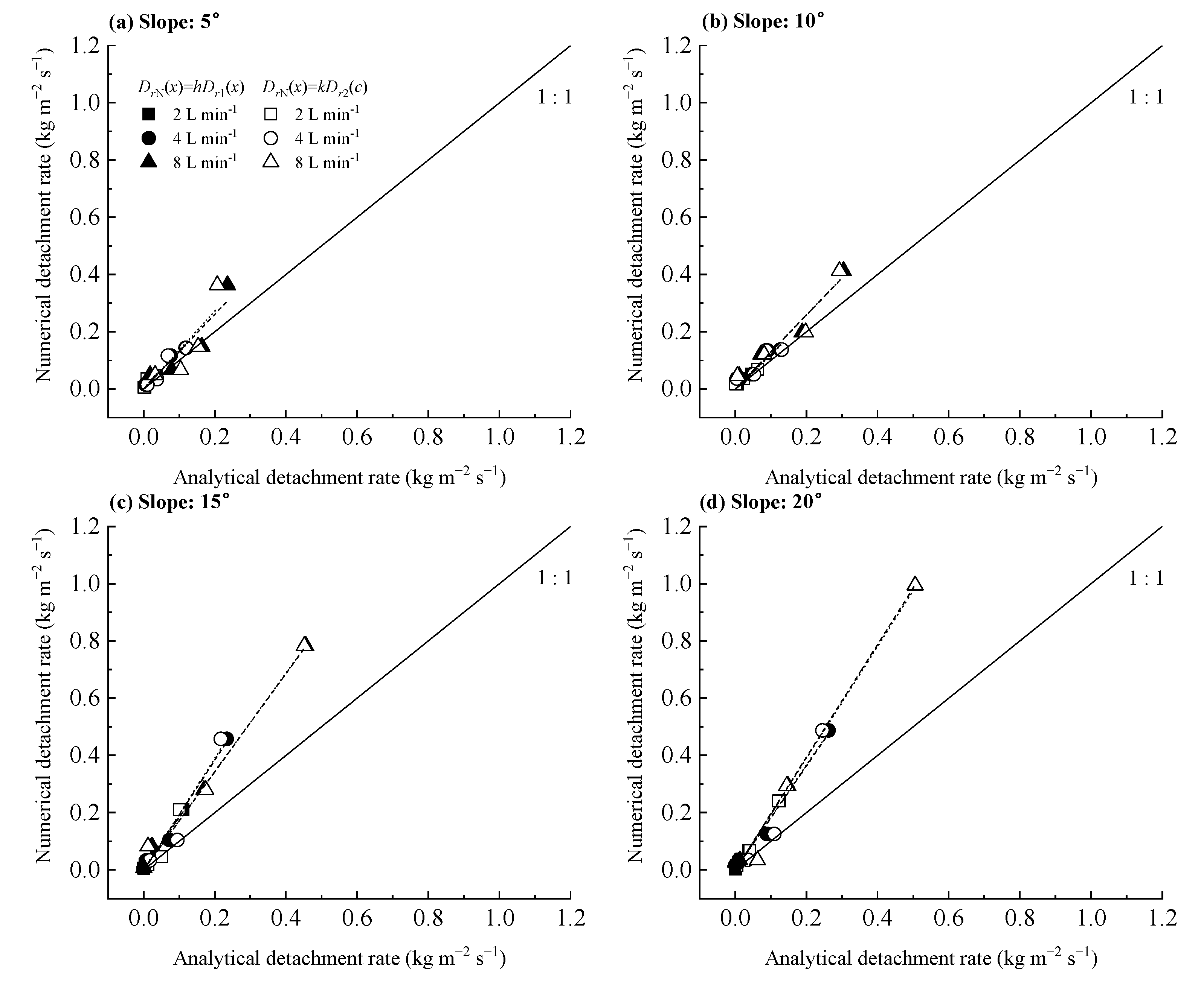
In order to quantify the errors between numerical RDRs and analytical values, the analytical RDRs calculated using the rill length, sediment concentration, and numerical values were fitted using Equations (8) and (9) under the designed flow rates and slope gradients. The fitting results are drawn in Figure 3 and listed in Table 3. The high determining coefficients (0.92–0.99, 0.84–0.99) of the fitting lines indicate that the three groups of RDRs were fitted well by Equations (8) and (9). The values of h and k reached the maximum at the slope gradient of 10°. The numerical RDRs were overestimated by 14.4–97.0% (with a mean relative error of 58.3%) compared with the analytical RDRs over saturated loess soil slopes, indicating the need for an improvement in the accuracy of the numerical RDR.
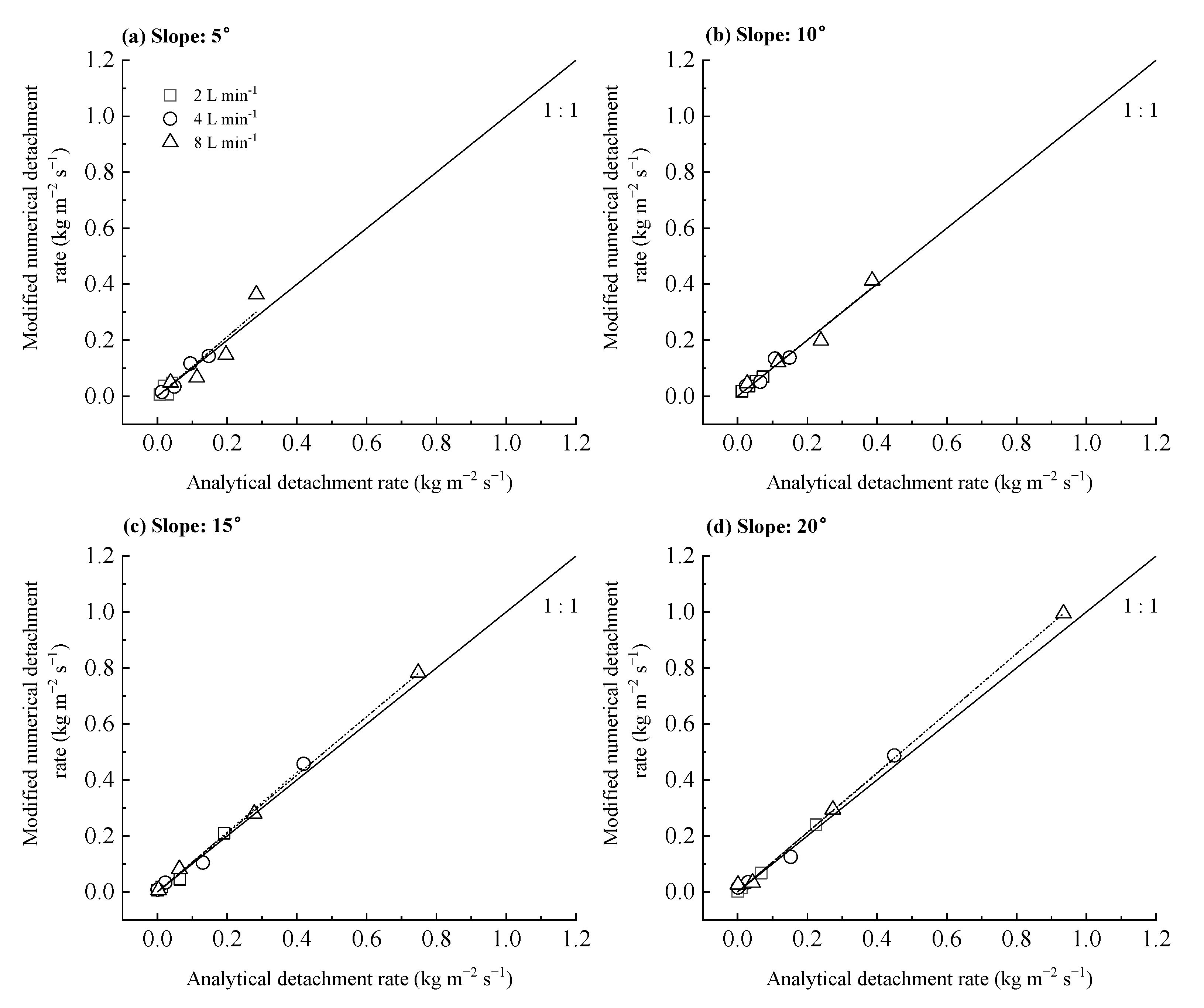
In order to study the improvement effect of the modified numerical method, the analytical values were fitted with the modified numerical values using Equation (10); the fitting results are drawn in Figure 4 and listed in Table 4. The high determining coefficients (0.84–0.99) of the fitting lines indicated that two groups of RDRs fitted well with Equation (10). All fitting curves were close to the 1:1 line. The values of parameter m ranged from 0.930 to 1.068 with a mean value of 1.033 and were significantly lower than those of parameter h in Table 3 (p < 0.01). The relative errors between analytical and modified numerical RDRs ranged from 0.7% to 7.0%, with a mean value of 4.6%. The differences between analytical RDRs and modified numerical values were insignificant (p > 0.05). The above results indicated that the modified numerical method led to a good improvement in calculating RDR on saturated loess soil slopes.
4. Discussion
4.1. Necessity and Application of Modified Numerical Method
The analytical method needs to confirm the curve of sediment concentration changes with rill length before calculating the RDR, which requires a complex experimental process (including measuring sediment transport capacity and sediment concentrations along the rill length). To date, most scientists have directly measured and estimated the soil detachment rate using the numerical method because of its convenience [43,44]. The results of saturated loess soil slopes revealed that the relative errors of numerical RDRs compared with analytical RDRs were overestimated by 58.3% (mean level). The inconsistency of the two methods showed the poor accuracy of the numerical method, which limits the application of the numerical RDR. The modified numerical method in this study greatly improved the accuracy of RDR (with a mean relative error of 4.6% compared to the analytical method), which could enhance the simulation accuracy of the rill detachment process on saturated loess soil slopes under a rill width of 0.1 m. A series of data from previous studies were collected to evaluate the applicability of the modified numerical method. In accordance with these data of previous studies, the following steps were conducted to obtain the numerical, modified numerical, and analytical RDRs: (1) the numerical RDRs were calculated using the measured sediment concentrations; (2) the numerical RDRs were modified in accordance with the principle of the modified numerical method; (3) the analytical RDRs at the modified rill length were calculated in accordance with the parameters obtained using the measured sediment concentrations and rill lengths.
Under the designed rill width of 0.1 m, two types of soil (purple soil and loess soil) were used to study rill erosion process. Chen et al. [28] calculated RDRs using numerical and analytical methods over purple soil slopes. In the study of purple soil, the proportional coefficients between the numerical and the analytical RDRs (h) and those between the modified numerical and the analytical RDRs (m) are shown in Table 5. The mean proportional coefficient between the numerical and the analytical RDRs of purple soil was 1.13 ± 0.08, which was significantly higher than the mean proportional coefficient (0.99 ± 0.06) between the modified numerical and the analytical RDRs (p < 0.01). Simultaneously, the average relative error of RDR dropped from 13.2% to 1.1% when using the modified numerical method at the purple soil. Furthermore, Lei et al. [40] and Zhang et al. [27] studied the sediment concentrations and numerical RDRs of loess soil under different factors (slope, flow rate, and rill length) using the rare Earth elements tracer method. The mean proportional coefficients among the three methods derived from Lei et al. [40] and Zhang et al. [27] are listed in Table 5, respectively. The mean values of h in the two studies were 1.04 ± 0.04 and 1.10 ± 0.06, which were significantly higher than m (0.99 ± 0.03, 1.00 ± 0.05, p < 0.01), respectively. The above results indicated that the modified numerical method successfully reduced the test error and was suitable for measuring RDRs of purple soil and loess soil slopes under a rill width of 0.1 m.
Other scientists studied the sediment delivery and soil detachment with different rill widths and soil types [45,46]. Huang et al. [45] studied the sediment delivery of Russell silt loam and Saybrook silt loam under different slope lengths and flow rates with a flume width of 0.2 m. As shown in Table 5, the mean proportional coefficients between the numerical and analytical RDRs of Russell silt loam and Saybrook silt loam were 1.68 ± 0.58 and 1.34 ± 0.24, higher than those between the modified numerical and analytical RDRs (0.99 ± 0.06 and 1.06 ± 0.11). Polyakov and Nearing [46] studied the change in sediment concentrations with slope length over Carmi loam soil slope under different flow rates and a flume width of 0.61 m. The proportional coefficients of h were clearly larger than m, indicating the effective improvement of the modified numerical method.
In summary, the values of parameter h were greater than the values of parameter m in the above studies. Specifically, the RDR calculated using the numerical method in the previous study was high compared to the true value, which affected the calculation of other parameters, such as soil erodibility, soil detachment capacity, and critical shear stress. The modified numerical RDRs were lower than the numerical RDRs and close to the analytical RDRs, indicating that the modified numerical method significantly improved the accuracy of calculating RDR on the basis of measured data. Simultaneously, researchers can similarly correct published or unpublished historical data to provide a good dataset, which will facilitate the establishment of good soil erosion prediction models. To date, the application of this method under other underlying surfaces and detachment rates of other erosion types remains to be studied.
4.2. Measurement Strategy for Improving Accuracy of Rill Detachment Rate Calculation
As shown in Figure 2, the RDR of saturated loess soil slope in the first 4 m determined the curve trend, representing the stage with most errors occurring. Because the measured slope lengths were at least 8 m in previous studies, the average absolute errors between the numerical and modified numerical RDRs at the slope lengths of 0−4 m and 4−8 m were calculated to verify the applicability of measurement strategy. As listed in Table 6, the average absolute errors of RDRs for the 0−4 m slope length were significantly larger than those for the 4−8 m slope length under five soil types and three flume widths (p < 0.05). Overall, the average absolute errors of RDRs in the first 4 m were 0.18−131.63 (mean: 12.93) times larger than those at the last 4 m (Table 6). Therefore, the measurement accuracy of sediment concentrations in the range of slope length of 0−4 m was the key factor influencing the RDR measurement on the saturated loess soil slope. Thus, the sampling points of sediment concentrations should be increased at the forepart of the slope. This measurement strategy of sediment concentrations could enhance the calculation accuracy of RDR and reduce the cost of the experiment. Further studies should adopt this strategy to avoid densely increasing the sampling points of sediment concentrations throughout the slope.
5. Conclusions
The numerical RDR at a certain interval of the rill was modified to obtain the modified numerical RDR at the midpoint location, which efficiently reduced the relative error of saturated loess soil from 58.3% to 4.6%. According to the datasets of previous studies, the modified numerical method with different soil types and rill widths showed a wide applicability and good accuracy. Moreover, on the basis of the absolute error distribution between numerical and modified numerical RDRs, a measurement strategy with more sampling points set at the forepart of the rill was proposed to enhance the accuracy of RDR calculation. These results eventually indicated the remarkable performance of the modified numerical method when simulating the rill detachment process using experimental data, serving as a foundation for improving rill erosion models. Furthermore, researchers can apply the measurement strategy and the modified numerical method to determine the soil detachment rates of other erosion types, as well as correct published or unpublished historical rill erosion data, to provide a good dataset for establishing a process-oriented soil erosion prediction model.
Author Contributions
Conceptualization, Y.H., M.Z. and T.L.; methodology, Y.H., M.Z. and T.L.; software, Y.H. and M.Z.; validation, Y.H. and D.W.; formal analysis, Y.H., M.Z. and D.W.; investigation, Y.H. and M.Z.; resources, Y.H. and T.L.; data curation, Y.H. and M.Z.; writing—original draft preparation, Y.H. and M.Z.; writing—review and editing, Y.H., M.Z., D.W., F.L. and W.W.; visualization, Y.H.; supervision, Y.H.; project administration, Y.H. and T.L.; funding acquisition, Y.H. and W.W. All authors have read and agreed to the published version of the manuscript.
Funding
This work was financially supported by the “Project funded by China Postdoctoral Science Foundation” under Project No. 2022M710404 and the “National Natural Science Foundation of China” under Project No. 42207389 and 41571257.
Data Availability Statement
Data can be made available on request.
Conflicts of Interest
The authors declare no conflict of interest.
References
- Nowak, A.; Schneider, C. Environmental characteristics, agricultural land use, and vulnerability to degradation in Malopolska Province (Poland). Sci. Total Environ. 2017, 590, 620–632. [Google Scholar] [CrossRef] [PubMed]
- Xu, L.; Coop, M.R.; Zhang, M.; Wang, G. The mechanics of a saturated silty loess and implications for landslides. Eng. Geol. 2018, 236, 29–42. [Google Scholar] [CrossRef]
- Zhao, Q.; Wang, A.; Yu, Z.; Yu, J.; Liu, Y.; Zhang, G.; Liu, G.; Wang, P.; Ding, S. Factors contributing to rill erosion of forest roads in a mountainous watershed. J. Environ. Manag. 2023, 326, 116829. [Google Scholar] [CrossRef] [PubMed]
- Du, H.; Dou, S.; Deng, X.; Xue, X.; Wang, T. Assessment of wind and water erosion risk in the watershed of the Ningxia-Inner Mongolia Reach of the Yellow River, China. Ecol. Indic. 2016, 67, 117–131. [Google Scholar] [CrossRef]
- Yimer, F.; Messing, I.; Ledin, S.; Abdelkadir, A. Effects of different land use types on infiltration capacity in a catchment in the highlands of Ethiopia. Soil Use Manag. 2008, 24, 344–349. [Google Scholar] [CrossRef]
- Huang, Y.; Wang, W.; Lei, T.; Li, F.; Li, J. Saturation effect on the distribution of rill detachment rate. Eur. J. Soil Sci. 2021, 72, 2076–2087. [Google Scholar] [CrossRef]
- Chen, X.-Y.; Huang, Y.-H.; Zhao, Y.; Mo, B.; Mi, H.-X. Comparison of loess and purple rill erosions measured with volume replacement method. J. Hydrol. 2015, 530, 476–483. [Google Scholar] [CrossRef]
- Wang, J.F.; Yang, Y.F.; Liu, G.B.; Wang, B.; Zhang, F.B.; Fang, N.F. Investigating the effects of herbaceous root systems on the soil detachment process at the species level. Sci. Total Environ. 2023, 859, 160196. [Google Scholar] [CrossRef]
- Hairsine, P.B.; Rose, C.W. Modeling water erosion due to overland flow using physical principles: 2. Rill flow. Water Resour. Res. 1992, 28, 245–250. [Google Scholar] [CrossRef]
- Morgan, R.P.C.; Qinton, J.N.; Smith, R.E.; Govers, G.; Poesen, J.W.A.; Auerswald, K.; Chisci, G.; Torri, D.; Styczen, M.E. The European soil erosion model (EUROSEM): A dynamic approach for predicting sediment transport from fields and small catchments—Reply. Earth Surf. Process. Landf. 1999, 24, 567–568. [Google Scholar] [CrossRef]
- Nearing, M.A.; Bradford, J.M.; Parker, S.C. Soil detachment by shallow flow at low slopes. Soil Sci. Soc. Am. J. 1991, 55, 339–344. [Google Scholar] [CrossRef]
- Sun, J.; Zhang, N.; Shi, M.; Zhai, Y.; Wu, F. The effects of tillage induced surface roughness, slope and discharge rate on soil detachment by concentrated flow: An experimental study. Hydrol. Process. 2021, 35, e14261. [Google Scholar] [CrossRef]
- Xiao, H.; Liu, G.; Liu, P.; Zheng, F.; Zhang, J.; Hu, F. Response of soil detachment rate to the hydraulic parameters of concentrated flow on steep loessial slopes on the Loess Plateau of China. Hydrol. Process. 2017, 31, 2613–2621. [Google Scholar] [CrossRef]
- Wu, B.; Wang, Z.-l.; Zhang, Q.-W.; Shen, N.; Liu, J. Response of soil detachment rate by raindrop-affected sediment-laden sheet flow to sediment load and hydraulic parameters within a detachment-limited sheet erosion system on steep slopes on Loess Plateau, China. Soil Tillage Res. 2019, 185, 9–16. [Google Scholar] [CrossRef]
- Cao, L.; Zhang, K.; Zhang, W. Detachment of road surface soil by flowing water. Catena 2009, 76, 155–162. [Google Scholar] [CrossRef]
- Rehman, Z.U.; Khalid, U.; Ijaz, N.; Mujtaba, H.; Haider, A.; Farooq, K.; Ijaz, Z. Machine learning-based intelligent modeling of hydraulic conductivity of sandy soils considering a wide range of grain sizes. Eng. Geol. 2022, 311, 106899. [Google Scholar] [CrossRef]
- Ijaz, N.; Ijaz, Z.; Rehman, Z.U. Recycling of paper/wood industry waste for hydromechanical stability of expansive soils: A novel approach. J. Clean. Prod. 2022, 348, 131345. [Google Scholar] [CrossRef]
- Shi, Z.H.; Fang, N.F.; Wu, F.Z.; Wang, L.; Yue, B.J.; Wu, G.L. Soil erosion processes and sediment sorting associated with transport mechanisms on steep slopes. J. Hydrol. 2012, 454, 123–130. [Google Scholar] [CrossRef]
- Li, Z.; Fang, H. Impacts of climate change on water erosion: A review. Earth-Sci. Rev. 2016, 163, 94–117. [Google Scholar] [CrossRef]
- Shen, N.; Wang, Z.; Zhang, F.; Zhou, C. Response of Soil Detachment Rate to Sediment Load and Model Examination: A Key Process Simulation of Rill Erosion on Steep Loessial Hillslopes. Int. J. Environ. Res. Public Health 2023, 20, 2839. [Google Scholar] [CrossRef]
- Zhou, C.; Shen, N.; Zhang, F.; Delang, C.O. Soil detachment by sediment-laden rill flow interpreted using three experimental design methods. Catena 2022, 215, 106332. [Google Scholar] [CrossRef]
- Liu, J.; Zhou, Z.; Liu, J.; Su, X. Effects of root density on soil detachment capacity by overland flow during one growing season. J. Soils Sediments 2022, 22, 1500–1510. [Google Scholar] [CrossRef]
- Ma, J.; Li, Z.; Sun, B.; Ma, B.; Zhang, L. Modeling soil detachment capacity by rill flow under the effect of freeze–thaw and the root system. Nat. Hazards 2022, 112, 207–230. [Google Scholar] [CrossRef]
- Lei, T.W.; Zhang, Q.W.; Zhao, J. Laboratory experiments and computational method of soils detachment rate of sediment loading flow in rills. Trans. Chin. Soc. Agric. Eng. 2001, 17, 24–27. (In Chinese) [Google Scholar]
- Merten, G.H.; Nearing, M.A.; Borges, A.L.O. Effect of sediment load on soil detachment and deposition in rills. Soil Sci. Soc. Am. J. 2001, 65, 861–868. [Google Scholar] [CrossRef]
- Shen, N.; Wang, Z.; Zhang, Q.; Wu, B.; Wang, D.; Zhang, Q.; Liu, J. Quantifying the Contribution of Sediment Load to Soil Detachment Rate by Sediment-Laden Rill Flow. Soil Sci. Soc. Am. J. 2017, 81, 1526–1536. [Google Scholar] [CrossRef]
- Zhang, Q.; Lei, T.; Zhao, J. Estimation of the detachment rate in eroding rills in flume experiments using an REE tracing method. Geoderma 2008, 147, 8–15. [Google Scholar] [CrossRef]
- Chen, X.-Y.; Huang, Y.-H.; Zhao, Y.; Mo, B.; Mi, H.-X.; Huang, C.-H. Analytical method for determining rill detachment rate of purple soil as compared with that of loess soil. J. Hydrol. 2017, 549, 236–243. [Google Scholar] [CrossRef]
- Han, Z.; Chen, X.; Li, Y.; Chen, S.; Gu, X.; Wei, C. Quantifying the rill-detachment process along a saturated soil slope. Soil Tillage Res. 2020, 204, 104726. [Google Scholar] [CrossRef]
- Chen, C.; Lei, T.; Ban, Y. Influence of slope, flow rate, and thawed depth on soil detachment rate in partially thawed black soils. J. Hydrol. 2021, 603, 127009. [Google Scholar] [CrossRef]
- Lei, T.W.; Zhang, Q.W.; Zhao, J.; Xia, W.S.; Pan, Y.H. Soil detachment rates for sediment loaded flow in rills. Am. Soc. Agric. Biol. Eng. 2002, 45, 1897–1903. [Google Scholar] [CrossRef]
- Chen, X.-Y.; Zha, Y.; Mi, H.-X.; Mo, B. Estimating rill erosion process from eroded morphology in flume experiments by volume replacement method. Catena 2016, 136, 135–140. [Google Scholar] [CrossRef]
- Huang, Y.; Li, F.; Wang, W.; Li, J. Rill erosion processes on a constantly saturated slope. Hydrol. Process. 2020, 34, 3955–3965. [Google Scholar] [CrossRef]
- Han, Z.; Chen, X.; Li, Y.; Chen, S.; Gu, X.; Wei, C. Estimating rill erosion and sediment transport processes along a saturated purple soil slope. Can. J. Soil Sci. 2021, 101, 507–516. [Google Scholar] [CrossRef]
- Lane, L.J.; Nearing, M.A. Erosion component. In USDA-Water Erosion Prediction Project: Hillslope Profile Model Documentation; Lafayette, W., Ed.; Soil Erosion Research Laboratory: West Lafayette, IN, USA, 1989. [Google Scholar]
- Nearing, M.A.; Foster, G.R.; Lane, L.J.; Finkner, S.C. A process-based soil erosion model for USDA-water prediction project technology. Am. Soc. Agric, Biol. Eng. 1989, 32, 1587–1593. [Google Scholar] [CrossRef]
- Flanagan, D.C.; Nearing, M.A. USDA Water Erosion Prediction Project Hillslope and Watershed Model Documentation; NSERL Rep. No. 10; Lafayette, W., Ed.; USDAARS National Soil Erosion Research Laboratory: West Lafayette, IN, USA, 1995.
- Foster, G.R.; Meyer, L.D. A closed-form soil erosion equation for upland areas. In Sedimentation Symposium to Honor Professor H. A. Einstein; University of California: Oakland, CA, USA, 1972. [Google Scholar]
- Foster, G.R.; Meyer, L.D. Transport of soil particles by shallow flow. Am. Soc. Agric. Biol. Eng. 1972, 15, 99–102. [Google Scholar] [CrossRef]
- Lei, T.W.; Zhang, Q.W.; Zhao, J.; Nearing, M.A. Tracing sediment dynamics and sources in eroding rills with rare earth elements. Eur. J. Soil Sci. 2006, 57, 287–294. [Google Scholar] [CrossRef]
- Gimenez, R.; Govers, G. Flow detachment by concentrated flow on smooth and irregular beds. Soil Sci. Soc. Am. J. 2002, 66, 1475–1483. [Google Scholar] [CrossRef]
- Huang, Y.; Chen, X.; Li, F.; Zhang, J.; Lei, T.; Li, J.; Chen, P.; Wang, X. Velocity of water flow along saturated loess slopes under erosion effects. J. Hydrol. 2018, 561, 304–311. [Google Scholar] [CrossRef]
- Wang, Y.; Luo, J.; Zheng, Z.; Li, T.; He, S.; Zhang, X.; Wang, Y.; Liu, T. Assessing the contribution of the sediment content and hydraulics parameters to the soil detachment rate using a flume scouring experiment. Catena 2019, 176, 315–323. [Google Scholar] [CrossRef]
- Shen, N.; Wang, Z.; Zhang, Q.; Wu, B.; Liu, J. Modelling the process of soil detachment by rill flow on steep loessial hillslopes. Earth Surf. Process. Landf. 2020, 45, 1240–1247. [Google Scholar] [CrossRef]
- Huang, C.H.; Bradford, J.M.; Laflen, J.M. Evaluation of the detachment-transport coupling concept in the WEEP rill erosion equation. Soil Sci. Soc. Am. J. 1996, 60, 734–739. [Google Scholar] [CrossRef]
- Polyakov, V.O.; Nearing, M.A. Sediment transport in rill flow under deposition and detachment conditions. Catena 2003, 51, 33–43. [Google Scholar] [CrossRef]
Figure 1.
Schematic of the modified numerical method for calculating RDR.

Figure 2.
Comparing three rill detachment processes determined using numerical, analytical, and modified numerical detachment rates (RDRs) under a flow rate of 4 L·min−1 of different slope gradients: (a) 5°, (b) 10°, (c) 15°, and (d) 20°.
Figure 2.
Comparing three rill detachment processes determined using numerical, analytical, and modified numerical detachment rates (RDRs) under a flow rate of 4 L·min−1 of different slope gradients: (a) 5°, (b) 10°, (c) 15°, and (d) 20°.

Figure 3.
Comparison between numerical and analytical rill detachment rates over saturated loess soil slopes of different slope gradients: (a) 5°, (b) 10°, (c) 15°, and (d) 20°.
Figure 3.
Comparison between numerical and analytical rill detachment rates over saturated loess soil slopes of different slope gradients: (a) 5°, (b) 10°, (c) 15°, and (d) 20°.

Figure 4.
Comparison between modified numerical and analytical rill detachment rates over saturated loess soil slopes of different slope gradients: (a) 5°, (b) 10°, (c) 15°, and (d) 20°.
Figure 4.
Comparison between modified numerical and analytical rill detachment rates over saturated loess soil slopes of different slope gradients: (a) 5°, (b) 10°, (c) 15°, and (d) 20°.


Table 1.
Fitted rill erosion process with Equation (1) on saturated loess soil slopes [33].
Table 1.
Fitted rill erosion process with Equation (1) on saturated loess soil slopes [33].
| Slope (°) | Flow Rate (L·min−1) | Parameters | Coefficient of Determination (R2) | |
|---|---|---|---|---|
| A (kg·m−3) | B (m−1) | |||
| 5 | 2 | 465.34 | 0.32 | 0.92 |
| 4 | 623.89 | 0.44 | 0.99 | |
| 8 | 696.29 | 0.37 | 0.97 | |
| 10 | 2 | 800.81 | 0.32 | 0.98 |
| 4 | 800.02 | 0.33 | 0.99 | |
| 8 | 767.42 | 0.48 | 0.99 | |
| 15 | 2 | 907.93 | 1.09 | 0.99 |
| 4 | 965.44 | 1.17 | 0.99 | |
| 8 | 929.38 | 0.99 | 0.99 | |
| 20 | 2 | 1027.49 | 1.19 | 0.99 |
| 4 | 1071.35 | 1.08 | 0.99 | |
| 8 | 1054.62 | 1.23 | 0.99 | |
Table 2.
Numerical RDRs along the eroding rills over saturated loess soil slopes [6].
Table 2.
Numerical RDRs along the eroding rills over saturated loess soil slopes [6].
| Slope (°) | Flow Rate (L·min−1) | Rill Detachment Rate (kg·m−2·s−1) | |||
|---|---|---|---|---|---|
| 1 m Rill Length | 2 m Rill Length | 4 m Rill Length | 8 m Rill Length | ||
| 5 | 2 | 0.047 | 0.007 | 0.036 | 0.006 |
| 4 | 0.144 | 0.117 | 0.035 | 0.015 | |
| 8 | 0.363 | 0.148 | 0.066 | 0.049 | |
| 10 | 2 | 0.069 | 0.053 | 0.036 | 0.017 |
| 4 | 0.138 | 0.135 | 0.051 | 0.036 | |
| 8 | 0.413 | 0.198 | 0.121 | 0.045 | |
| 15 | 2 | 0.210 | 0.046 | 0.018 | 0.006 |
| 4 | 0.458 | 0.104 | 0.033 | 0.008 | |
| 8 | 0.783 | 0.279 | 0.082 | 0.006 | |
| 20 | 2 | 0.241 | 0.067 | 0.015 | 0.002 |
| 4 | 0.487 | 0.125 | 0.035 | 0.016 | |
| 8 | 0.994 | 0.294 | 0.033 | 0.026 | |
Table 3.
Proportional coefficients of analytical rill detachment rates (RDRs) compared with numerical RDRs.
Table 3.
Proportional coefficients of analytical rill detachment rates (RDRs) compared with numerical RDRs.
| Slope (°) | Flow Rate (L·min−1) | Proportional Coefficients | Coefficients of Determination | pr | ps | ||
|---|---|---|---|---|---|---|---|
| h | k | Rr2 | Rs2 | ||||
| 5 | 2 | 1.468 | 1.523 | 0.92 | 0.84 | 0.043 | 0.081 |
| 4 | 1.304 | 1.293 | 0.98 | 0.97 | <0.001 | 0.002 | |
| 8 | 1.305 | 1.360 | 0.94 | 0.90 | 0.006 | 0.014 | |
| 10 | 2 | 1.176 | 1.144 | 0.98 | 0.96 | 0.001 | 0.003 |
| 4 | 1.222 | 1.193 | 0.97 | 0.94 | 0.002 | 0.006 | |
| 8 | 1.293 | 1.295 | 0.98 | 0.97 | 0.001 | 0.001 | |
| 15 | 2 | 1.831 | 1.843 | 0.98 | 0.94 | <0.001 | 0.033 |
| 4 | 1.917 | 1.948 | 0.99 | 0.97 | <0.001 | 0.017 | |
| 8 | 1.714 | 1.719 | 0.99 | 0.99 | <0.001 | 0.003 | |
| 20 | 2 | 1.930 | 1.952 | 0.99 | 0.99 | <0.001 | 0.002 |
| 4 | 1.816 | 1.834 | 0.99 | 0.97 | <0.001 | 0.016 | |
| 8 | 1.970 | 1.952 | 0.99 | 0.99 | <0.001 | 0.004 | |
Notes: The values of h represent the proportional coefficients of numerical detachment rates compared with analytical detachment rates calculated by rill length. The values of k represent the proportional coefficients of numerical detachment rates compared with modified analytical detachment rates calculated by sediment concentration.
Table 4.
Proportional coefficients of analytical rill detachment rates (RDRs) compared with modified numerical RDRs.
Table 4.
Proportional coefficients of analytical rill detachment rates (RDRs) compared with modified numerical RDRs.
| Slope (°) | Flow Rate (L·min−1) | Proportional Coefficient | Coefficient of Determination | p |
|---|---|---|---|---|
| m | R2 | |||
| 5 | 2 | 0.930 | 0.68 | 0.054 |
| 4 | 1.028 | 0.97 | 0.001 | |
| 8 | 1.062 | 0.91 | 0.007 | |
| 10 | 2 | 0.988 | 0.99 | <0.001 |
| 4 | 1.016 | 0.96 | 0.002 | |
| 8 | 1.007 | 0.98 | <0.001 | |
| 15 | 2 | 1.062 | 0.98 | <0.001 |
| 4 | 1.068 | 0.99 | <0.001 | |
| 8 | 1.044 | 0.99 | <0.001 | |
| 20 | 2 | 1.064 | 0.99 | <0.001 |
| 4 | 1.057 | 0.99 | <0.001 | |
| 8 | 1.064 | 0.99 | <0.001 |
Notes: The values of m represent the proportional coefficients of modified numerical detachment rates compared with modified analytical detachment rates.
Table 5.
Proportional coefficients of numerical/modified numerical rill detachment rates compared with analytical RDRs.
Table 5.
Proportional coefficients of numerical/modified numerical rill detachment rates compared with analytical RDRs.
| Study | Soil Type | Rill Width (m) | Slope | Flow Rate (L·min−1) | Proportional Coefficient | Coefficient of Determination | ph | pm | ||
|---|---|---|---|---|---|---|---|---|---|---|
| h | m | Rh2 | Rm2 | |||||||
| Chen et al. [28] | Purple soil | 0.1 | 10° | 4 | 1.06 | 1.00 | 0.93 | 0.93 | <0.001 | <0.001 |
| 8 | 0.93 | 0.86 | 0.95 | 0.96 | <0.001 | <0.001 | ||||
| 15° | 2 | 1.22 | 1.08 | 0.96 | 0.96 | <0.001 | <0.001 | |||
| 4 | 1.19 | 1.05 | 0.97 | 0.98 | <0.001 | <0.001 | ||||
| 8 | 1.16 | 0.98 | 0.97 | 0.99 | <0.001 | <0.001 | ||||
| 20° | 2 | 1.19 | 1.01 | 0.96 | 0.97 | <0.001 | <0.001 | |||
| 4 | 1.11 | 0.94 | 0.99 | 0.99 | <0.001 | <0.001 | ||||
| 8 | 1.10 | 0.95 | 0.96 | 0.97 | <0.001 | <0.001 | ||||
| 25° | 2 | 1.16 | 1.01 | 0.97 | 0.97 | <0.001 | <0.001 | |||
| 4 | 1.24 | 1.07 | 0.97 | 0.98 | <0.001 | <0.001 | ||||
| 8 | 1.09 | 0.93 | 0.95 | 0.97 | <0.001 | <0.001 | ||||
| Lei et al. [40] | Loess soil | 0.1 | 10° | 4 | 1.00 | 1.00 | 0.95 | 0.95 | <0.001 | <0.001 |
| 8 | 1.03 | 0.99 | 0.91 | 0.91 | <0.001 | <0.001 | ||||
| 12 | 1.00 | 0.99 | 0.99 | 0.99 | <0.001 | <0.001 | ||||
| 15° | 4 | 1.16 | 1.01 | 0.98 | 0.98 | <0.001 | <0.001 | |||
| 8 | 0.99 | 0.99 | 0.96 | 0.96 | <0.001 | <0.001 | ||||
| 12 | 0.99 | 0.98 | 0.97 | 0.97 | <0.001 | <0.001 | ||||
| 20° | 4 | 1.04 | 0.98 | 0.94 | 0.94 | <0.001 | <0.001 | |||
| 8 | 1.03 | 0.98 | 0.89 | 0.9 | <0.001 | <0.001 | ||||
| 12 | 1.04 | 0.99 | 0.97 | 0.97 | <0.001 | <0.001 | ||||
| 25° | 4 | 1.06 | 0.97 | 0.91 | 0.91 | <0.001 | <0.001 | |||
| 8 | 1.06 | 0.99 | 0.95 | 0.95 | <0.001 | <0.001 | ||||
| 12 | 1.06 | 0.99 | 0.96 | 0.96 | <0.001 | <0.001 | ||||
| Zhang et al. [27] | Loess soil | 0.1 | 17.62% | 8 | 1.15 | 1.05 | 0.93 | 0.92 | <0.001 | <0.001 |
| 12 | 1.12 | 1.09 | 0.99 | 0.98 | <0.001 | <0.001 | ||||
| 26.78% | 2 | 1.03 | 0.98 | 0.97 | 0.96 | <0.001 | <0.001 | |||
| 4 | 1.04 | 0.99 | 0.99 | 0.95 | <0.001 | <0.001 | ||||
| 8 | 1.10 | 1.01 | 0.98 | 0.99 | <0.001 | <0.001 | ||||
| 36.38% | 2 | 1.08 | 0.97 | 0.96 | 0.96 | <0.001 | <0.001 | |||
| 4 | 1.06 | 0.94 | 0.96 | 0.97 | <0.001 | <0.001 | ||||
| 8 | 1.12 | 0.99 | 0.99 | 0.99 | <0.001 | <0.001 | ||||
| 46.60% | 2 | 1.19 | 1.02 | 0.98 | 0.98 | <0.001 | <0.001 | |||
| 4 | 1.20 | 1.03 | 0.99 | 0.99 | <0.001 | <0.001 | ||||
| 8 | 1.02 | 0.92 | 0.95 | 0.96 | <0.001 | <0.001 | ||||
| Huang et al. [45] | Russell silt loam | 0.2 | 6.30% | 15.1 | 2.10 | 1.04 | 0.87 | 0.84 | 0.069 | 0.081 |
| 22.7 | 2.40 | 1.05 | 0.99 | 0.88 | 0.066 | 0.061 | ||||
| 30.2 | 1.17 | 0.95 | 0.9 | 0.8 | 0.039 | 0.042 | ||||
| 37.8 | 1.05 | 0.92 | 0.92 | 0.83 | 0.029 | 0.031 | ||||
| Saybrook silt loam | 0.2 | 2.40% | 7.6 | 1.55 | 1.20 | 0.94 | 0.87 | 0.065 | 0.066 | |
| 15.1 | 1.46 | 1.05 | 0.97 | 0.95 | 0.026 | 0.027 | ||||
| 22.7 | 1.01 | 0.94 | 0.99 | 0.99 | <0.001 | <0.001 | ||||
| Polyakov and Nearing [46] | Carmi loam | 0.61 | 7% | 6 | 1.40 | 1.09 | 0.79 | 0.77 | 0.045 | 0.052 |
| 9 | 1.29 | 0.89 | 0.91 | 0.90 | 0.045 | 0.053 | ||||
Notes: The values of h represent the proportional coefficients of numerical detachment rates compared with analytical detachment rates. The values of m represent the proportional coefficients of modified numerical detachment rates compared with modified analytical detachment rates. The values of Rh2 and Rm2 denote the coefficients of determination.
Table 6.
Average absolute errors between the numerical and the modified numerical rill detachment rates.
Table 6.
Average absolute errors between the numerical and the modified numerical rill detachment rates.
| Study | Soil Type | Rill Width (m) | Slope | Flow Rate (L·min−1) | Average Absolute Error (kg·m−2·s−1) | |
|---|---|---|---|---|---|---|
| 0–4 m | 4–8 m | |||||
| Huang et al. [6,33] | Loess soil | 0.1 | 5 | 2 | 0.061 | 0.331 |
| 4 | 0.201 | 0.043 | ||||
| 8 | 0.411 | 0.073 | ||||
| 10 | 2 | 0.105 | 0.044 | |||
| 4 | 0.197 | 0.080 | ||||
| 8 | 0.499 | 0.063 | ||||
| 15 | 2 | 0.211 | 0.002 | |||
| 4 | 0.464 | 0.005 | ||||
| 8 | 0.835 | 0.018 | ||||
| 20 | 2 | 0.247 | 0.004 | |||
| 4 | 0.498 | 0.008 | ||||
| 8 | 1.053 | 0.008 | ||||
| Chen et al. [28] | Purple soil | 0.1 | 10° | 4 | 0.055 | 0.017 |
| 8 | 0.125 | 0.061 | ||||
| 15° | 2 | 0.063 | 0.021 | |||
| 4 | 0.147 | 0.044 | ||||
| 8 | 0.382 | 0.066 | ||||
| 20° | 2 | 0.072 | 0.011 | |||
| 4 | 0.168 | 0.023 | ||||
| 8 | 0.368 | 0.074 | ||||
| 25° | 2 | 0.066 | 0.014 | |||
| 4 | 0.196 | 0.038 | ||||
| 8 | 0.349 | 0.048 | ||||
| Lei et al. [40] | loess soil | 0.1 | 10° | 4 | - | - |
| 8 | 0.241 | 0.070 | ||||
| 12 | 0.353 | 0.320 | ||||
| 15° | 4 | 0.228 | 0.073 | |||
| 8 | - | - | ||||
| 12 | 0.416 | 0.507 | ||||
| 20° | 4 | 0.196 | 0.122 | |||
| 8 | 0.343 | 0.099 | ||||
| 12 | 0.555 | 0.067 | ||||
| 25° | 4 | 0.198 | 0.120 | |||
| 8 | 0.375 | 0.113 | ||||
| 12 | 0.583 | 0.095 | ||||
| Zhang et al. [27] | Loess soil | 0.1 | 17.62% | 8 | 0.165 | 0.064 |
| 12 | 0.229 | 0.172 | ||||
| 26.78% | 2 | 0.086 | 0.048 | |||
| 4 | 0.165 | 0.095 | ||||
| 8 | 0.396 | 0.162 | ||||
| 36.38% | 2 | 0.115 | 0.037 | |||
| 4 | - | - | ||||
| 8 | 0.491 | 0.116 | ||||
| 46.60% | 2 | 0.142 | 0.021 | |||
| 4 | 0.276 | 0.041 | ||||
| 8 | 0.477 | 0.112 | ||||
| Huang et al. [45] | Russell silt loam | 0.2 | 6.30% | 15.1 | 0.030 | 0.011 |
| 22.7 | 0.045 | 0.027 | ||||
| 30.2 | 0.058 | 0.030 | ||||
| 37.8 | 0.067 | 0.043 | ||||
| Saybrook silt loam | 0.2 | 2.40% | 7.6 | 0.016 | 0.014 | |
| 15.1 | 0.049 | 0.029 | ||||
| 22.7 | 0.051 | 0.039 | ||||
| Polyakov and Nearing [46] | Carmi loam | 0.61 | 7% | 6 | - | - |
| 9 | 0.005 | 0.002 | ||||
Disclaimer/Publisher’s Note: The statements, opinions and data contained in all publications are solely those of the individual author(s) and contributor(s) and not of MDPI and/or the editor(s). MDPI and/or the editor(s) disclaim responsibility for any injury to people or property resulting from any ideas, methods, instructions or products referred to in the content. |
© 2023 by the authors. Licensee MDPI, Basel, Switzerland. This article is an open access article distributed under the terms and conditions of the Creative Commons Attribution (CC BY) license (https://creativecommons.org/licenses/by/4.0/).
Share and Cite
MDPI and ACS Style
Huang, Y.; Zhao, M.; Wan, D.; Lei, T.; Li, F.; Wang, W. Modified Numerical Method for Improving the Calculation of Rill Detachment Rate. Water 2023, 15, 1875. https://doi.org/10.3390/w15101875
AMA Style
Huang Y, Zhao M, Wan D, Lei T, Li F, Wang W. Modified Numerical Method for Improving the Calculation of Rill Detachment Rate. Water. 2023; 15(10):1875. https://doi.org/10.3390/w15101875
Chicago/Turabian StyleHuang, Yuhan, Mingquan Zhao, Dan Wan, Tingwu Lei, Fahu Li, and Wei Wang. 2023. "Modified Numerical Method for Improving the Calculation of Rill Detachment Rate" Water 15, no. 10: 1875. https://doi.org/10.3390/w15101875
Note that from the first issue of 2016, this journal uses article numbers instead of page numbers. See further details here.