Article

Design of a Self-Supporting Liner for the Renovation of a Headrace Tunnel at Chivor Hydropower Project

by
David A. del Río
1,2,
Johann A. Caballero
1,2,
Jessica T. Muñoz
1,2,
Nhora Cecilia Parra-Rodriguez
1,2,
César Nieto-Londoño
3,
Rafael E. Vásquez
3,* and
Ana Escudero-Atehortua
3
1
South America Strategic Business Unit, AES Corporation, Santiago de Chile 7550000, Chile
2
AES Colombia, Calle 100 No. 19-54 Oficina 901, Bogotá 110111, Colombia
3
School of Engineering, Universidad Pontificia Bolivariana, Medellín 050031, Colombia
*
Author to whom correspondence should be addressed.
Water 2023, 15(3), 409; https://doi.org/10.3390/w15030409
Submission received: 18 November 2022 / Revised: 10 January 2023 / Accepted: 16 January 2023 / Published: 19 January 2023
(This article belongs to the Special Issue Advances in Hydraulic Engineering Management)

Abstract

:
Ensuring access to affordable, reliable, sustainable, and modern energy, as declared in the United Nations’ Agenda 2030, requires both the inclusion of new renewable energy sources, and the renovation of existing hydropower infrastructure, since this resource is considered a key strategy to support flexibility in electric grids with high penetrations of variable generation. This paper addresses the design of a self-supporting lining for the renovation of a headrace tunnel, that has been affected by a buckling event, in order to extend the operating life of the Chivor Hydropower Project, located in Colombia. Studies performed by AES Corporation about the buckling events that affected the headrace tunnel and the condition assessment are first described. Then, the design alternatives to renovate this important part of the hydropower plant’s infrastructure are presented in a general way. The detailed design and construction planning for the selected alternative are then illustrated by showing some calculations used in hydropower design. Such a renovation project is one of the first of its class in Colombia and goes from studies of the buckling events to the design of a modern lining that will be constructed while keeping the 1000-MW (6% of Colombia’s demand) hydropower plant in operation conditions, in order to extend its life for 50 more years, which represents an example for managers and practitioners of large-scale hydraulic engineering projects.

1. Introduction

According to the United Nations, human population has been growing at an annual rate greater than 1% per year [1], which implies that energy consumption has been growing also at an estimated average rate of 1.7% per year from 2020 to 2030 [2], requiring the energy sector to accelerate its transformation to net zero to meet this rising demand in a sustainable way [3]. Such energy transformation implies an increase in renewables within the share, including hydropower that represents the largest source of renewable electricity globally [4,5], since the current pace of progress is insufficient to achieve the Sustainable Development Goal (SDG) 7 “Affordable and clean energy” by 2030, as stated by the United Nations in the The Sustainable Development Goals Report 2022 [6]. Concerns for securing sustainable energy arose two decades ago at the World Water Council that was held in Kyoto, Japan by 2003 [7]. By then several issues were identified to be solved during the following years, including the availability of new and renovated infrastructure around the hydropower resource, as is being investigated nowadays [8,9,10], since this energy source has an established role in the energy sector [11].
Regarding infrastructure related to hydropower plants, several authors have reported research and development works on such projects, with a particular interest on headrace tunnels and penstocks [12] during the last ten years. For instance, Schleiss and Manso [13] developed procedures for the design and deployment of relief valves to reduce the bucking risk when conduction tunnels are emptied. Tun and Singal [14] reported several constructive alternatives to reduce buckling and collapse risks in tunnels. Panthi and Basnet [15] reviewed and assessed factors for designing conduction tunnels through failure analysis of previous cases, providing design criteria for hydropower projects in Scandinavia. Kawamura et al. [16] analyzed the tunnels of a 50-year old hydropower plant, and highlighted the importance of life extension projects of existing installations. Bonapace et al. [17] reported the renovation project for the penstock of the Kaunertal hydropower plant (390 MW), located in Austria, that started operation in 1965. Yang et al. [18] studied the stability and geological conditions of deep tunnels and their linings for the Jinping II hydropower project in China. Xiao and Zhao [19] analyzed the linings of the penstock within a rock-collapse area for the Hua’an hydropower plant, located at Fujian, China. Sheikh and Saif [20] proposed the use of a Steel Fibre-Reinforced Shotcrete (SFRS) in the penstock for the Gulpur hydropower project, in Pakistan. Liu et al. [21] investigated the failure mechanisms and steel strengthening effect for a tunnel lining using the Finite Element Method (FEM). Ref. [22] presented the use of a submerged wall to be used in combination with the intake gates for replacing the penstock shutoff valves at the hydropower plant Schneiderau in Austria.
Design and construction of headrace tunnels and penstocks for hydropower plants have evolved during the last 30 years. In the mid 1990s, inspection and testing guidelines to decrease the probability of failures in existing penstocks where provided [23], and different buckling models where studied by Omara et al. [24] to be used in rehabilitation processes of existing facilities. During the 2000s, Jian-Guo et al. [25] compared different standards used for designing conduction tunnels, and included works from from China, Russia, Japan, and the United States. Bobet and Nam [26] developed an analytical solution that describes the interaction between liner, ground, and pores in pressure tunnels. Vasilikis and Karamanos [27] investigated the structural stability of thin-walled steel cylinders under external pressure loads. Hachem and Schleiss [28] proposed new requirements for the design of pressure tunnels by analyzing the fluid-structure interaction phenomenon.
During the last ten years, modern approaches and tools have been used for the design of tunnels and penstocks in hydropower plants. For instance, Valdeolivas and Mosquera [29] developed a finite-element-based procedure for assessing the liner stability of a hydroelectric steel pressure tunnel. Lin et al. [30] proposed a nonlinear analysis method for the design of reinforcement systems for tunnel bifurcations with complex geometries. Cerjak et al. [31] proposed a solution for the qualification of materials based on failure cases in hydropower tunnels and penstocks. Simanjuntak et al. [32] used the finite element method to study the stresses and deformations that appear because of the construction process. Li and Li [33], Zhang et al. [34], and Yang et al. [18] reported risk studies risks for the construction of a deep conduction tunnel for the Jinping II Hydropower Station. Pachoud and Schleiss [35] studied stresses and displacements in steel-lined tunnels, considering the anisotropy of the rock, by using finite elements. Bobet and Yu [36] also considered anisotropy and obtained the analytic solution for the computation of stresses and displacements in a steel-lined tunnel. Palmström and Broch [37] reported experiences of a 100-year period with construction of unlined tunnels in Norway. Kravanja [38] presented the optimization process for the design of a high-pressure penstock at the Kozjak hydropower plant (Slovenia). Wang et al. [39] proposed the use of pre-stressed concrete linings for a conduction tunnel for the Songhua Water Transfer Project in Jilin, China. Haddouch et al. [40] used neural networks and genetic algorithms for the optimized design of steel penstocks that are exposed and supported by using ring girders. Ma et al. [41] reported a model for the fracture process of concrete, in order to provide a reference for penstock assessment and maintenance at the Three Gorges Hydropower Station.
Most works that are found within the scientific literature regarding the design and renovation of hydropower headrace tunnels and penstocks refer to territories with vast hydro resources such as China, Norway, Switzerland, Slovenia, the Himalayas, among others. This demonstrates that the interest to perform renovation of hydropower facilities has been growing around the world during the last decades, however, for Latin America there are no reports regarding the renovation of these tunnels at large-scale hydropower plants. Nonetheless, although the current works are not oriented to renovation and life extension for this region, there are reports devoted to the hydro resource and hydropower stations which demonstrates the interest in contributing such experiences from the region to the scientific community. Diaz-Arellano et al. [42] analyzed changes in high-altitude lake ecosystems caused mainly by pressure for the use of water resource between several actors, including hydropower use. Angarita et al. [43] developed an integrated methodology to assess impacts of hydropower projects for wetlands in the Magdalena River basin, Colombia. Anderson et al. [44] reported a rapid grow of hydropower projects in the Amazonas River basin, using information from Brazil, Colombia, Bolivia, Ecuador and Peru. Diáz et al. [45] reported how river fragmentation for the development of new hydropower projects in Chile will affect ecologic functions in the Andean ecosystems. Atkins [46] reported the conundrum generated by diverse points of view of different stakeholders regarding the sustainability of hydropower projects in Brazil.
In the case of Colombia, the energy mix relies mostly on hydropower, which accounts for around 70% of the installed capacity [47]. This poses the need to develop an climate-change adaptation plan of the power sector [47], using new power generation strategies and renovating hydropower infrastructure since it has been growing within the American continent [10,48]. Cortés-Borda et al. [49] performed a study on social perception of hydropower sustainability, and indicated that large hydropower plants can operate in the long term while causing a positive impact on ecosystems and the local society, when appropriate sustainability strategies are used. Regarding this matter, del Río et al. [50,51] recently recently the Chivor Life Extension Project (CLEP) that has been implemented to extend the life of an existing 1000-MW (6% of Colombia’s demand) power plant, contributing to a sustainable energy supply for the future in the country.
In the pursuit of a decarbonized economy, hydropower has been identified as a key renewable energy source [10,52], but more than 50% of hydropower plants were commissioned more than 40 years ago [53], which leads to the need of renovating existing large-scale plants because several installations are ageing and require renovations to keep them operating [54,55]. This work addresses a new contribution, presented as a case report, on this matter for the fulfilment of the 7th SDG: “Ensure access to affordable, reliable, sustainable and modern energy for all”, represented by the renovation of a conduction tunnel for the Chivor Hydropower Project, performed by AES Colombia, within the strategy that is being developed to operate this large-scale hydropower plant during 50 more years, which represents an example for managers and practitioners of hydraulic engineering projects. The organization of the paper is as follows. In Section 2 the hydropower plant is described, and the structural design process, based on the analysis of several alternatives for the headrace tunnel’s lining, is exemplified. Section 3 shows the state and assessment of the conduction tunnel Chivor II and results of the detailed design. Section 4 contains the discussion, and finally, conclusions are presented in Section 5.

2. Materials and Methods

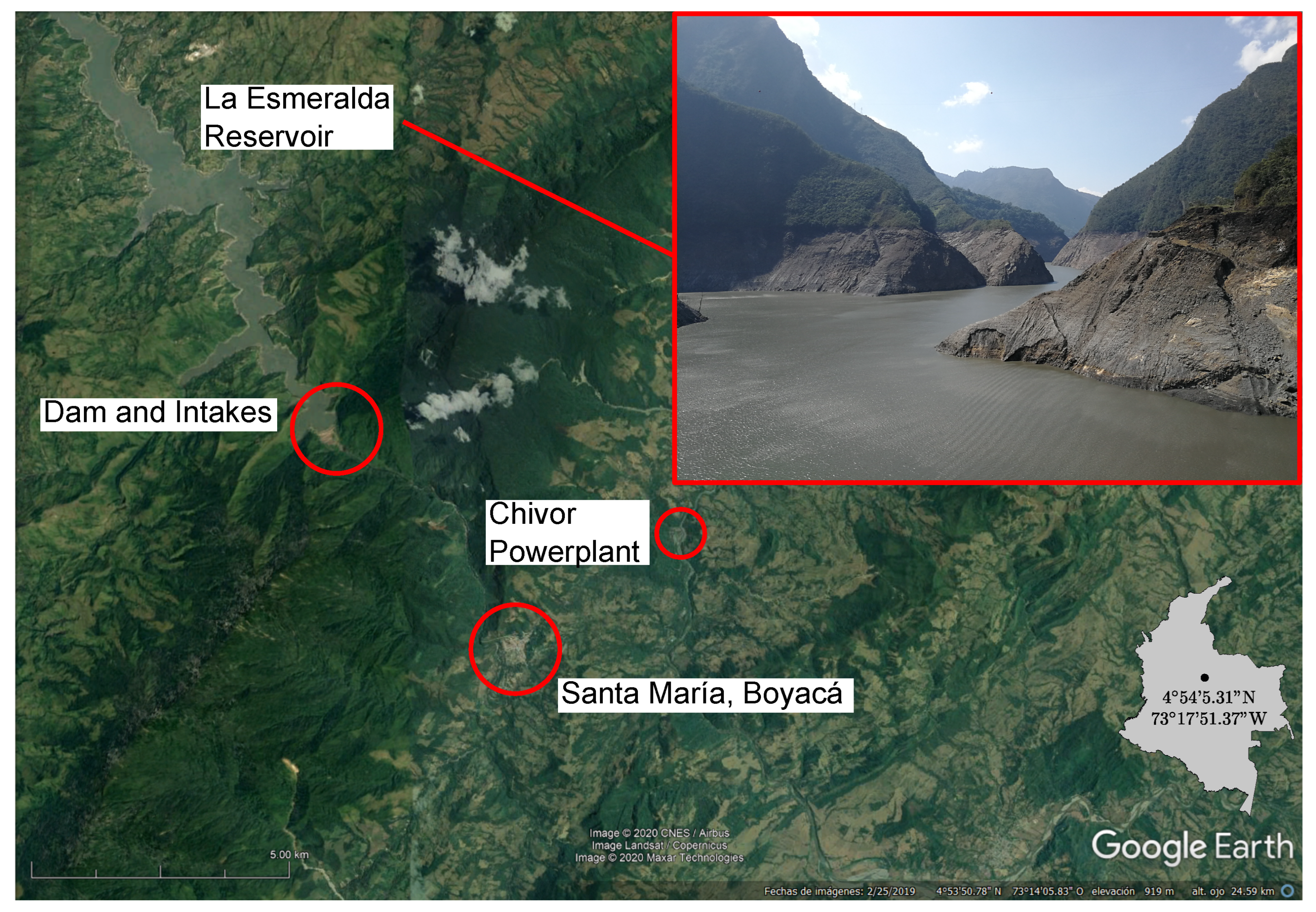
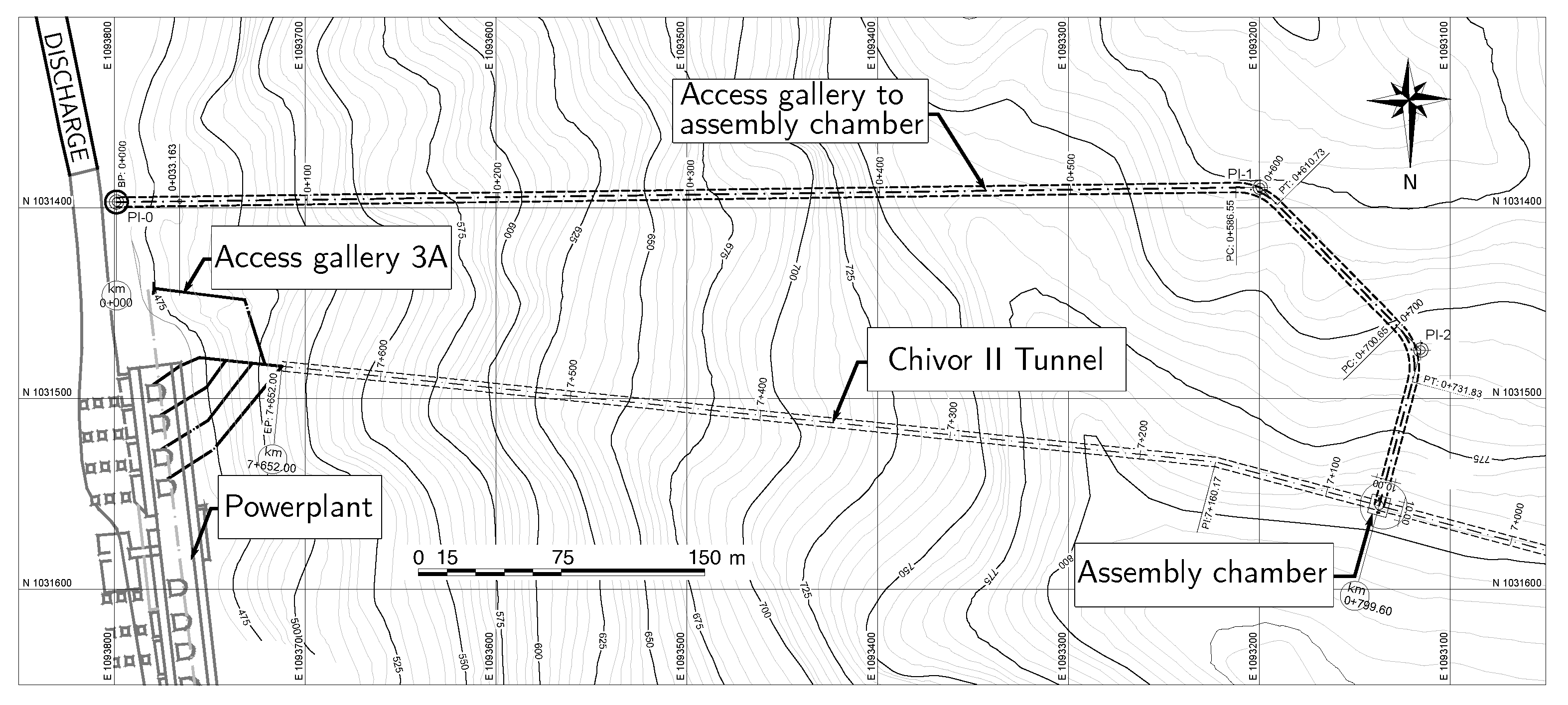
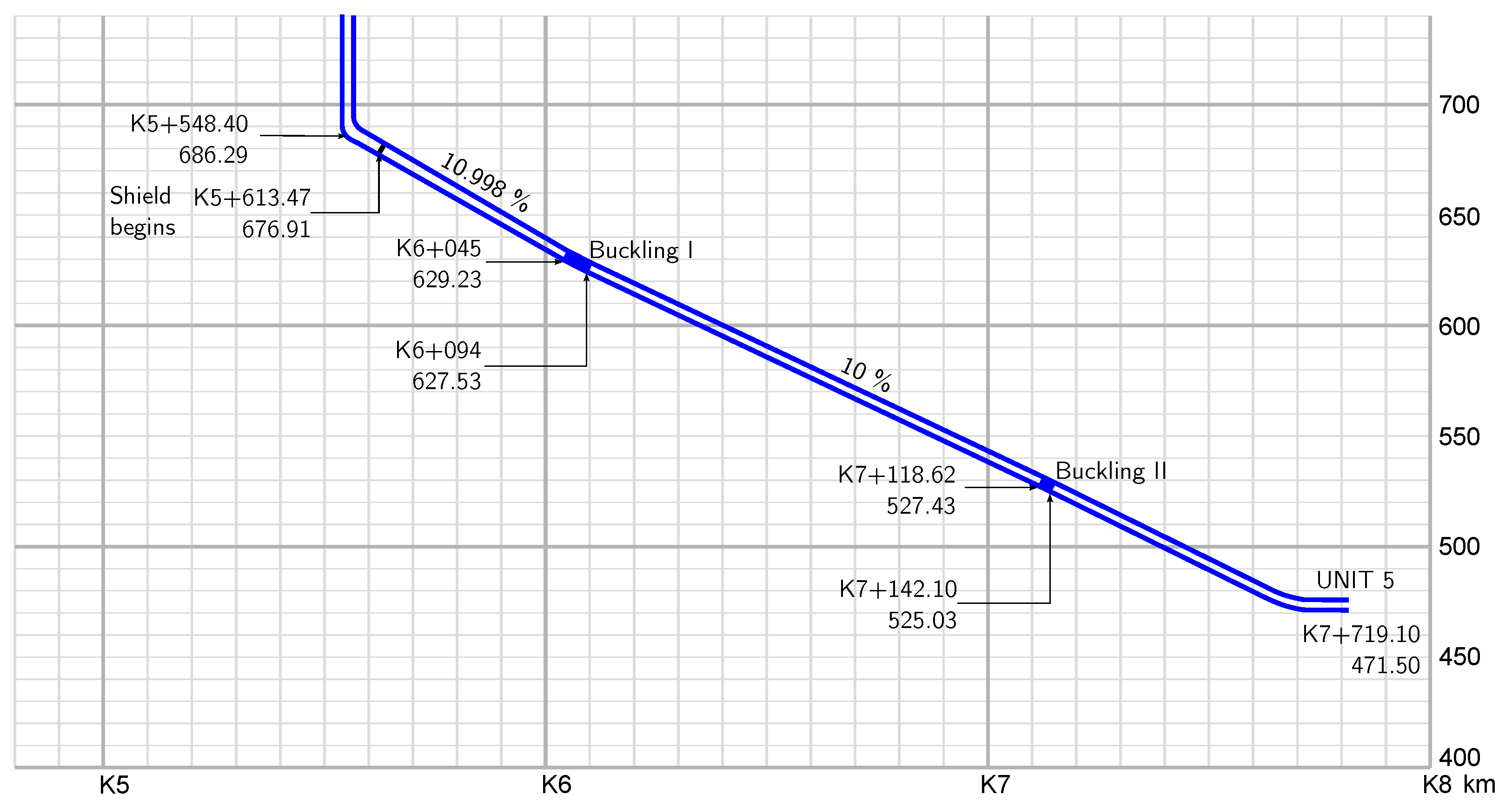
2.1. Chivor Hydropower Project and Buckling Events

Ensuring sustainable energy for Colombia requires not only the development of new renewable power generation projects, but adapting and renovating existing hydropower facilities. Several large-scale hydropower projects within the country are in the ageing stage, and several companies are facing challenges to keep them operating to support the increasing energy demand within the region. The Chivor Hydropower Plant, located at Santa María, Boyacá (160 km northeast from Bogotá, Figure 1) is owned by AES Corporation and has an installed capacity of 1000 MW (eight 125-MW Pelton turbines). Chivor entered into service in 1977, with an initial life expectancy of 50 years (roughly until 2025), and the company has been developing projects to extend the operation for 50 more years [50,51]. Some elements have been affected by erosion and corrosion, including the lining of headrace tunnels that conduct water from the reservoir to the powerhouse, which also withstand the suppression effect (hydraulic shock) caused by load rejections in the generation units.
The Chivor Power Plant conduction system consists of two headrace tunnels (Chivor I: 7.985 km and Chivor II: 8.009 km) with a total length of 16 km, that operate under a maximum flow of approximately 160 m 3 /s. Chivor’s II shielded area is located at the lower tunnel, which is 2.07 km long, and consists of a cylindrical steel pipe with an internal diameter of 3.9 m, reinforced with pre-stressed bands of the same material on the outer perimeter, see Figure 2. During Chivor’s construction stage, two events occurred and directly affected the installed lining of Chivor II, which have been called Buckling I and II, Figure 3. According to the project’s records, the buckling occurred as a consequence of the injection pressure during construction in the first case, and later due to the action of an overpressure coming from a leak from Chivor I, creating pressure and thrust on this section of Chivor II. The Buckling I section (K6 + 045–K6 + 094) was corrected in 1981, with the installation of a steel pipe with a diameter of 3.1 m, with conical transitions at its ends at 3.9 m. In December 2019 it was scheduled a Chivor II dewatering, in order to remove weak material around Buckling II and to install a new pipe.

2.2. Chivor II Headrace Tunnel Assessment

Since the year 2000, AES has been assessing the state of the pipelines and the Buckling II zone in order to ensure the stability of the conduction tunnels. In the year 2000 Chivor II was emptied during a scheduled maintenance, and all butterfly valves were replaced or repaired, the gravel trap of the tunnel was cleaned, and a new steel pipe was installed as a liner in a 19.8-m section within a zone surrounded by limestone. The headrace tunnel was emptied again in 2014 and the intervention was centered on replacing relief valves and measuring the thickness of shield plates using ultrasound, which evidenced a 50% loss in thickness for 24 of the plates; hence, A36-steel 6-mm sacrificial plates were installed on plates 1 to 53, equivalent to 329.9 m 2 . By 2015, thickness-loss evaluation continued and plates 54 to 129 were replaced; this is equivalent to 602.8 m 2 of sacrificial material to keep the tunnel operating. In the same year, an Insulated Component Test (InCoTest) [56] that uses the pulse eddy current method, and that is considered one of the most reliable corrosion detection method, was performed to eight of the plates allowing determining the percentage of volumetric material loss in the inspection area (6-inch grids in this case).

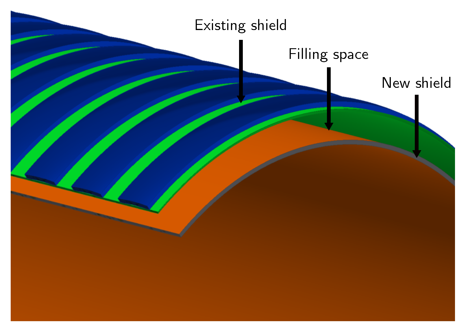
2.3. Lining Renovation Alternatives

AES Corporation has been working towards renovating the Chivor Hydropower Project, and executed the Chivor’s Life Extension Project in order to extend the life expectancy of the power plant for at least 50 more years [50]; such work started from sediment transport studies and lead to build a new intake system based on different design alternatives [51]. This time, the renovation for the lined section of a headrace tunnel represented a challenging design process, due to the conclusions given by the condition assessment, and because the construction planning has to be done precisely in order to keep the hydropower project operating.
The reference parameter for the design alternatives was the optimal diameter of the new pipeline’s lining. This parameter was selected based on the cost analysis between investment and energy production under a defined production scheme. The restrictions for the selection process were the diameters of the sections at Buckling I and Buckling II (see Figure 3), and the diameter of the existing lining of the headrace tunnel ϕ = 3.9 m. For energy production, the flow parameters inside the tunnel and the conditions of the reservoir were evaluated. The current flow velocity in the tunnel is 6.7 m/s, by reducing the diameter of the tunnel the flow velocity increases, generating greater global losses and abrasive phenomena that will affect the useful life of the tunnel to a greater extent. Therefore, the definition of the new internal diameter of the tunnel lining was limited to the minimum possible increase in flow velocity.
Four different design alternatives were established for the lining in order to renovate the headrace tunnel. Such alternatives were evaluated by a committee, as stablished by AES, that was conformed by national and international experts based on the following criteria: the pre-design process of the alternative, analysis of the materials to be used, constructability, construction costs, and deadlines. The pre-design process allowed evaluating material quantities and their characteristics, mechanical properties for manufacturing, supply and installation options inside the headrace tunnel Chivor II [23]. The constructability criterion permitted to identify risks associated with the execution of the renovation project [9]. Finally, a comparison between prices of materials prices and execution times was done by analyzing the market and similar renovation projects [17].

2.4. Design Alternative 1: Self-Supporting Lining with Complete Plates

Alternative number 1 considered a self-supporting pipe with a diameter of 3.6 m, which would be installed using full-circumference plates in sections between 3–6 m in length, Figure 4. This alternative would need the construction of an access gallery and an assembly chamber for the installation of complete plates that would require only circumferential welding, Figure 2. To install such plates, Buckling I would need to be demolished, and a provisional lining that allows passing the plates upstream would be required, to later reestablish the Buckling 1 area with a 3.6 m pipe. For the Buckling II zone, complete plates are impossible to install because of this section’s diameter, hence, the diameter of the lining in this section would be 3.4 m. In the assembly chamber or cavern, the sections coming from the access gallery would be received and aligned with the axis of the existing pipe. Inside the cavern, the pipe must be cut, replacing the eliminated section with a self-supporting section to allow the system to be reassembled once the plant needs to resume its normal operation. The main advantages of this option are the reduction of construction times due to the simplification of the installation tasks inside the existing lining, and the reduction of welding work by applying only circumferential welds.

2.5. Design Alternative 2: Self-Supporting Lining with Multi-Section Plates

The second alternative for the lining renovation considered a self-supporting pipe, which would be divided in section plates of 1 m in length, Figure 5. This alternative would use the access gallery 3A, Figure 2, which has a diameter of 2.55 m, to enter the sections in order to be welded inside. Unlike Alternative 1, the construction of the lining would require longitudinal welded joints in both sides of the plate, which increases the risk of defects along the direction of the joint. In this type of joint, the circumferential stresses are perpendicular to the direction of microcracks, which increases the probability of their growth [21,31]; opposite to this situation, in circumferential joints a microcrack that is parallel to the joint direction has no grow possibility since the greatest stress occurs also in a direction that is parallel to the joint. Therefore, complete longitudinal welded joints with full penetration from both sides of the plate would be required allowing appropriate inspection; this means that the design process had to consider a joint efficiency equal to one [23]. Backing would be used only in circumferential joints, helping not only to back root welding but facilitating the alignment of the sections. When plate sections are considered, the rehabilitation upstream Buckling I and downstream Buckling II presents no major restrictions since this alternative does not require demolishing Buckling I, and a 3.6-m diameter is considered downstream Buckling II.

2.6. Design Alternative 3: Carbon-Fiber Internal Structural Coating

Alternative number 3 was considered due to access and logistics restrictions that appear in a more traditional structural rehabilitation process. In this case, carbon fiber would be considered either as a structural reinforcement of the existing lining or as a stand-alone system that acts in conjunction with the existing pipe, provided that the existing lining was structurally viable for this purpose, Figure 6. Latest interventions inside Chivor II headrace tunnel have shown no deficiencies or structural problems, however, it was assumed that the existing lining had not exceeded the yield stress; load and deformation tests would be required to verify such hypothesis. Should this condition can not be verified, this alternative would not be considered feasible. Limitations for this renovation alternative are the cost, the installation time, and the fact that after the carbon-fiber reinforcement would be installed, the existing steel lining would not be accessible anymore.

2.7. Design Alternative 4: Internal Structural Coating with Steel and Carbon-Fiber

Alternative 4 considered a self-supporting lining and that the existing steel structure and the structural carbon-fiber reinforcement would work together, due to the fact that carbon fiber layers would structurally reinforce the tunnel, Figure 7. The carbon fiber reinforcement has the objective of lowering the requirement on steel plates since thickness could be reduced and more commercial non-high-strength steels could be chosen in order to decrease costs and increase weldability properties. The detailed design of this alternative would require analyzing the interaction between the carbon fiber and the steel, using reduced models and physical tests. It has been estimated that 10 carbon-fiber-reinforced-plastic (CFRP) layers would be required to reduce the amount of steel by approximately 75%, yielding to steel sheets with an estimated thickness of 25 mm.

2.8. Detailed Design Excerpts

With several alternatives generated in the conceptual/basic design stages for the renovation project, different analyses were performed, including financial and technical reviews and probabilistic modeling and risk profile. The technical-financial review contemplated the study of the background information available to date including the existing studies prepared specifically for the Project. In particular, the following information packages were reviewed: geological and geotechnical Information [34,35], verification of the state of the pipes [56], review of engineering studies [23,36], analysis of the project design [23,25,28], costs of civil and hydromechanical works [11], and construction schedule [54,57]. The probabilistic modelling and determination of the Project’s risk profile considered the following key risk factors [4,11]: short-term failure of the currently installed penstock pipe, energy generation loss due to penstock failure and leakage, underground works budget and schedule overruns due to unfavorable rock class distribution, and long project schedule overrun due to extended welding times. The probabilistic distribution of the total cost and construction schedule was used in decision making with respect to project implementation of Design Alternative 2.

2.8.1. Design and Construction Considerations

After the selection of the alternative for the construction of the headrace tunnel renovation, the following design considerations were defined by the project team:
  • The pipe must withstand 100% of the internal-pressure-associated loads, without contributions from the concrete or the rock behind the existing lining.
  • The pipe must withstand 100% of the external loads due to the water table when the tunnel is empty (no water inside). External stiffening rings must be used where needed to increase rigidity.
  • The existing lining will not be used to increase the resistance of the new pipe.
  • The pipe will be embedded in concrete filler.
  • Installation of expansion joints will not be considered.
  • Active loads over the structure will not be considered (e.g. wind, snow, etc.)
  • Added thickness for corrosion phenomena will be 2 mm.
  • Joint efficiency will be defined as 100% for complete longitudinal welded joints with full penetration from both sides of the plate, with 100% visual and UT examination.
  • Circumferential joints will be made inside the pipe once the plates have been aligned. For circumferential welds in the field, the use of a backing plate is expected since there is no access from the outside.
  • The gap between the new pipe and the existing one will be considered to be 0.8 mm, this is 0.0045% R (lining radius). This value was selected within the range indicated by CECT [58] (Appendix IIE, 6.2.5.1) for a highly-confined lining (good quality rock which in this case is represented by the existing lining).
The renovation project imposes design limitations that challenged the Construction Management Team (CMT) with respect to the material to be used. The space between the existing and the new lining incorporated additional requirements to those normally established for a steel-high-pressure lining such as the yield strength of the material, which needs to be used to compute thicknesses that do not result redundant. In this case, special requirements were imposed by the construction process, since it is required that welds are to be done with access from one side of the pipe only, under adverse temperature and humidity conditions. Additionally, not only these technical requirements were considered for the material selection, but also prices and market availability of steel sheets and welding consumables were taken into account for this matter [59,60]. Table 1 contains a description of the material to be used for the renovated lining.
With this selection to build the new lining, the CMT defined the following security factors for design and construction stages Power Resources Office and Technical Service Center [23], CECT [58], ASCE [61]:
  • Internal pressure loads, considering maximum operating pressure (water hammer), and that the pipe is embedded within concrete. Safety factor = 1.5.
  • External pressure loads that can cause collapse due to instability, considering that the pipe is embedded within concrete. Safety factor = 1.6.
  • Safety coefficient when applying pouring concrete = 1.5.
  • Safety coefficient during contact injections = 2.
  • Safety factor for material handling and assembly processes = 1.2.

2.8.2. Design Calculations

Structural computations for the renovated lining required first the determination of the internal and external pressure loads in the headrace tunnel. Figure 8 shows the internal pipe pressure (in MPa) for the structural design and the pipe profile in meters above the sea level (m.a.s.l) against the distance (km) for the shielded section of Chivor II headrace tunnel.
For loads associated to the external pressure, the water table’s geological profile was used to define discrete-pressure intervals. Figure 9 shows the external pipe—discrete pressure (in MPa), the pipe profile, and the water table’s geological profile (m.a.s.l) against the distance (km). The minimal value for the external pressure was set by AES to 1.8 MPa, even for pressures generated by the water table that are under this value.
The structural calculation considered the following main steps: determining the thicknesses for different sections of the lining, defining requirements for stiffening rings, and computing distances between stiffening rings and their geometries for different sections of the headrace tunnel. The following load cases were considered for the structural design of the lining: operative tunnel under the action of internal pressure loads considering maximum operating value (water hammer) plus ±10 °C temperature variation, and empty tunnel under the action of external pressure loads given by the water table of the rock mass. The detailed design for these cases required: (i) computations for the pipe to be transported and handled (minimum wall thickness for handling), (ii) straight pipe sections under internal pressure and temperature effects, (iii) straight pipe sections under external pressure loads, (iv) transitions considering minimal wall thickness, and (v) transitions under the effect of external pressure loads. In this work, we show excerpts of the process for the first two cases (i and ii), using equations provided in specialized literature Power Resources Office and Technical Service Center [23], CECT [58], ASCE [61].
Minimum wall thickness for handling. The computation of this thickness was done under instructions provided in the ASCE Manuals and Reports [61], which indicates
t m i n = D 288 for D > 1350 mm .
Substituting D = 3600 mm yields t m i n = 12.5 mm. Because of commercial availability, this thickness is approximated to 12.7 mm, i.e., 1/2 .
Internal pressure and temperature effects. The computation of this part was done under instructions provided in the ASCE Manuals and Reports [61]. First, circumferential stresses are computed for different sections of the headrace tunnel by:
σ C = P ( D i + t + e ) 2 ( t e ) E j ,
where, σ C is the circumferential stress, P is the internal pressure, D i is the theoretical internal diameter, t is the wall thickness, e = 2 mm additional thickness defined to consider corrosion effects, and E j = 1 is the joint efficiency. Then, longitudinal stresses were computed considering the combination of the Poisson effect σ L 1 and thermal variation σ L 2 as follows:
σ L = σ L 1 + σ L 2 .
where:
σ L 1 = ν S c , and σ L 2 = E α Δ T ,
with ν = 0.3 the Poisson’s modulus for steel, E the Young’s modulus (Table 1), α the coefficient of thermal expansion (Table 1), and Δ T = 10 C the assumed temperature variation for this hydropower installation. Once all stresses were computed, the von Mises stress was calculated and compared to the admissible stress given by the security factors that were defined for the development of the new lining, using appropriate standards [25]; for a plane-stress condition the von Mises stress is given in terms for the circumferential and longitudinal stresses as follows
σ v = σ C 2 + σ L 2 σ C σ L .
For internal pressure loads, the admissible stress is given by σ a d m = 690/1.5 = 460 MPa. Table 2 contains the computations for two different sectors of the pipeline, considering tension and compression thermal effect loads for cases with positive and negative variations in temperature. In both sections, a security factor greater than 1.5 was obtained, verifying thickness selection.
External pressure, stiffening rings and transitions. For these calculations, thicknesses that were obtained to withstand the internal pressure needed to be verified for external pressure associated loads. As it was expected, the verification of the security factors was not approved in the case of requiring to build the pipe without the use of stiffener rings, hence, another iteration to solve the equations that allow performing structural calculations for external pressure loads, as described in [61], was carried out by the CMT. After the need of stiffening rings was evidenced, the CMT performed calculations that lead to security factors higher than the ones defined in Section 2.8.1 for both the pipe sections between rings and for the stiffening rings using [38,61]. Conical transitions to connect the renovated pipe with sections of different diameters were designed as defined by ASME [62].

3. Results

3.1. Chivor II Headrace Tunnel Assessment

Regarding the aforementioned Insulated Component Test (InCoTest) [56], Table 3 shows a comparison between the thickness data measured in a two-year period. The results of this test confirmed data obtained in 2014 using ultrasound testing (UT), validating its use for further structural analyses.
Reasonable correlations were obtained between the sets of data, and some differences were expected because of the difference in area, since the InCoTest yields the average over a 6-in by 6-in area, and the UT is a measure at one discrete point of the plate. For instance, it can be seen that for plate 115, the minimum measured thickness is 71% of the measured UT value, which indicates a critical loss of 29% in thickness for that plate. The condition of a 2-km stretch of the Chivor II headrace tunnel (between K5 + 610 and K7 + 682) was assessed in 2015. The study considered an internal inspection, reviewing design and operating documentation, and hydraulic and structural analyses in order to estimate the residual useful life (RUL), which yielded the following conclusions:
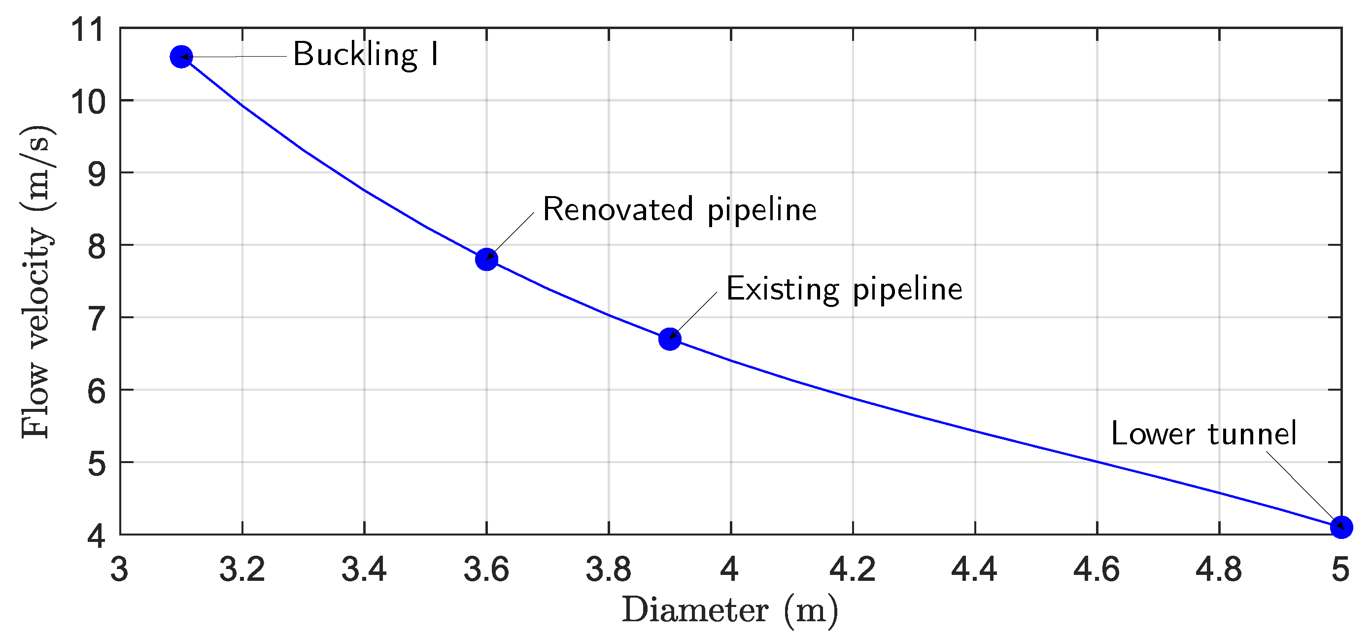
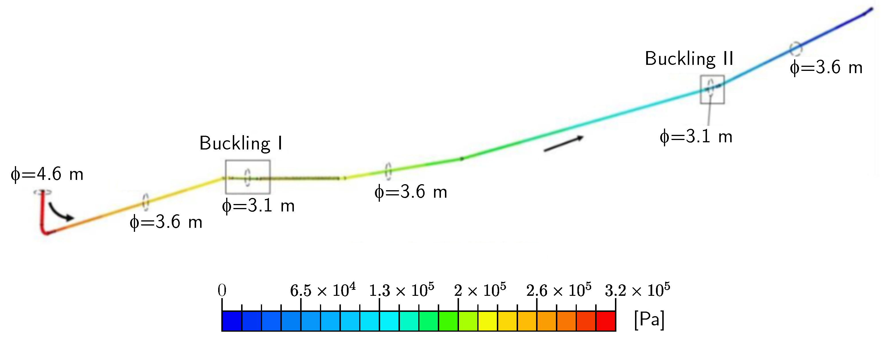
  • Internal inspections showed that pipe lining wall deterioration was concentrated in the pipeline invert (base interior level of the pipe). Significant wall loss was observed and measured in the upstream section of the pipeline, between the vertical shaft and Buckling I, where the lining showed a minimum average wall thickness of 54%, while the remaining portions of the pipeline exhibited minimal wall loss. The calculated steady-state flow through the pipeline (92.2 m 3 /s), with all the four Chivor II’s turbines in operation, yielded the following velocities at four sections of the lining that have different diameters: 7.3 m/s @ ϕ = 3.9 m; 12.2 m/s @ ϕ = 3.1 m; 13 m/s @ ϕ = 1.5 m in branches 5–8; and 7.6 m/s @ ϕ = 0.8 m in needle valve inlet piping. This allowed concluding that the lining deterioration was linked to excessive velocities.
  • Evaluation of the original design (with no wall deterioration) using Finite Element Analysis (FEA) [29] showed that 90% of the pipe’s sections exceeded the allowable design stress, and 36% of the pipe’s sections were at the yield limit. When deterioration was considered during the 2015 assessment, FEA results showed that 59% pipe sections had exceeded the yield limit and other 37% of the pipe sections were within 10% of the yield limit. Statistical modeling under such conditions showed that more than 50% of the plates had a RUL less than 20 years; this modeling was considered valid where the pipe had not reached the yield limit and where the only failure mode considered for the pipe was wall deterioration.
  • The original protective coating of the pipeline, made up of a zinc-rich polymeric film and a tarred finish, was also assessed, and the study showed that the coating failed 100% in the 04:00 to 08:00 time zone of the pipeline. Small traces of coating were still found within some areas of the 08:00 to 03:00 time zone of the pipe. The coating reached its useful life and showed a general deterioration process, mainly due to cracking and pore formation. The main process that has been affecting the coating is the abrasive action of the fluid, which contains a high concentration of silica, organic and clay-based material. Once the coating has failed in a section of the lining, a differential aeration corrosion phenomenon occurs as a result of the formation of crusts within a low-oxygen area. The area under the crust acts as an anode and the surroundings as a cathode, generating a highly accelerated corrosion process.

3.2. Diameter of the New Pipeline

In order to obtain a balance among cost, energy production, and construction conditions, a design diameter ϕ = 3.6 m was selected for the renovation project. This value allows decreasing loses and building smoother transitions to sections with smaller diameters; in this case, water velocity will be 7.85 m/s, Figure 10. Regarding abrasive phenomena caused by water conditions of the reservoir, an appropriate coating needs to be selected for the construction process in order to protect the new lining’s surface. Figure 11 shows the distribution of pressure loss within the headrace tunnel for the new 3.6-m diameter. The model was obtained for the section between the vertical shaft and the bifurcation zone for the turbines, using 3D SimScale®; a total loss of 33.15 m was obtained. The greatest turbulence occurs in the area near the transition to the lower tunnel, affecting the lining’s surface due to the sediment load. These sediments generate a greater affectation with respect to laminar-flow zones.

4. Discussion

The design for the renovation of Chivor II headrace tunnel was done based on the condition assessment of the existing liner with a set of design requirements that established the need for a self-supporting lining capable of providing the appropriate structural resistance, using appropriate hydraulic engineering standards. The material selected to build the new lining incorporates high-resistance technology, which allows not only optimizing the thicknesses, but facilitating welding the joints that otherwise would require stress-relief processes; this decreases the probability of reducing the initial resistance of the steel due to welding. Additionally, the installation of the new self-supporting lining with an internal diameter ϕ = 3.6 m will facilitate the connection to the repaired buckling sections that are of smaller dimensions. The annular space between the existing and the new lining will be filled with a contact grouting that will help with the radial transmission of pressure stresses from the new internal lining to the outside. Finally, the transitions that were designed can be used at any section of the pipe for cases at which the renovations need to be suspended in an eventual call from the national system to face an energy contingency.
During the first design stage, the existing lining was analyzed in order to consider its contribution to the structural resistance of the renovated lining, however, since a huge part of the material has reached and/or exceeded the elastic resistance this option was discarded. Therefore, the alternative of using a new self-supporting pipe was considered as the only option, which significantly reduced the risks of the project, limiting the analysis matrix to alternatives that can be carried out considering their own structural resistance, without contributions from the existing pipe and the rock. These options eliminated the need to assess geological components during the design stage, and increased the Stakeholder’s confidence for financing and insuring the asset. Additionally, the RUL and future behavior of the new pipe can be estimated without considering variables that are unknown or difficult to determine within such a large-scale renovation process.
The renovation of existing hydropower infrastructure requires comprehensive studies and design processes. This case report has shown excerpts of the design process for the new self-supporting liner that will be used to renovate the Chivor II headrace tunnel at Chivor Hydropower Project, but several questions and uncertainties appeared during the presented design process, and they need to be addressed before the construction process begins. Because of the geometry of the selected alternative, the construction will require a lot of welding work, but no information or calculations have been provided regarding welding times, hence, a detailed analysis of the construction time needs to be carried out. Additionally, after selecting the alternative for the renovation of the liner, including materials and appropriate dimensions, the following issues must be considered by the Construction Management Team in the next stage: welding times, construction costs, construction schedule, logistic processes, risk analysis, among others. Logistics represents a major uncertainty for the project execution, since several work fronts shall be needed; for instance, all the equipment and machinery required for the construction of the new liner. Therefore, a comprehensive investigation must be carried out to determine a suitable construction procedure.
This report represents an example for managers and practitioners of large-scale hydraulic engineering projects, and contributes to the regional development of sustainable energy systems. The life extension of the Chivor Hydropower Project, that covers 6% of Colombia’s energy demand, will help ensuring the reliability of the Colombian supply system [50] by 50 more years, within a country whose demand grew near to 3% during the last decade, and where the installed capacity of the National Interconnection System is about 16 + GW [63]. Although the mix is being diversified with new generation strategies, the Colombian energy market requires guaranteeing the operation of existing plants such as Chivor, because hydroelectric production represents nowadays 70% in the mix, while 30% is provided from mostly thermal power plants and new renewable installations that have been growing together with hydropower infrastructure that has also been growing and being renovated within the American continent [10,48].

5. Conclusions

This paper addressed the design of a self-supporting lining for the renovation of a headrace tunnel in order to extend the operating life of the Chivor Hydropower Project, located in Colombia. Studies performed on buckling events that affected the headrace tunnel and the condition assessment were used to choose among four different design alternatives to renovate this important part of the plant’s infrastructure. The selected alternative considers a self-supporting lining capable of providing the appropriate structural resistance for different load conditions: material handling, internal pressure loads, temperature variation, and external pressure loads exerted by the water table over the empty tunnel. The detailed design allowed obtaining the minimum wall thickness for handling, and the dimensions of straight pipe sections, transitions, and external stiffening rings. The material selected to build the new lining incorporates high-resistance technology, which allows not only reducing the material to be used, but facilitates welding processes that must be carried out during the construction phase. Although the excerpts of the design process shown in this work included determining the material and appropriate dimensions, several issues must be addressed in a comprehensive investigation for the next stage, including but not limited to: welding times, construction costs, construction schedule, logistic processes, and risk analysis.
This projects aims at extending the life of an existing 1000-MW (6% of Colombia’s energy demand) powerplant for 50 more years, contributing to the sustainable energy supply for the future as stated in the 7th SDG: “Ensure access to affordable, reliable, sustainable and modern energy for all”. The successful implementation of a hydropower plant life-extension project needs to include analyzing and adapting the reservoirs, an detailed analysis of the status of all components of the plant, including: intakes, headrace tunnels (as in this work), electrical equipment, among others. This can be successfully implemented for large-scale hydropower projects by using Engineering–Procurement–Construction (EPC), as described by Liu et al. [57], since this model has been increasingly adopted for improving hydropower design projects delivery efficiency.

Author Contributions

Conceptualization, D.A.d.R., J.A.C., J.T.M., C.N.-L., R.E.V. and A.E.-A.; methodology, D.A.d.R., J.A.C., J.T.M.; validation, D.A.d.R., J.A.C., J.T.M., C.N.-L., R.E.V. and A.E.-A.; formal analysis, C.N.-L., R.E.V. and A.E.-A.; investigation, D.A.d.R., J.A.C., J.T.M., N.C.P.-R., C.N.-L., R.E.V. and A.E.-A.; writing—original draft preparation, C.N.-L., R.E.V. and A.E.-A.; writing—review and editing, C.N.-L., R.E.V. and A.E.-A.; supervision, N.C.P.-R., C.N.-L., R.E.V. and A.E.-A. All authors have read and agreed to the published version of the manuscript.

Funding

This work was developed with the funding of AES Colombia and is partially registered in the Colombian Ministry of Science, Technology, and Innovation (Minciencias) as a technological development project “Desarrollo de alternativas constructivas para la instalación de un blindaje autoportante dentro de la conducción de Chivor II. Fase I: diseño y preparación”, as allowed by the National Tax Benefits Council, Project 93719.

Institutional Review Board Statement

Not applicable.

Informed Consent Statement

Not applicable.

Data Availability Statement

The data presented in this study are available on request from the corresponding author.

Acknowledgments

The authors would like to thank AES Colombia and all the teams that have participated within Chivor II headrace tunnel renovation Project.

Conflicts of Interest

D.A.d.R., J.A.C., J.T.M., and N.C.P.R. work for AES Colombia and have lead Chivor II headrace tunnel renovation Project.

References

  1. United Nations. World Population Prospects 2022: Summary of Results; Technical Report DESA/POP/2022/No. 3; United Nations, Department of Economic and Social Affairs, Population Division: New York, NY, USA, 2022; Available online: https://www.un.org/development/desa/pd/content/World-Population-Prospects-2022 (accessed on 15 November 2022).
  2. IEA. World Energy Outlook 2021, Technical Report WEO-2021; International Energy Agency: Paris, France, 2021. Available online: https://www.iea.org/reports/world-energy-outlook-2021(accessed on 15 November 2022).
  3. IEA. World Energy Investment 2022, Technical Report WEI-2022; International Energy Agency: Paris, France, 2022. Available online: https://www.iea.org/reports/world-energy-investment-2022(accessed on 15 November 2022).
  4. Ioannou, A.; Angus, A.; Brennan, F. Risk-based methods for sustainable energy system planning: A review. Renew. Sustain. Energy Rev. 2017, 74, 602–615. [Google Scholar] [CrossRef]
  5. IEA; IRENA; UNSD; World Bank; WHO. Tracking SDG 7: The Energy Progress Report, Technical Report; World Bank: Washington, DC, USA, 2022. Available online: https://trackingsdg7.esmap.org/(accessed on 15 November 2022).
  6. United Nations. The Sustainable Development Goals Report 2022, Technical Report; United Nations Publications: New York, NY, USA, 2022. Available online: https://unstats.un.org/sdgs/report/2022/(accessed on 15 November 2022).
  7. World Water Council. Analysis of the 3rd World Water Forum, Technical Report; World Water Council: Marseille, France, 2003. Available online: https://digitallibrary.un.org/record/3892704?ln=en(accessed on 15 November 2022).
  8. Kondolf, M.; Yi, J. Dam Renovation to Prolong Reservoir Life and Mitigate Dam Impacts. Water 2022, 14, 1464. [Google Scholar] [CrossRef]
  9. Kumar, K.; Saini, R. A review on operation and maintenance of hydropower plants. Sustain. Energy Technol. Assess. 2022, 49, 101704. [Google Scholar] [CrossRef]
  10. IHA. 2022 Hydropower Status Report: Sector Trends and Insights, Technical Report; International Hydropower Association (IHA): London, UK, 2022. Available online: https://www.hydropower.org/publications/2022-hydropower-status-report(accessed on 15 November 2022).
  11. Shaktawat, A.; Vadhera, S. Risk management of hydropower projects for sustainable development: A review. Environ. Dev. Sustain. 2020, in press. [CrossRef]
  12. Kougias, I.; Aggidis, G.; Avellan, F.; Deniz, S.; Lundin, U.; Moro, A.; Muntean, S.; Novara, D.; Pérez-Díaz, J.I.; Quaranta, E.; et al. Analysis of emerging technologies in the hydropower sector. Renew. Sustain. Energy Rev. 2019, 113, 109257. [Google Scholar] [CrossRef]
  13. Schleiss, A.J.; Manso, P.A. Design of pressure relief valves for protection of steel-lined pressure shafts and tunnels against buckling during emptying. Rock Mech. Rock Eng. 2012, 45, 11–20. [Google Scholar] [CrossRef] [Green Version]
  14. Tun, S.W.; Singal, S.K. Management of Hydropower Tunnels to Prevent Collapse and Remedial Measures. Hydro Nepal J. Water, Energy Environ. 2016, 19, 31–37. [Google Scholar] [CrossRef]
  15. Panthi, K.K.; Basnet, C.B. Review on the Major Failure Cases of Unlined Pressure Shafts/Tunnels of Norwegian Hydropower Projects. Hydro Nepal J. Water Energy Environ. 2016, 18, 6–15. [Google Scholar] [CrossRef] [Green Version]
  16. Kawamura, F.; Miura, M.; Ebara, R.; Yanase, K. Material strength of long-term used penstock of a hydroelectric power plant. Case Stud. Struct. Eng. 2016, 6, 103–114. [Google Scholar] [CrossRef] [Green Version]
  17. Bonapace, P.; Hammer, A.; Maldet, R.; Schüller, O. The renewal of the pressure shaft for the Kaunertal high-head hydropower plant in Austria. Steel Constr. 2016, 6, 257–264. [Google Scholar] [CrossRef]
  18. Yang, F.; Zhang, C.; Zhou, H.; Liu, N.; Zhang, Y.; Azhar, M.U.; Dai, F. The long-term safety of a deeply buried soft rock tunnel lining under inside-to-outside seepage conditions. Tunn. Undergr. Space Technol. 2017, 67, 132–146. [Google Scholar] [CrossRef]
  19. Xiao, M.; Zhao, C. Stability Analysis of Steel Lining at Pressure Diversion Tunnel Collapse Zone during Operating Period. Math. Probl. Eng. 2017, 2017. [Google Scholar] [CrossRef] [Green Version]
  20. Sheikh, K.A.; Saif, A. Steel Fibre-Reinforced Shotcrete as an alternative to conventional concrete tunnel lining: A case study of Gulpur Hydropower Project. Geomech. Geoengin. 2019, 15, 252–262. [Google Scholar] [CrossRef]
  21. Liu, T.J.; Chen, S.W.; Lin, P.Q.; Liu, H.Y. Failure mechanism and strengthening effect of shield tunnel lining reinforced by steel plates with corbels. Eur. J. Environ. Civ. Eng. 2020, 26, 1603–1621. [Google Scholar] [CrossRef]
  22. Gabl, R.; Wippersberger, M.; Seibl, J.; Kröner, C.; Gems, B. Submerged Wall Instead of a Penstock Shutoff Valve—Alternative Protection as Part of a Refurbishment. Water 2021, 13, 2247. [Google Scholar] [CrossRef]
  23. Power Resources Office and Technical Service Center. Facilities Instructions, Standards, and Techniques—Inspection of Steel Penstocks and Pressure Conduits; Technical Report FIST 2-8; United States Department of the Interior, Bureau of Reclamation: Denver, CO, USA, 2022. Available online: https://www.usbr.gov/power/data/fist_pub.html (accessed on 26 October 2022).
  24. Omara, A.M.; Guice, L.K.; Straughan, W.T.; Akl, F.A. Buckling models of thin circular pipes encased in rigid cavity. J. Eng. Mech. 1997, 123, 1294–1301. [Google Scholar] [CrossRef]
  25. Jian-Guo, H.; Xu-Wen, A.; Ying-Min, H. Comments on design methods of penstocks. J. Press. Vessel Technol. Trans. ASME 2004, 126, 391–398. [Google Scholar] [CrossRef]
  26. Bobet, A.; Nam, S. Stresses around pressure tunnels with semi-permeable liners. Rock Mech. Rock Eng. 2007, 40, 287–315. [Google Scholar] [CrossRef]
  27. Vasilikis, D.; Karamanos, S.A. Stability of confined thin-walled steel cylinders under external pressure. Int. J. Mech. Sci. 2009, 51, 21–32. [Google Scholar] [CrossRef]
  28. Hachem, F.; Schleiss, A.J. The design of steel-lined pressure tunnels and shafts. Int. J. Hydropower Dams 2009, 16, 2009. Available online: https://www.hydropower-dams.com/articles/the-design-of-steel-lined-pressure-tunnels-and-shafts/ (accessed on 15 November 2022).
  29. Valdeolivas, J.L.; Mosquera, J.C. A full 3D finite element model for buckling analysis of stiffened steel liners in hydroelectric pressure tunnels. J. Press. Vessel Technol. Trans. ASME 2013, 135, 1–9. [Google Scholar] [CrossRef]
  30. Lin, P.; Zhou, Y.; Liu, H.; Wang, C. Reinforcement design and stability analysis for large-span tailrace bifurcated tunnels with irregular geometry. Tunn. Undergr. Space Technol. 2013, 38, 189–204. [Google Scholar] [CrossRef]
  31. Cerjak, H.; Enzinger, N.; Pudar, M. Development, experiences and qualification of steel grades for hydro power conduits. Steel Constr. 2013, 6, 265–270. [Google Scholar] [CrossRef]
  32. Simanjuntak, T.D.; Marence, M.; Mynett, A.E.; Schleiss, A.J. Pressure tunnels in non-uniform in situ stress conditions. Tunn. Undergr. Space Technol. 2014, 42, 227–236. [Google Scholar] [CrossRef]
  33. Li, X.; Li, Y. Research on risk assessment system for water inrush in the karst tunnel construction based on GIS: Case study on the diversion tunnel groups of the jinping II hydropower station. Tunn. Undergr. Space Technol. 2014, 40, 182–191. [Google Scholar] [CrossRef]
  34. Zhang, C.; Liu, N.; Chu, W. Key technologies and risk management of deep tunnel construction at Jinping II hydropower station. J. Rock Mech. Geotech. Eng. 2016, 8, 499–512. [Google Scholar] [CrossRef] [Green Version]
  35. Pachoud, A.J.; Schleiss, A.J. Stresses and displacements in steel-lined pressure tunnels and shafts in anisotropic rock under quasi-static internal water pressure. Rock Mech. Rock Eng. 2016, 49, 1263–1287. [Google Scholar] [CrossRef]
  36. Bobet, A.; Yu, H. Full stress and displacement fields for steel-lined deep pressure tunnels in transversely anisotropic rock. Tunn. Undergr. Space Technol. 2016, 56, 125–135. [Google Scholar] [CrossRef] [Green Version]
  37. Palmström, A.; Broch, E. The design of unlined hydropower tunnels and shafts: 100 years of Norwegian experience. Int. J. Hydropower Dams 2017, 24, 1–9. Available online: https://www.hydropower-dams.com/articles/the-design-of-unlined-hydropower-tunnels-and-shafts-100-years-of-norwegian-experience/ (accessed on 26 October 2022).
  38. Kravanja, S. Optimization of a Steel Penstock With Stiffener Rings. Elektron. časopis Građevinskog Fak. Osijek 2018, 9, 64–73. [Google Scholar] [CrossRef]
  39. Wang, Y.; Cao, R.; Pi, J.; Jiang, L.; Zhao, Y. Mechanical properties and analytic solutions of prestressed linings with un-bonded annular anchors under internal water loading. Tunn. Undergr. Space Technol. 2020, 97, 103244. [Google Scholar] [CrossRef]
  40. Haddouch, M.; Hajjout, I.; Boudi, E.M. Sizing optimization of exposed steel penstocks supported by ring girders using the combined ANN-GA technique. Structures 2020, 24, 705–716. [Google Scholar] [CrossRef]
  41. Ma, Z.; Shi, C.Z.; Wu, H.G. Numerical cracking analysis of steel-lined reinforced concrete penstock based on cohesive crack model. Structures 2021, 34, 4694–4703. [Google Scholar] [CrossRef]
  42. Diaz-Arellano, P.; Jaque-Castillo, E.; Ojeda, C.G. Presión Hídrica en Ambientes Lacustres de Alta Montaña: Entre el Cambio Climático y el Desarrollo Energético. Laguna del Laja, Chile. Diálogo Andin. 2018, 55, 143–158. [Google Scholar] [CrossRef] [Green Version]
  43. Angarita, H.; Wickel, A.J.; Sieber, J.; Chavarro, J.; Maldonado-Ocampo, J.A.; Herrera-R, G.A.; Delgado, J.; Purkey, D. Basin-scale impacts of hydropower development on the Mompós Depression wetlands, Colombia. Hydrol. Earth Syst. Sci. 2018, 22, 2839–2865. [Google Scholar] [CrossRef] [Green Version]
  44. Anderson, E.P.; Jenkins, C.N.; Heilpern, S.; Maldonado-Ocampo, J.A.; Carvajal-Vallejos, F.M.; Encalada, A.C.; Rivadeneira, J.F.; Hidalgo, M.; Cañas, C.M.; Ortega, H.; et al. Fragmentation of Andes-to-Amazon connectivity by hydropower dams. Sci. Adv. 2018, 4, eaao1642. [Google Scholar] [CrossRef] [Green Version]
  45. Diáz, G.; Arriagada, P.; Górski, K.; Link, O.; Karelovic, B.; Gonzalez, J.; Habit, E. Fragmentation of Chilean Andean rivers: Expected effects of hydropower development. Rev. Chil. Hist. Nat. 2019, 92, 1–13. [Google Scholar] [CrossRef]
  46. Atkins, E. Contesting the ‘greening’ of hydropower in the Brazilian Amazon. Political Geogr. 2020, 80, 102179. [Google Scholar] [CrossRef]
  47. Arango-Aramburo, S.; Turner, S.W.D.; Daenzer, K.; Ríos-Ocampo, J.P.; Hejazi, M.I.; Kober, T.; Álvarez Espinosa, A.C.; Romero-Otalora, G.D.; van der Zwaan, B. Climate impacts on hydropower in Colombia: A multi-model assessment of power sector adaptation pathways. Energy Policy 2019, 128, 179–188. [Google Scholar] [CrossRef]
  48. Uria-Martinez, R.; Johnson, M.; Oladosu, G.; White, D.; DeSomber, K. Hydropower: Supply Chain Deep Dive Assessment, Technical Report ORNL/SPR-2022/2398-DOE/OP-0007; United States Department of Energy: Washington, DC, USA, 2022. [CrossRef]
  49. Cortés-Borda, D.; Rés Polanco, J.; Escobar-Sierra, M. Social perception assessment of hydropower sustainability: A stepwise logistic regression modeling. Environ. Sci. Policy 2022, 134, 108–118. [Google Scholar] [CrossRef]
  50. del Río, D.A.; Moffett, H.; Nieto-Londoño, C.; Vásquez, R.E.; Escudero-Atehortúa, A. Chivor’s Life Extension Project (CLEP): From Sediment Management to Development of a New Intake System. Water 2020, 12, 2743. [Google Scholar] [CrossRef]
  51. del Río, D.A.; Moffett, H.; Nieto-Londoño, C.; Vásquez, R.E.; Escudero-Atehortúa, A. Extending Life Expectancy of La Esmeralda Reservoir: A Bet to Support Colombia’s Future Energy Demand. In Proceedings of the ASME 2020 Power Conference, Virtual, Online, 4–5 August 2020. [Google Scholar] [CrossRef]
  52. Quaranta, E.; Bonjean, M.; Cuvato, D.; Nicolet, C.; Dreyer, M.; Gaspoz, A.; Rey-Mermet, S.; Boulicaut, B.; Pratalata, L.; Pinelli, M.; et al. Hydropower Case Study Collection: Innovative Low Head and Ecologically Improved Turbines, Hydropower in Existing Infrastructures, Hydropeaking Reduction, Digitalization and Governing Systems. Sustainability 2020, 12, 8873. [Google Scholar] [CrossRef]
  53. Quaranta, E.; Aggidis, G.; Boes, R.M.; Comoglio, C.; Michele, C.D.; Patro, E.R.; Georgievskaia, E.; Harby, A.; Kougias, I.; Muntean, S.; et al. Assessing the energy potential of modernizing the European hydropower fleet. Energy Convers. Manag. 2021, 246, 114655. [Google Scholar] [CrossRef]
  54. Nyqvist, D. Time Management Challenges of Major Refurbishment Projects: An Analysis of 20 Hydropower Outages at Fortum. Master’s Thesis, Master of Science in Engineering. Uppsala University, Uppsala, Sweden, 2015. [Google Scholar]
  55. Su, H.; Hu, J.; Yang, M.; Wen, Z. Assessment and prediction for service life of water resources and hydropower engineering. Nat. Hazards 2015, 75, 3005–3019. [Google Scholar] [CrossRef]
  56. Waters, C. RDT-Incotest for the Detection of Corrosion under Insulation. Non-Destr. Test. Aust. 1999, 36, 124–129. [Google Scholar]
  57. Liu, Y.; Tang, W.; Duffield, C.F.; Hui, F.K.P.; Zhang, L.; Zhang, X.; Kang, Y. Improving Design by Partnering in Engineering–Procurement–Construction (EPC) Hydropower Projects: A Case Study of a Large-Scale Hydropower Project in China. Water 2021, 13, 3410. [Google Scholar] [CrossRef]
  58. CECT. Recommendations for the Design, Manufacture and Erection of Steel Penstock of Welded Construction for Hydroelectric Installations, Technical Report; European Comittee For Boilermaking and Kindred Steel Structures: Paris, France, 1979.
  59. Wang, P.; Ryberg, M.; Yang, Y.; Feng, K.; Kara, S.; Hauschild, M.; Chen, W.Q. Efficiency stagnation in global steel production urges joint supply- and demand-side mitigation efforts. Nat. Commun. 2021, 12, 2066. [Google Scholar] [CrossRef]
  60. Gajdzik, B.; Wolniak, R. Influence of the COVID-19 Crisis on Steel Production in Poland Compared to the Financial Crisis of 2009 and to Boom Periods in the Market. Resources 2021, 10, 4. [Google Scholar] [CrossRef]
  61. ASCE. Steel Penstocks, 2nd ed.; American Society of Civil Engineers: Reston, VA, USA, 2012; Volume MOP 79. [Google Scholar] [CrossRef]
  62. BPVC-VIII-2-2019 ASME; BPVC Section VIII-Rules for Construction of Pressure Vessels Division 2-Alternative Rules. American Society of Mechanical Engineers: New York, NY, USA, 2019. Available online: https://www.asme.org/codes-standards (accessed on 26 October 2022).
  63. DNP. Energy Supply Situation in Colombia; Technical Report; Departamento Nacional de Planeación: Bogota, Colombia, 2017. Available online: https://www.dnp.gov.co/Crecimiento-Verde/Documents/ejes-tematicos/Energia (accessed on 15 November 2022).
Figure 1. AES Chivor hydropower project: reservoir, dam, intakes, powerplant, and location [50]. Adapted from Google Earth mapping service - Google Earth Pro 7.3.6.9345 (64-bit).
Water 15 00409 g001
Figure 2. Chivor II tunnel. Access gallery and assembly chamber for the installation of the new lining.
Water 15 00409 g002
Figure 3. Chivor II shielded headrace tunnel buckling zones.
Water 15 00409 g003
Figure 4. Alternative 1: Self-supporting lining with complete plates.
Water 15 00409 g004
Figure 5. Alternative 2: Self-supporting lining with multi-section plates.
Water 15 00409 g005
Figure 6. Alternative 3: carbon-fiber internal structural coating.
Water 15 00409 g006
Figure 7. Alternative 4: internal structural coating with steel and carbon-fiber.
Water 15 00409 g007
Figure 8. Internal pipe pressure for the structural design and pipe profile.
Water 15 00409 g008
Figure 9. External pipe pressure for the structural design, pipe profile, and water table. Provided by the CMT.
Water 15 00409 g009
Figure 10. Flow velocity and diameter at different sections of the headrace tunnel.
Water 15 00409 g010
Figure 11. Pressure head loss along Chivor II headrace tunnel.
Water 15 00409 g011
Table 1. Characteristics of the selected steel for the renovation of the lining in Chivor II.
CharacteristicValue/Description
Commercial denominationSUMITEN690 (-TMC), DI-MC 690 T
ASTM denominationASTM A-841 Gr D Class 3
EN denominationEN 10049-2 S700MC
Production processThermo-Mechanical Control Process (TMCP)
Yield strength (MPa)690
Tensile strength (MPa)770–940
Young’s modulus (GPa)206.01
Coeff. of thermal expansion ( C 1 )0.0000117
Total elongation (%)13
Notch impact energy (J @ −40C)47
Table 2. Structural calculations for internal pressure loads.
VariableSection 1
km 5.61 to km 6.17
Section 2
km 6.17 to km 6.38
Pressure, P (MPa)6.586.79
Design thickness, t (mm)2628
Circ. Stress, σ C (MPa)456.04436.98
Long. Stress, Poisson, σ L 1 (MPa)136.81131.10
Long. Stress, Δ T tension, σ L 2 A (MPa)24.1024.10
Long. Stress, Δ T comp., σ L 2 B (MPa)−24.10−24.10
Long. Stress max., Δ T tension, σ L A (MPa)160.92155.20
Long. Stress max., Δ T comp., σ L B (MPa)112.71106.99
von Mises Stress, Δ T tension, σ v A (MPa)400.61383.70
von Mises Stress, Δ T comp., σ v B (MPa)411.44394.52
von Mises Stress, max. equivalent stress, σ e q (MPa)411.44394.52
Computed security factor σ a d m / σ e q 1.681.95
Table 3. Results of the Insulated Component Test 2015.
Plate NumberInCoTest 2015Ultrasound 2014
Measured
UT (mm)
Min. Measured
Thickness (mm)
Min. Tickness
(%)
Min. Measured
Thickness (mm)
2823.621.59119.0
2926.423.08718.9
3329.727.39227.1
3431.725.78127.1
3734.726.47618.9
11519.613.97113.8
126B15.612.88213.8
13014.212.68913.6
Disclaimer/Publisher’s Note: The statements, opinions and data contained in all publications are solely those of the individual author(s) and contributor(s) and not of MDPI and/or the editor(s). MDPI and/or the editor(s) disclaim responsibility for any injury to people or property resulting from any ideas, methods, instructions or products referred to in the content.

