
Experimental Study on the Local Scour of Submerged Spur Dike Heads under the Protection of Soft Mattress in Plain Sand-Bed Rivers
1
Nanjing Hydraulic Research Institute, Nanjing 210029, China
2
The State Key Laboratory of Hydrology-Water Resources and Hydraulic Engineering, Nanjing 210098, China
3
Key Lab of Port, Waterway and Sediment Engineering of the Ministry Transport, Nanjing 210024, China
*
Author to whom correspondence should be addressed.
Water 2023, 15(3), 413; https://doi.org/10.3390/w15030413
Submission received: 1 November 2022
/
Revised: 6 January 2023
/
Accepted: 16 January 2023
/
Published: 19 January 2023
(This article belongs to the Special Issue Sustainable Development of Inland Waterways)
Abstract
:Submerged spur dikes are widely applied in the channel regulation structures of plain sand-bed rivers such as the lower reaches of the Yangtze River; thus, the issue of local scour protection near regulating structures is especially important for structure design engineering. To further scientific research on the local scour of submerged spur dike heads, we investigated rulers describing the variance of the incoming flow dynamic, scale of the spur dike body, width of river bottom protection, etc., responding to the maximum local scouring depth of a submerged spur dike and the distance between the submerged spur dike and dam axis under the conditions of river bottom protection. According to principles of dimensional analysis, we established computational formulas for the maximum local scouring depth of a submerged spur dike and the distance between the submerged spur dike and dam axis, with consideration of bottom protection works for the remaining soft mattress. These research results not only enrich existing research on the calculation of local scour of channel-regulating structures, but they are also a relevant technical reference for the design of water conservancy and waterway engineering.
1. Introduction
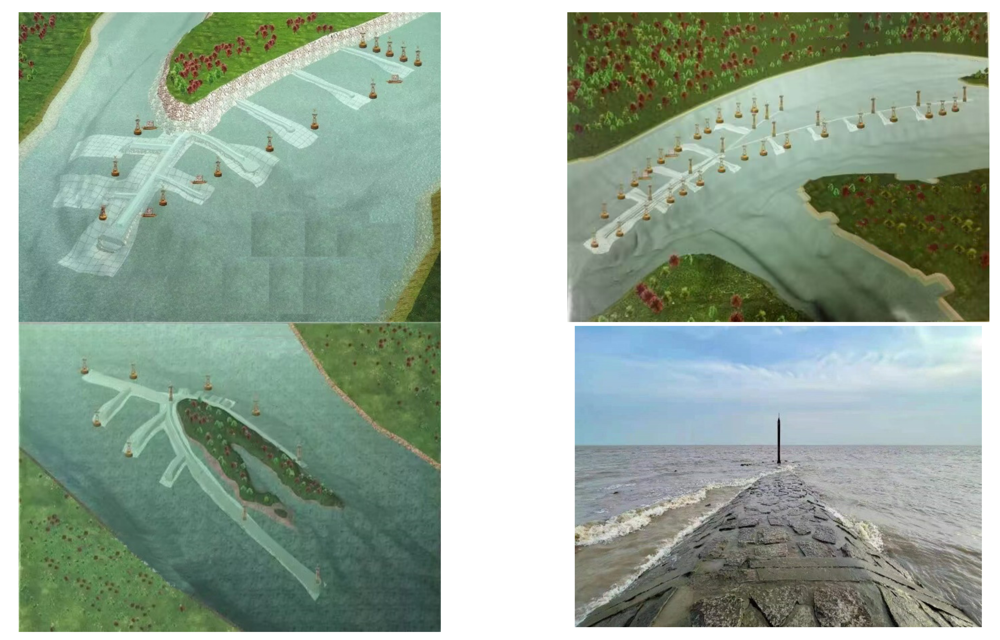
The smooth operation of waterways has promoted the development of a green economy. To continuously improve waterway levels, it is usually necessary to adopt structures such as spur dikes, longitudinal dams and lock dams to renovate obstruction sections [1,2]. As a typical regulating structure of water conservancy and waterway engineering, a spur dike functions to narrow the width of a river, adjusting water flow and protecting shoals; it is widely applied in projects of river shoal protection, waterway regulation and sub-grade protection [3,4]. The dam root of a spur dike is connected to the shoal of a river, its head stretches into the river and its axis is orthogonal or oblique to the direction of water flow. According to the relationship between crest elevation and water level, spur dikes can be classified into submerged and non-submerged spur dike [5]. In the regulation of a 12.5-m-deep channel from Nanjing Xinshengwei Harbor to the upstream mouth of the Yangtze River, regulating structures are located at key positions, in combination with dredging engineering construction. The application of spur dikes can increase the water depth of the main channel to improve navigation conditions or increase sediment transport to reduce the cost of channel dredging. However, after the construction of spur dikes, the original riverbed bundle is narrowed, changing the flow conditions and increasing local head loss [6]. The river section below Nanjing of the Yangtze River is a plain sand-bed river, with bed sand that is fine and easy to loosen, where the maximum velocity of water can exceed 2.5 m/s, and the scour resistance of the river bed is poor; thus, the issue of scour protection near the regulating structures appears especially important for engineering design [7]. To secure the safety and stability of the submerged spur dikes and other regulating structures throughout the construction and operation period, the regulating structures use soft mattresses that are adaptable to river adjustments, such as river bottom protection. Some applications of submerged spur dike in engineering which is located at Yangtze River below Nanjing are shown in Figure 1.
Currently, studies on the hydrodynamic characteristics of the heads of spur dikes and local scour focus on non-submerged spur dikes. Pandey et al. [8] carried out a comprehensive survey based on machine learning. For this purpose, three new machine learning techniques were developed to predict the time variation in scour depth around vertical wall spur dikes in two key areas (front edge and wake) of a cohesive sediment mixture. An experimental study by Nasrollahi et al. [9] found that the maximum scour depth decreased with the increase of the permeability of the groin dam, and these authors also studied the relationship between scour depth and time. Through flume experiments, Jeon et al. [10] studied the three-dimensional flow structure and turbulence flow mechanism around a non-submerged spur dike with a wall attached at a low aspect ratio, and found that the flow mechanisms are related to the horseshoe vortex, shear layer and secondary flow. Zhang et al. [11] established a mathematical 3D model of the local scour of turbulent flow that considered the vertical flow effect to conduct a simulation study on the local scour of non-submerged spur dikes in tidal reaches. Based on flume tests, Zhang et al. [12] investigated the effects of relative roughness and groin profile on the morphological characteristics of a scour hole. The change of resistance caused by hydraulic parameters has an effect on the hydrodynamic force of the river channel and the change of these factors should be taken into account for the scouring and silting of the river bed [13,14]. Zhang et al. [15] numerically simulated the local scour of non-submerged spur dikes with a combination of the 3D Lagrangian-Eulerian method and two-phase flow model. Studies on the local scour of spur dike heads mainly focus on the structure of nearby waterways and contributory factors of the local scour [16,17,18]. Kuhnle et al. [19] used an acoustic Doppler velocity analyzer to measure the three-dimensional flow distribution around a dike with a fixed-bed submerged ladder-type structure. Previous studies [20,21,22,23,24] suggest that the condition of water flow near submerged spur dikes is more intricate than near non-submerged spur dikes. The contributory factors of the depth of local scour of submerged spur dike heads are even more complicated, and research studies have not yet taken the effect of bottom protection into consideration. At present, there are dozens of computational formulas applicable to the depth of local scour from non-submerged spur dike heads, compared to relatively less research on the computational formula for the depth of the local scour of submerged spur dikes [25]. Computational formulas of local scour from spur dikes recommended by existing regulations are applied to non-submerged spur dikes and are not suitable for direct application on submerged spur dikes. Some scholars have studied computational formulas for submerged spur dikes. However, these computational formulas do not take the effect of bottom protection works into consideration [26,27].
Currently, there are more research findings on the local scour of non-submerged spur dikes [28,29], whereas there are almost no research findings on submerged spur dikes with conditions of river bottom protection, as well as in respect of the computational methods of the maximum scouring depth and its distance of submerged spur dikes with the condition of river bottom protection. Generalized simulation in this study was based on the scale of submerged spur dikes as regulating structures in the training of a deep-water channel of the Yangtze River below Nanjing and in the conditions of dynamic sediment, and was properly extended to set up a undistortedly generalized model of the channel. There were 16 groups of scour test data in this study. Through a combination of indoor wide flume normal model tests and field measured data, the scale variation characteristics of the local scour pit of submerged spur dikes were revealed, and a method for calculating the scale of a local scour pit of a submerged spur dike under the condition of bottom protection was put forward.
2. Experimental Methods
Li et al. [30] proposed that the local undistorted model test method can be used to study the local scour of buildings, and the undistorted model test method was used in this study.
2.1. Conditions for Experimental Simulation
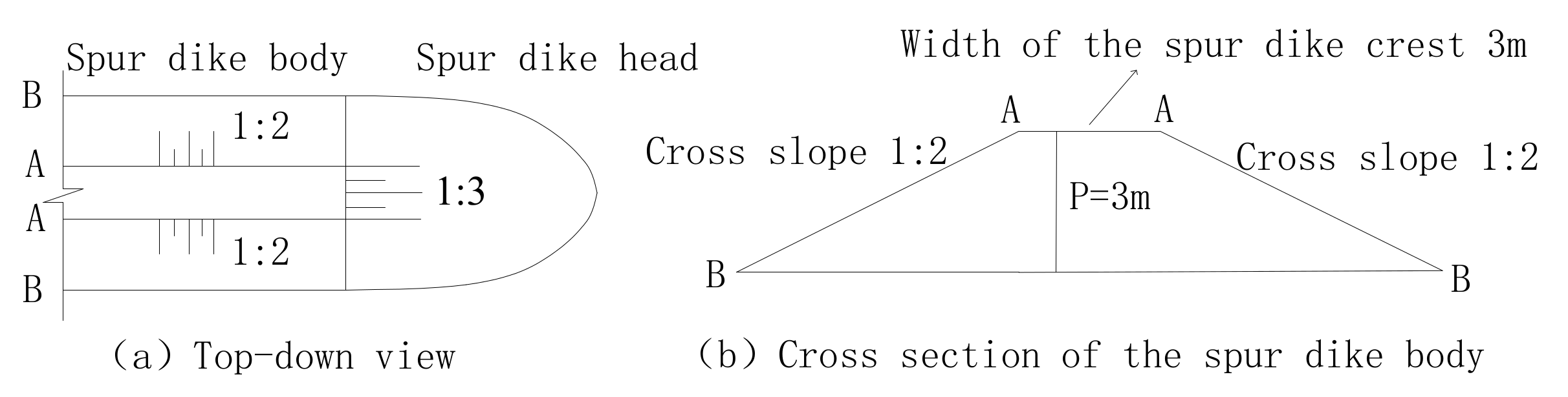
The local undistorted model was used in this experiment, and the water level and discharge of the prototype project were obtained from the measured data. Then, the state of the natural flow was transformed into the flow in the model after further determination of the model scale. Through the verification of the prototype data and data obtained from the model test, the feasibility and accuracy of the test were determined, and the relevant test groups were then repeated several times to obtain the data needed for the test. The flow rate of the flume model test was controlled by a battery Flowmeter to ensure the stability of the outflow, and a tailgate controller was used to ensure the stability of the water level. Based on the scale of engineering works in the deep-water channel of Yangtze River below Nanjing and on its nearby condition of flow and sediment [31], representative conditions for the scale and dynamic sediment of the simulated submerged spur dike structure in the experiment are shown in Figure 2. The width of the dam crest was 3 m, the ratio of the cross slope crosswise to the spur dike body was 1:2; the ratio of the cross slope to the spur dike head was 1:3; the spur dike height was 3 m; and the flow velocity is 1.5 m/s. In the prototype, the ratio of the cross slope to the spur dike head was 1:3 to 1:5; the height of the spur dike was 3 to 9 m; the prototype water was 9 to 15 m deep, with a velocity of 1 to 3 m/s and the median diameter of bed sand was 0.18 mm. By changing these data, the response of the local scour hole depth at the head of the spur dike was analyzed.
2.2. Model Design
The river model should meet the criteria of geometric similarity, motion similarity, and dynamic similarity, which are the conditions that ensure that the results obtained by the experimental model are consistent with the results of the real scenario. Li et al. [30] proposed a relevant formula for the corresponding scale of the river engineering model. The design of the model met the following conditions of similarity:
Similarity of the underwater rest angle of silt: θp = θm,
According to the model site, water supply capacity and other conditions, the range of scales for the model was preliminarily identified. To meet the requirements of similar conditions in model design and convenience to select sand, the geometric scale for the undistorted model was comprehensively analyzed and finally determined as 60. Particles with a median diameter of 0.38 mm was selected as model sand. This satisfied the required similarity of silt incipient motion and underwater rest angle of silt. Each model scale is listed in Table 1.
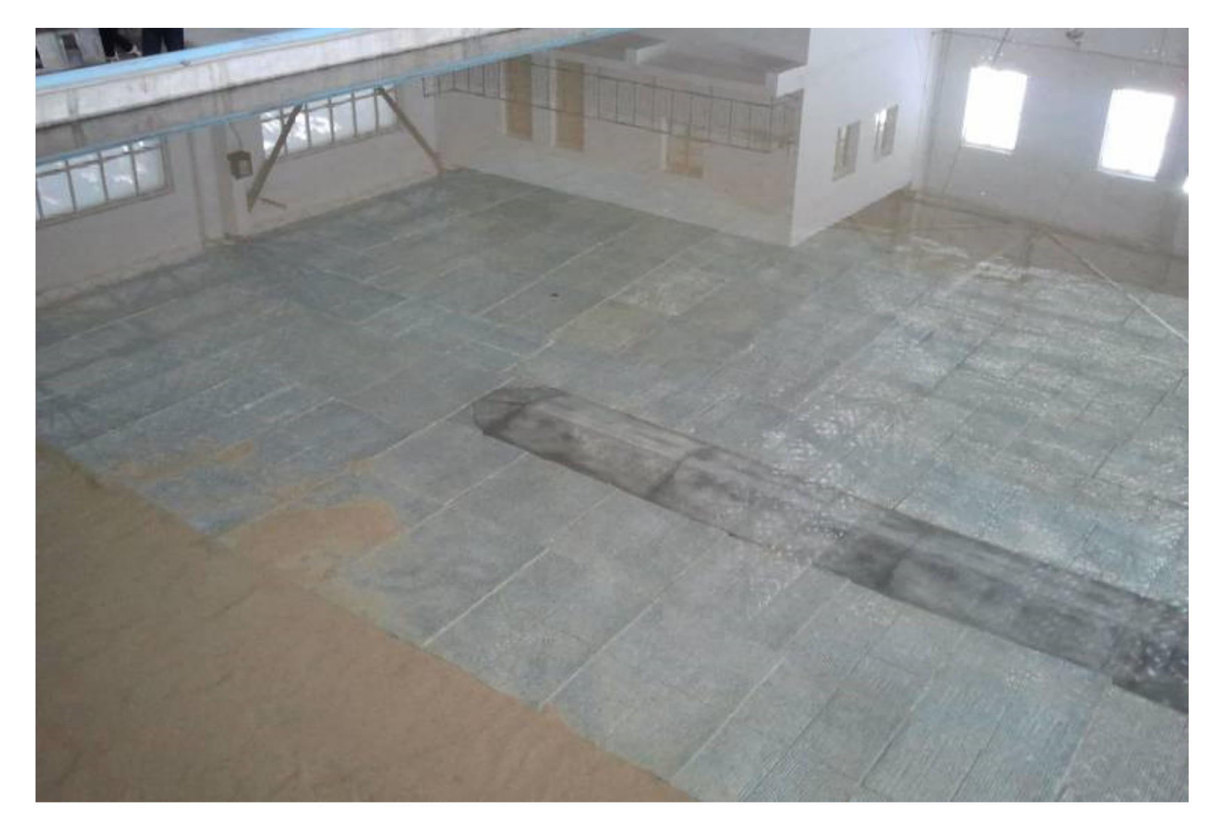
The prototype bottom-protection soft mattress was made from a composite cloth of woven fabric with filaments and non-woven fabric, with its mass per unit area being 500 g/m2 (350 g/m2 of woven fabric + 150 g/m2 of non-woven fabric). Stress carrier on the mattress were concrete blocks with a density of 2400 kg/m3. In the model, the mattress for river bottom protection was simulated by cotton cloth, the concrete blocks were simulated by epoxy resins adhered with a 0.41 g aluminum sheet, and functions of bottom protection structures such as soil protection, adhesion and stability were also simulated. See Figure 3 for a sketch of the model soft mattress.
2.3. Model Setup and Validation
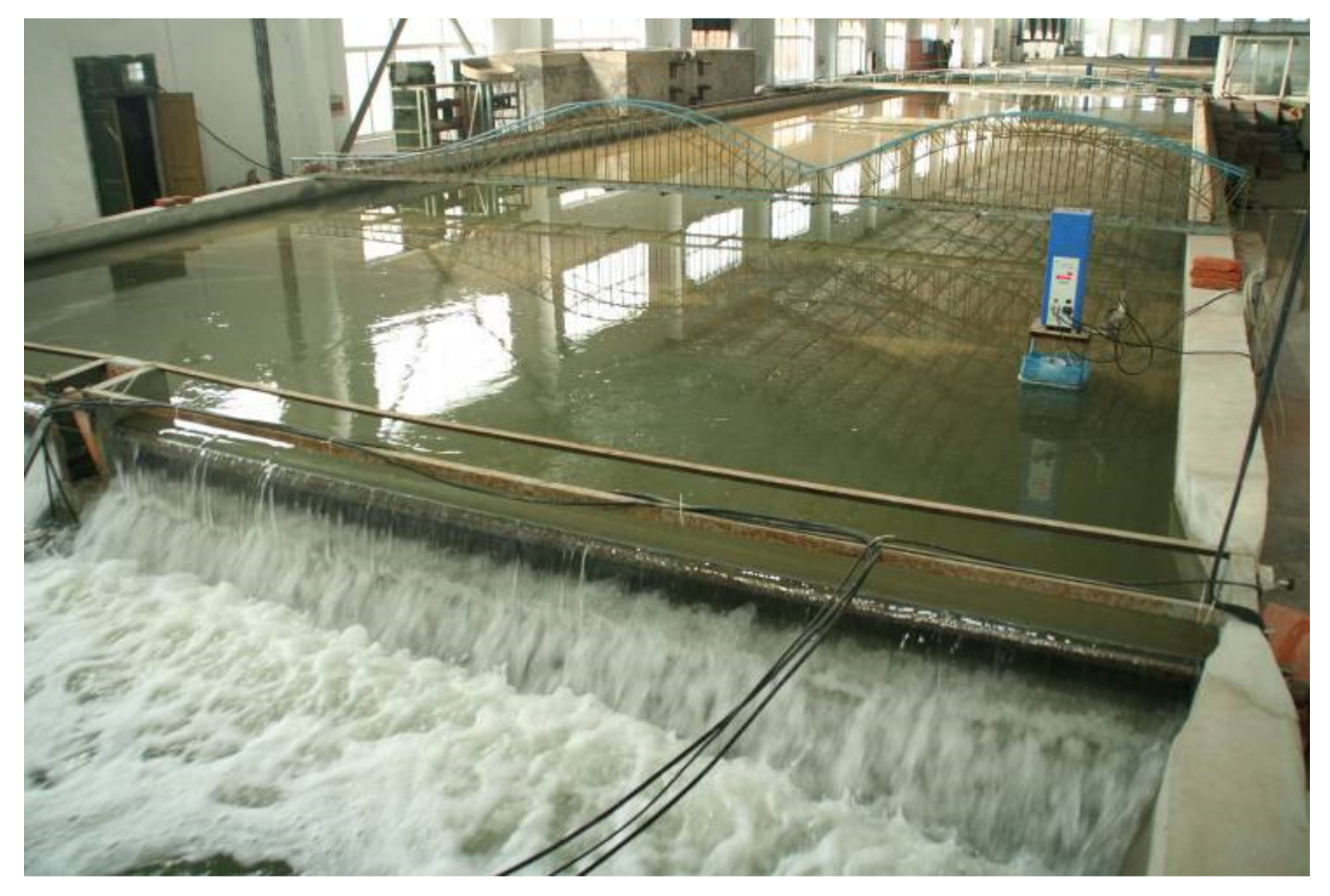
The length of the experimental water channel was about 50 m, and the width was 8 m. The water level of the upstream channel was controlled by its flow, whereas that of the downstream channel was controlled by a stern door as shown in Figure 4. The water level in the model was measured with a raster content gauge, with the accuracy reaching 0.01 mm; the flow velocity was measured with a Nortek current meter with an accuracy of up to 1 mm/s; and the landform was measured with an ultrasonic wave topographic instrument.
Before the experimental study, we took advantage of measured data on the maximum scouring depth of existing submerged spur dikes near the south branch of the Yangtze River to validate the model. The prototype dam was 3.5 m in height, water around the head was 5.8 m deep, velocity of incoming water was approximately 1.7 m/s and actual maximum scouring depth was around 11.7 m, whereas the maximum scouring depth in the model simulation test was about 0.21 m, which translates to a prototype height of about 12.6 m. As a result, the model performed well in the simulation of the local scour near the submerged spur dikes.
2.4. Experimental Tests
The model test of the water channel was to research the rules describing the velocity of incoming water, depth of water, the width of the bottom protection and height of the spur dike corresponding to the local scouring depth and form of submerged spur dikes through a single-factor analysis. As the flow velocity of the stimulated prototype was 1 to 3 m/s, the water was 9 to 15 m deep; the height of the dam was 3 to 9 m, and the width of the bottom protection was 0 to 180 m. When the flow velocity of the simulation model was 0.14 to 0.39 m/s, the water was 0.15 to 0.25 m deep, the height of the dam was 0.05 to 0.15 m, and the width of the bottom protection works was 0 to 3 m. There were 16 experimental groups in total. Several tests were carried out for each test group to determine the corresponding test conditions (See Table 2). These tests focused on the maximum scale of the local scour hole in the state of limit scour equilibrium.
3. Local Scour Features of Submerged Spur Dike
3.1. Relationship between Scale of Local Scour and Relative Height of Dam
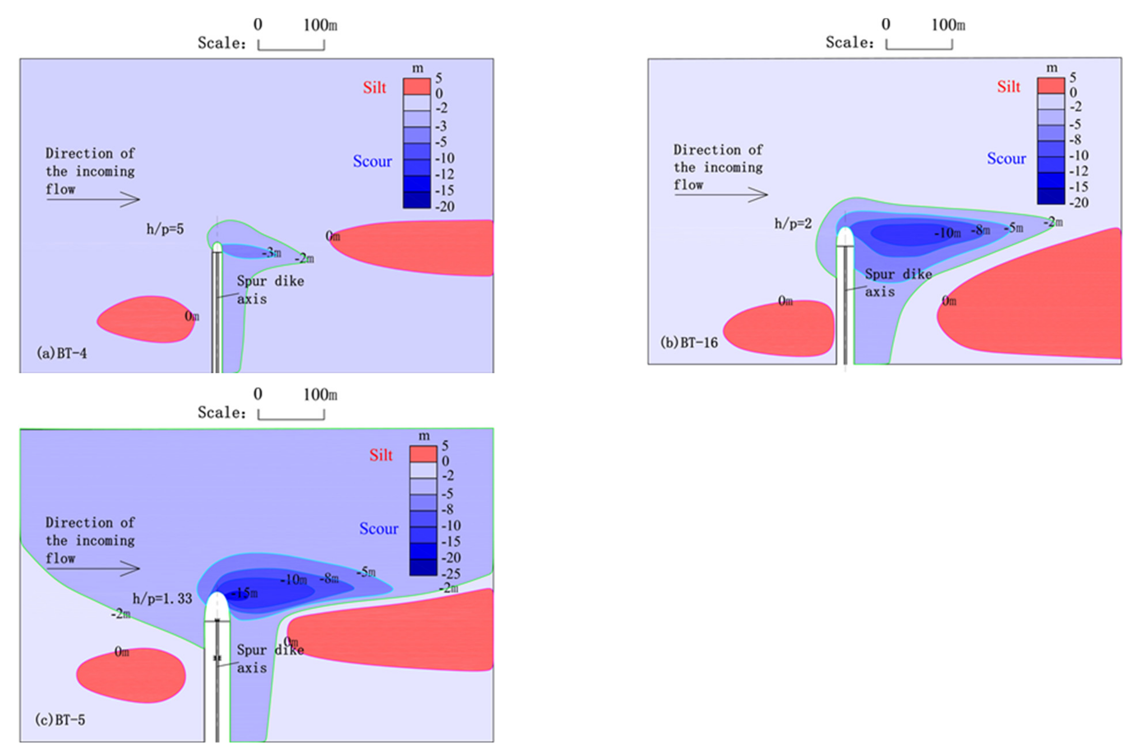
Under the condition of limit scour equilibrium near the dam heads of BT-4, BT-16 and BT-5, the changes in shape of the maximum scale local scour pit are shown in Figure 5. By changing the relative height of the dam, these analyses show that the plane shape of the local scouring pit under the dam is long, and the maximum scouring place is located downstream of the dam head. Through several groups of repeated tests, we concluded that the maximum scour depth near the dam head gradually increases with a decrease in the relative dam height, whereas the maximum scour depth obtained by the model tests in Figure 5a–c were about 3.5, 12.0 and 15.2 m, respectively. In addition, the plane shape of the scour pit gradually moved to the outside of the dam head, and the degree of influence gradually increased. This shows that the relationship between the maximum scale of local scour and relative spur dike height is inversely proportional to a certain range, which is helpful for practical engineering applications.
3.2. Relationship between Scale of Local Scour and Width of Remaining Soft Mattress of Bottom Protection
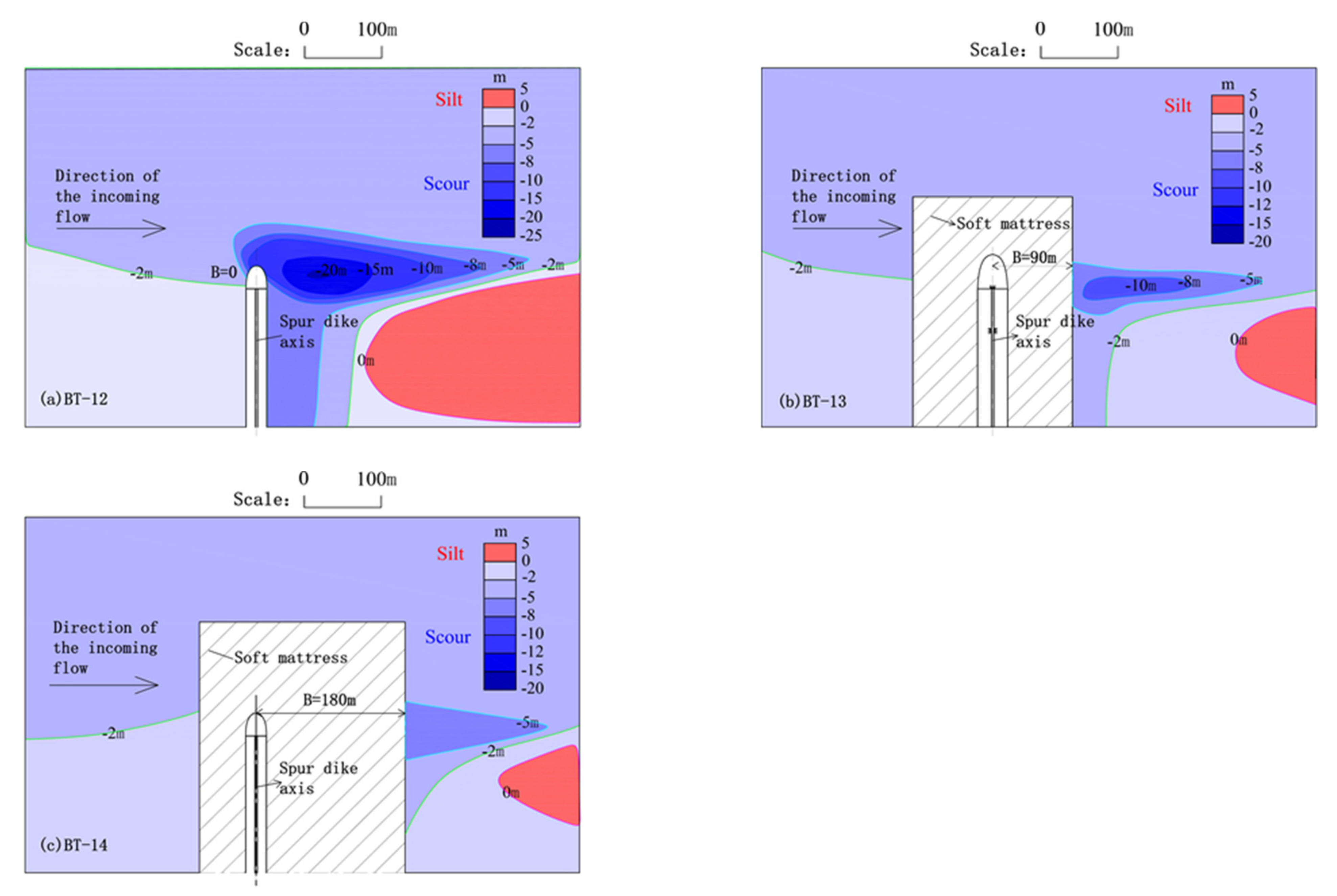
Under the condition of limit scour equilibrium near the dam head of BT-12, BT-13 and BT-14, the shape change of the maximum scale local scour pit is shown in Figure 6. By only changing the width of the remaining row of the bottom, other factors remain the same. The results show that the plane shape of the local scouring pit under the dam is long, and the maximum scouring place is located at the outer edge of the remaining row. Through several groups of repeated tests, we concluded that the maximum scour depth near the dam head gradually decreased with the increase in the protective width of the bottom protection, whereas the maximum scour depths obtained by the model test in Figure 6a–c were about 18.6, 11.2 and 7.6 m, respectively, and the influence of the plane shape of the scour pit was gradually reduced. The distances between the maximum scour pit and axis of the spur dike were about 75, 146 and 210 m, respectively. This showed that the maximum scale of local scour was inversely proportional to the protective width of the residual row of bottom protection in a certain range, which is helpful for further exploring the maximum scale of local scour pit under a state of equilibrium between scour factor and limit scour.
3.3. Relationship between Scale of Local Scour and Flow Force as Well as Longitudinal Slope of the Dam Head
When the velocity of incoming flow was changed, while other factors remained unchanged, the maximum scouring depth near the spur dike head gradually increased with the increasing velocity of the incoming flow, according to the analysis of the scouring form near the dam head of groups BT-6, BT-7, BT-8 and BT-1 (the maximum scouring depth is about 6.7, 8.4, 10.8 and 14.8 m, respectively). The largest scouring pit gradually drew further away from the dam (distances from the maximum scouring depth to the dam axis were about 25, 35, 40 and 55 m, respectively). Groups BT-15, BT-16 and BT-12 also had the same changing characteristics.
When the longitudinal slope of the dam head was changed, while other factors remained, the maximum scouring depth near the dam head gradually decreased, with the gradient of the dam head slackening according to the comparative analysis of the scouring form near the dam head of groups BT-1 and BT-16 (the biggest scouring depth is about 14.8 and 12.0 m, respectively). The largest scouring pit also drew further away from the dam. Groups BT-8 and BT-15 also had the same changing characteristics.
4. Calculating Research on the Scale of Local Scour under the Condition of Bottom Protection
4.1. Dimensional Analysis
According to relevant findings from of the flume experiments, this study explored the computational formula for scouring depth and the distance of the submerged spur dike head under the condition of bottom protection based on principles of dimensional analysis.
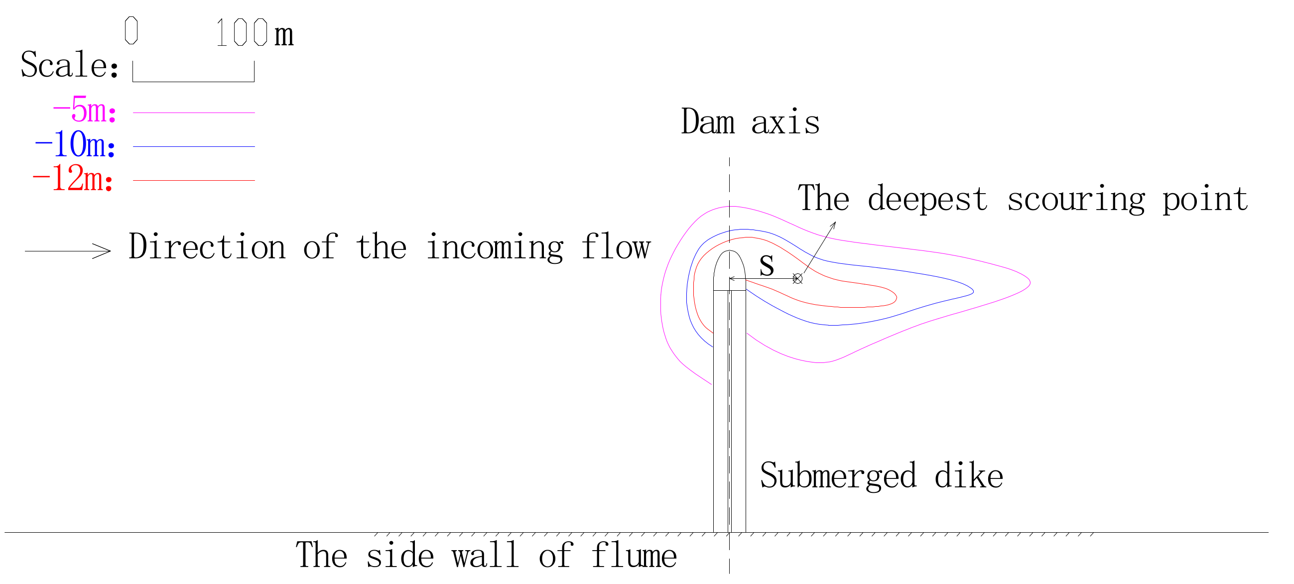
The comprehensive analysis suggested that the largest scouring depth near the dam head D and its distance from the dam axis S (see Figure 7 for depiction of distance S) were connected by the following factors: (a) Velocity of dam-surrounding flow and advancing velocity v of the slope toe of the dam head; (b) water depth h in front of the dam; (c) paving width B of the remaining soft mattress near the dam; (d) dam height P; (e) the grain size d of the bed material; and (f) longitudinal gradient coefficient m of the dam head.
Every relevant factor can be transformed into Equations (7) and (8):
This study focused on a submerged orthogonal spur dike with a 90° jet angle θ. The formula ignores the intersection angle; the influence of the sediment grain size d is reflected by incipient velocity of sediment vc. The volume weight of sediment γs and that of water γ both have constant values that can be ignored. Therefore, Equations (7) and (8) can be simplified as the dimensionless forms in Equations (9) and (10):
We analyzed the relationship between scouring depth and each factor by conducting a single-factor analysis. Therefore, Equations (9) and (10) can be further expanded into Equations (11) and (12):
In these formulas, the functions and mainly reflect the influence of flow dynamic on local scouring depth and distance; functions and mainly reflect the influence of the dam height on local scouring depth and distance; functions and mainly reflect the influence of the width of the remaining soft mattress of bottom protection on local scouring depth and distance; functions and mainly reflect the influence of the longitudinal slope of the dam head on local scouring depth and distance; and k1 and k2 are constant coefficients.
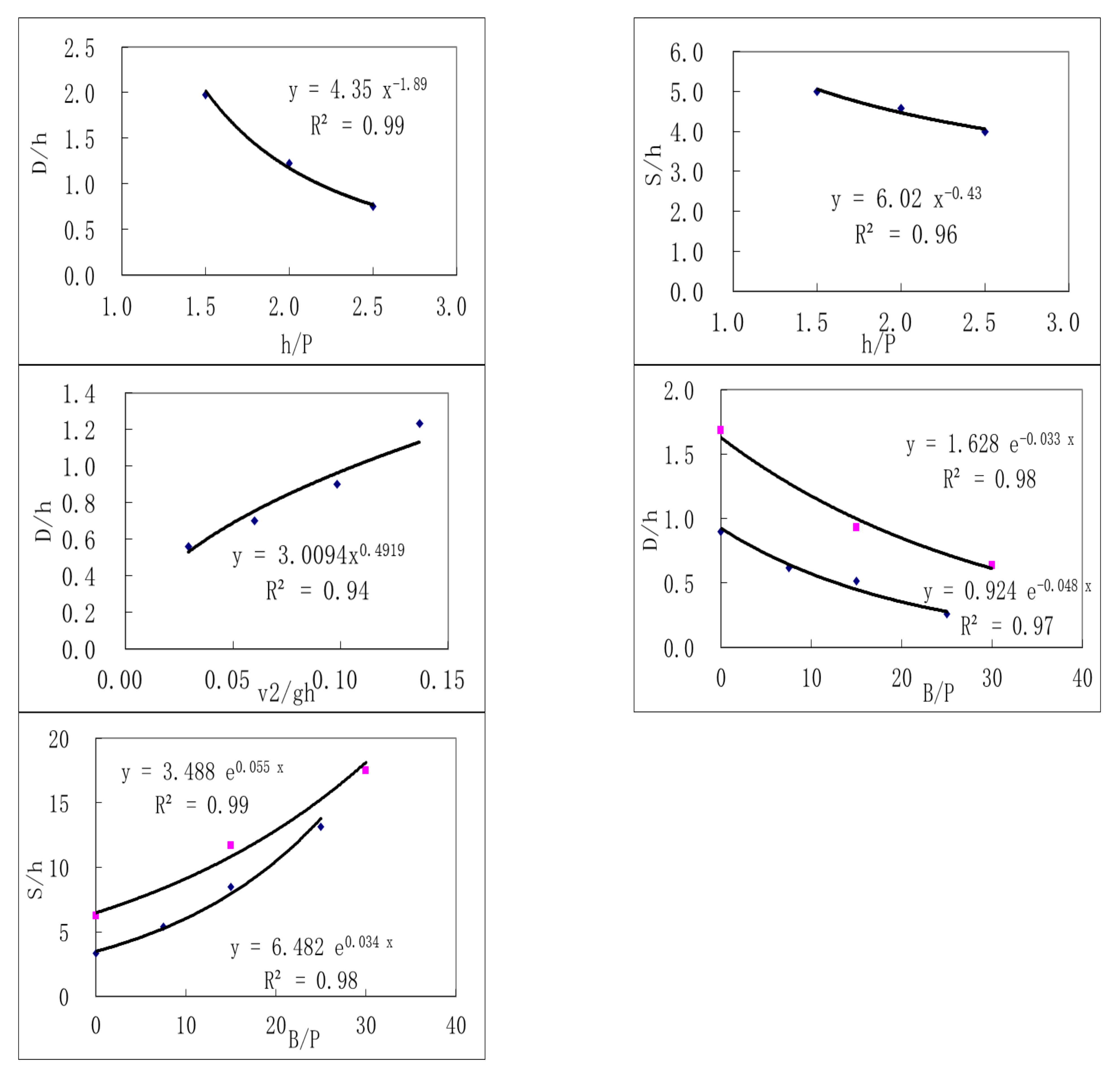
We used the model test data to conduct a single-factor fitting analysis of each function in Equations (11) and (12) to determine the basic dimensional form of each function. As shown in Figure 8, the correlation between relative dam height, incoming flow force, scouring depth, and distance can be expressed by a power relation, with a fitting correlation coefficient of approximately 0.94~0.99. The correlation between the relevant width of bottom protection, longitudinal slope of the dam head, scouring depth, and distance can be expressed by an exponential relation, with a fitting correlation coefficient of approximately 0.96~0.99. The pink point is expressed the relationship which is in remaining soft mattress of bottom protection.
4.2. Calculating Research of the Largest Depth of Local Scour
Based on the results of the single-factor fitting analysis, we used the experiment and the measured data of the relevant construction site downstream of the Yangtze River [32], and we found that the grain size range of the bed material was 0.06~0.20 mm and mainly comprised sand. The ratio between the submerged orthogonal spur dike height and water depth was about 0.25~0.67; the ratio between the width of the bottom protection and dam height was about 0~30; and the velocity range of the incoming flow was 1~3 m/s with the range of the longitudinal slope coefficient of the dam head being 3~5. The single-factor fitting analysis led to the creation of Equation (13), which is suitable for the maximum local scouring depth of the submerged spur dike head on plain sand-bed rivers.
Figure 9 shows the formula calibration results. We found that the fitting effect of the calculated value of the formula and measured values were mostly accurate with a fitting correlation coefficient of approximately 0.85.
4.3. Calculating Research of the Distance from the Deepest Local Scoring Point to the Dam Axis
Using dimensional analysis and fitting correlation, an Equation (14) suitable for calculating the distance from the maximum scouring depth of submerged spur dike head to the axis of the spur dike head in plain sand-bed rivers was established.
Comparisons between the calculated results of Equation (14) and experimentally measured results are shown in Figure 10. The experimentally measured results differ by 20% from the calculated results. We found a good fitting effect between calculated values and measured values, with a fitting correlation of approximately 0.9. In the formula, S is the distance from the maximum scouring depth point near the dam head to the dam axis, m. The meaning of the other symbols are the same as in Equation (13).
4.4. Analysis of Test
Pinter et al. [33] traced and analyzed the water level changes in the Mississippi River and Missouri River during a period of constant discharge. Tian et al. [34] believe that a double bank regulation of spur dikes can improve sediment transport capacity and play a positive role in the scour and deposition of the Yellow River. Cao et al. [35] developed an ecological slope protection structure and analyzed the action mechanism of various structures according to characteristics of hydrology, sediment, riverbed composition and the current ecological environment in the lower reaches of the Yangtze River. This has also been applied to a deep-water channel 12.5 m below Nanjing of the Yangtze River, achieving remarkable economic and ecological benefits, leading to increased popularization and application. In this study, the dimensional analysis method was used to evaluate the maximum depth of the local scour and the distance from the deepest point of local scour to the dam axis. According to previous research on factors affecting the local scour of submerged spur dams, a single-factor analysis method was used to establish an applicable formula for the maximum depth of local scour and the distance from the deepest point of local scour to the axis of the dam in submerged spur dikes in plain fine sand rivers. As shown in Figure 7 and Figure 8, there is a corresponding relationship between experimentally measured data and the data from the model prototype. The difference between the prototype data and the experimental data was small when applying the relevant research formula; therefore, this calculation formula is effective for using in engineering applications. The water depth and velocity in the formula can be obtained through numerical model calculations or a physical model test in the whole river reach. The starting velocity of sediment can be calculated by theoretical formula, and the structural parameters of the dam are obtained from engineering design data. This formula is suitable for plain fine sand rivers, and from a perspective of partial safety, differences in multi-structures of riverbed composition were not taken into account.
5. Conclusions
Submerged spur dikes have been widely used in channel and river regulation in the middle and lower reaches of the Yangtze River. The conclusions of this study are as follows:
- (1)
- Currently, the number of research findings on local scouring characteristics of renovating buildings in submerged spur dikes is relatively low. Effective methods of calculating methods to reach the biggest local scouring depth near the submerged spur dike and distance under conditions of bottom protection have not been established.
- (2)
- This paper adopts the undistorted model experimental research method and studies the corresponding relationships among the maximum depth of local scouring and the form of the submerged spur dike head, relative dam height, width of bottom protection, force condition of the incoming flow and longitudinal slope of the dam head. Our findings suggest that the relationships between relative dam height, the force of the incoming flow and scouring depth and distance can be expressed by a power relation, whereas the relationships between the width of the bottom protection, longitudinal slope of the dam head and scouring depth and distance can be expressed by an exponential relation. The formula for the maximum local scouring depth of the submerged spur dike on the plain sand bed and distance to the dam axis under conditions of bottom protection was established based on the principles of dimensional analysis, which can be used as a reference for protective measures.
- (3)
- The water depth and velocity in the formula can be provided by numerical model calculations or a physical model test of the whole river reach. The starting velocity of sediment can be calculated by theoretical formula, and the structural parameters of the dam can be obtained from engineering design data. This formula can be used as a reference for the application of submerged dams in plain river regulation projects.
Author Contributions
Conceptualization, H.X.; Data curation, H.X. and Y.L.; Funding acquisition, H.X.; Methodology, H.X. and Y.L.; Experiment, H.X., Y.L. and Z.Z.; Resources, H.X. and X.W.; Supervision, X.W. and Z.Z.; Validation, Y.L. and Z.Z.; Visualization, F.Z.; Writing—original draft, H.X. and Y.L.; Writing—review and editing, Y.L. and F.Z. All authors have read and agreed to the published version of the manuscript.
Funding
This research was funded by the National Key R&D Program of China (2022YFC3204504), the Jiangsu Water Conservancy Science and Technology Project (2021004, 2021035), the Follow up Work Item of the Three Gorges Project (126302001000200002), the Innovative Team Project of Nanjing Hydraulic Research Institute (Y220011) and Jiangsu Innovative and Entrepreneurship Talent Program (JSSCBS20211326).
Data Availability Statement
The data presented in this study are available from the responding author upon request.
Acknowledgments
We would like to thank the Construction Headquarters of Deep-water Channel Project of the Yangtze River and Changjinag Waterway Bureau for providing basic data and other technical support.
Conflicts of Interest
The authors declare no conflict of interest.
Nomenclature
| Horizontal scale | v | Velocity of flow (m/s) | |
| Vertical scale | B | Width of bottom-protection soft mattress (m) | |
| Flow velocity scale | vc | Incipient velocity of sediment (m/s) | |
| Scale of silt incipient motion | γs | Volume weight of sediment (N/m3) | |
| Time scale of water flow movement | γ | Volume weight of water (N/m3) | |
| Time scale of riverbed erosion and deposition | θ | Jet angle (rad) | |
| θp | Underwater rest angle of prototype sand | m | Longitudinal grade of the dam head |
| θm | Underwater rest angle of model sand | g | Gravitational acceleration (m/s2) |
| Scale of the dry density of silt | d | Grain size d of the bed material (mm) | |
| αq | Scale of bed material transport rate of unit width | D | Largest scouring depth near the spur dike head (m) |
| P | Height of spur dike (m) | S | Distance from the dam axis near the spur dike head (m) |
| e | Euler number | h | Pre-scouring water depth at the spur dike (m) |
References
- Yang, Y.; Zheng, J.; Zhang, M.; Zhu, L.; Zhu, Y.; Wang, J.; Zhao, W. Sandy riverbed shoal under anthropogenic activities: The sandy reach of the Yangtze River, China. J. Hydrol. 2021, 603, 126861. [Google Scholar] [CrossRef]
- Yang, Y.; Zheng, J.; Zhang, W.; Zhu, Y.; Chai, Y.; Wang, J.; Wen, Y. Quantitative relationship between channels and bars in a tidal reach of the lower Yangtze River: Implications for river management. J. Geogr. Sci. 2021, 31, 1837–1851. [Google Scholar] [CrossRef]
- Przedwojski, B. Bed topography and local scour in rivers with banks protected by groynes. J. Hydraul. Res. 1995, 33, 257–273. [Google Scholar] [CrossRef]
- Abdel-Mawla, S.; Khaled, M. Application of Permeable Groins on Tourist Shore Protection. In Ocean Wave Measurement and Analysis (2001); Amer Society of Civil Engineers: Reston, VA, USA, 2002. [Google Scholar]
- Ying, Q.; Jiao, Z. Hydraulics of Spur Dike; Ocean Press: Beijing, China, 2004. (In Chinese) [Google Scholar]
- Xia, Y.; Cai, Z.; Xu, H. Interaction between new submerged spur dike and water flow in deepwater channel regulation. Port Waterw. Eng. 2018, 10, 137–142. (In Chinese) [Google Scholar]
- Cao, M.; Wang, L.; Shen, X. Analysis on features and difficulties during the construction process of deep water navigation channel project in the Yangtze River below Nanjing. Port Waterw. Eng. 2019, 10, 1–8. (In Chinese) [Google Scholar]
- Pandey, M.; Jamei, M.; Ahmadianfar, I. Assessment of scouring around spur dike in cohesive sediment mixtures: A com-parative study on three rigorous machine learning models. J. Hydrol. 2022, 606, 127330. [Google Scholar] [CrossRef]
- Nasrollahi, A.; Ghodsian, M.; Neyshabour, S.S. Local Scour at Permeable Spur Dikes. J. Appl. Sci. 2008, 8, 3398–3406. [Google Scholar] [CrossRef] [Green Version]
- Jeon, J.; Lee, J.Y.; Kang, S. Experimental Investigation of Three-Dimensional Flow Structure and Turbulent Flow Mechanisms Around a Nonsubmerged Spur Dike with a Low Length-to-Depth Ratio. Water Resour. Res. 2018, 54, 3530–3556. [Google Scholar] [CrossRef]
- Zhang, X.; Dou, X.; Wang, X.; Wang, H.; Zhao, X.; Xu, X. 3-D numerical modeling of local scour processes around spur dikes in tidal rivers. Adv. Water Sci. 2012, 23, 222–228. (In Chinese) [Google Scholar]
- Zhang, L.; Wang, P.; Yang, W.; Zuo, W.; Gu, X.; Yang, X. Geometric Characteristics of Spur Dike Scour under Clear-Water Scour Conditions. Water 2018, 10, 680. [Google Scholar] [CrossRef] [Green Version]
- Pasquino, V.; Gualtieri, P.; Doria, G.P. On Evaluating Flow Resistance of Rigid Vegetation Using Classic Hydraulic Roughness at High Submergence Levels: An Experimental Work. In Hydrodynamic and Mass Transport at Freshwater Aquatic Interfaces; Springer: Cham, Switzerland, 2016; pp. 269–277. [Google Scholar] [CrossRef]
- Aberle, J.; Järvelä, J. Flow resistance of emergent rigid and flexible floodplain vegetation. J. Hydraul. Res. 2013, 51, 33–45. [Google Scholar] [CrossRef]
- Zhang, H.; Mizutani, H.; Nakagawa, H.; Kawaike, K. Euler–Lagrange model for local scour and grain size variation around a spur dyke. Int. J. Multiph. Flow 2015, 68, 59–70. [Google Scholar] [CrossRef]
- Chen, Y.; Lu, Y.; Yang, S.; Mao, J.; Gong, Y.; Muhammad, W.I.; Yin, S. Numerical Investigation of Flow Structure and Turbulence Characteristic around a Spur Dike Using Large-Eddy Simulation. Water 2022, 14, 3158. [Google Scholar] [CrossRef]
- Kang, J.; Yeo, H.; Jung, S. Flow Characteristic Variations on Groyne Types for Aquatic Habitats. Engineering 2012, 4, 809–815. [Google Scholar] [CrossRef] [Green Version]
- Alauddin, M.; Hossain, M.M.; Uddin, M.N.; Haque, M.E. A Review on Hydraulic and Morphological Characteristics in River Channels Due to Spurs. Int. J. Geol. Environ. Eng. 2017, 11, 387–394. [Google Scholar]
- Kuhnle, R.A.; Jia, Y.; Alonso, C.V. Measured and Simulated Flow near a Submerged Spur Dike. J. Hydraul. Eng. 2008, 134, 916–924. [Google Scholar] [CrossRef]
- Kuhnle, R.A.; Alonso, C.V.; Shields, F.D. Local Scour Associated with Angled Spur Dikes. J. Hydraul. Eng. 2002, 128, 1087–1093. [Google Scholar] [CrossRef] [Green Version]
- Wang, J. Study of the unclear water local scour depth of spur dike. J. Hefei Univ. Technol. 2002, 25, 1184–1186. (In Chinese) [Google Scholar]
- Nacy, H. Hydraulic evaluation of emerged and submerged spur-dikes: Temporal bed evolution and equilibrium state characteristics. Alex. Eng. J. 2005, 5, 279–290. [Google Scholar]
- Gu, Z.; Cao, X.; Gu, Q.; Lu, W.-Z. Exploring Proper Spacing Threshold of Non-Submerged Spur Dikes with Ipsilateral Layout. Water 2020, 12, 172. [Google Scholar] [CrossRef] [Green Version]
- Wang, J.; Fan, H.; Zhu, L. Experimental Study on Mechanism and Shape Characteristics of Flexible and Suspended Dam. China Ocean. Eng. 2014, 28, 869–878. [Google Scholar] [CrossRef]
- Hao, S.; Xia, Y.; Xu, H.; Wen, Y. Review of local scour around submerged spur-dike. In Proceedings of the 16th China Ocean (Shore) Engineering Academic Congress; China Ocean Press: Beijing, China, 2013; pp. 1301–1306. (In Chinese). [Google Scholar]
- Fang, D.; Sui, J.; Thring, R. Impacts of dimension and slop of submerged spur dikes on local scour processes—An experimental study. Int. J. Sediment Res. 2006, 2, 89–100. [Google Scholar]
- Lu, J.; Huang, L.; Zhan, Y. Estimation of local scour depth around submerged spur-dike head. In Proceedings of the 4th International Yellow River Forum on Ecological Civilization and River Ethics; Yellow River Conservancy Press: Zhengzhou, China, 2010; pp. 37–61. [Google Scholar]
- Pandey, M.; Lam, W.H.; Cui, Y.; Khan, M.A.; Singh, U.K.; Ahmad, Z. Scour around Spur Dike in Sand–Gravel Mixture Bed. Water 2019, 11, 1417. [Google Scholar] [CrossRef] [Green Version]
- Zhang, H.; Nakagawa, H. Scour around spur dyke: Recent advances and future researches. Disaster Prev. Res. Inst. Ann. 2008, 51, 633–652. [Google Scholar]
- Li, C.; Jin, D. Experimental Model of River Engineering; China Communications Press: Beijing, China, 1981; pp. 104–110. (In Chinese) [Google Scholar]
- Xu, H.; Xia, Y.; She, J. Experimental Study on Local Scour outside Soft Mattress for Bottom Protection in Tidal Reaches; Nanjing Hydraulic Research Institute: Nanjing, China, 2014. (In Chinese) [Google Scholar]
- Ji, Y.; He, G.; Lu, Y. Model selection and verification for a typical spur dike’s scour depth in Yangtze River Estuary. J. Nanjing Hydraul. Res. Inst. 2000, 4, 43–47. (In Chinese) [Google Scholar]
- Pinter, N.; Thomas, R.; Wlosinski, J. Assessing flood hazard on dynamic rivers. Eos Trans. Am. Geophys. Union 2001, 82, 333. [Google Scholar] [CrossRef]
- Tian, S.; Zhang, F.; Liu, X. Impacts of counterpart spur dikes on river channel erosion and deposition in Lower Yellow River. Adv. Sci. Technol. Water Resour. 2017, 37, 9–13. (In Chinese) [Google Scholar]
- Cao, M.; Shen, X.; Ying, H. Study on ecological structures of waterway regulation in the Yangtze River below Nanjing. Port Waterw. Eng. 2018, 1, 1–11. (In Chinese) [Google Scholar]
Figure 1.
Submerged spur dike in the Yangtze River below Nanjing.

Figure 2.
Sketch of submerged spur dike structure: (a) Top-down view of the spur dike; (b) Cross section of the spur dike body.
Figure 2.
Sketch of submerged spur dike structure: (a) Top-down view of the spur dike; (b) Cross section of the spur dike body.

Figure 3.
Sketch of model soft mattress.

Figure 4.
Sketch of experimental water channel.

Figure 5.
Relationship between the form of local scouring hole and height of dam: (a) when the h/p is equal to 5. (b) when the h/p is equal to 2; (c) when the h/p is equal to 1.33.
Figure 5.
Relationship between the form of local scouring hole and height of dam: (a) when the h/p is equal to 5. (b) when the h/p is equal to 2; (c) when the h/p is equal to 1.33.

Figure 6.
Relationship between the form of the local scouring hole and width of the remaining soft mattress of bottom protection: (a) when the B is equal to 0; (b) when the B is equal to 90 m; (c) when the B is equal to 180 m.
Figure 6.
Relationship between the form of the local scouring hole and width of the remaining soft mattress of bottom protection: (a) when the B is equal to 0; (b) when the B is equal to 90 m; (c) when the B is equal to 180 m.

Figure 7.
Picture of distance from the deepest scouring point near the dam head to the dam axis.

Figure 8.
Single-factor fitting relationship.

Figure 9.
Comparison between experimentally measured values and formula-based computed values of local scouring depth of submerged spur dike head.
Figure 9.
Comparison between experimentally measured values and formula-based computed values of local scouring depth of submerged spur dike head.

Figure 10.
Comparison between calculated values and measured values of the maximum scouring depth of submerged spur dike head.
Figure 10.
Comparison between calculated values and measured values of the maximum scouring depth of submerged spur dike head.


Table 1.
Model scale.
| Name | Signal | Numerical Value |
|---|---|---|
| Horizontal scale | 60 | |
| Vertical scale | 60 | |
| Flow velocity scale | 7.7 | |
| Time scale of water flow movement | 7.7 | |
| Time scale of riverbed erosion and deposition | 112 |
Table 2.
Model tests.
| Group No. | Prototype | Model | ||||||
|---|---|---|---|---|---|---|---|---|
| Dimension of Dam Body | Flow Condition | B(m) | Flow Condition | |||||
| P (m) | Cross Slope of Dam Body | Longitudinal Slope of Dam Head | h (m) | v (m/s) | h (m) | v (m/s) | ||
| BT-1 | 6 | 1/2 | 1/3 | 12 | 2.5 | 0 | 0.20 | 0.32 |
| BT-2 | 6 | 9 | 0.15 | |||||
| BT-3 | 6 | 15 | 0.25 | |||||
| BT-4 | 3 | 1/2 | 1/5 | 15 | 0.25 | |||
| BT-5 | 9 | 12 | 0.20 | |||||
| BT-6 | 6 | 1/2 | 1/3 | 12 | 1.1 | 0 | 0.20 | 0.14 |
| BT-7 | 1.5 | 0.19 | ||||||
| BT-8 | 6 | 1/2 | 1/3 | 12 | 2.0 | 0 | 0.20 | 0.26 |
| BT-9 | 45 | |||||||
| BT-10 | 90 | |||||||
| BT-11 | 150 | |||||||
| BT-12 | 6 | 1/2 | 1/5 | 12 | 3.0 | 0 | 0.20 | 0.39 |
| BT-13 | 90 | |||||||
| BT-14 | 180 | |||||||
| BT-15 | 6 | 1/2 | 1/5 | 12 | 2.0 | 0 | 0.20 | 0.26 |
| BT-16 | 1/2 | 1/5 | 12 | 2.5 | 0 | 0.20 | 0.32 | |
Disclaimer/Publisher’s Note: The statements, opinions and data contained in all publications are solely those of the individual author(s) and contributor(s) and not of MDPI and/or the editor(s). MDPI and/or the editor(s) disclaim responsibility for any injury to people or property resulting from any ideas, methods, instructions or products referred to in the content. |
© 2023 by the authors. Licensee MDPI, Basel, Switzerland. This article is an open access article distributed under the terms and conditions of the Creative Commons Attribution (CC BY) license (https://creativecommons.org/licenses/by/4.0/).
Share and Cite
MDPI and ACS Style
Xu, H.; Li, Y.; Zhao, Z.; Wang, X.; Zhang, F. Experimental Study on the Local Scour of Submerged Spur Dike Heads under the Protection of Soft Mattress in Plain Sand-Bed Rivers. Water 2023, 15, 413. https://doi.org/10.3390/w15030413
AMA Style
Xu H, Li Y, Zhao Z, Wang X, Zhang F. Experimental Study on the Local Scour of Submerged Spur Dike Heads under the Protection of Soft Mattress in Plain Sand-Bed Rivers. Water. 2023; 15(3):413. https://doi.org/10.3390/w15030413
Chicago/Turabian StyleXu, Hua, Yangfan Li, Zeya Zhao, Xiaojun Wang, and Fanyi Zhang. 2023. "Experimental Study on the Local Scour of Submerged Spur Dike Heads under the Protection of Soft Mattress in Plain Sand-Bed Rivers" Water 15, no. 3: 413. https://doi.org/10.3390/w15030413
Note that from the first issue of 2016, this journal uses article numbers instead of page numbers. See further details here.