
Desalinating Real Shale Gas Wastewater by Membrane Distillation: Performance and Potentials


Key Laboratory of the Three Gorges Reservoir Region’s Eco-Environment, Ministry of Education, College of Environment and Ecology, Chongqing University, Chongqing 400045, China
*
Author to whom correspondence should be addressed.
Water 2023, 15(3), 439; https://doi.org/10.3390/w15030439
Submission received: 1 January 2023
/
Revised: 17 January 2023
/
Accepted: 18 January 2023
/
Published: 22 January 2023
(This article belongs to the Special Issue Innovative Membrane Processes for Drinking and Wastewater Treatment)
Abstract
:Shale gas wastewater is a hypersaline industrial effluent in demand of efficient treatment or resource recovery. Membrane distillation (MD) is a heat-driven desalination process of high potential to deal with such streams. However, its application is highly limited by the unsatisfactory hydrophobic membranes that involve a trade-off between vapor permeability and fouling/wetting resistance. Our previous studies highlighted the potential role of an intermediate coating layer of a carbon nanotube (CNT) for the superhydrophobic membrane with 1H,1H,2H,2H-perfluorodecyltriethoxysilane (FAS) grafted to address the trade-off issue against synthetic saline oily wastewater. The work herein investigated its application performance in the continuous concentration and water recovery of real shale gas wastewater, with a commercial PVDF membrane as the reference. The modified membrane recycled 48.2% of the total volume as high-quality water and rejected 99% of feed salinity, achieving a superior concentration rate and flux recovery rate compared to PVDF. The value of the COD, total nitrogen, and ammonia nitrogen in the permeate after the modified membrane was less than 50, 20, and 20 mg/L, meeting the local wastewater discharge standard. It was pointed out that the inorganic fouling for the MD membrane was more of a concern in dealing with a real stream, but the modified membrane exhibited excellent fouling resistance. The cost associated with the treatment was estimated at USD 2.2/m3 for a production capacity of 2000 m3/d. The proposed superhydrophobic membrane has proven to be a feasible alternative from both technical and economic standpoints, offering the potential to improve MD effluent water quality and mitigate membrane fouling.
1. Introduction
Shale gas wastewater is a typical hypersaline industrial stream (total dissolved substances (TDS) > 10,000 mg/L [1]) coming from the hydraulic fracturing process, containing a large number of natural or additive organic components, e.g., hydrocarbons, surfactants, scale inhibitors, or other hard-to-degrade contaminants. The escalating volume of such streams accounts for up to 80% of the total water consumed in the entire exploitation process. Considerable attention has been paid to it due to its potential impact on the local environment considering the high emission of complex compositions [2,3,4,5].
Various technologies have been applied to deal with shale gas wastewater separately or in a hybrid mode. Often, conventional biological treatment lacks robustness due to the hindered metabolism of microorganisms by the hypersalinity, and chemical treatment suffers from high chemical dosage and unsatisfactory reaction reactivity. Membrane-based desalination technology that employs a thin film barrier to recover water resources was successfully applied in seawater desalination, where similar high salinity yet less organic substance versus shale gas wastewater was often found [6]. Recently, pressure-driven membranes (e.g., reverse osmosis) were reported to be susceptible to scaling and fouling issues dealing with such a stream, exhibiting a rapid decline in water flux [7]. Membrane distillation (MD) is considered an alternative membrane-based desalination process since it utilizes the temperature difference as the driving force, which not only adapts recyclable energy from solar or waste heat but also shows a less affected vapor flux by the salt content in the feed [8,9,10,11].
Nevertheless, MD faces fouling and wetting problems, especially those caused by low surface tension foulants (surfactants, grease, etc.) [12,13,14,15,16]. To this end, morphological constructions and low-surface-energy material coatings are effective strategies for enhancing the fouling resistance of hydrophobic membranes [17]. Nanomaterials (e.g., nanoparticle silica and nanofiber carbon nanotubes (CNTs)) are usually used for the interfacial modification of membranes [2,18,19,20]. In particular, the trade-off between fouling resistance and permeability for the modified membranes with silica nanoparticles was recently reported [21,22]. CNT-modified membranes offer another option to enhance both the membrane permeability due to its 1D structure and anti-fouling capability due to its better thermal conductivity, electrical conductivity, and specific surface area [20,23,24,25]. Our previous studies have pointed out that the CNT intermediate layer contributed to ideal permeability and excellent fouling/wetting resistance thanks to the superhydrophobicity and induced slippery interfaces [20]. However, reports on the practical applications of CNT-modified membranes for actual shale gas wastewater are rarely found. Whether the desired performance of enhanced fouling/wetting resistance and mitigated flux decline could be achieved in a real stream of complex organic and inorganic compositions remains unknown.
Hence, in this study, CNT-modified superhydrophobic MD membranes were applied to desalinate real shale gas wastewater. A multiple-cycle test was conducted with the neat commercial PVDF membrane as the control. The permeability performance and fouling behavior of the superhydrophobic membrane were investigated, as well as the water quality with reference to the local standard for water discharge. The capital expenditure and operational costs were also determined. This work intends to provide a theoretical basis and the foundation for the future promotion and application of CNT-modified superhydrophobic membranes.
2. Materials and Methods
2.1. Materials and Chemicals
Commercial polyvinylidene fluoride (PVDF) membranes (Millipore Sigma, Burlington, MA, USA) with a pore size of 0.22 µm and thickness of 125 µm were used as the control. Carbon nanotubes (CNTs) of carboxy-functionalized (XFNANO Co., Ltd., Nanjing, China) with a length of 0.5−2 μm and a purity >95% were used for the membrane surface modification. 1H,1H,2H,2H-Perfluorodecyltriethoxysilane (FAS, C16F17H19O3Si), polyvinyl alcohol (PVA), glutaraldehyde (GA), mineral oil, and other chemicals were purchased from Aladdin Co., Ltd., Shanghai, China. All reagents used in this study were analytical grade and used as received. The real shale gas wastewater was obtained from the Yongye 5-1HF well in the “Rongchang-Yongchuan” block, Baofeng Town, Yongchuan District, Chongqing, China.
2.2. Superhydrophobic Membranes Based on Surface Modification
This superhydrophobic membrane (hereinafter abbreviated as PVDF-CNT-FAS) was fabricated by introducing a CNT layer with a hydroxyl-rich surface on a commercial PVDF substance membrane, followed by FAS grafting. In order to better disperse the carboxy-functionalized CNT (a COOH content of approximatelt 2 wt%), 0.4 g of carboxy-functionalized CNT was placed in 500 mL of a 10 M NaOH aqueous solution and stirred at 90 °C for 5 h. After cooling, the CNT was washed with DI water until it had a neutral pH, and the CNT was filtered and dried to obtain the CNT (CNT-COONa) which facilitated dispersion. Subsequently, the CNT was dissolved in an ethanol solution at a ratio of 0.2 wt% and sonicated for 120 min to disperse the solution uniformly. The obtained CNT suspensions were sprayed onto commercial PVDF membranes (7.5 × 14 cm2) with a surface loading density of 0.42 mg/cm2. To prevent the CNT from peeling off the membrane surface and to enrich the hydroxyl groups on the membrane surface, a 0.1 wt% aqueous PVA solution was then sprayed onto the membrane surface. These CNT-coated membranes were immersed in a mixture of 11.3 g/L of GA cross-linker and 4.4 g/L of HCl catalyst at a temperature of 70 °C for 1 h. The membranes were subjected to a FAS grafting fluorination reaction by immersing the membranes in an ethanolic solution of FAS at a concentration of 4 wt% for 24 h, followed by a thorough rinse with DI water. Finally, the prepared PVDF-CNT-FAS membranes were dried at 105 °C for 6 h and stored in ambient conditions before use.
2.3. Characterization of the Membrane
The morphology of the surface and cross-section of the membrane were investigated via a scanning electron microscope (SEM, SU8010, Hitachi, Tokyo, Japan). A contact angle instrument (SDC-100, Shengding, Kunshan, China) was used to define the hydrophobicity of the membrane. The membrane pore size distribution was determined with a capillary flow porometer (Porolux 1000, IB-FT GmbH, Berlin, Germany). The fouled membrane was characterized using electrochemical impedance spectroscopy (EIS, Admira, Squidstat plus, Phoenix, AZ, USA) to elucidate the fouling/wetting degree.
2.4. Water Quality Monitoring
The mineral element of the shale gas wastewater was analyzed with an inductively coupled plasma series mass spectrometer (ICP-MS, NexION 5000, Perkinelmer, Waltham, MA, USA). The zeta potentials were tested with an electrokinetic analyzer (SurPASS, Anton Paar, Graz, Austria). The organic matter was tested with a steady-state, transient fluorescence spectrometer (EEM, FLS1000. Edinburgh instruments, Edinburgh, UK) and a total organic carbon analyzer (TOC, Shimadzu, Kyoto, Japan).
2.5. MD Experiment
The DCMD device used an acrylic plate with an effective membrane area of 38.2 cm2 and a flow channel size of 106 cm × 36 cm × 1 cm in length, width, and thickness for both the feed and permeation designs. The temperature of the feed and condensation side were set at 70 and 15 °C, respectively, maintained with a temperature circulator. The DCMD unit operated in staggered flow, and the flow rates were adjusted with peristaltic pumps at 500 mL/min on the feed side and 200 mL/min on the permeate side.
The concentration factor (CF) was calculated using the equation of , where and were the volume of the feed and the water recovery in the permeate. The salt rejection rate () was calculated using the equation of , where and were the conductivities of the permeate and feed.
2.6. Characterization of Shale Gas Wastewater
The real shale gas wastewater was taken from a storage tank of the gas gathering station in local Chongqing, China. The wastewater was turbid with a slightly irritating odor, and the supernatant was light yellow after standing with a precipitate at the bottom. The wastewater was shaken well and used for water quality characterization as the raw wastewater, and the measurement results are listed in Table 1.
The water quality characteristics of shale gas wastewater are summarized as follows. (1) Hypersaline. The conductivity of the shale gas wastewater was maintained at 41.4 mS/cm, slightly higher than that of seawater, and the TDS was 21.5 g/L. (2) High-concentration organic contaminants. The pH of this wastewater was neutral at 7.2, and the COD was 1.9 × 10³ mg/L, approximately 18 times the pollutant discharge index of the wastewater plant, in which the total organic carbon content was also high. (3) High mineral content. The original content of calcium, magnesium, barium, iron, and manganese was very high, indicating that the shale gas wastewater may induce severe inorganic scaling. (4) High ammoniacal nitrogen content. The total nitrogen in this wastewater was 153 mg/L, of which 85.6% belonged to ammonium, which may damage the water quality of the permeate side for the MD process due to the potential selective permeate.
3. Results and Discussion
3.1. The Characteristics of the Membrane
Table 2 compares the essential characteristics of the commercial PVDF membrane and the modified superhydrophobic PVDF-CNT-FAS membrane. The virgin membrane exhibits a micro-porous structure in the top view (reported as an average membrane pore size of 0.22 μm [2,20]) and a single homogeneous layer in the cross-section view (a thickness of 125 μm). The modified membrane was loaded with a dense CNT layer, which shows a network fiber structure with a thickness of ca.15 μm [20,24,25]. Accordingly, a denser pore size (approximately 0.18 μm) was found. Another change lies in the surface hydrophilicity, where the virgin membrane has water and oil contact angles of 124 ± 3° and (42 ± 6°), respectively [26]. In contrast, the PVDF-CNT-FAS membrane possesses a superhydrophobic (180°), oleophobic (103°), and slippery (lower than 5°) interface [20,27], indicating the potential anti-fouling and wetting resistance properties due to the metastable Cassie-Baxter state created by the network fiber structure of the CNT layer [20,28,29].
3.2. Performance with Simulated Saline Oily Wastewater
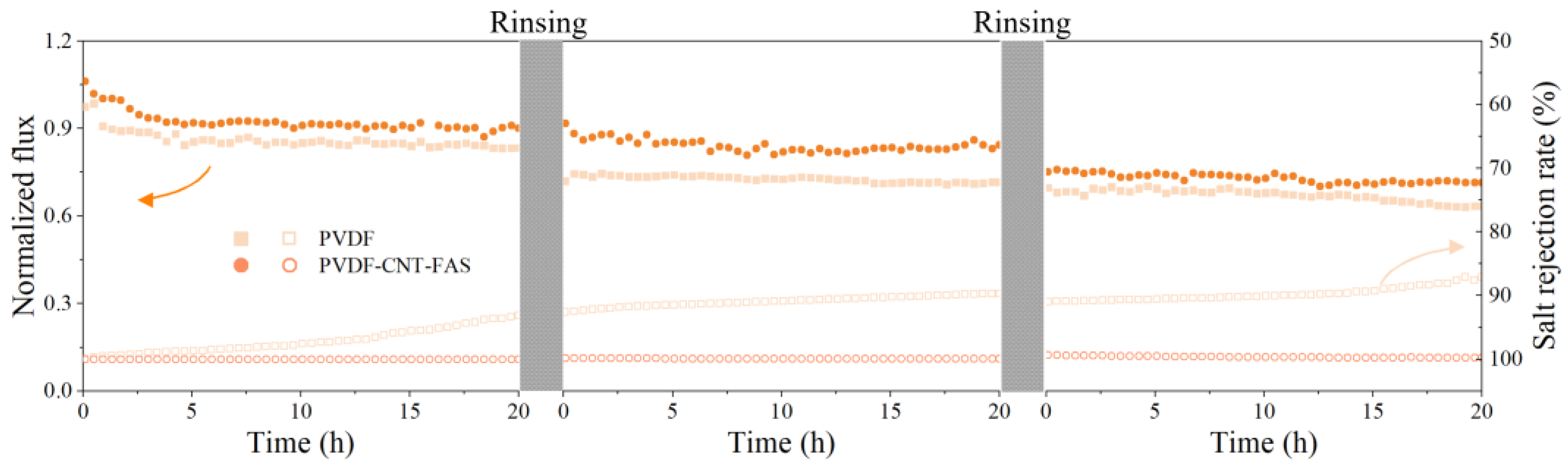
The result of the salt rejection rate is confusing for the indication of the membrane wetting phenomenon under the challenge of real shale gas wastewater [30]. In order to detect the anti-fouling/wetting performance of the PVDF-CNT-FAS and PVDF membranes, the synthetic saline oily wastewater containing sodium dodecyl sulfate (SDS) was used to promote membrane wetting. Figure 1 compares the performance of two membranes, concentrating on the simulated saline oily wastewater. Initially, similar fluxes of 23.8 and 23.2 kg/(m2∙h) were found for the virgin and modified membranes, respectively. Then, both membranes exhibited a gradually declined flux, which was clearer for the commercial one, producing final data of 90%, 80%, and 60% of the initial flux at the end of each cycle, respectively. In addition, the salt rejection of the PVDF membrane was systematically lower than the PVDF-CNT-FAS membrane in each cycle, indicating an occurrence of membrane wetting. Such a finding was consistent with the behavior of the MD membrane dealing with simulated shale gas wastewater, which was ascribed to the pore wetting caused by the continuous addition of surfactants [30]. As shown in Figure 1, the membrane flux did not recover after rinsing for both the PVDF-CNT-FAS and PVDF membranes. Here, the decrease in flux was speculated to be a membrane pore blockage caused by the accumulation of emulsified oil droplets, which was difficult to remove by hydraulic cleaning because of the hydrophobic interaction between the membrane surface and the foulants. Considering the current objective lies just in checking the membrane’s robustness, we did not perform a cleaning analysis in detail in terms of chemical cleaning. In contrast, the overall flux drop was limited (<20%), and the salt rejection was maintained well (>99%) for the PVDF-CNT-FAS membrane. Our results indicated that the CNT network successfully served as a barrier such that the prepared membrane was prevented from severe membrane fouling/wetting.
3.3. Flux and Concentration Factor with Real Shale Gas Wastewater
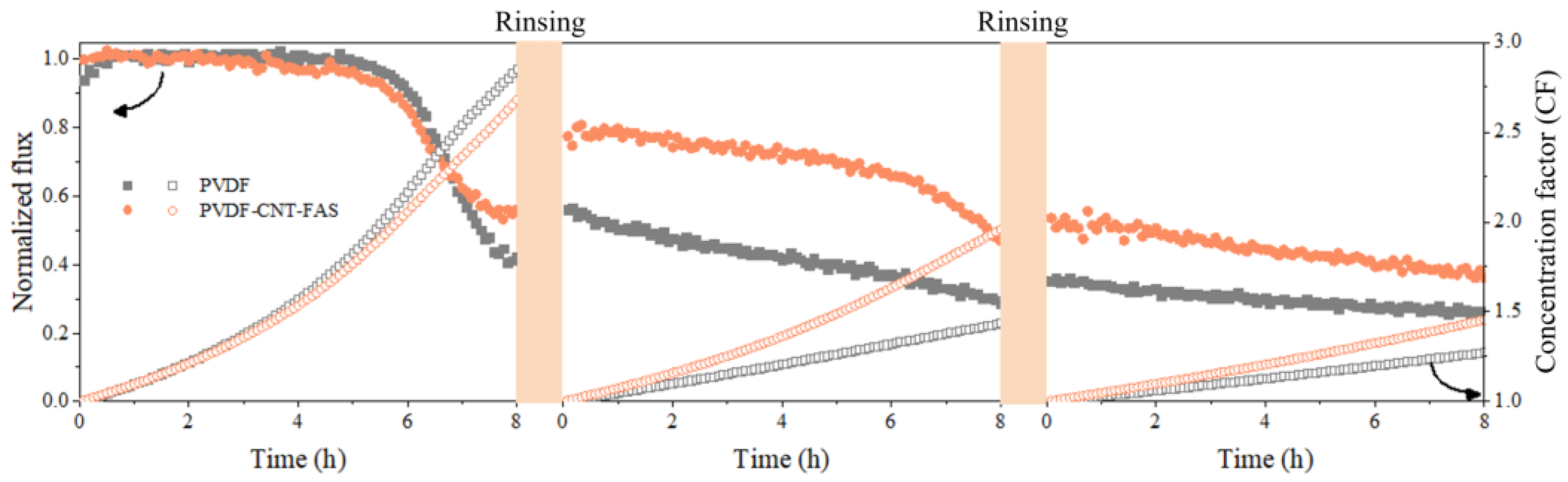
The variation of the normalized flux and concentration factor over time for the PVDF and PVDF-CNT-FAS membranes are illustrated in Figure 2 with continuous concentrations of real shale gas wastewater. In the first cycle, the flux of both membranes started to decrease quickly after 6 h, and the final variation was 60% and 40% for the virgin and modified membranes, respectively. Meanwhile, a slightly higher concentration factor for the PVDF membrane compared to the PVDF-CNT-FAS membrane may be related to the relatively higher initial flux (i.e., 23.6 kg/(m2∙h) for the former and 22.92 kg/(m2∙h) for the latter, respectively. After the first rinsing, the fluxes for the PVDF-CNT-FAS and PVDF membranes were restored to 80% and 60% of the initial values, respectively. The better flux recovery for the modified membrane was probably due to a smooth superhydrophobic interface, agreeing with its contact angle result. In such a case, the foulants would have less time and area to adhere to the membrane interface and thus are more likely to induce reversible fouling, which was washable via physical rinsing [20,21,22,31]. Nevertheless, during the following two-cycle experiments, the flux did not completely recover after physical rinsing, which could be attributed to the adhesion and accumulation of complex foulants on the membrane surface. It was reported that the coupling of the membrane electrochemical reactor and alkaline solution cleaning led to the almost complete removal of severe irreversible fouling [32]. The CNT-coated membrane developed in this study exhibited potential as a membrane electrode, and further study on chemical cleaning could be worthwhile. Furthermore, the flux and concentration factor of the modified membrane were both higher than the control, despite the gradual flux decrease. Figure S1 further compares the volume of desalinated water and the salt rejection data for the two membranes after each cycle. An acceptable salt retention ratio (>99%) found at the end of each cycle suggested a low wetting occurrence for both membranes.
Obviously, vapor permeability loss increased when the real stream was treated, whereas the salt rejection loss was negligible for both membranes, according to the data in Figure 1 and Figure 2. The more complex compositions in the real stream (higher organic substances and more types of ionic species) likely resulted in the server flux’s decline. In line with reports dealing with real shale gas wastewater, the accumulation of inorganic or organic foulants on the membrane surface was responsible for the flux decline described herein [21,22]. The fouling deposit may further prevent salt permeation and increase the mass transfer resistance in such a concentration-dependent manner [22]. The recovered water volume by the modified membrane was gradually higher than the control. Overall, the PVDF-CNT-FAS and PVDF membranes demonstrated 48.2% and 20.5% concentrations for the total volume of the real stream. Such a superior performance for the CNT-modified membrane highlighted its potential in achieving the minimization of shale gas wastewater.
To sum up, the flux and salt retention rate as well as the concentration factor or volume of recovered water for the PVDF-CNT-FAS membrane were all better than the control during the multiple-cycle experiments. The superior flux recovery with a water rinse for the PVDF-CNT-FAS membrane highlighted the importance of the engineered superhydrophobic interface for fouling/wetting resistance.
3.4. Permeate Quality with Real Shale Gas Wastewater
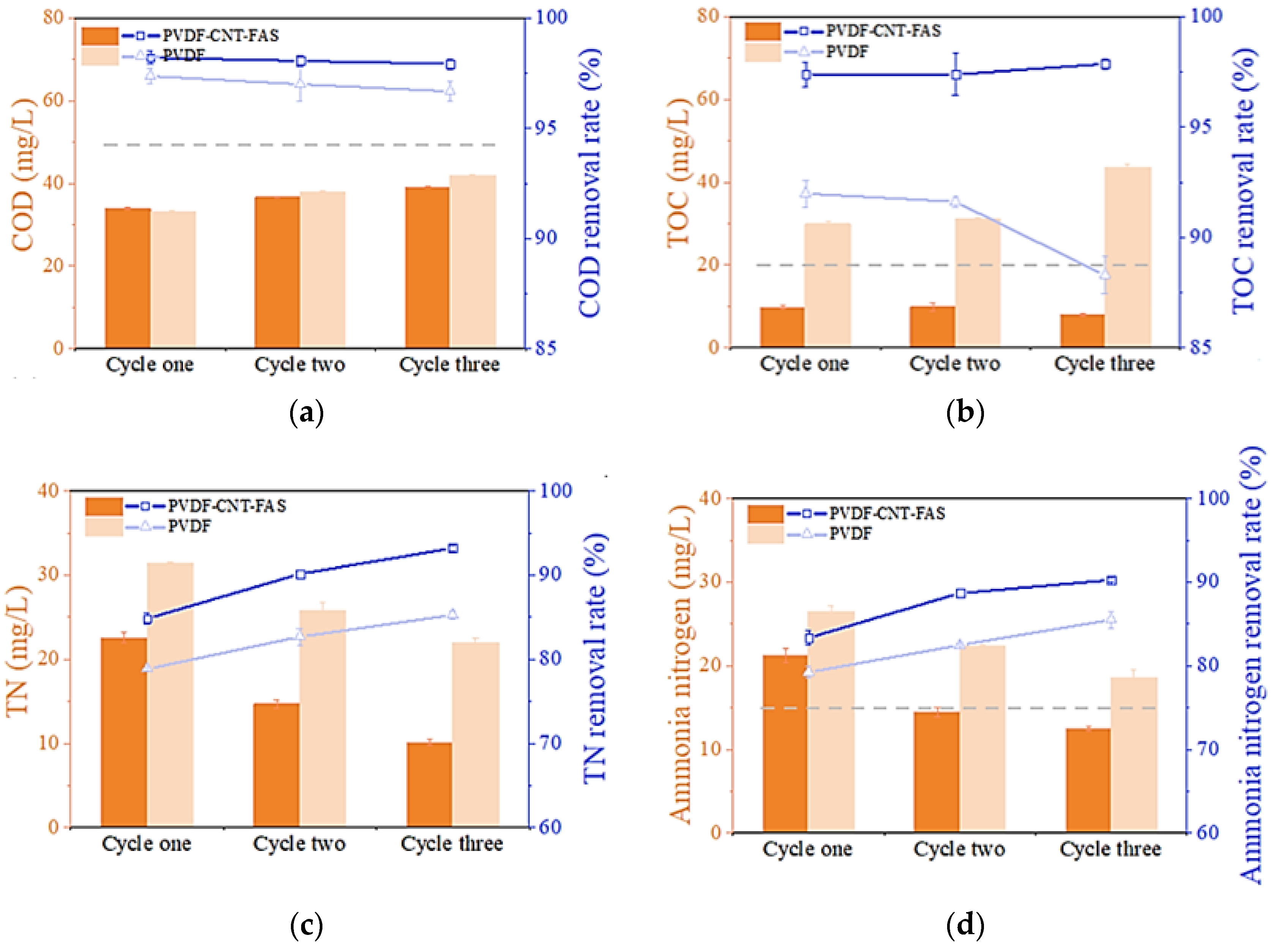
Figure 3 analyzes the quality of the permeate water collected at the end of each cycle in MD. Figure 3a shows that the COD value gradually increased with the cycle number of the experiment for both membranes, and their retention rates were above 95%. The final highest value was found to be less than 50 mg/L, which meets the local standard for wastewater discharge of GB8978-2006. The performance of the two membranes in terms of COD retention was not distinct. Then, as shown in Figure 3b, the TOC content in the permeate (ca. 35 mg/L) was found to exceed the standard value (20 mg/L), and the final removal rate was decreased to less than 90% for the PVDF membrane, which was clearly inferior to the performance of the PVDF-CNT-FAS membrane (the TOC content was ca. 10 mg/L and the removal rate was over 97%). The TOC is considered a more straightforward representation of the organic matter than the COD in water monitoring because several reductive substances, whether organic or inorganic, could induce high COD values [3,33]. Thus, the TOC data in Figure 3b, regarded as a better indicator in this work, suggested that modified membranes could retain the mass transfer of organic substances well since the salt rejection rates of both membranes were nearly satisfactory. Indeed, previous reports have shown that small amounts of benzene, PAHs, and humic organic matter were found in shale gas wastewater, which could result in membrane wetting and fouling [3,5,34]. Considering only a slight leakage of organic compounds (rejection > 90%), we assumed that only some volatile organic compounds were probably transported across these hydrophobic membranes.
Figure 3c,d demonstrates a decreasing concentration of the total nitrogen and ammonia after each cycle of the experiment, respectively. Meanwhile, both membranes exhibited similar concentration levels with retention rates higher than 80%. Table 1 shows that ca. 85.2% of the nitrogen compounds in the real shale gas wastewater were mainly in the form of ammonia nitrogen, which is highly volatile and could easily reach the permeate side of the MD system [35]. As the MD concentration experiment progressed, the concentration of ammonia in the permeate decreased in each case, suggesting more water vapor transfer than ammonia during this experiment. We further speculated that fouling layer formation on the membrane surface possibly hindered the ammonia transfer process and caused a decrease in ammonia flux [35]. The retention rate of ammonia and the total nitrogen with the PVDF-CNT-FAS membrane (80–90%) were better than the PVDF membrane at any concentration level. This suggested that the dense CNT layer facilitated the interception of various pollutants in the wastewater. Nevertheless, ammonia, as a potentially valuable resource, possibly became more volatile under proper conditions (e.g., pH) and had more chance to permeate across the MD membrane. The potential low-impact valorization processes could be considered for its removal or recovery [36,37].
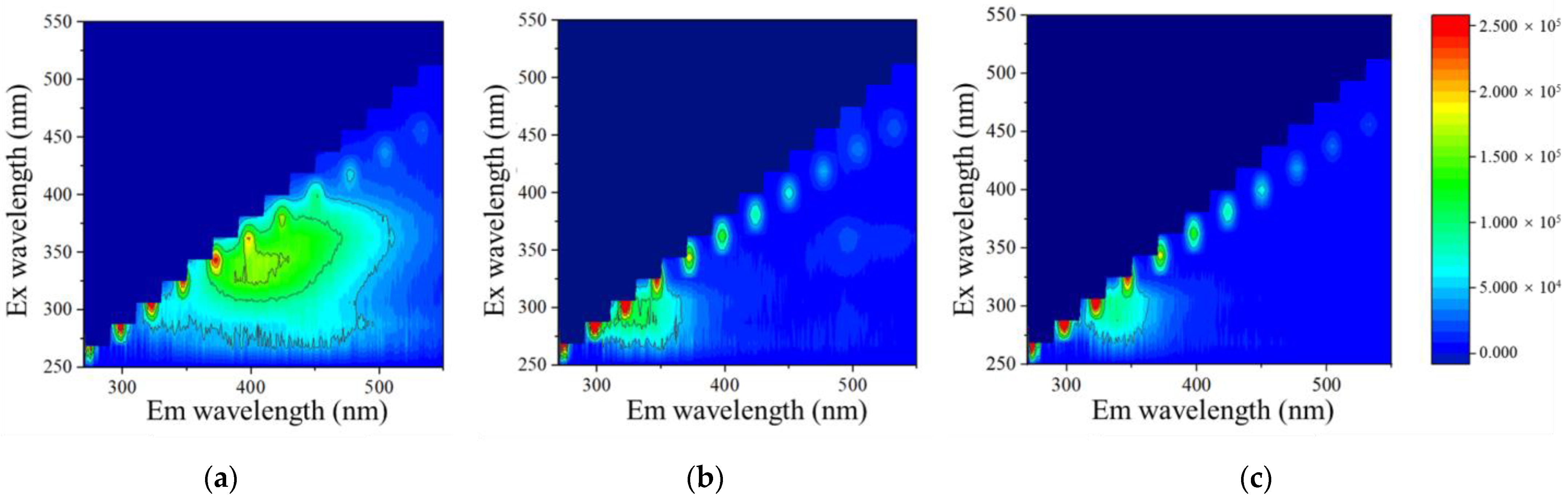
Furthermore, the three-dimensional fluorescence spectroscopy analysis for the feed and permeate was performed, and this data is shown in Figure 4a–c. As shown in Figure 4a, the characteristic fluorescence peak at Ex 325/Em 400 nm indicates that the hydrochloric acid humates were the dominant organic matter in the real stream [4]. Then, in the permeate after three cycles of MD experiments (Figure 4b,c), the fluorescence peak of tryptophan at Ex 325/Em 275 nm was found, likely as a product of the microbial metabolism process [4]. We assumed that this finding (that the peak of tryptophan was visible not in the feed water but in the permeate) was probably due to a masking effect from the stronger fluorescence of humic acids [38]. It was also expected that the humic substances had less mobility toward the hydrophobic membrane, possibly owing to a lowered wetting potential or larger size such that they were easily intercepted, whereas only a small permeance of a protein-like substance (tryptophan) was present after the membrane barrier [39]. Then, the higher fluorescence intensity of tryptophan in the permeate with the control membrane compared to the modified one indicated an increased transfer of organic matter or, in other words, a severer wetting issue for the PVDF membrane. This result was consistent with the higher TOC content for the same membrane type (Figure 3b). In summary, better permeate water quality was achieved with the PVDF-CNT-FAS membrane dealing with shale gas wastewater.
3.5. Membrane Fouling with Real Shale Gas Wastewater
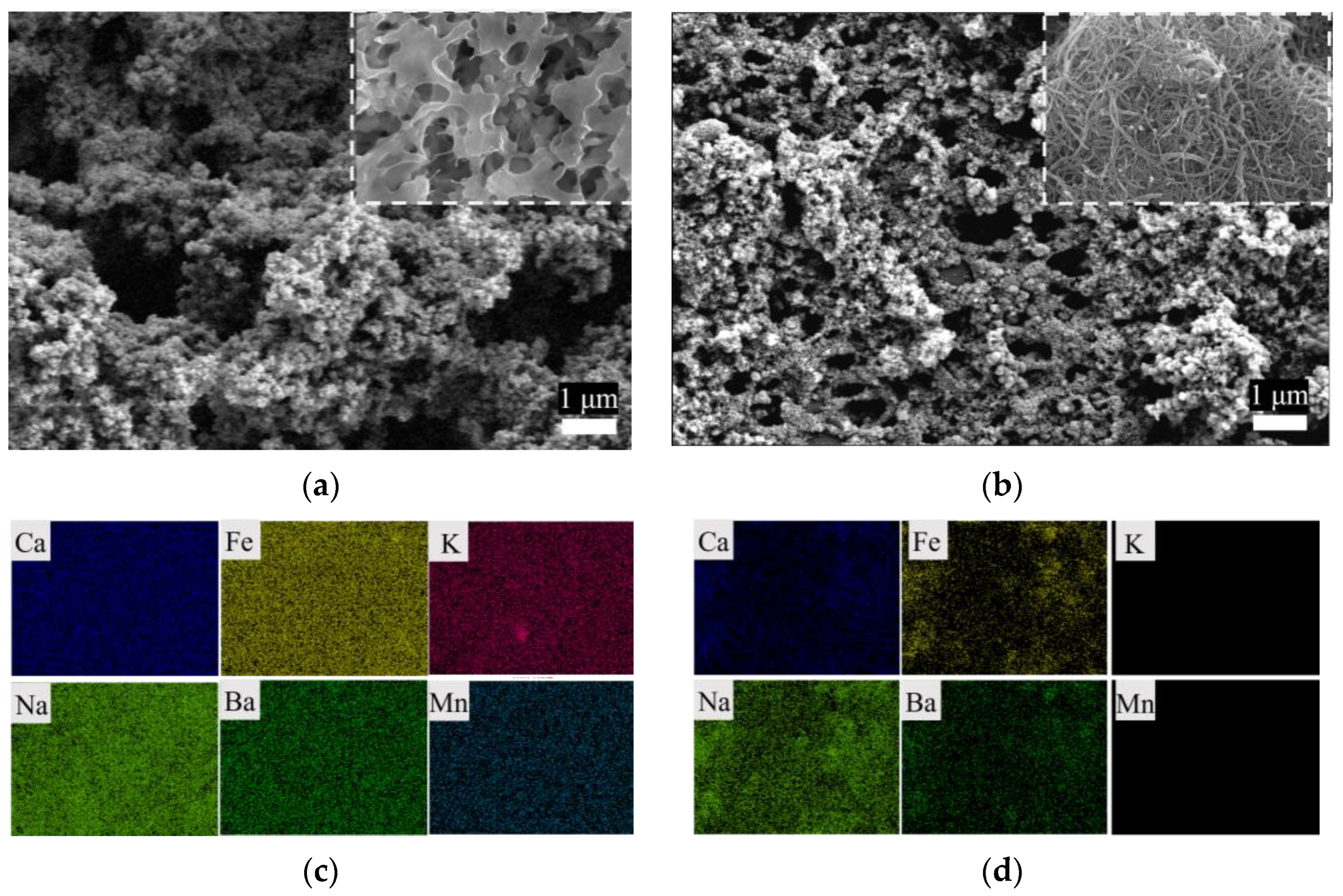
To further explore the foulant, SEM-EDS was used to characterize the morphology and remaining elements on the membrane’s surface, as shown in Figure 5. The cleaned PVDF membrane surface was completely covered with particulates. According to the surface elemental analysis (Figure 5c,d, and Figure S3), the PVDF membrane, ideally composed of 38% C and 59% F [21], was completely covered by foulants consisting of O and Si and inorganic elements such as Ca and Fe. In contrast, the mesh structure of the CNT fiber for the PVDF-CNT-FAS membrane was highly visible, despite the fact that the membrane was also wrapped by particulates. The EDS analysis monitored the elements of C, F, O, and Si originally present in the PVDF-CNT-FAS membrane. Moreover, the presence of Ca, Fe, Na, and Ba on the modified membrane (0.28%, 3.63%, 0.64%, and 2.03%, respectively) was found to be less than those on the PVDF membrane, with the elements of K and Mn not detected. Furthermore, the potential organic foulants on the two hydrophobic membranes were washed using acid and ultrasonication and then characterized and analyzed with fluorescence spectroscopy (Figure S2). The results show that the organic fouling of tryptophan was slightly more obvious on the PVDF membrane than that on PVDF-CNT-FAS. Nevertheless, organic fouling seemed weak on both membranes. Hence, our fouling characterization suggested that the inorganic membrane fouling degree was the major concern in dealing with the real shale gas stream, and the PVDF-CNT-FAS membrane again exhibited better resistance to inorganic foulants than the PVDF membrane. This slippery interface on the CNT layer may lead to a short residence time for the foulants to adhere to the membrane surface, as stated previously in our papers [20,24]. To sum up, benefiting from the introduction of the CNT intermediate layer, the PVDF-CNT-FAS membrane has a better fouling/wetting resistance and permeability.
3.6. Cost-Effectiveness Analysis
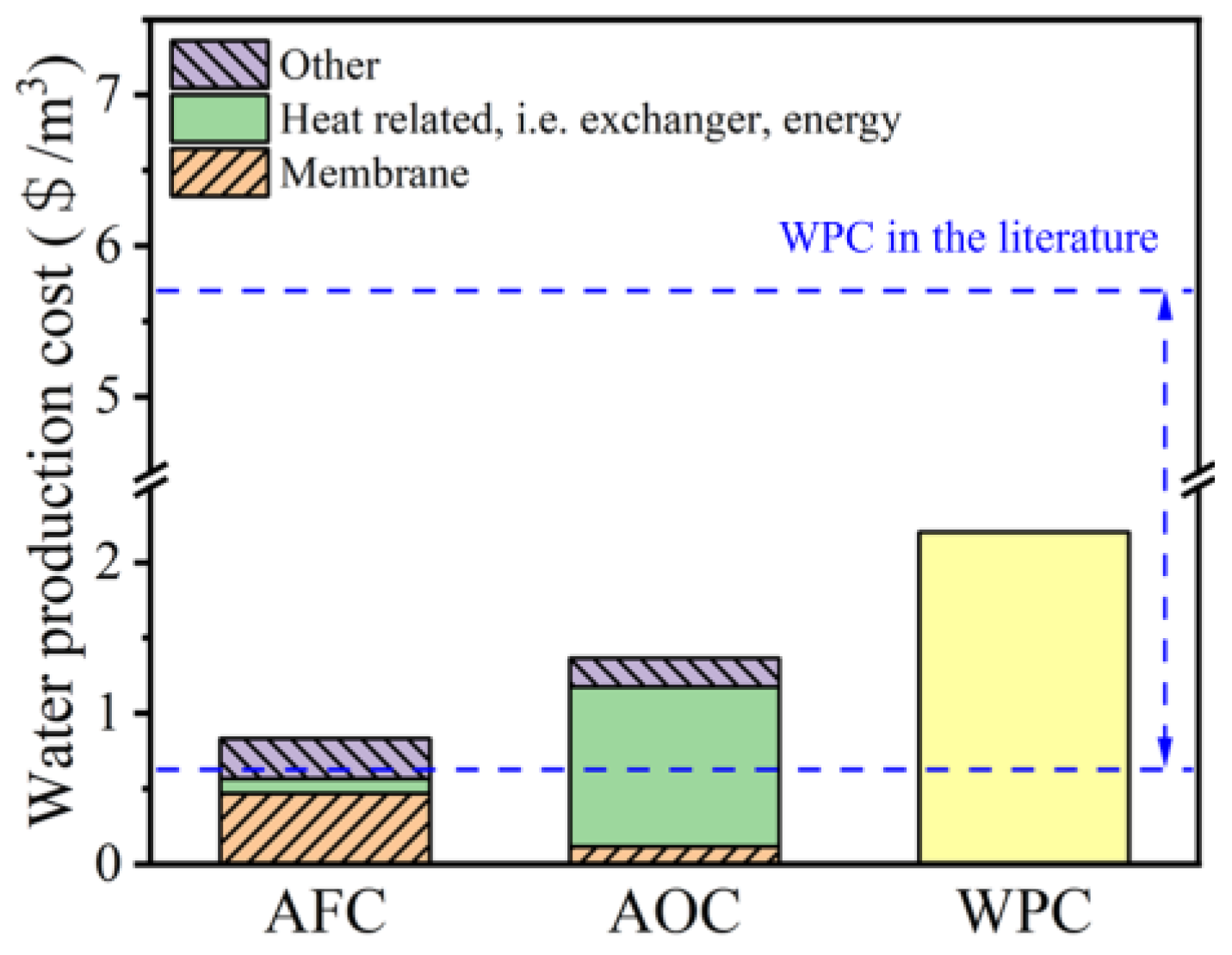
Following the above findings, the total water production cost (WPC) of the PVDF-CNT-FAS membrane in treating real shale gas wastewater was estimated by considering the process design and project evaluation. The fixed production capacity and plant availability factors were 2000 m3/d and 90%, respectively. The other parameters and analytical methods are listed in the supplementary materials. As shown in Figure 6, the WPC was divided into two main components, namely, the annual fixed charges (AFCs) and the annual operating cost (AOC). The AFC was USD 0.83/m3, dominated by the cost of the membrane, pump, and heat exchanger. Specifically, the cost of the heat exchanger and membrane accounted for 67.96% of the AFC at USD 0.1 and 0.47/m3, respectively (Table S2). Compared with the reference data (an AFC of USD 0.29–0.51/m3), the AFC in this work is slightly higher. As illustrated in Figure 6, consistent with the studies of MD in drinking water treatments [40,41], seawater desalination [42], and hypersaline industrial stream treatments [43], our calculated AOC reaches USD 1.36/m3, which is composed mainly of the cost of the heat energy consumption (80.3%). If low-cost waste heat is used instead of steam [40], this value may be further reduced to USD 0.31/m3. Specifically, the cost of membrane replacement accounts for 8.60% of the AOC, with a membrane replacement rate of 20%. In summary, the WPC of USD 2.2/m3 agrees with reported values in the range of USD 0.61–5.7/m3 [10,42], proving the economic feasibility of the PVDF-CNT-FAS membrane in MD applications. The proposed new membrane may compete in the open market in view of better fouling/wetting resistance and permeate quality.
4. Conclusions
Our experiments validated the potential of the PVDF-CNT-FAS membrane to treat real shale gas wastewater in terms of both the permeate side of water quality improvement and membrane fouling alleviation. The PVDF-CNT-FAS membrane achieved 48.2% effluent reduction and 99% salt retention after three cycles of wastewater concentration experiments and 80% flux recovery after the first rinse. In contrast, only 20.5% of the wastewater volume could be reduced by the PVDF membrane, with a lower concentration factor and flux recovery. The permeate with the modified membrane exhibited superior water quality, including a TOC of 10 mg/L, a COD of less than 50 mg/L, and total nitrogen and ammonia nitrogen of less than 20 mg/L, which met the requirements of local wastewater discharge standards well (GB8978-2006). Lower amounts of tryptophan-like contaminants in the permeate were found in both cases, probably due to the volatile property of the organic substances. Nevertheless, the inorganic scaling issue was a concern deserving more attention. Unlike the PVDF membrane, the surface of which was completely covered by particulates of varying inorganic elements, the PVDF-CNT-FAS membrane maintained its fiber network structure of much fewer deposits than the control. Finally, the cost-effectiveness was highlighted for the proposed PVDF-CNT-FAS membrane by analyzing its economic feasibility in potential MD applications. In summary, compared to the control, the CNT-modified membranes increased the permeate quantity and improved water quality, mitigating the fouling and scaling issues thanks to the superhydrophobic and slip-coating layer. The superior performance in dealing with real shale gas wastewater than commercial membranes implied the future potential of this simple modification methodology. Studies further tailoring the materials and verifying their long-term feasibility in concentrating complex wastewater are suggested.
Supplementary Materials
The following supporting information can be downloaded at: https://www.mdpi.com/article/10.3390/w15030439/s1, Figure S1: Water recovery volume and salt retention rate on the permeate side after concentration during the three cycles in MD; Figure S2: Cleaning of organic foulants on membrane surface with acid: (a) PVDF membrane (b) PVDF-CNT-FAS membrane; Figure S3: SEM-EDS coupled determination of fouled membrane (a) PVDF and (b) PVDF-CNT-FAS surface elements; Table S1: Assumption parameters and specific costs in economic analysis; Table S2: Fixed and Operating cost per cubic meter of shale gas wastewater treatment [41,44].
Author Contributions
Investigation, methodology, writing—original draft preparation, formal analysis, Y.W.; visualization, writing—review and editing, H.Z.; writing—review and editing, R.Z.; writing—review and editing, D.W.; writing—review and editing, L.Z.; supervision, writing—review and editing, conceptualization, funding acquisition, L.H. All authors have read and agreed to the published version of the manuscript.
Funding
The authors acknowledge the financial support provided by the National Natural Science Foundation of China (51908083, 52270058), and the Venture and Innovation Support Program for Chongqing Overseas Returnees (CX2018004).
Data Availability Statement
Data will be released upon request.
Conflicts of Interest
The authors declare no conflict of interest.
References
- Tavakkoli, S.; Lokare, O.; Vidic, R.; Khanna, V. Shale gas produced water management using membrane distillation: An optimization-based approach. Resour. Conserv. Recycl. 2020, 158, 104803. [Google Scholar] [CrossRef]
- Boo, C.; Lee, J.; Elimelech, M. Omniphobic Polyvinylidene Fluoride (PVDF) Membrane for Desalination of Shale Gas Produced Water by Membrane Distillation. Environ. Sci. Technol. 2016, 50, 12275–12282. [Google Scholar] [CrossRef]
- Lan, D.; Chen, M.; Liu, Y.; Liang, Q.; Tu, W.; Chen, Y.; Liang, J. Development of Shale Gas in China and Treatment Options for Wastewater Produced from the Exploitation: Sustainability Lessons from the United States. J. Environ. Eng. 2020, 146, 04020103. [Google Scholar] [CrossRef]
- Wang, H.; Lu, L.; Chen, X.; Bian, Y.; Ren, Z.J. Geochemical and microbial characterizations of flowback and produced water in three shale oil and gas plays in the central and western United States. Water Res. 2019, 164, 114942. [Google Scholar] [CrossRef] [PubMed]
- Butkovskyi, A.; Bruning, H.; Kools, S.A.E.; Rijnaarts, H.H.M.; Van Wezel, A.P. Organic Pollutants in Shale Gas Flowback and Produced Waters: Identification, Potential Ecological Impact, and Implications for Treatment Strategies. Environ. Sci. Technol. 2017, 51, 4740–4754. [Google Scholar] [CrossRef]
- Khawaji, A.D.; Kutubkhanah, I.K.; Wie, J.M. Advances in seawater desalination technologies. Desalination 2008, 221, 47–69. [Google Scholar] [CrossRef]
- Li, Y.; Li, M.; Xiao, K.; Huang, X. Reverse osmosis membrane autopsy in coal chemical wastewater treatment: Evidences of spatially heterogeneous fouling and organic-inorganic synergistic effect. J. Clean Prod. 2020, 246, 118964. [Google Scholar] [CrossRef]
- Martinetti, C.R.; Childress, A.E.; Cath, T.Y. High recovery of concentrated RO brines using forward osmosis and membrane distillation. J. Membr. Sci. 2009, 331, 31–39. [Google Scholar] [CrossRef]
- Alkhudhiri, A.; Darwish, N.; Hilal, N. Membrane distillation: A comprehensive review. Desalination 2012, 287, 2–18. [Google Scholar] [CrossRef]
- Yadav, A.; Labhasetwar, P.K.; Shahi, V.K. Membrane distillation using low-grade energy for desalination: A review. J. Environ. Chem. Eng. 2021, 9, 105818. [Google Scholar] [CrossRef]
- Alklaibi, A.M.; Lior, N. Membrane-distillation desalination: Status and potential. Desalination 2005, 171, 111–131. [Google Scholar] [CrossRef]
- Han, L.; Tan, Y.Z.; Netke, T.; Fane, A.G.; Chew, J.W. Understanding oily wastewater treatment via membrane distillation. J. Membr. Sci. 2017, 539, 284–294. [Google Scholar] [CrossRef]
- Rezaei, M.; Warsinger, D.M.; Lienhard, J.H.; Duke, M.C.; Matsuura, T.; Samhaber, W.M. Wetting phenomena in membrane distillation: Mechanisms, reversal, and prevention. Water Res. 2018, 139, 329–352. [Google Scholar] [CrossRef] [PubMed]
- Horseman, T.; Yin, Y.M.; Christie, K.S.S.; Wang, Z.X.; Tong, T.Z.; Lin, S.H. Wetting, Scaling, and Fouling in Membrane Distillation: State-of-the-Art Insights on Fundamental Mechanisms and Mitigation Strategies. ACS EST Eng. 2021, 1, 117–140. [Google Scholar] [CrossRef]
- Warsinger, D.M.; Swarninathan, J.; Guillen-Burrieza, E.; Arafat, H.A.; Lienhard, J.H. Scaling and fouling in membrane distillation for desalination applications: A review. Desalination 2015, 356, 294–313. [Google Scholar] [CrossRef]
- Lin, S.H.; Nejati, S.; Boo, C.; Hu, Y.X.; Osuji, C.O.; Ehmelech, M. Omniphobic Membrane for Robust Membrane Distillation. Environ. Sci. Technol. Lett. 2014, 1, 443–447. [Google Scholar] [CrossRef]
- Eykens, L.; De Sitter, K.; Dotremont, C.; Pinoy, L.; Van der Bruggen, B. Membrane synthesis for membrane distillation: A review. Sep. Purif. Technol. 2017, 182, 36–51. [Google Scholar] [CrossRef]
- Son, M.; Park, H.; Liu, L.; Choi, H.; Kim, J.H.; Choi, H. Thin-film nanocomposite membrane with CNT positioning in support layer for energy harvesting from saline water. Chem. Eng. J. 2016, 284, 68–77. [Google Scholar] [CrossRef]
- Shan, H.; Liu, J.; Li, X.; Li, Y.; Tezel, F.H.; Li, B.; Wang, S. Nanocoated amphiphobic membrane for flux enhancement and comprehensive anti-fouling performance in direct contact membrane distillation. J. Membr. Sci. 2018, 567, 166–180. [Google Scholar] [CrossRef]
- Wang, Y.; Han, M.; Liu, L.; Yao, J.; Han, L. Beneficial CNT Intermediate Layer for Membrane Fluorination toward Robust Superhydrophobicity and Wetting Resistance in Membrane Distillation. ACS Appl. Mater. Interfaces 2020, 12, 20942–20954. [Google Scholar] [CrossRef]
- Robbins, C.A.; Yin, Y.; Hanson, A.J.; Blotevogel, J.; Borch, T.; Tong, T. Mitigating membrane wetting in the treatment of unconventional oil and gas wastewater by membrane distillation: A comparison of pretreatment with omniphobic membrane. J. Membr. Sci. 2022, 645, 120198. [Google Scholar] [CrossRef]
- Du, X.; Zhang, Z.; Carlson, K.H.; Lee, J.; Tong, T. Membrane fouling and reusability in membrane distillation of shale oil and gas produced water: Effects of membrane surface wettability. J. Membr. Sci. 2018, 567, 199–208. [Google Scholar] [CrossRef]
- Gethard, K.; Sae-Khow, O.; Mitra, S. Water desalination using carbon-nanotube-enhanced membrane distillation. ACS Appl. Mater. Interfaces 2011, 3, 110–114. [Google Scholar] [CrossRef] [PubMed]
- Han, M.; Dong, T.; Hou, D.; Yao, J.; Han, L. Carbon nanotube based Janus composite membrane of oil fouling resistance for direct contact membrane distillation. J. Membr. Sci. 2020, 607, 118078. [Google Scholar] [CrossRef]
- Han, M.; Wang, Y.; Yao, J.; Liu, C.; Chew, J.W.; Wang, Y.; Dong, Y.; Han, L. Electrically conductive hydrophobic membrane cathode for membrane distillation with super anti-oil-fouling capability: Performance and mechanism. Desalination 2021, 516, 115199. [Google Scholar] [CrossRef]
- Zheng, R.; Chen, Y.; Wang, J.; Song, J.; Li, X.-M.; He, T. Preparation of omniphobic PVDF membrane with hierarchical structure for treating saline oily wastewater using direct contact membrane distillation. J. Membr. Sci. 2018, 555, 197–205. [Google Scholar] [CrossRef]
- Chen, Y.; Lu, K.J.; Chung, T.-S. An omniphobic slippery membrane with simultaneous anti-wetting and anti-scaling properties for robust membrane distillation. J. Membr. Sci. 2020, 595, 117572. [Google Scholar] [CrossRef]
- Gu, J.; Xiao, P.; Huang, Y.; Zhang, J.; Chen, T. Controlled functionalization of carbon nanotubes as superhydrophobic material for adjustable oil/water separation. J. Mater. Chem. A 2015, 3, 4124–4128. [Google Scholar] [CrossRef]
- Wang, S.; Liang, S.; Liang, P.; Zhang, X.; Sun, J.; Wu, S.; Huang, X. In-situ combined dual-layer CNT/PVDF membrane for electrically-enhanced fouling resistance. J. Membr. Sci. 2015, 491, 37–44. [Google Scholar] [CrossRef]
- Kharraz, J.A.; Farid, M.U.; Khanzada, N.K.; Deka, B.J.; Arafat, H.A.; An, A.K. Macro-corrugated and nano-patterned hierarchically structured superomniphobic membrane for treatment of low surface tension oily wastewater by membrane distillation. Water Res. 2020, 174, 115600. [Google Scholar] [CrossRef]
- Christie, K.S.S.; Yin, Y.; Lin, S.; Tong, T. Distinct Behaviors between Gypsum and Silica Scaling in Membrane Distillation. Environ. Sci. Technol. 2019, 54, 568–576. [Google Scholar] [CrossRef] [PubMed]
- Yan, Z.; Zhu, Z.; Chang, H.; Fan, G.; Wang, Q.; Fu, X.; Qu, F.; Liang, H. Integrated membrane electrochemical reactor-membrane distillation process for enhanced landfill leachate treatment. Water Res. 2023, 230, 119559. [Google Scholar] [CrossRef] [PubMed]
- Shrestha, N.; Chilkoor, G.; Wilder, J.; Ren, Z.J.; Gadhamshetty, V. Comparative performances of microbial capacitive deionization cell and microbial fuel cell fed with produced water from the Bakken shale. Bioelectrochemistry 2018, 121, 56–64. [Google Scholar] [CrossRef] [PubMed]
- Qi, L.; Qihang, X.; Zejun, Z.; Yong, H.; Yi, Z.; Shibin, X. Combined effect of ozone and PTFE membrane on treating shale gas produced wastewater in Fuling Shale Gas Field. Desalin. Water Treat. 2019, 140, 183–188. [Google Scholar] [CrossRef] [Green Version]
- Kim, S.; Lee, D.W.; Cho, J. Application of direct contact membrane distillation process to treat anaerobic digestate. J. Membr. Sci. 2016, 511, 20–28. [Google Scholar] [CrossRef]
- Chen, C.; Dong, T.; Han, M.; Yao, J.; Han, L. Ammonium recovery from wastewater by Donnan Dialysis: A feasibility study. J. Clean Prod. 2020, 265, 121838. [Google Scholar] [CrossRef]
- Chen, C.; Dai, Z.; Li, Y.; Zeng, Q.; Yu, Y.; Wang, X.; Zhang, C.; Han, L. Fouling-free membrane stripping for ammonia recovery from real biogas slurry. Water Res. 2023, 229, 119453. [Google Scholar] [CrossRef]
- Li, F.; Huang, J.; Xia, Q.; Lou, M.; Yang, B.; Tian, Q.; Liu, Y. Direct contact membrane distillation for the treatment of industrial dyeing wastewater and characteristic pollutants. Sep. Purif. Technol. 2018, 195, 83–91. [Google Scholar] [CrossRef]
- Cho, H.; Choi, Y.; Lee, S. Effect of pretreatment and operating conditions on the performance of membrane distillation for the treatment of shale gas wastewater. Desalination 2018, 437, 195–209. [Google Scholar] [CrossRef]
- Han, L.; Xiao, T.; Tan, Y.Z.; Fane, A.G.; Chew, J.W. Contaminant rejection in the presence of humic acid by membrane distillation for surface water treatment. J. Membr. Sci. 2017, 541, 291–299. [Google Scholar] [CrossRef]
- Al-Obaidani, S.; Curcio, E.; Macedonio, F.; Di Profio, G.; Ai-Hinai, H.; Drioli, E. Potential of membrane distillation in seawater desalination: Thermal efficiency, sensitivity study and cost estimation. J. Membr. Sci. 2008, 323, 85–98. [Google Scholar] [CrossRef]
- Kesieme, U.K.; Milne, N.; Aral, H.; Cheng, C.Y.; Duke, M. Economic analysis of desalination technologies in the context of carbon pricing, and opportunities for membrane distillation. Desalination 2013, 323, 66–74. [Google Scholar] [CrossRef] [Green Version]
- Tavakkoli, S.; Lokare, O.R.; Vidic, R.D.; Khanna, V. A techno-economic assessment of membrane distillation for treatment of Marcellus shale produced water. Desalination 2017, 416, 24–34. [Google Scholar] [CrossRef]
- Khayet, M. Solar desalination by membrane distillation: Dispersion in energy consumption analysis and water production costs (a review). Desalination 2013, 308, 89–101. [Google Scholar] [CrossRef]
Figure 1.
The normalized flux and salt rejection rate in the treatment of simulated shale gas wastewater. The MD experiments were conducted using simulated wastewater (1 M NaCl, 0.05 mM SDS with 160 ppm mineral oil) in cycles of 20 h. The membrane was rinsed with water at the end of each cycle until the washing solution conductivity of both the feed and permeate side dropped to 10 μS/cm.

Figure 2.
The normalized flux and concentration coefficient of the concentration of the real shale gas wastewater in MD, with initial fluxes of 23.6 and 22.92 kg/(m2∙h) for the PVDF and PVDF-CNT-FAS membranes, respectively.
Figure 2.
The normalized flux and concentration coefficient of the concentration of the real shale gas wastewater in MD, with initial fluxes of 23.6 and 22.92 kg/(m2∙h) for the PVDF and PVDF-CNT-FAS membranes, respectively.

Figure 3.
Permeate water quality at the end of each cycle in terms of the (a) COD, (b) TOC, (c) TN, and (d) ammonia. The dashed line denotes the corresponding limit value for each parameter according to the local standard (GB8978-2006).
Figure 3.
Permeate water quality at the end of each cycle in terms of the (a) COD, (b) TOC, (c) TN, and (d) ammonia. The dashed line denotes the corresponding limit value for each parameter according to the local standard (GB8978-2006).

Figure 4.
Three-dimensional fluorescence analysis for the (a) real shale gas wastewater and permeates from the (b) PVDF membrane and (c) PVDF-CNT-FAS membrane.
Figure 4.
Three-dimensional fluorescence analysis for the (a) real shale gas wastewater and permeates from the (b) PVDF membrane and (c) PVDF-CNT-FAS membrane.

Figure 5.
SEM-EDS images of the (a,c) PVDF and (b,d) PVDF-CNT-FAS membranes. The top-inserted image refers to the virgin membrane.
Figure 5.
SEM-EDS images of the (a,c) PVDF and (b,d) PVDF-CNT-FAS membranes. The top-inserted image refers to the virgin membrane.

Figure 6.
The annual fixed cost (AFC), annual operating cost (AOC), and total water production cost (WPC, sum of the AFC and AOC) estimated for the shale gas wastewater treatment using the PVDF-CNT-FAS membrane in this study, including a section for the membrane, heat exchange or thermal energy, and other expenses. The cost analysis for the PVDF membrane is not provided considering its deteriorated permeate quality compared with the local standard.


Table 1.
Water quality characteristics of shale gas wastewater.
| Zeta Potential (mv) | Conductivity (mS/cm) | TDS (g/L) | TOC (mg/L) | TN (mg/L) | COD (mg/L) | NH4+ (mg/L) | pH | NTU |
| −4.7 | 41.4 | 21.5 | 372 | 153 | 1921 | 131 | 7.2 | 82 |
| Na (mg/L) | K (mg/L) | Ca (mg/L) | Mg (mg/L) | Ba (mg/L) | Fe (mg/L) | Mn (mg/L) | Cl (mg/L) | Si (mg/L) |
| 360,005 | 778 | 6749 | 30,850 | 4781 | 14,076 | 41 | 30,647 | 271,206 |
Table 2.
Basic characteristics of the PVDF and PVDF-CNT-FAS membranes.
| Characteristic | PVDF | PVDF-CNT-FAS |
|---|---|---|
| Thickness δ (μm) | 125 ± 2 | 140 ± 6 |
| Pore diammater r (μm) | 0.22 ± 0.006 | 0.18 ± 0.003 |
| Slip angle θ0 (°) | >10° | <5° |
| Water contact angle θ1 (°) | 124 ± 3 | 180 |
| Mineral oil contact angle θ2 (°) | 42 ± 6 | 103 ± 2 |
| SEM image of the membrane’s plain surface |  |  |
| SEM image of the membrane’s cross-section |  |  |
Disclaimer/Publisher’s Note: The statements, opinions and data contained in all publications are solely those of the individual author(s) and contributor(s) and not of MDPI and/or the editor(s). MDPI and/or the editor(s) disclaim responsibility for any injury to people or property resulting from any ideas, methods, instructions or products referred to in the content. |
© 2023 by the authors. Licensee MDPI, Basel, Switzerland. This article is an open access article distributed under the terms and conditions of the Creative Commons Attribution (CC BY) license (https://creativecommons.org/licenses/by/4.0/).
Share and Cite
MDPI and ACS Style
Wang, Y.; Zhang, H.; Zhao, R.; Wang, D.; Zhou, L.; Han, L. Desalinating Real Shale Gas Wastewater by Membrane Distillation: Performance and Potentials. Water 2023, 15, 439. https://doi.org/10.3390/w15030439
AMA Style
Wang Y, Zhang H, Zhao R, Wang D, Zhou L, Han L. Desalinating Real Shale Gas Wastewater by Membrane Distillation: Performance and Potentials. Water. 2023; 15(3):439. https://doi.org/10.3390/w15030439
Chicago/Turabian StyleWang, Yuting, Haoquan Zhang, Ruixue Zhao, Die Wang, Lu Zhou, and Le Han. 2023. "Desalinating Real Shale Gas Wastewater by Membrane Distillation: Performance and Potentials" Water 15, no. 3: 439. https://doi.org/10.3390/w15030439
Note that from the first issue of 2016, this journal uses article numbers instead of page numbers. See further details here.