1. Introduction
The equilibrium of the world’s river systems is determined by the scouring and sedimentation of their flow paths [
1,
2,
3]. However, the construction of a dam on a river’s flow path can significantly interrupt the river’s flow, thus leading to decreased stream velocity and prominent sediment accumulation in the reservoir [
4]. Reservoir sedimentation can lead to several problems, including decreased reservoir life and flood volume control, obstructions of flow irrigation and intake points of the hydropower system, damage to tunnels and turbines, and undesirable environmental impacts [
5,
6]. Several methods, such as flushing [
7,
8] sediment bypass [
9], venting of density currents [
10], and hydrosuction [
11,
12,
13], have been developed to address these issues.
Using the hydrosuction siphon system, deposited sediments are removed downstream from reservoirs through the suction pipe based on the effective water head. The pressure for suction deposition is represented by the difference in the water level between upstream and downstream.
The most significant advantage of the hydrosuction technology is that it can be placed manually and moved to any reservoir region [
14]. The inlet of the suction pipe is relocated using a floating barge. As a result, sediment removal can be performed on a large scale. It should be noted that the flow transmission pipes of the hydrosuction system inside dam reservoirs are composed of flexible materials to allow input movements. Rigid pipes are also used on the outside of the reservoir and downstream of the dam. This method, which does not require energy, is environmentally compatible due to the controllable amount of outlet sediments and sediment transmission through the downstream river, and it also has a low operating cost [
1,
5].
Many studies have been conducted on sediment removal through the hydrosuction method. For instance, successful applications of the hydrosuction sediment removal method were observed in several practical projects [
11,
14]. A previous study investigated noncohesive sediment using dimensional analysis and further proposed an equation for scouring hole topography [
15].
In one study, scour hole geometry was analyzed using different sediment types by suctioning a vertical tube above each sediment’s surface layer [
16]. As reported in the study, after 75 to 90 min, the scour hole reached the equilibrium size, i.e., no particle movement was observed within the scour hole.
Another study focused on the critical height of the inlet above the particle surface layer and the theoretical flow rate in the tube head as a sink [
12]. In the study, the forces acting on particle grains were separated into two components: force generated by seepage flow and shear force produced in the sediment’s boundary layers. It was found that the shear stress in the sediment layers did not affect particle movements.
Another paper studied the relationship between the equilibrium conditions of the scour hole properties [
13]. The parameters tested for their hydrosuction system were the diameter of the suction tube and the point of the inlet from the bed.
Several studies found that the absence of the vortex below the suction point favors the sediment removal efficiency [
13,
17]. For instance, Ref [
17] studied the effect of the vortex created by an external pump on the performance of the hydrosuction system; it was observed that the vortex hydrosuction (VHS) increased the geometry of the scour hole.
In line with the above, the main objective of this study is to enhance the performance of the hydrosuction sediment removal (HSSR) system through the installation of specialized fan blades to create a vortex. The effects of the fan blade angles, height of the suction point, and effective head-on sediment removal were examined as the parameters in this study. The novelty of the paper is the use of fan blades without external power to generate the vortex.
2. Experimental and Methods
2.1. Experimental Setup
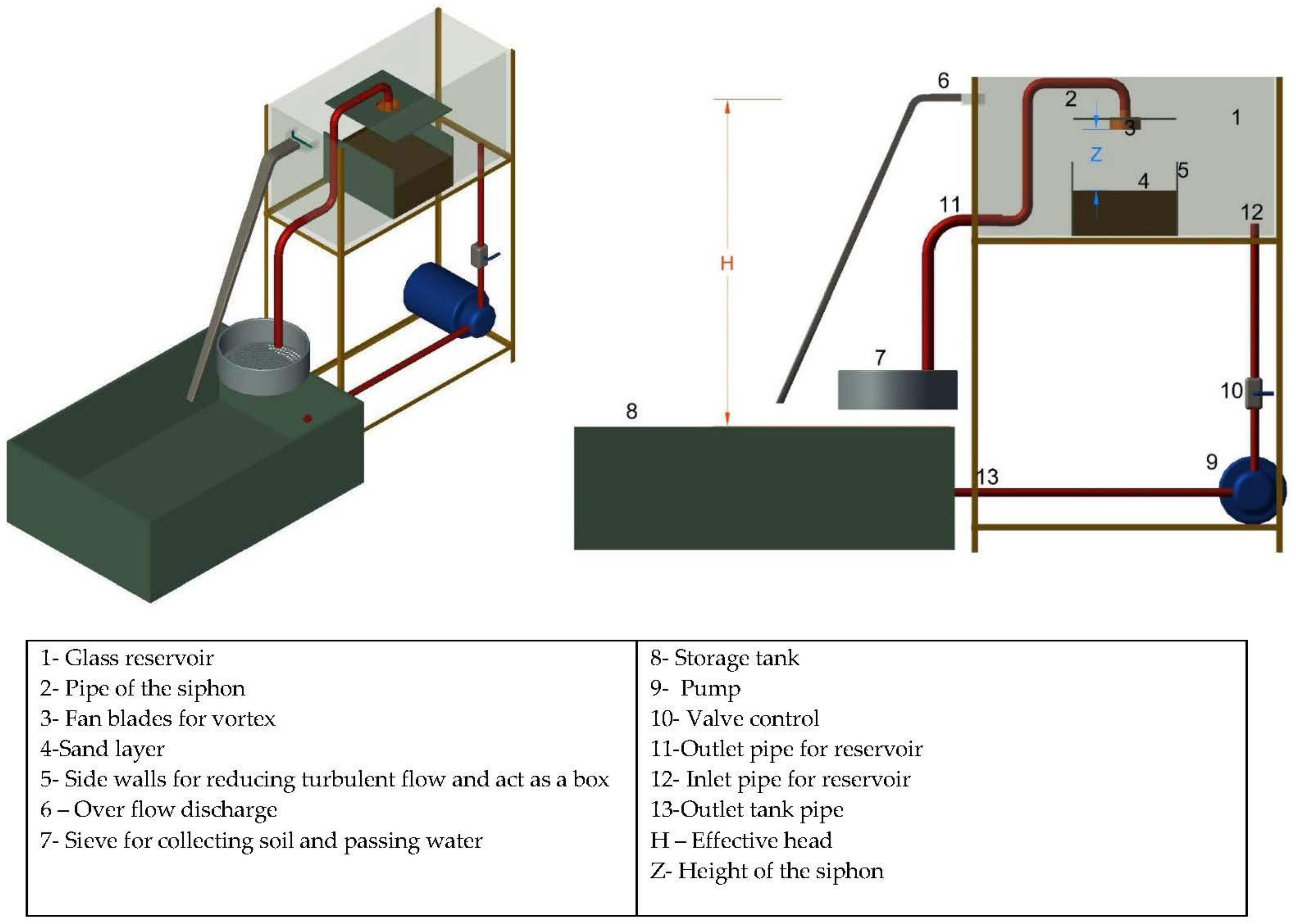
A laboratory study was conducted in the state’s key hydraulic laboratory located at Universiti Sains Malaysia (USM) to gain insights into the effects of the geometric factors of the hydrosuction system on its performance. A new device was developed using a tank model with the dimensions of 1200 cm (L) × 50 cm (W) × 60 cm (H) and 10 mm glass wall thickness to be used to generate a vortex for increasing the hydrosuction sediment removal performance. A 3 cm diameter hole was drilled in the side of the tank model, and a valve was added to the hole for water collection from the model. In the first 20 cm of the model’s top, galvanized iron with 2 mm thickness, 50 cm length, and 30 cm height was installed to reduce the turbulent entrance flow. The collected water was stored in a galvanized iron tank with the dimensions of 200 cm × 70 cm × 70 cm and 2 mm wall thickness. The schematic diagram of the reservoir from the laboratory tank model is shown in
Figure 1.
Additionally, a glass box (50 cm × 50 cm × 30 cm) was developed with an open top where the siphon was installed with fan blades.
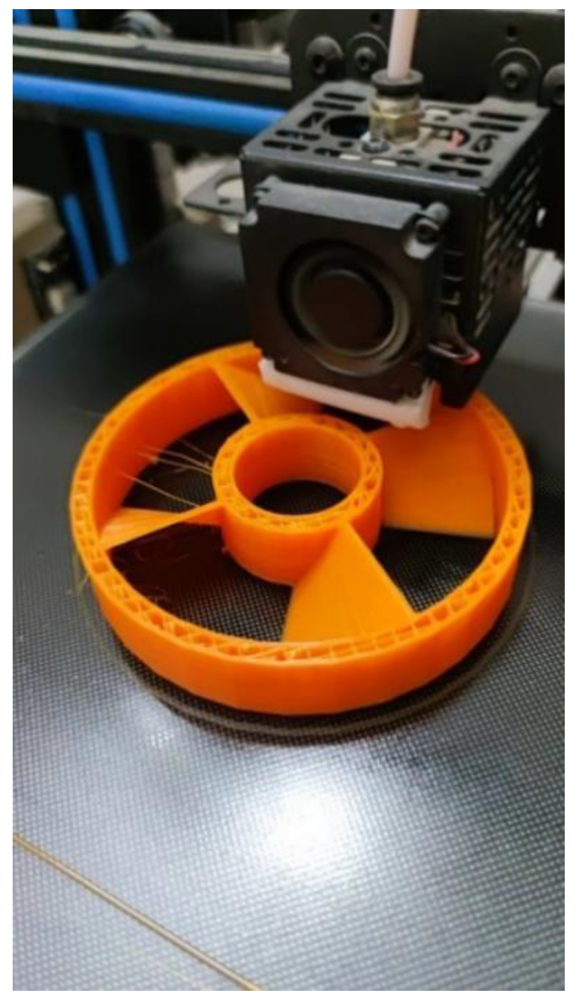
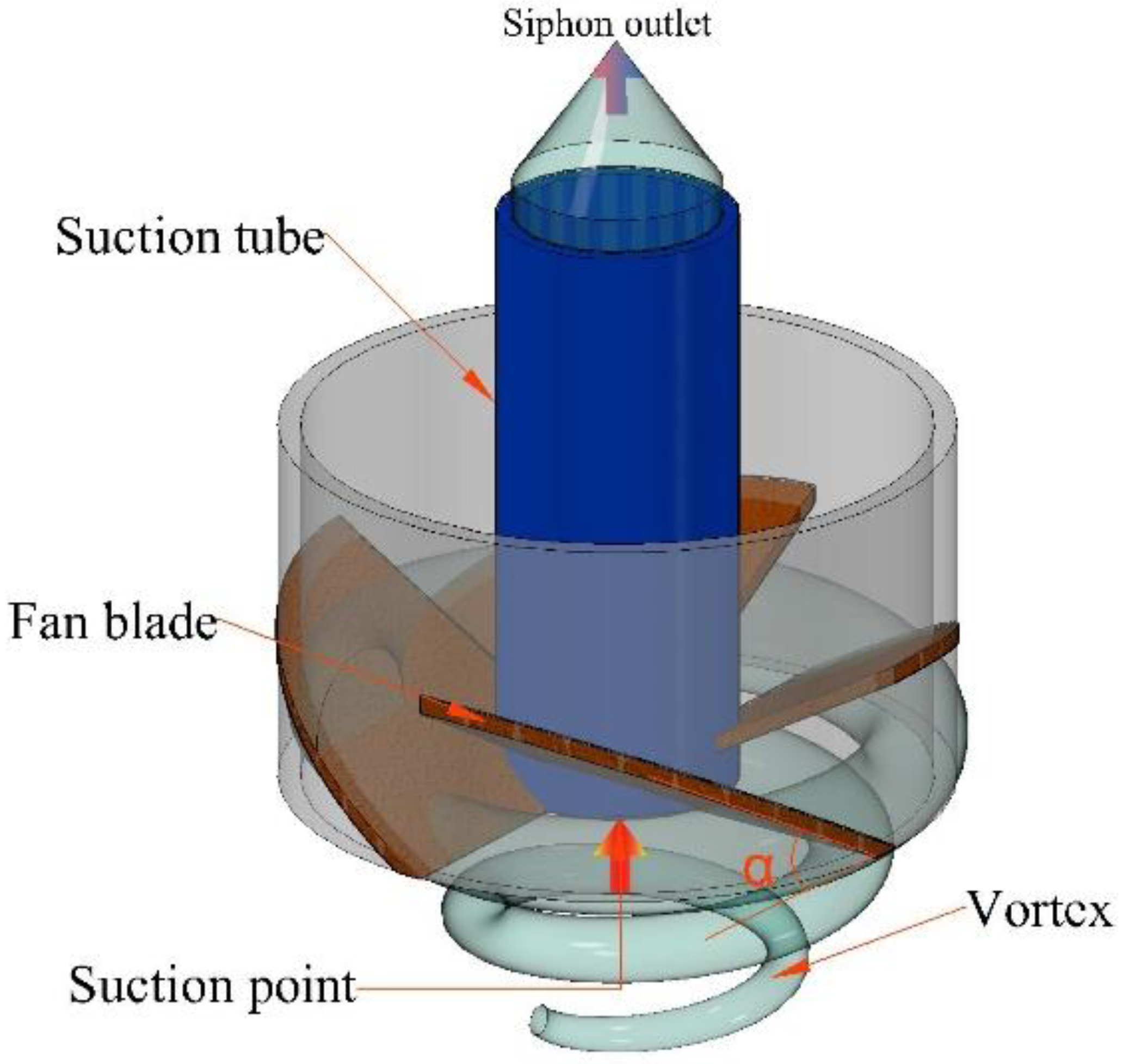
Figure 2 shows the three-dimensional (3D) printed model used to create the physical model with fan blades that would practically rotate horizontally. The details of the model are shown in
Figure 3.
2.2. Experimental Conditions
As shown in
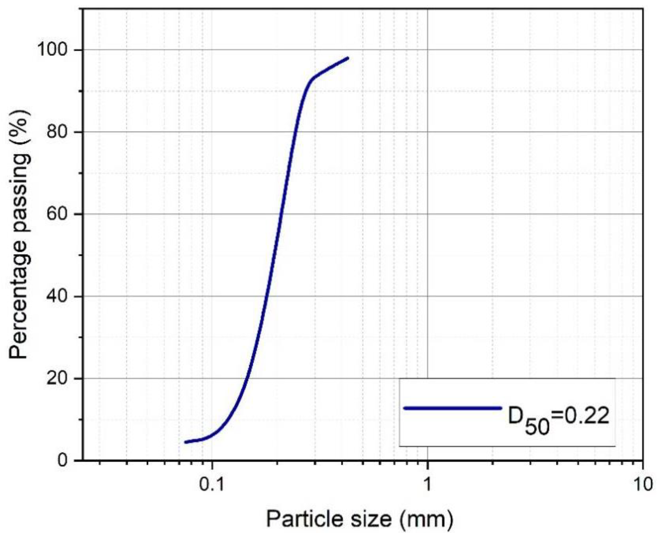
Table 1, approximately 33 tests were conducted to evaluate the characteristics of the scour hole (i.e., depth, diameter, weight of particles, and fan blade angles) for different parameters of the FBHSSR system. The test series from T1-0-0 to T1-0-‘T’-6 was used for the standard HSSR method (as the reference experiment), and the test series from T 2-60°-0 to T 4-30°-‘T’6 was used for the complex FBHSSR system. The diameter of the suction siphon (D) was set at 27.5 mm. The suction siphon was connected with a steel bar and fixed to the sides of the reservoir for adjusting its perpendicular placement during the tests. At the bottom of the reservoir model, washed sand with 18 cm thickness was used as the deposit. Other physical characteristics used were as follows: median size of the sediment particles, i.e., D50 (0.22 mm), mass density of the sediment (2.3 g/cm
3), the uniformity coefficient (2.17), and the curvature coefficient (0.017), as shown in
Figure 4.
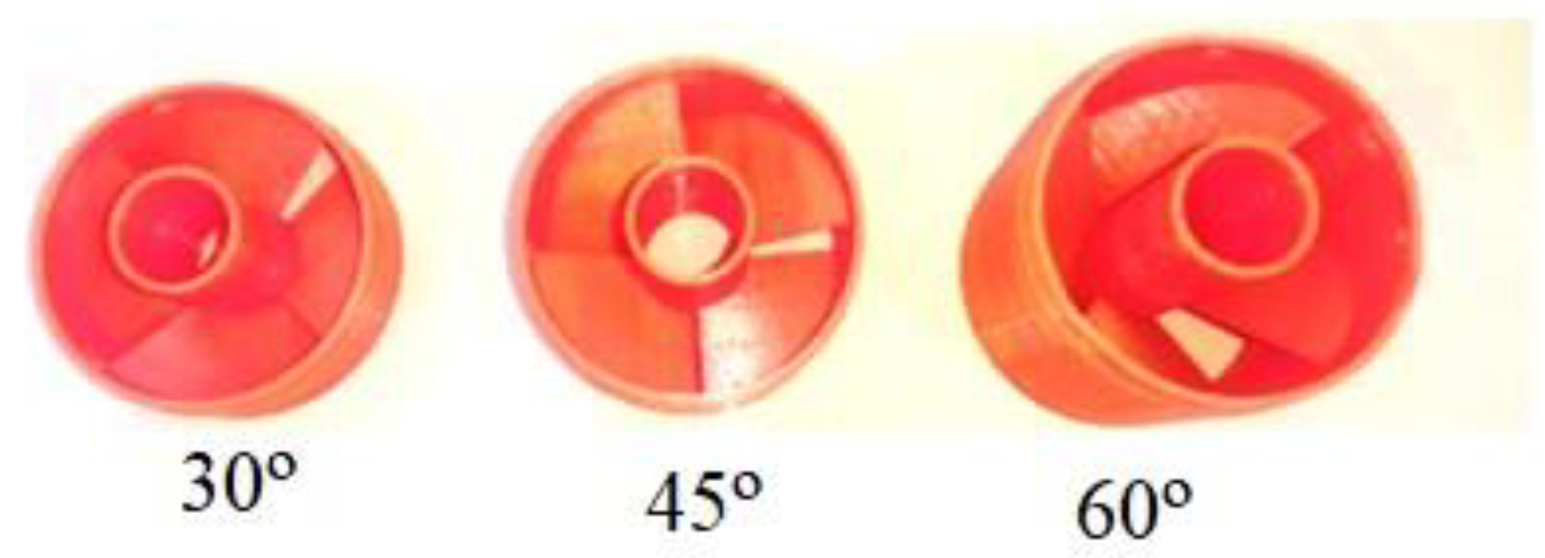
Three parameters for the HSSR system and four parameters for the FBHSSR system were analyzed in this study. The studied parameters include the effective head (H), the height of the suction pipe from the sand surface layer (Z), and the test period (T). These parameters were applied for both the HSSR and FBHSSR systems. The tests of the FBHSSR model included an additional parameter, the fan blade angles (α), as shown in
Figure 5.
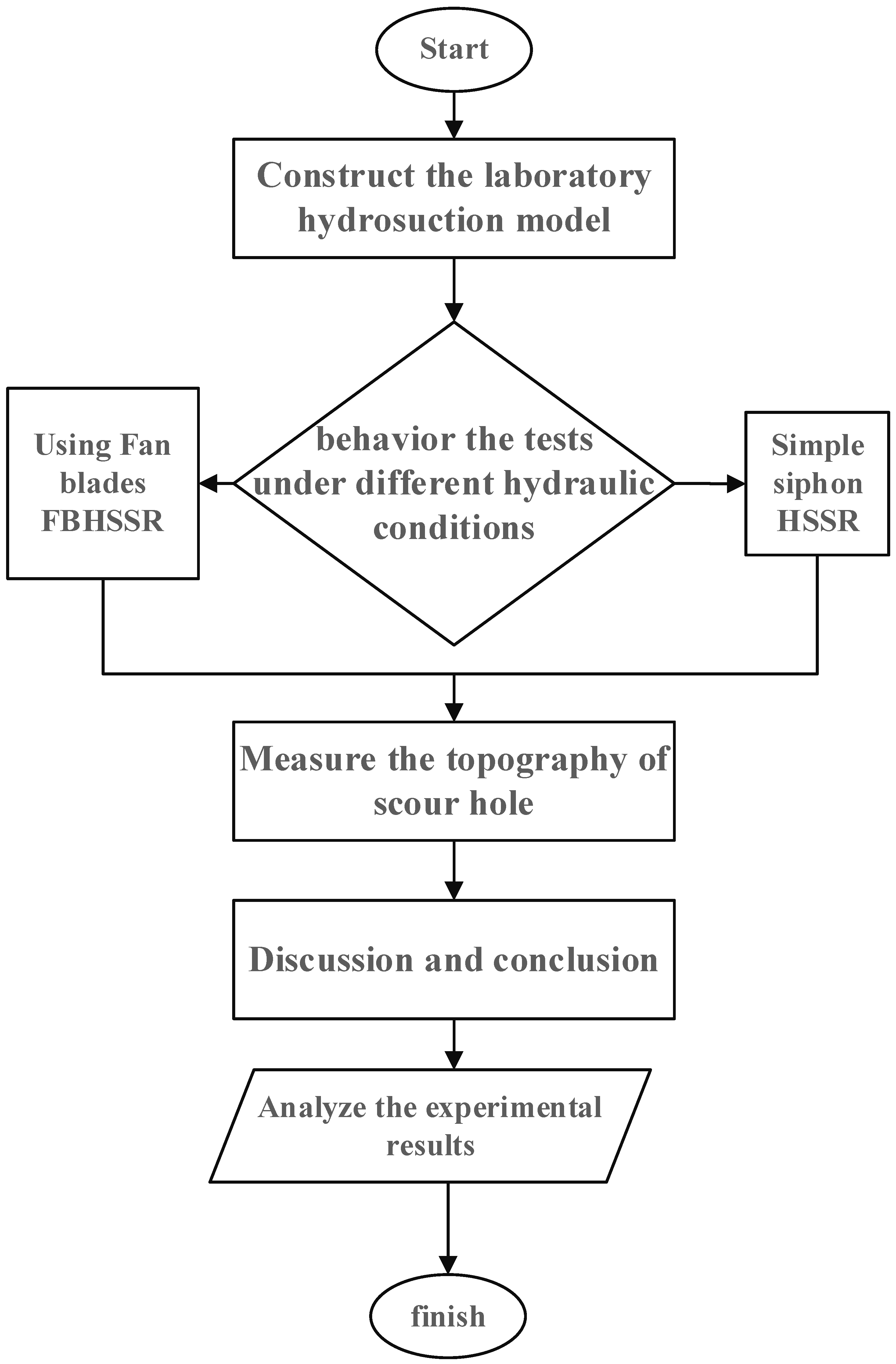
2.3. Experimental Procedure
A collection of soil was deposited into the tank until the surface layer reached 18 cm. Then, the soil surface was smoothed using a wooden planer. Initially, the hydrosuction system was selected based on the conditions of each HSSR and FBHSSR test. Then, the system was installed and secured to prevent movements. Next, the tank was filled with water progressively using a pump (Q max = 8.5 L/S) to prohibit undesirable erosion of the soil surface until the excessive water was removed from the side opening in order to create a constant water head for each test. Finally, the hydrosuction system was installed with an open outlet valve in the suction pipe. The run time was set at 15 min since the effectively removed particles were conditioned over this period [
17,
18].
Upon test completion, sediment particles were removed and collected using the suction siphon. The drainage point at the bottom of the reservoir is for water to be withdrawn from the hole. The geometry of the induced scour hole was measured using a digital point gauge with a precision of 0.01 mm. Then, the collected sediments were dried in an oven and weighed with an accuracy of 0.01 g.
Figure 6 shows the flow chart of the testing process.
3. Dimensional Analysis
Dimensional analysis on the parameters of the FBHSSR system was performed using the Buckingham (
) method [
19,
20]. The weight of sediments removed (
SR) by the suction flow is defined as the method performance indicator. The characteristic parameters included for the analysis were water density and viscosity (
ρw and
μ), gravity acceleration (
g), hole diameter (
R), hole depth (
E), diameter of the fan blades (
Df), diameter of the suction pipe (
D), horizontal angle of the fan blades (
α), average velocity of the suction pipe flow (
V), particle density (
ρs), particle median size (
D50), and inlet height (
Z). These parameters are shown in the following Function (1):
According to the method performance indicator, Equation (1) can be written as follows (2):
where
f1 is an unknown function. Using the Buckingham (
) method, the basic parameters considered for the analysis were
, which resulted in the following Equation (3) with dimensionless variables:
where
Gs is the specific gravity of the particles, and
are the Froude (
Fr) and Reynolds (
Re) numbers, respectively. Therefore, Equation (2) can be rewritten as follows (4):
The
Re number reflected the viscosity effects [
13]. Turbulent flows have low viscosity effects [
21]. Both
variables are constant values. The
Re and constant numbers were neglected in the present study. Therefore, Equation (4) becomes (5):
4. Results and Discussion
The parameters of the performance of the HSSR and FBHSSR systems were investigated in this study. The analysis results of the studied parameters are discussed in detail below.
4.1. Effects of the Fan Blade Angles on the System’s Performance
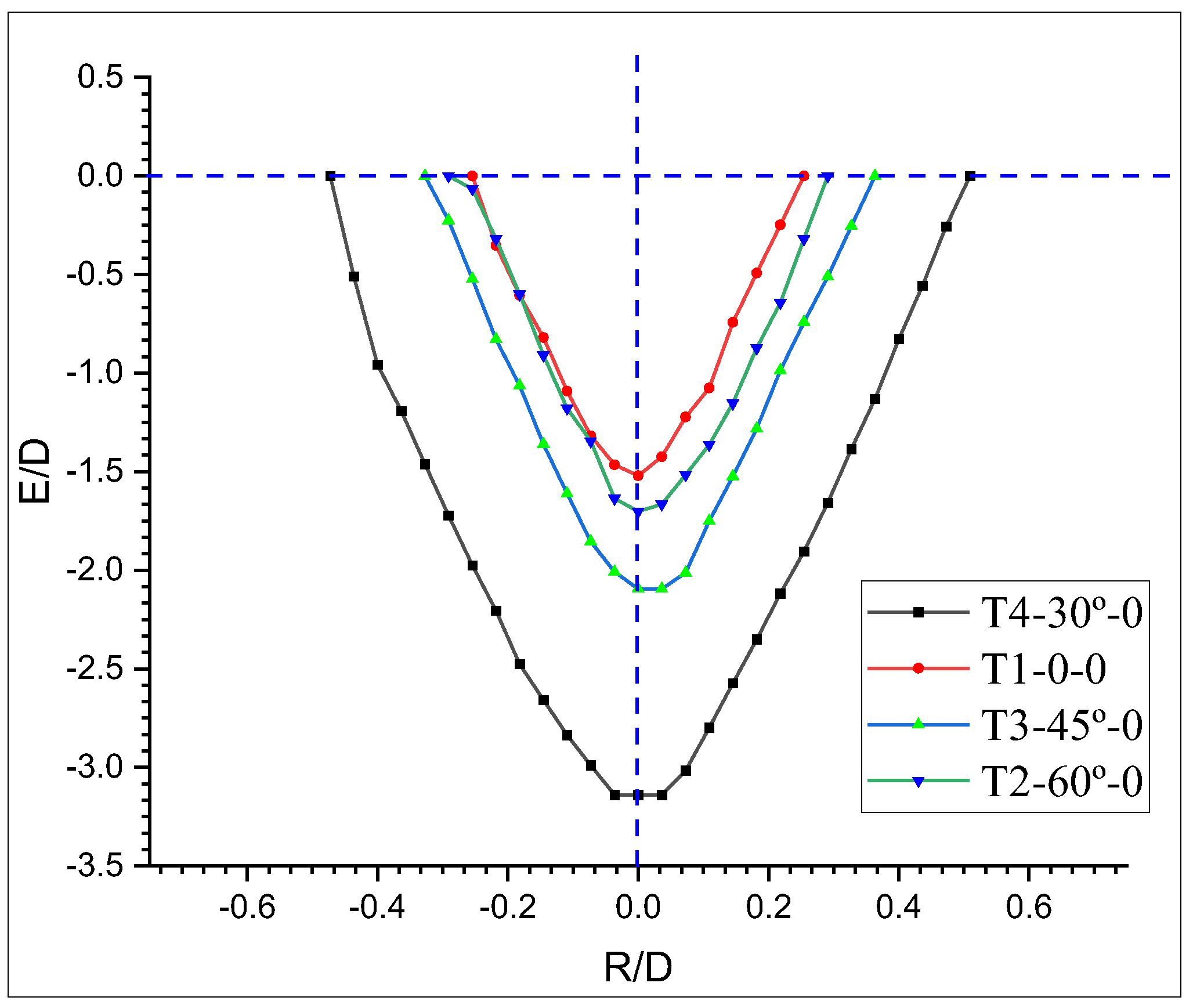
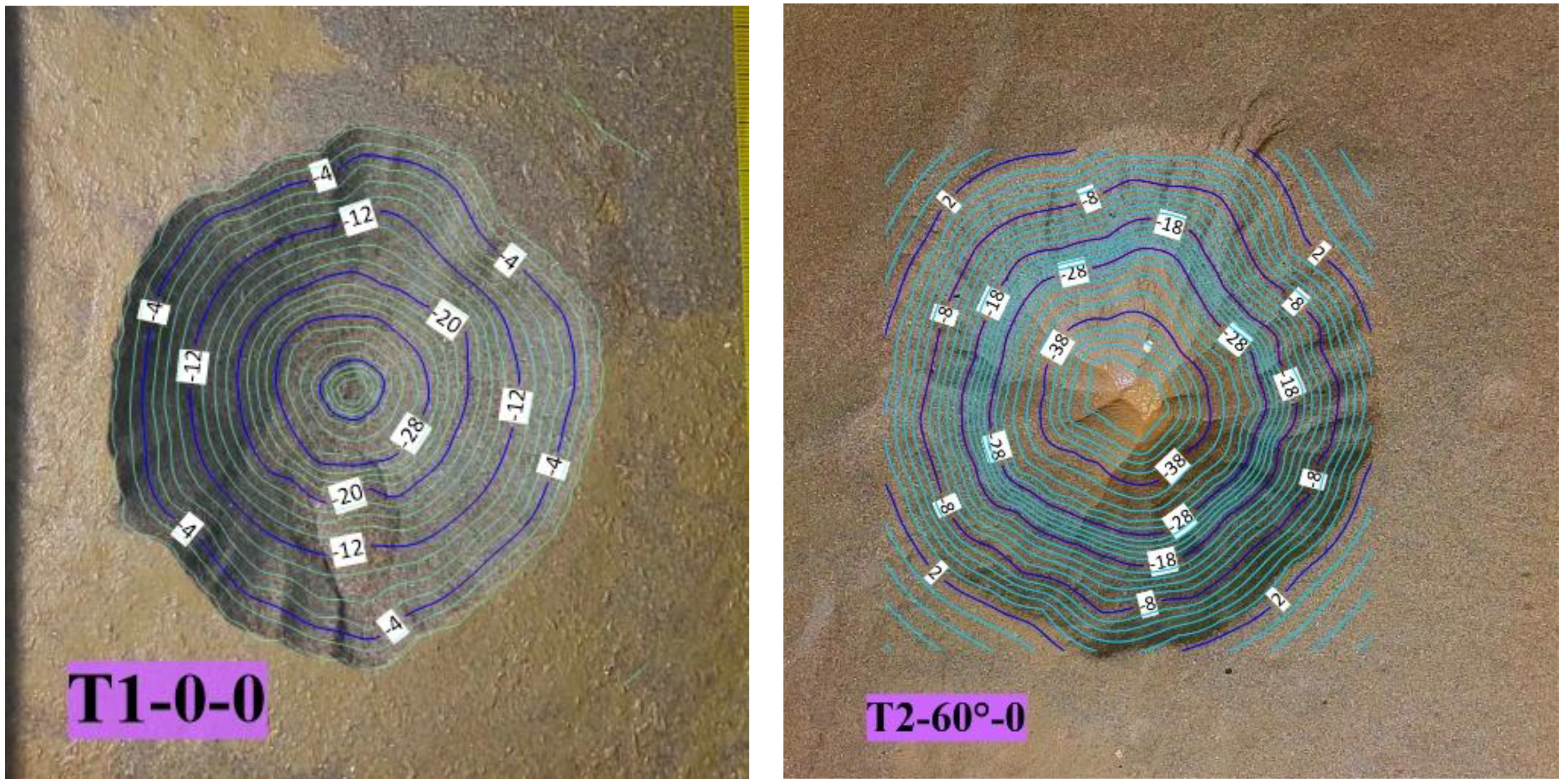
Three different angles were used to investigate the effects of the vortex on the scour hole dimensions for the FBHSSR system.
Figure 7 and
Figure 8 illustrated the effects of the fan blade angles on the geometric characteristics of the scour hole for the system. The maximum values of the E/D and R/D variables were recorded at
, indicating that this is the optimal angle of the hydrosuction system under the experimental conditions in this study.
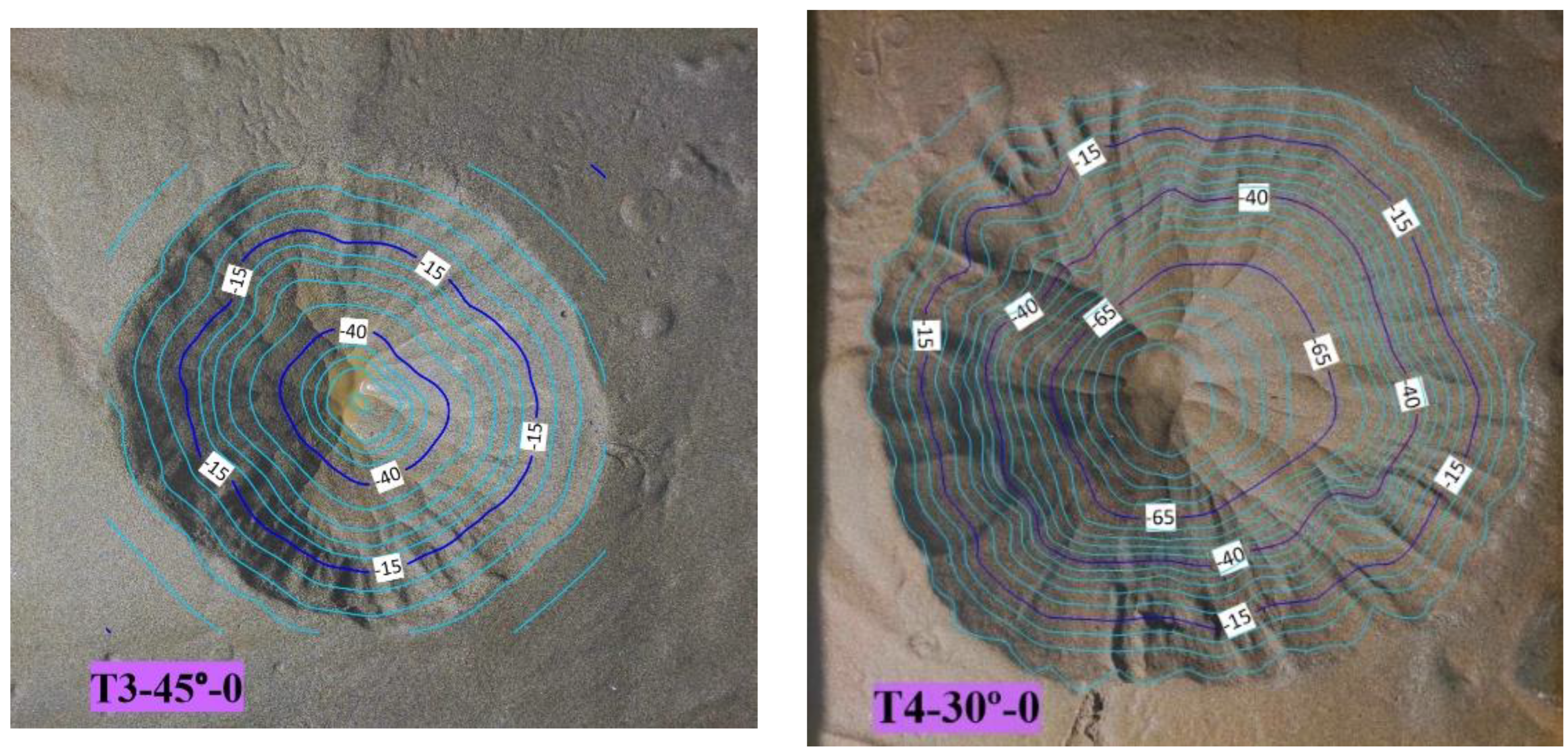
In addition, by using the fan blades with a 30° angle, the maximum scour hole depth and diameter increased by 206% and 200%, respectively. Moreover, the scour hole depth and diameter increased by 137% and 135%, respectively, when the fan blade angle was 45°, and by 112% and 114% when the angle was 60°.
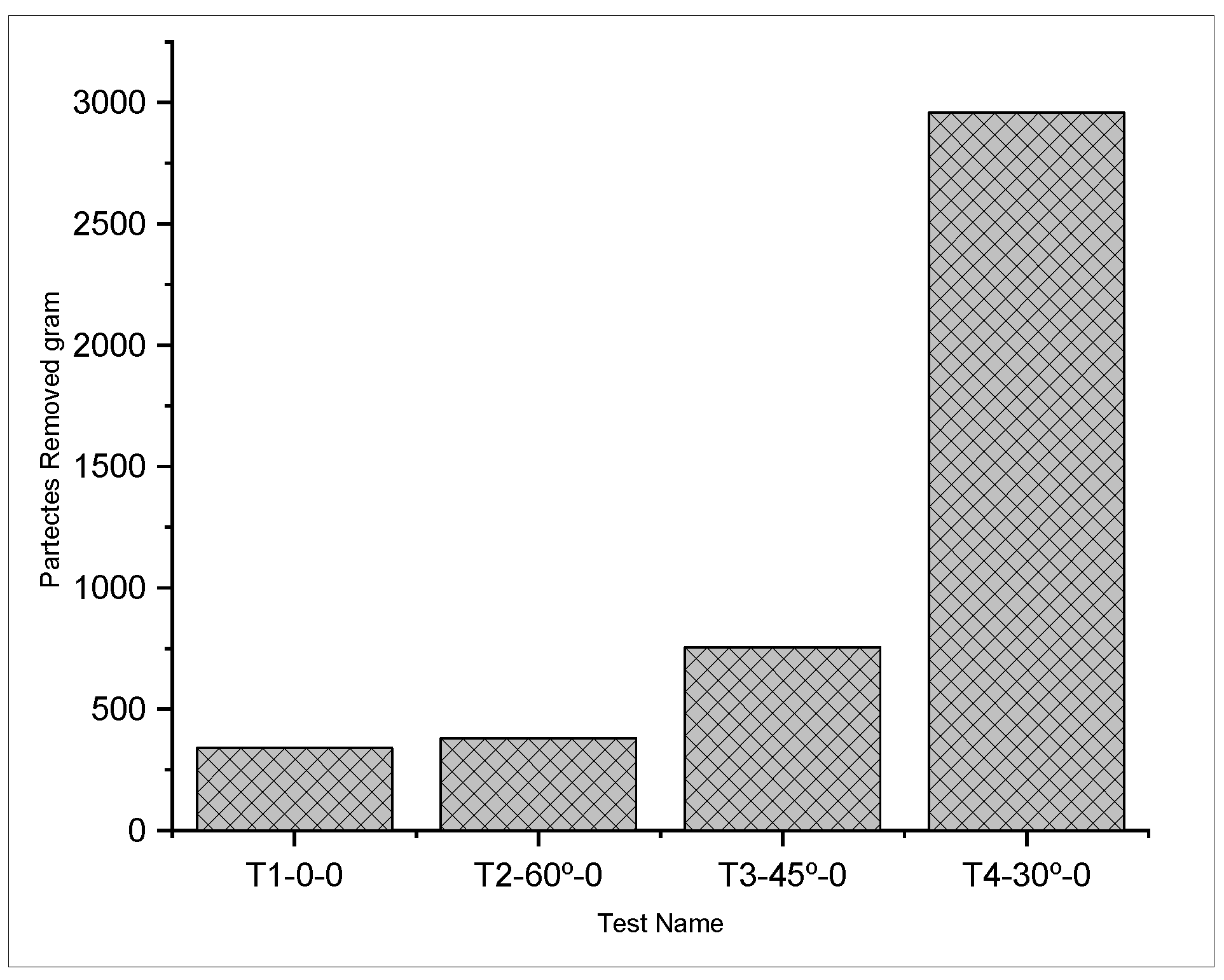
The weights of the sediments removed using the HSSR and FBHSSR systems are depicted in
Figure 9. As can be seen, with the FBHSSR method, the weight increased significantly by 800% when the fan blade angle was 30°, whereas the increase was 200% and 117% at 45° and 60° angles, respectively.
4.2. Influence of the Effective Head of the Suction Pipe on the Systems’ Performance
Figure 10 shows the influence of the relationship between effective head on the scour hole dimensional properties for the FBHSSR and HSSR systems. Three effective head values were used for the suction siphon. The results showed that the scour diameter (R/D) and scour depth (E/D) increased as the effective head (H/D) increased.
Additionally, the percentage of sediment removal (SR%) increased as the effective head increased. However, the systems’ efficiency remained constant as the volume of sucked water increased.
4.3. Effect of the Height of the Inlet from the Sand Layer on the Systems’ Performance
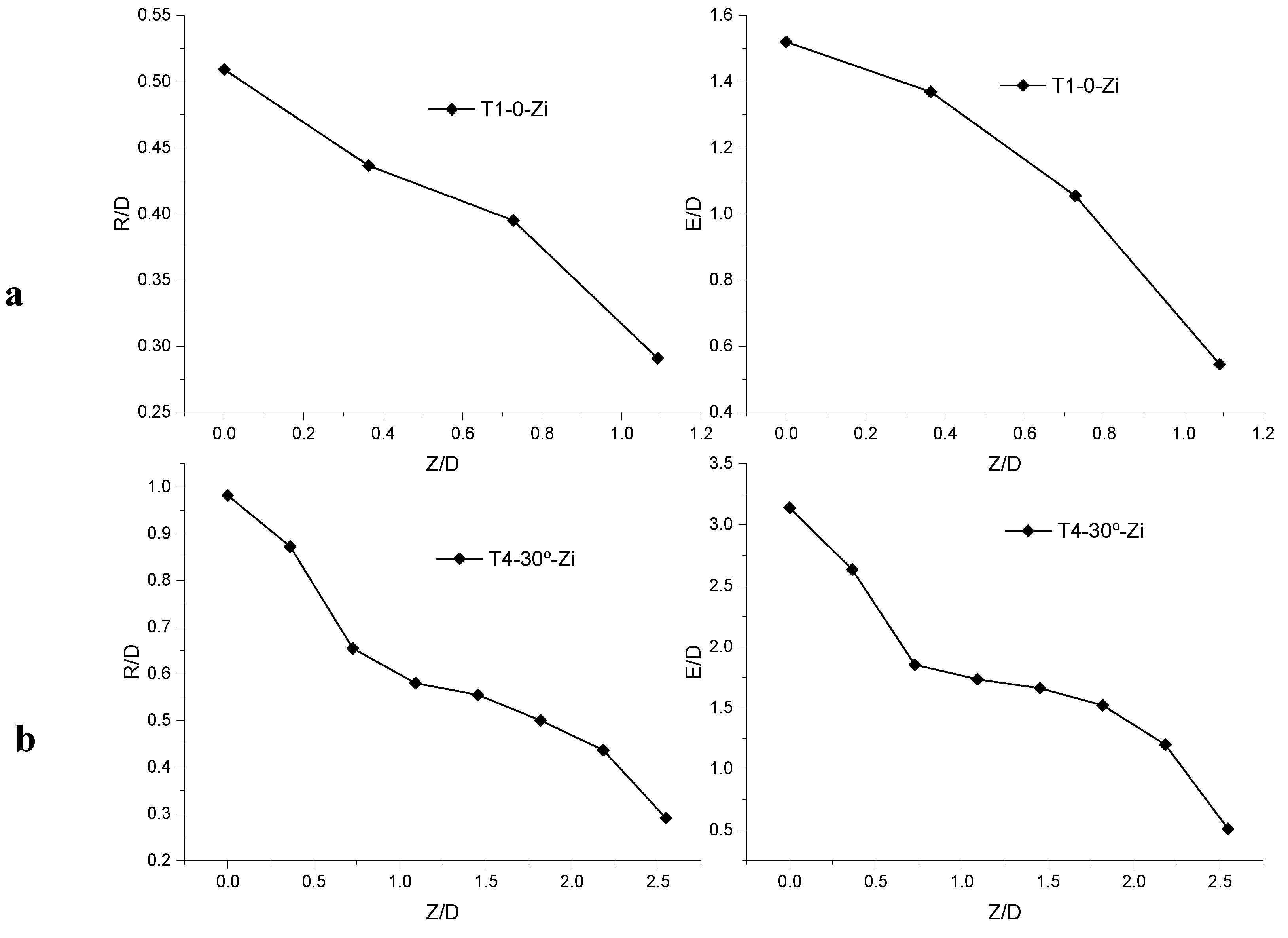
The observations illustrated that the inlet height (
Z) significantly affected the depth and diameter of the scour hole. As shown in
Figure 11a,b, the values of E/D and R/D decreased when the Z/D of the systems increased.
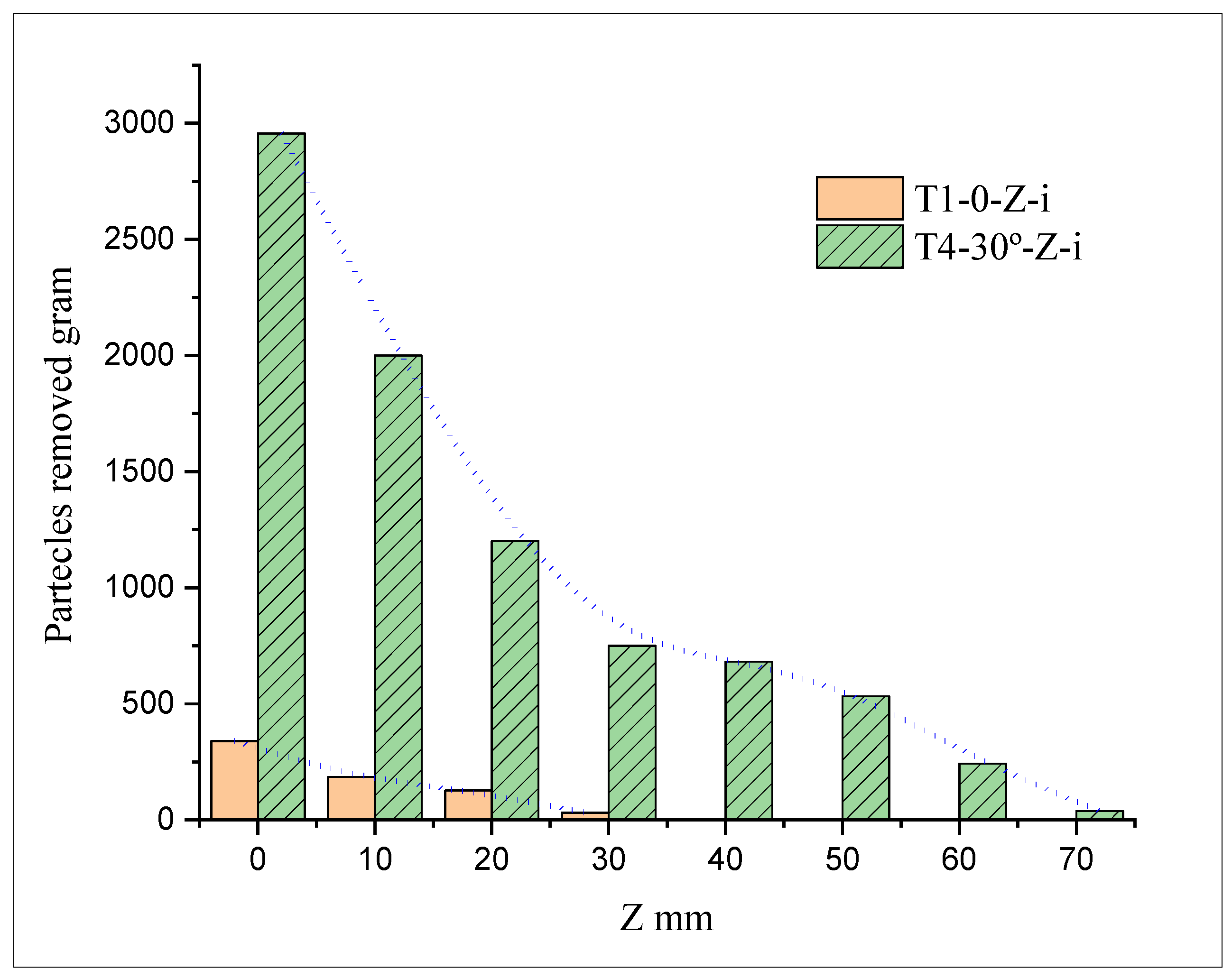
Figure 12 shows that the critical values of SR for the HSSR and FBHSSR systems were 30 cm and 70 cm, respectively.
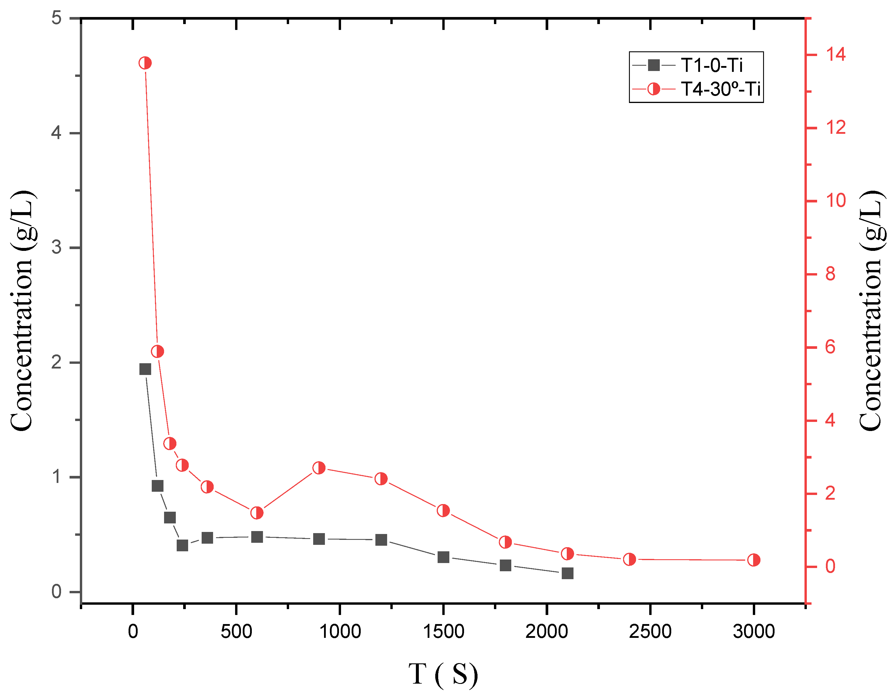
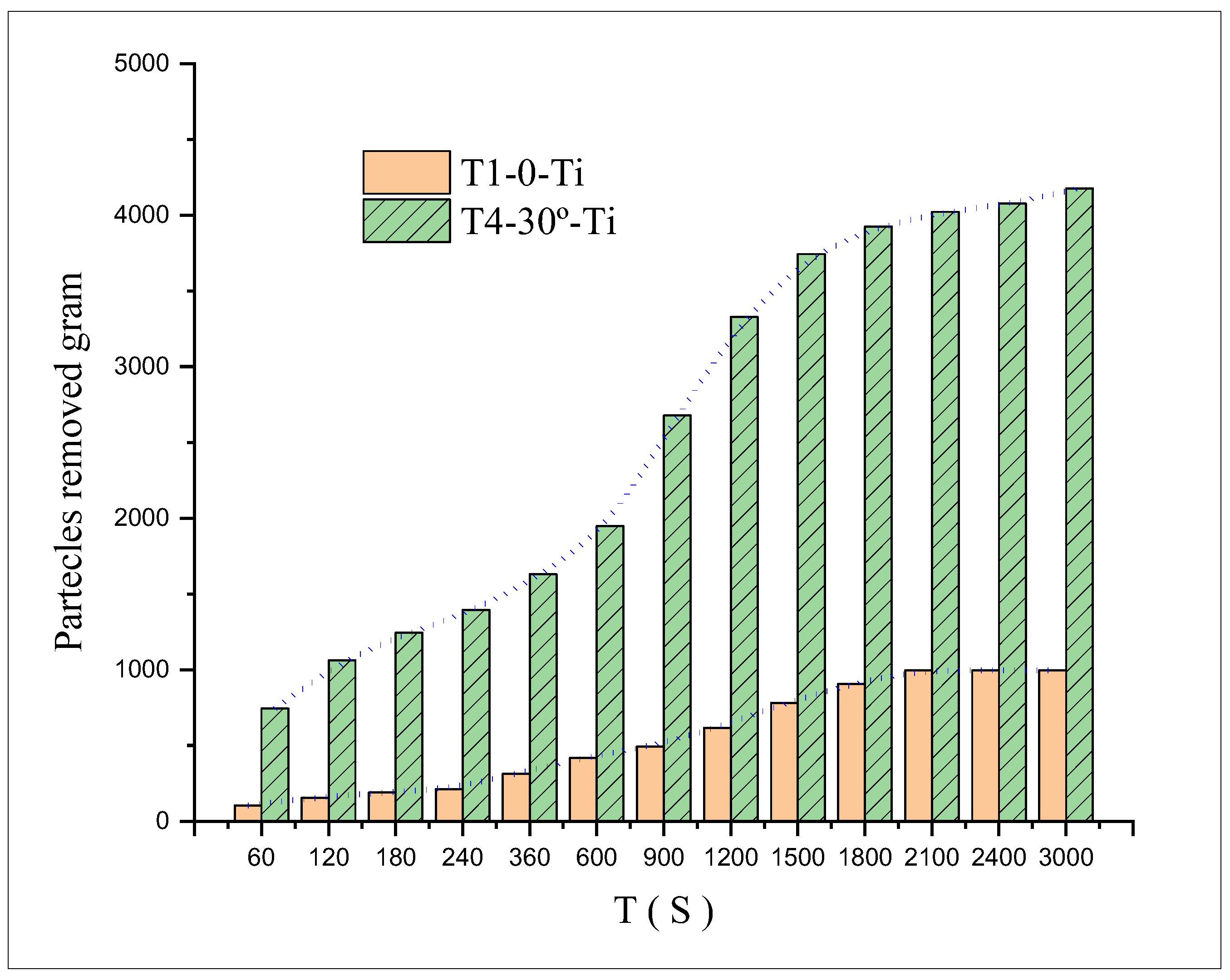
4.4. Time Effect on the Proportion of Concentration for Sediment Removal
A total of 67 samples were collected within the test period in this study. Then, the concentration was calculated accordingly to study the effect of concentration proportion in removing the sediments. The concentration graphs for the FBHSSR and HSSR systems are shown in
Figure 13. As can be seen, as the experiment period lengthened, the particle concentration decreased. However,
Figure 14 illustrated that the weight of removed sediments increased as the test period lengthened. Moreover, the systems’ efficiency diminished over time due to the low concentration.
Finally, the present study has shown that the performance of the HSSR system depends on the system’s efficiency to suspend particles in water. Therefore, a vortex can be used to obtain a higher velocity of water compared to the critical velocity of sediment particles in order to initiate the motion for sediment removal.
5. Conclusions
The present study developed a new design for improving hydrosuction performance using the FBHSSR system. Experimental tests with various conditions were conducted to compare the FBHSSR and HSSR systems. The difference in the water level between the reservoir and the suction tube outlet significantly affected the parameters of the FBHSSR system, which are the fan blade angles (α), the height of the inlet from the sediment surface layer (Z), and the effective water head (H) on the suction. The results indicated that the efficiency of the FBHSSR system with smaller fan blade angle values (α) was higher than with larger α. Based on the test results, the best system efficiency was determined at the fan blade angle of 30°. At this optimal angle, the weight of the removed sediments as well as the scour hole diameter and depth for the FBHSSR system were 9, 2, and 2 times greater, respectively, than those of the HSSR system.
The critical height of the entrance tube from the soil surface at the optimal angle was determined through the tests of the laboratory model. The critical SR values for the FBHSSR and HSSR systems were, respectively, 2.5 and 1 times higher than the diameter of the suction pipe. However, the efficiency of the systems decreased as the height of the inlet increased.
On the other hand, the efficiency of the systems and scour hole properties increased as the effective head (H) increased. The water head represented the difference in the elevation between the reservoir’s water surface and the siphon pipe’s exit.
Based on the volume of sucked water due to the weight of the removed sediments, the test duration was found to directly impact the efficiency of the FBHSSR system. In addition, increasing the testing time led to decreased efficiency and increased geometry of the scour hole. Future work is therefore recommended to further study the impact of vortex velocity for obtaining the best performance of the FBHSSR system for removing particles in water.
Author Contributions
Conceptualization, M.H.R.; methodology, writing—original draft preparation and formal analysis, N.M.N. and M.S.A.A.; writing—review and editing, M.H.Z. and M.K.A.W.; visualization, M.A.A.B.; resources, M.R.R.M.A.Z.; supervision and project administration. All authors have read and agreed to the published version of the manuscript.
Funding
This research received no external funding.
Data Availability Statement
The data presented in this study are available on request from the corresponding author.
Conflicts of Interest
The authors declare no conflict of interest.
Notation
The symbols used in this study are as follows:
| H | Effective head of water |
| Z | Height of inlet siphon from soil^’ surface |
| D | Diameter of suction pipe |
| D50 | median size of the particles |
| functions |
| T | test period |
| α | angle of fan blades |
| N | number of fan blades |
| pump^’ s flow rate |
| R | Hole diameter |
| E | Hole depth |
| μ | water dynamic viscosity |
| g | gravitational acceleration |
| Renols number |
| specific soil gravity |
| Froude number |
| water density |
| soil density |
| sediment removal |
References
- Moghbeli, A.; Khanjani, M.J.; Zounemat-Kermani, M. An experimental study of the geometric performance of the hydrosuction dredging system. Acta Geophys. 2021, 69, 271–283. [Google Scholar] [CrossRef]
- Vlastara, M.; Zarris, D.; Panagoulia, D. Sediment Yield Modelling in Transboundary River Basins: Application to the Nestos River Basin; Springer: Berlin/Heidelberg, Germany, 2000; pp. 1–8. [Google Scholar]
- Zarris, D.; Evdoxia, L.E.; Panagoulia, D.G.; Lykoudi, E.; Panagoulia, D. Sediment Yield Assessment in Greece Catchment Hydrology under GISS-Climate Changes View Project Transient Climate Models and Irrigation View Project Sediment Yield Assessment in Greece. 2012, pp. 261–268. Available online: https://www.researchgate.net/publication/268030258_Sediment_Yield_Assessment_in_Greece?channel=doi&linkId=545f5af60cf2c1a63bfda7ee&showFulltext=true (accessed on 12 January 2023). [CrossRef]
- Chen, S.-C.; Wang, S.-C.; Wu, C.-H. Sediment removal efficiency of siphon dredging with wedge-type suction head and float tank. Int. J. Sediment Res. 2010, 25, 149–160. [Google Scholar] [CrossRef]
- Ke, W.-T.; Chen, Y.-W.; Hsu, H.-C.; Toigo, K.; Weng, W.-C.; Capart, H. Influence of Sediment Consolidation on Hydrosuction Performance. J. Hydraul. Eng. 2016, 142, 04016037. [Google Scholar] [CrossRef]
- Naisen, J.; Rcsecuch, B.1.C.I.O.W.R.A.H.P.; Lingyan, F. Problems of reservoir sedimentation in China. J. Lake Sci. 1997, 9, 1–8. [Google Scholar] [CrossRef]
- Liu, J.; Minami, S.; Otsuki, H.; Liu, B.; Ashida, K. Environmental impacts of coordinated sediment flushing. J. Hydraul. Res. 2004, 42, 461–472. [Google Scholar] [CrossRef]
- Rizzuan, W.N.; Zainol, M.R.R.M.A.; Ab Wahab, M.; Kang, C.W.; Setiawan, I. A review: Removal of sediment in water reservoir by using Siphon. IOP Conf. Ser. Earth Environ. Sci. 2021, 646, 012040. [Google Scholar] [CrossRef]
- Kantoush, S.A.; Sumi, T.; Murasaki, M. Evaluation of sediment by pass efficiency by flow field and sediment concentration monitoring techniques. Ann. J. Hydraul. Eng. JSCE 2011, 55, 169–174. [Google Scholar] [CrossRef] [Green Version]
- Lee, C.; Foster, G. Assessing the potential of reservoir outflow management to reduce sedimentation using continuous turbidity monitoring and reservoir modelling. Hydrol. Process. 2012, 27, 1426–1439. [Google Scholar] [CrossRef]
- Hotchkiss, R.H.; Huang, X. Hydrosuction Sediment-Removal Systems (HSRS): Principles and Field Test. J. Hydraul. Eng. 1995, 121, 479–489. [Google Scholar] [CrossRef]
- Rehbinder, G. Enlevément des depots sédimentaires au moyen d’un siphon à flux critique. J. Hydraul. Res. 1994, 32, 845–860. [Google Scholar] [CrossRef]
- Ullah, S.M.; Mazurek, K.A.; Asce, M.; Rajaratnam, N.; Asce, F.; Reitsma, S. Siphon Removal of Cohesionless Ma-terials. J. Waterw. Port Coast. Ocean. Eng. 2005, 131, 115–122. [Google Scholar] [CrossRef] [Green Version]
- Shrestha, H.S. Application of Hydrosuction Sediment Removal System (HSRS) on Peaking Ponds. Hydro Nepal: J. Water Energy Environ. 2012, 11, 43–48. [Google Scholar] [CrossRef] [Green Version]
- Slotta, L.S. Flow visualization techniques used in dredge cutterhead evaluation. In World Dredging Conference; World Organization of Dredging Associations: Amsterdam, The Netherlands, 1968; pp. 56–77. [Google Scholar]
- Brahme, S.B.; Herbich, J.B. Hydraulic Model Studies for Suction Cutterheads. J. Waterw. Port Coastal Ocean Eng. 1986, 112, 591–606. [Google Scholar] [CrossRef]
- Mahdavi-Meymand, A.; Zounemat-Kermani, M.; Qaderi, K. Vortex Hydrosuction: A New Sediment Removal System. J. Hydraul. Eng. 2021, 147, 04021048. [Google Scholar] [CrossRef]
- Asiaban, P.; Kouchakzadeh, S. Enhanced hydrosuction performance for cohesive sediment removal in low-head reservoirs. Ain Shams Eng. J. 2017, 8, 491–497. [Google Scholar] [CrossRef] [Green Version]
- Issa, I.E.; Al-Ansari, N.; Khaleel, M.; Knutsson, S. Experimental Analysis of Sediment Deposition Due to Backwater Effect up-stream a Reservoir Experimental Analysis of Sediment Deposition Due to Backwater Effect up-stream a Reservoir’. J. Civil Eng. Archit. 2014, 9, 1193–1201. Available online: https://www.researchgate.net/publication/266026334 (accessed on 12 January 2023).
- Rohani, I.; Paroka, D.; Thaha, M.A.; Hatta, M.P. Dimensional Analysis of Compound Section in The Regulate Section Channel Model for Maintenance Main Channel. IOP Conf. Ser. Earth Environ. Sci. 2021, 921. [Google Scholar] [CrossRef]
- Garcia, M.H. Sedimentation Engineering; ASCE: Reston, VI, USA, 2007. [Google Scholar] [CrossRef]
| Disclaimer/Publisher’s Note: The statements, opinions and data contained in all publications are solely those of the individual author(s) and contributor(s) and not of MDPI and/or the editor(s). MDPI and/or the editor(s) disclaim responsibility for any injury to people or property resulting from any ideas, methods, instructions or products referred to in the content. |
© 2023 by the authors. Licensee MDPI, Basel, Switzerland. This article is an open access article distributed under the terms and conditions of the Creative Commons Attribution (CC BY) license (https://creativecommons.org/licenses/by/4.0/).


 ,
, 


