
Nitrogen-Doped Core-Shell Mesoporous Carbonaceous Nanospheres for Effective Removal of Fluorine in Capacitive Deionization

1
Resources and Environment Innovation Institute, Shandong Jianzhu University, Jinan 250101, China
2
College of Environmental Science and Engineering, Nankai University, Tianjin 300071, China
3
The Second Construction Limited Company of China Construction Eighth Engineering Division, Jinan 250011, China
4
Huzhou Nanxun District Jianda Ecological Environment Innovation Center, Shandong Jianzhu University, Jinan 250101, China
*
Authors to whom correspondence should be addressed.
Water 2023, 15(3), 608; https://doi.org/10.3390/w15030608
Submission received: 10 January 2023
/
Revised: 23 January 2023
/
Accepted: 30 January 2023
/
Published: 3 February 2023
(This article belongs to the Special Issue Adsorption Technology for Water and Wastewater Treatments)
Abstract
:Fluorine pollution of wastewater is a global environmental problem. Capacitive deionization has unique advantages in the defluorination of fluorine-containing wastewater; however, the low electrosorption capacity significantly restricts its further development. To overcome this limitation, nitrogen-doped core-shell mesoporous carbonaceous nanospheres (NMCS) were developed in this study based on structural optimization and polarity enhancement engineering. The maximal electrosorption capacity of NMCS for fluorine reached 13.34 mg g−1, which was 24% higher than that of the undoped counterpart. NMCS also indicated excellent repeatability evidenced by little decrease of electrosorption capacity after 10 adsorption-regeneration cycles. According to material and electrochemical measurements, the doping of nitrogen into NMCS resulted in the improvement of physicochemical properties such as conductivity and wettability, the amelioration of pore structure and the transformation of morphology from yolk-shell to core-shell structure. It not only facilitated ion transportation but also improved the available adsorption sites, and thus led to enhancement of the defluorination performance of NMCS. The above results demonstrated that NMCS would be an excellent electrode material for high-capacity defluorination in CDI systems.
1. Introduction
Fluorine (F−) is an indispensable trace element for the human body to maintain normal physiological activities. However, excessive intake of fluorine can be harmful to teeth, bones, central nervous system and reproductive system [1]. In recent years, with the rapid development of industries, increasing amounts of fluorine-containing wastewater have been produced in industrial processes such as metal smelting, steel and cement production, aluminum electrolysis, ceramics, pharmaceuticals and semiconductor manufacture [2]. The fluorine content of fluorine-containing wastewater is generally more than 100 mg L−1, and even reaches several thousand mg L−1 in some specific industries [3]. Due to the high migration ability of fluorine pollution, the direct discharge of fluorine-containing wastewater into the environment/water bodies will easily result in pollution of groundwater and drinking water sources, leading to fluorosis in drinkers. Therefore, the fluorine-containing wastewater must be defluoridated before it is permitted to be discharged into the environment/water bodies.
At present, the methods of adsorption, precipitation, reverse osmosis and ion exchange are commonly used for the purification of fluorine [4,5,6,7]. These methods have disadvantages such as high cost and secondary pollution. In recent years, capacitive deionization (CDI) has emerged as a promising electrochemical defluorination technology. The principle of CDI fluorine removal is based on double-electric-layer adsorption [8,9]. In CDI, as the fluid flows through the electrodes under the action of electric field, ions in the fluid can migrate to and be absorbed to the oppositely charged electrode to form a double-electric-layer. After adsorption saturation, the electrodes can be regenerated by being short-circuited, since the ions adsorbed to the electrodes can be re-released into the fluid in this state. Certain distinct advantages, such as simple operation, low cost, low energy consumption and environmentally friendly effects, make CDI competitive as an alternative defluorination technology [10,11]. CDI originated in the mid-1960s, and for many years the research on CDI has been mainly focused on desalination of seawater and brackish water, with little attention being paid to the defluorination applications of CDI. Tang et al. studied the defluorination performance of CDI using activated carbon in batch mode and verified the feasibility of CDI for defluorination application in brackish groundwaters [12]. Epshtein et al. fabricated flow electrodes using SiO2 and constructed flow-electrode CDI. They successfully removed fluorine from acidic wastewater [13]. In the study by Gaikwad et al., defluorination and removal of chromium were simultaneously achieved using activated carbon in CDI [14]. Nevertheless, research on the removal of fluorine using CDI is still in its infancy, evidenced by the limited amount of available literature. The relatively low electrosorption performance of CDI cannot meet the standards for commercial application. For example, Park et al. reported that the defluorination capacity of the reduced graphene oxide/hydroxyapatite composite was only 0.19 mg g−1 at 1.2 V [15]. Tang et al. observed the defluorination capacity of activated carbon ranging from 0.4 to 0.8 mg g−1 at 1.2 V at flow rates ranging from 30 to 100 mL min−1 [16]. Gaikwad et al. prepared activated carbon derived from tea waste biomass, which showed a defluorination capacity of 0.74 mg g−1 with an initial fluorine of 10 mg L−1 and a defluorination capacity of 2.49 mg g−1 with an initial fluorine of 10 mg L−1, respectively [17]. Thus, more research is needed for the further improvement of electrosorption performances.
As the core component of CDI, the electrode plays a crucial role in affecting the defluorination performance of CDI. Porous carbons are generally used to fabricate the CDI electrode due to their low fabrication cost, favorable porous structure, excellent electrical conductivity and remarkable electrochemical stability [18,19,20]. Among porous carbons, the mesoporous carbons have been considered to be superior candidates because of their larger aperture, which can facilitate ion transport and, hence, enhance the availability of surface area [21,22]. Therefore, the mesoporous carbons are generally considered to possess more accessible active adsorption sites for fluorine as compared with the microporous carbons. However, the pure carbonaceous materials reported in the literature exhibited low defluorination performance [15,16]. Recently, researchers have attempted to modify pure carbonaceous carbons in order to improve the defluorination performance. The modification methods have mainly focused on metal/metal oxide/metal hydroxide doping, such as Ti(OH)4 [23], La(III) [24,25], TiO2 [26], and so on. However, as yet there has been no breakthrough improvement in the defluorination performance. It has been reported that pure carbonaceous materials generally display inferior wettability and electrical conductivity, which could significantly hinder the adsorption of ions in the carbon framework [27,28]. Heteroatomic doping, such as nitrogen doping, has been proven to be an effective way to enhance the wettability and electrical conductivity of carbonaceous material in CDI desalination applications [29,30]. However, little attention has been paid to the modification of porous carbons by heteroatomic doping to improve the defluorination performance of CDI. The amelioration of wettability is mainly associated with the introduction of nitrogenous polar functional groups into the carbon framework, which displays benign affinity to aqueous solvents through nitrogen doping. The improvement of electrical conductivity through nitrogen doping is mainly due to the electron-rich peculiarity of nitrogen, which can bring more electrons to the delocalized π-system of the carbon framework. Based on the above facts, nitrogen-doped mesoporous carbons are extremely attractive.
In this study, the nitrogen-doped mesoporous carbonaceous nanospheres (NMCS) with core-shell structure were prepared via a gradient sol-gel method for efficient defluorination in CDI systems. As a comparison, mesoporous pure carbonaceous nanospheres without heteroatom doping (MCS) were also prepared. The defluorination performance was studied in a series of batch mode-recirculating mode experiments, and the important contribution of nitrogen doping to the defluorination performance of carbon materials was analyzed in depth using multiple material characterizations and electrochemical analyses.
2. Materials and Methods
2.1. Materials Synthesis and Electrode Fabrication
The precursors of MCS and NMCS were prepared via a gradient sol-gel method [31]. In a typical procedure, 1.5 g of resorcinol (Guangfu Fine Chemical Research Institute, Tianjin, China) and 1.5 g of cetyltrimethylammonium bromide (CTAB, Guangfu Fine Chemical Research Institute, Tianjin, China) were dissolved in a mixed solvent of ammonia solution (25 wt.%, Fengchuan, Tianjin, China) and ethanol (Riolon, Tianjin, China) with a volume ratio of 5:3. After magnetically stirring for 30 min at room temperature, the mixture was added with 7.5 mL of tetraethyl orthosilicate (TEOS, Jiangtian, Tianjin, China) and 2.1 mL of formaldehyde (37 wt.%, Ailan, Shanghai, China). The mixture continued to be magnetically stirred for 24 h at room temperature and was then transferred to Teflon-lined autoclaves to carry hydrothermal reaction for 24 h at 100 °C. To prepare NMCS, the above precursors were ground with urea (Jiangtian, Tianjin, China) for 2 h using a ball mill for intensive mixing. Subsequently, the resulting products were carbonized at 700 °C 180 min in a nitrogen atmosphere. As a comparison, MCS was prepared by directly carbonizing the hydrothermal precursors without adding urea. Next, the carbonizing products were soaked in 10 wt.% hydrofluoric acid (HF, 40 wt.%, Fengchuan, Tianjin, China) for 24 h to remove impurities. Finally, the obtained products were washed with deionized water and ethanol and dried in vacuum overnight.
The as-acquired MCS and NMCS powders were mixed with carbon black and PTFE with a mass ratio of 8:1:1. The mixture was dispersed in ethanol solution and ultrasonically stirred to form a homogenized slurry. The electrode was fabricated by pressing the slurry onto a titanium mesh current collector using a noodle machine. Finally, the electrodes were dried in vacuum in order to remove the residual ethanol.
2.2. Materials Characterization
The morphology of as-acquired MCS and NMCS were characterized by scanning electron microscope (SEM, Hitachi S-3500N, Hitachi, Tokyo, Japan) equipped with an energy-dispersive X-ray spectrometer (EDS) and high-resolution transmission electron microscope (TEM, JEM-ARM200F, JEOL, Tokyo, Japan). The structure of MCS and NMCS was analyzed by X-ray diffraction (XRD, D/max-2500, Rigaku, Tokyo, Japan). The porous structure of MCS and NMCS was analyzed by the Brunauer–Emmett–Teller (BET) method using a density functional theory (DFT) model. The defect structure and graphitization degree of MCS and NMCS were analyzed by Raman spectroscopy (SR-500I-A, Time Tagger, Wuhan, China). The elements and compositions of MCS and NMCS were analyzed by X-ray photoelectron spectroscopy (XPS, ESCALAB 250 XI, Thermo Scientific Escalab, Waltham, MA, USA). The wettability of MCS and NMCS was measured by the drop shape analysis system (Kruss DSA 100S, KRUSS, Shanghai, China).
2.3. Electrochemical Measurements
The electrochemical measurements in this study included cyclic voltammetry (CV), galvanostatic charging–discharging (GCD) and electrochemical impedance spectroscopy (EIS). All measurements were performed in 1 mol L−1 NaF solution using a potentiostat (chi760e, CH Instruments, Shanghai, China). A three-electrode system was employed with a carbonaceous electrode as the working electrode, a platinum gauze electrode as the counter electrode and a saturated calomel electrode as the reference electrode.
The measurements of EIS were with a frequency range of 0.1 to 100,000 Hz. For CV measurements, the potential window was ±0.5 V, and the scan rate varied from 10 to 100 mV·s−1. Based on the CV curves, the specific capacitance can be ascertained according to the following equation:
where C is the specific capacitance (F g−1), S is the area of the CV curve, ΔV is the voltage window (V), v is the scan rate (V s−1) and m is the mass of active material on the working electrode (g).
In GCD measurements, a series of current densities including 0.2, 0.5 and 1 A g−1 were employed with a potential window of ±0.5 V. Based on the GCD curves, the charge/discharge capacitance can be determined according to the following equation:
where I/m is the current density (A g−1), Δt is the charge/discharge time (s) and ΔV is the voltage window (V).
2.4. Defluorination Experiment
The defluorination experiment was conducted in a self-made CDI cell in a batch mode-recirculating mode. As shown in Figure S1, the CDI cell was composed of a rectangular plastic chamber with a pair of parallel electrodes attached to plastic plates inside. Each electrode had an area of around 7 cm2 and a thickness of around 30 μm. In the defluorination experiment, the adsorption period and the electrode regeneration period alternated. The adsorption period proceeded with 100 mL of NaF solution circulating in the CDI cell through a peristaltic pump with a voltage being applied between the two electrodes. The circulating rate of the circulating solution was constant at 10 mL·min−1, while the fluorine concentration of the circulating solution varied from 250 to 1000 mg L−1. The conductivity of the circulating solution was continuously monitored through a conductivity meter (INESA, DDS-11A, INESA, Shanghai, China), and the concentration of the circulating solution was ascertained based on the calibration curve between the conductivity and concentration, as shown in Figure S2. The electrode regeneration period started when the conductivity of the circulating solution remained unchanged, which indicated the adsorption equilibrium of fluorine onto the electrodes. In this period, the voltage between the two electrodes was removed and the electrodes were in a short circuit.
The electrosorption capacity at a typical time can be calculated according to the following equation:
where C0 is the initial fluorine concentration of the circulating solution (mg L−1), Ct is the fluorine concentration of the circulating solution at adsorption time of t (mg L−1), V is the volume of the circulating solution (L) and m is the mass of active material (g).
The electrosorption rate at a typical time can be calculated according to the following equation:
where Γt is the electrosorption capacity at adsorption time of t (mg g−1) and t is the adsorption time (min).
3. Results and Discussion
3.1. Material Characterizations
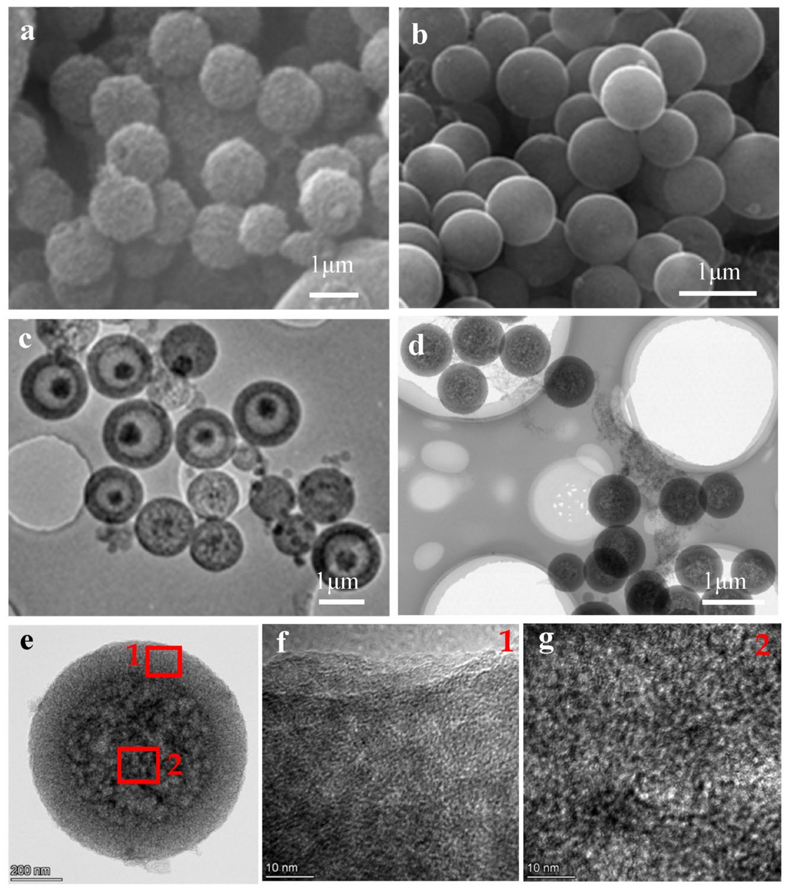
Figure 1 shows the morphological features of MCS and NMCS. As depicted in the SEM image, MCS exhibited a regular spherical morphology with rough surfaces and with a diameter ranging from 900 to 1400 nm, as shown in Figure 1a. According to Figure 1b, NMCS retained the regular spherical morphology after nitrogen doping while displaying much smoother surfaces and smaller size dimensions. The TEM image shown in Figure 1c indicates the unique yolk-shell structure of MCS. Interestingly, as shown in Figure 1d, the doping of nitrogen resulted in the structural transformation of NMCS from yolk-shell to core-shell spheres. The thickness of the shells of both NMCS and MCS were in the range of 100–150 nm. High-resolution TEM images were further employed to depict the microstructure of the core and shell of NMCS. It is evident from Figure 1e–g that the core had a much looser structure, while more homogeneous and smaller-sized pores were distributed in the core. EDS mapping images of NMCS, as shown in Figure S3, demonstrated that nitrogen was introduced into both the core and shell of NMCS and was evenly distributed across the core and shell.
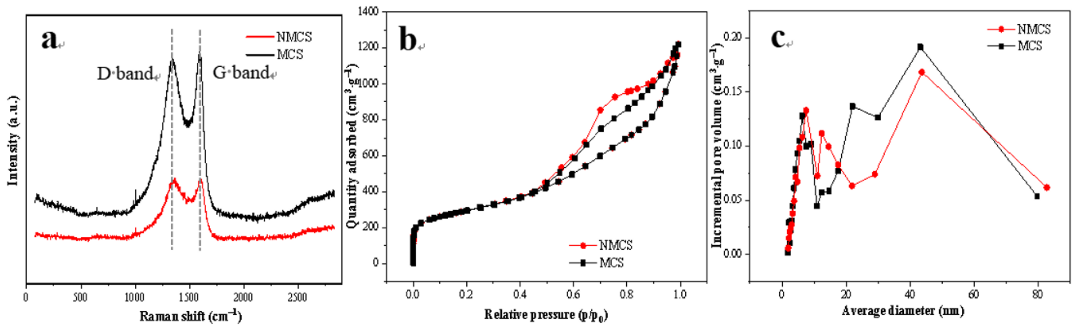
Figure 2 shows the structural features of MCS and NMCS. Raman spectroscopy was employed to analyze the features of NMCS and MCS. In Figure 2a, two prominent peaks appeared at around 1350 cm−1 (D band) and at 1595 cm−1 (G band). The D band was reported to result from the Csp3 hybridization and could be assigned to defects and disordered structures [32]. The G band was reported to be derived from the Csp2 hybridization and could correspond to the crystalline graphitic structure [33]. The relative intensity ratio of the D band and the G band (ID/IG) is extensively used as an indicator to reflect the disorder degree of carbonaceous materials. The high ID/IG values of NMCS (0.999) and MCS (0.982) demonstrated their disorder features in which abundant defects were distributed. Nevertheless, NMCS displayed a higher ID/IG value as compared with MCS, indicating that more structural disorders and surface defects were formed in the framework of NMCS caused by the doping of nitrogen [34]. The generation of surface defects in carbonaceous materials can promote ion diffusion, provide more accessible site for ion adsorption and, thus, is beneficial for ion removal.
The pore structures of MCS and NMCS were analyzed based on N2 adsorption/desorption isotherms. As shown in Figure 2b, both isotherms of NMCS and MCS show obvious hysteresis loops, which can be assigned to type-IV adsorption/desorption isotherm pattern. The type-IV adsorption/desorption isotherm pattern has been reported to be a typical characteristic of the mesoporous structure [35]. The pore size distribution curves of MCS and NMCS are shown in Figure 2c. The porous structure of MCS and MMCS is mainly composed of mesopores, as evidenced by the fact that the pore size is mainly distributed in the range of 2~50 nm. The average pore diameter of MCS and NMCS was 43.2 and 43.7 nm, respectively. As listed in Table 1, the specific surface area of MCS derived from mesopores was 771 m2 g−1, which was around 72.9% of the total specific surface area (1058 m2 g−1). After nitrogen doping, the total specific surface area of NMCS (1049 m2 g−1) was almost unchanged. However, the specific surface area derived from mesopores increased to 819 m2 g−1, which was 78.1% of the total specific surface area. Similar to specific surface area results, according to Table 1 the pore volume of both MCS and NMCS is primarily derived from mesopores. The above results further illustrate the domination of mesoporous structure in the MCS and NMCS frameworks. The mesopores would promote ion diffusion in the carbon frameworks and provide more accessible sites for ion adsorption, since their large apertures can reduce the resistance for ion transfer to the interior structure [36]. Therefore, the higher specific surface area derived from mesopores endowed NMCS with more available adsorption sites as compared with MCS in spite of similar total adsorption sites, which would contribute to the improvement of CDI performance.
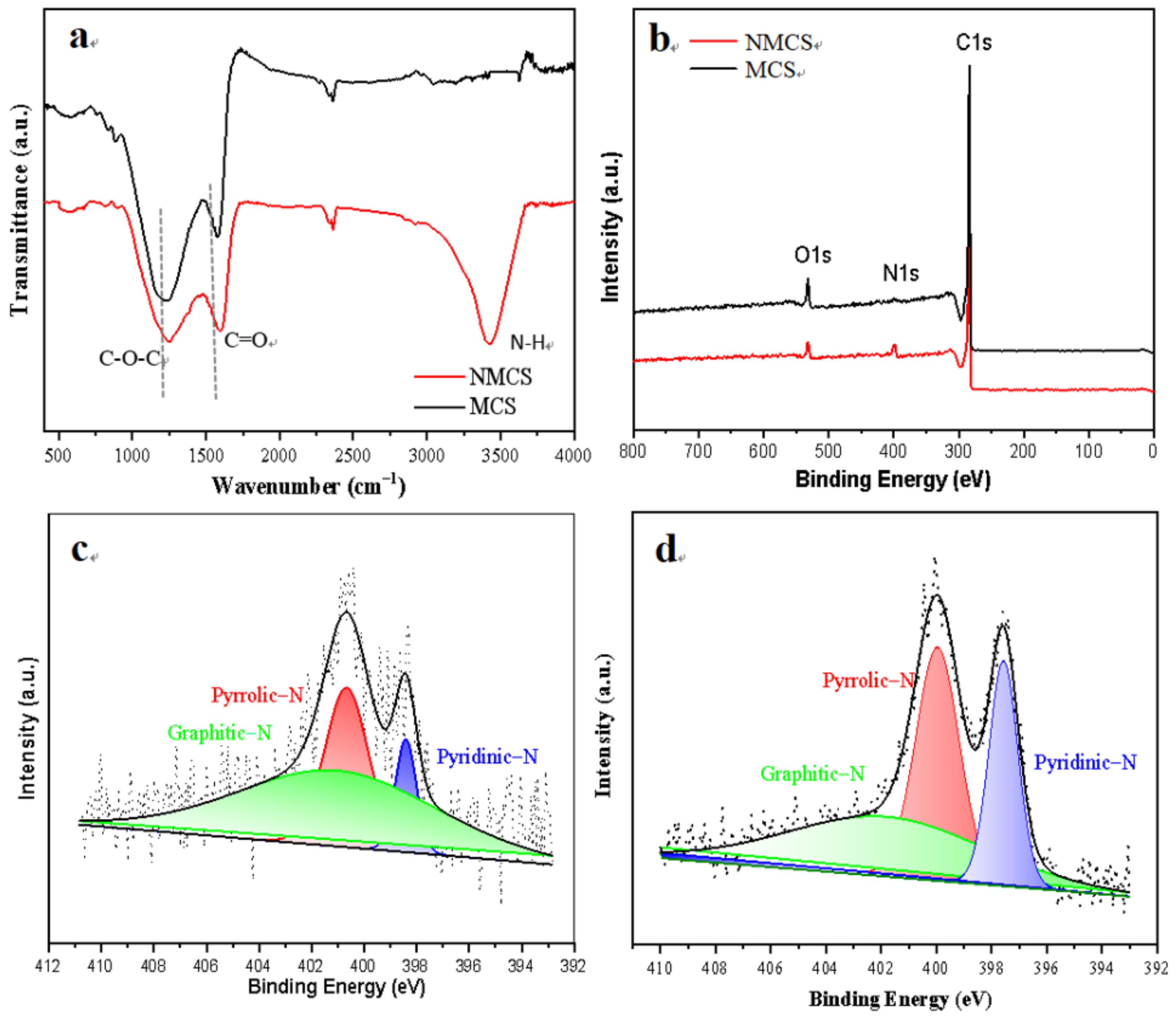
Figure 3 shows the compositions of MCS and NMCS. The FTIR spectrum of MCS shown in Figure 3a indicates two distinct absorption bands at around 1590 and 1250 cm−1, which can be ascribed to the stretching vibration of C=O and C-O-C, respectively [37]. In the spectrum of NMCS, an additional absorption band at around 3430 cm−1, corresponding to the stretching vibration of N-H, is observed according to Figure 3a, confirming the successful doping of nitrogen into NMCS [38]. The introduction of nitrogen-containing functional groups would significantly change the wettability of carbonaceous material. As shown in Figure S4, the contact angle of NMCS decreased from 35.77° to 17.86° after nitrogen doping, which is associated with the benign affinity of nitrogen-containing functional groups to aqueous solution. The amelioration of wettability of NMCS would enhance the utilization of the specific surface area, thus, more sites can be available for ion adsorption [39]. The content of nitrogen doped was quantitatively analyzed by XPS measurement. As shown in Figure 3b, the survey spectrum of NMCS indicts a distinct N1s peak, but it almost disappears in the survey spectrum of MCS. According to Table 2, the nitrogen content of NMCS was 4.03%, which was significantly higher than that of MCS (0.31%). The above results further suggest the successful doping of nitrogen from urea. As shown in Figure 3c,d, the high-resolution N1s spectra of NMCS and MCS can be fitted into three peaks at around 398, 400 and 401 eV, corresponding to three configurations of nitrogen, i.e., pyridinic-N, pyrrolic-N and graphitic-N. It has been widely reported in the literature that pyridinic-N and pyrrolic-N are beneficial to boost capacitance through generating pseudocapacitance based on faradic reactions, and that graphitic-N contributes to improve the conductivity of carbonaceous materials [40,41]. According to Table 2, all the contents of pyridinic-N, pyrrolic-N and graphitic-N in NMCS were significantly increased as compared with MCS. Therefore, the electricity conductivity and capacitance behavior of NMCS would be enhanced significantly, as verified by the electrochemical measurements discussed in Section 3.2.
Based on the results outlined and discussed above, both MCS and NMCS have superior mesoporous structures which can provide abundant available sites for ion adsorption. The doping of nitrogen into NMCS resulted in morphologic transformation, structural amelioration and improved physicochemical properties such as conductivity and wettability. It not only facilitated ion transportation, but also improved the available sites for ion adsorption and, thus, would boost the defluorination performances in CDI systems.
3.2. Electrochemical Analysis
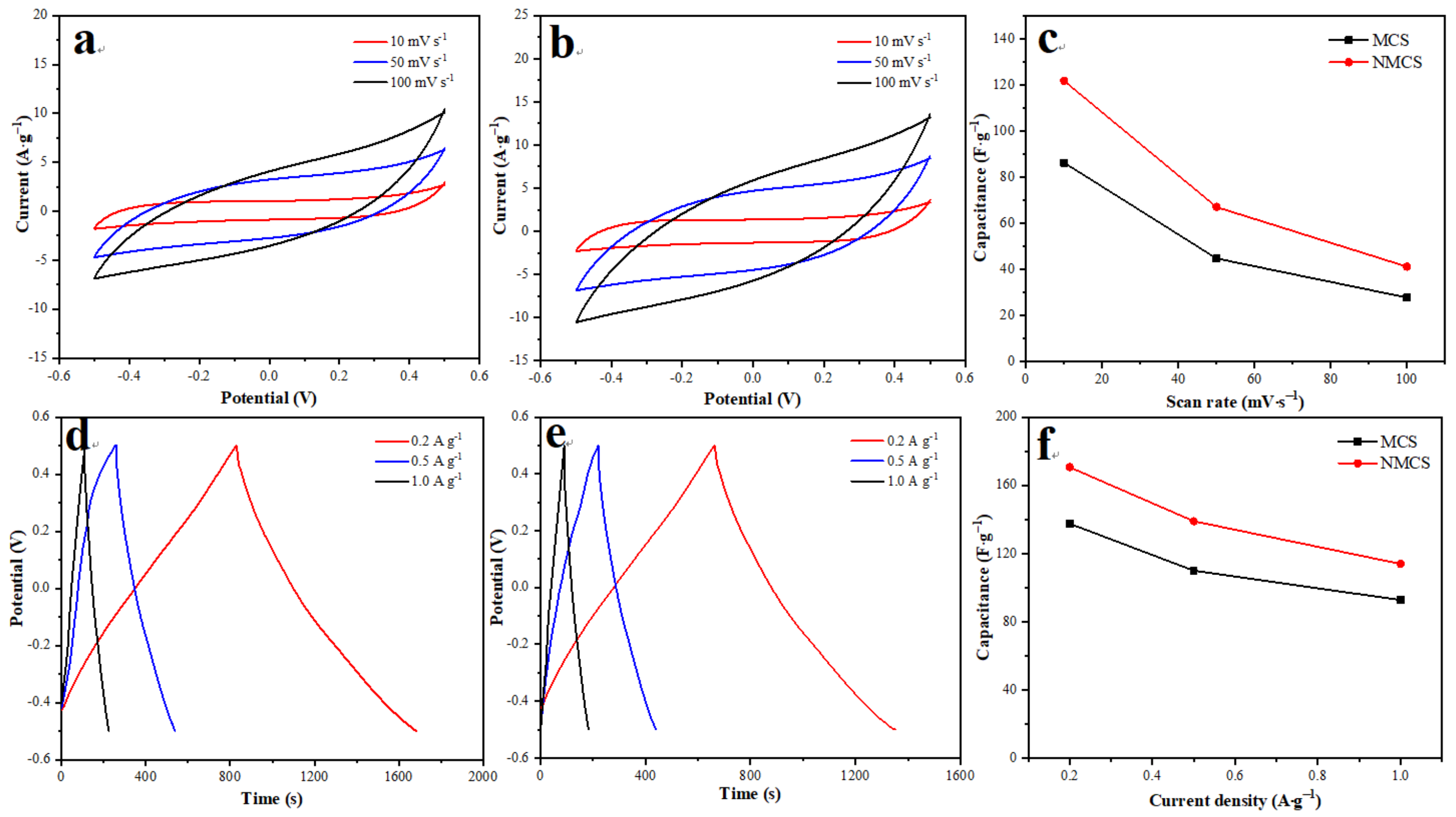
Figure 4 shows the electrochemical performances of MCS and NMCS. As shown in Figure 4a,b, the CV curves of both MCS and NMCS were close to rectangle at low scan rates, while they gradually changed into a fusiform shape with the increasing scanning rate due to the polarization effect of the electrodes [28]. The absence of redox peaks and excellent symmetry of CV curves demonstrates the ideal electrical-double-layer capacitance behaviors of MCS and NMCS [42]. According to Equation (1), the specific capacitance of MCS and NMCS at different scan rates was calculated, and the results are shown in Figure 4c. Apparently, the specific capacitance of both MCS and NMCS decreased with the increase of scan rate, which is attributed to the improved utilization of interior pores at lower scan rates. Nevertheless, NMCS displayed substantially higher specific capacitance as compared with MCS at all scan rates employed. The capacitance behaviors of MCS and NMCS were further analyzed by GCD curves. As shown in Figure 4d,e, both MCS and NMCS exhibited linear curves, implying the dominant contribution of electrical-double-layer adsorption to capacitance behaviors [43]. The high symmetry of GCD curves indicates the excellent repeatability of MCS and NMCS. The charge/discharge capacitance of MCS and NMCS under different current densities was calculated according to Equation (2), and the results are shown in Figure 4f. Evidently, the charge/discharge capacitance of NMCS was higher than that of MCS under all current densities measured, in accordance with the CV results. The superior capacitance behavior of NMCS is possibly associated with the facilitation of ion transportation and the improvement of available adsorption sites resulting from the doping of nitrogen.
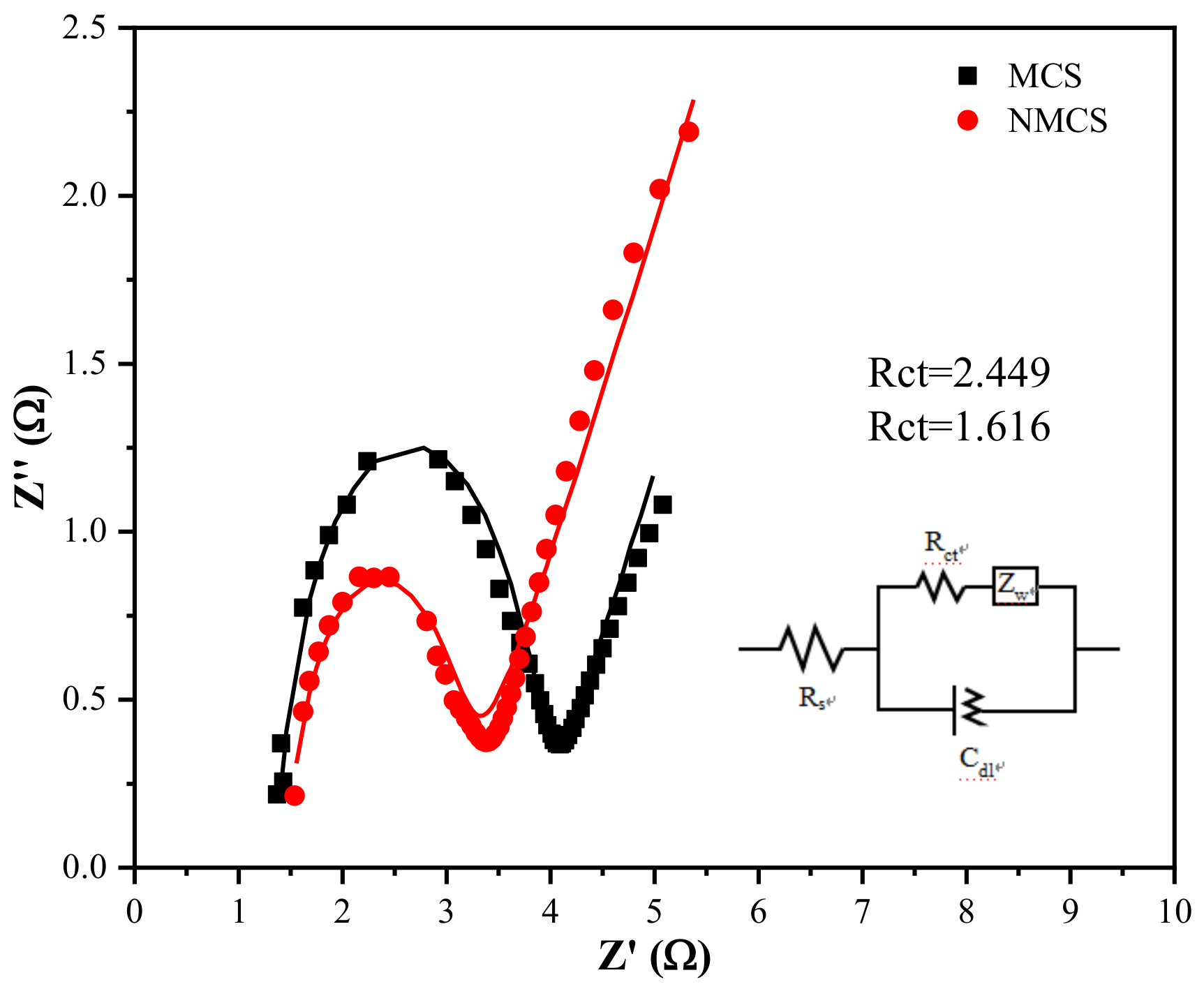
Figure 5 shows the EIS curves of MCS and NMCS with a frequency range of 0.1–100,000 Hz. The semicircle of MCS and NMCS in the high-frequency region is associated with the charge-transfer process within the microstructure. The inclined line of MCS and NMCS in the low-frequency region is related to the ion-diffusion process inside the framework. The charge-transfer resistance (Rct) of MCS and NMCS was fitted to be 2.449 and 1.616 Ω, respectively, based on the equivalent circuit model shown in Figure 5. The low Rct of NMCS implies that the doping of nitrogen reduces the barrier for ion to diffusion and improves the electrical conductivity to facilitate ion transport [44]. Based on the above results, NMCS exhibited superior capacitance and resistance behaviors as compared with their undoped counterparts, which is favorable for effective defluorination in CDI experiments.
3.3. CDI Performance Analysis
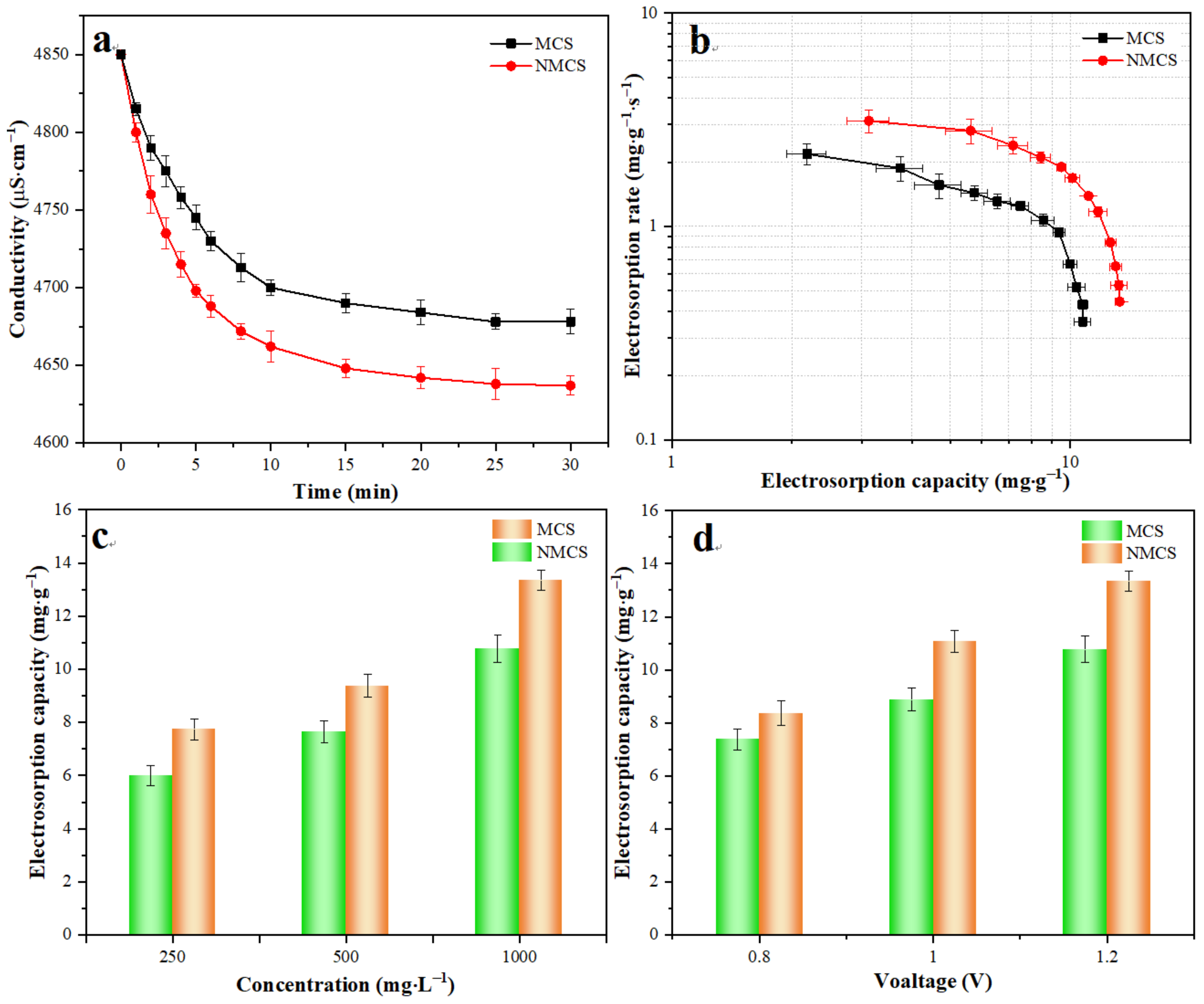
The defluorination performances of MCS and NMCS were studied with the initial fluorine concentration of 1000 mg L−1 at an applied voltage of 1.2 V. Figure 6a shows the change of conductivity with the electrosorption time in a typical cycle. The conductivity of MCS and NMCS initially decreased sharply and gradually reached a plateau with the increase of electrosorption time. In this study, MCS and NMCS reached adsorption saturation at around 30 min, as evidenced by the almost unchanged conductivity at this time. Nevertheless, NMCS indicated rapider and greater decline in conductivity than that of MCS, implying the boosted defluorination performance of NMCS after doping of nitrogen. Figure 6b shows the Kim plots of MCS and NMCS with the initial fluorine concentration of 1000 mg L−1 at an applied voltage of 1.2 V. The plot of NMCS is located on the upper right as compared with MCS, suggesting the superior electrosorption capacity and electrosorption rate of NMCS in CDI defluorination application. According to Figure 6b, NMCS exhibited an electrosorption capacity at saturation of 10.77 mg g−1 and maximal electrosorption rate of 2.20 mg g−1 s−1. The electrosorption capacity of NMCS at saturation was 13.34 mg g−1, and the maximal electrosorption rate of NMCS was 3.13 mg g−1 s−1, which showed significant improvement as compared with NMCS. Additionally, the electrosorption capacity of MCS and NMCS under different operating conditions was examined. As shown in Figure 6c,d, NMCS always displayed higher electrosorption capacity as compared with MCS with various initial fluorine concentrations and voltages. These results elucidated the importance of nitrogen doping to improve the defluorination performances of NMCS. Additionally, the electrosorption capacity and adsorption saturation times of NMCS were compared with porous carbons reported in the literature. As shown in Table S1, NMCS showed higher electrosorption capacity and shorter adsorption saturation time as compared with commercial activated carbons [14,16], biomass-derived activated carbons [17,45] and activated carbons modified with metal oxides [26]. The above results imply the significant advantages of NMCS in defluorination applications.
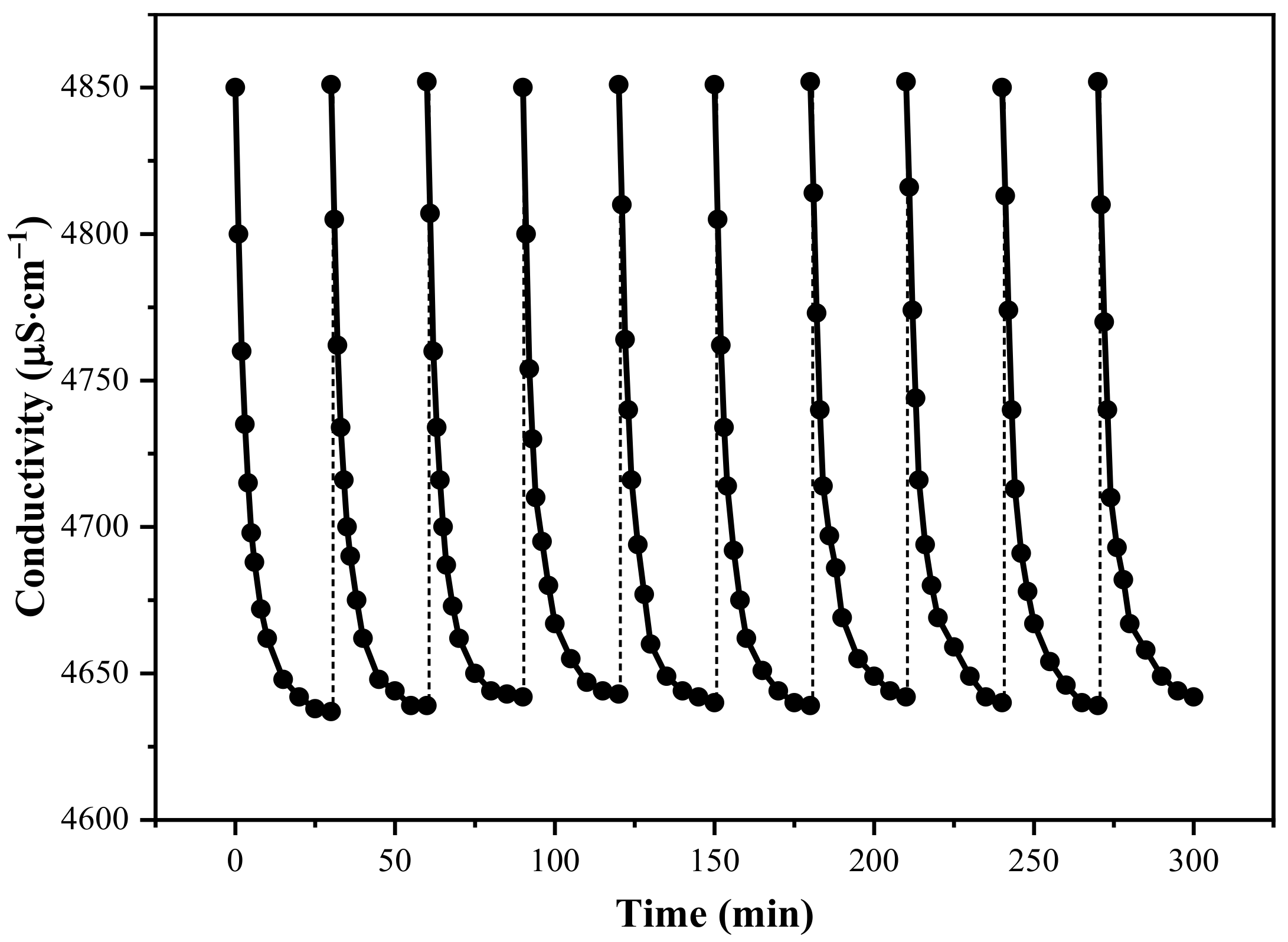
The adsorption–regeneration experiments were repeated for 10 cycles under the same experimental conditions to investigate the repeatability of the NMCS electrode. An amount of 1000 mg L−1 of the initial fluorine concentration and 1.2 V of constant voltage were employed. As shown in Figure 7, more than 94% of electrosorption capacity in the initial cycle was retained after 10 cycles, indicating the outstanding cycling stability of the NMCS electrode. In the cycling experiments, the effluent pH was constant at around 7.0. This implies that faradaic side reactions such as water splitting did not occur during the adsorption–regeneration cycling. After 10 adsorption–regeneration cycles, the NMCS electrode was taken out and characterized by TEM. As shown in Figure S6, the regular spherical morphology with distinct core-shell structure was completely retained, further revealing the remarkable stability of NMCS during adsorption–regeneration cycling. The superior CDI performance outlined and discussed above demonstrates that NMCS would be a promising electrode material for effective defluorination.
4. Conclusions
In this study, we prepared NMCS via a gradient sol-gel method to effectively remove fluorine in CDI systems. NMCS achieved a high electrosorption capacity of 13.34 mg g−1 with the initial fluorine concentration of 1000 mg L−1 at 1.2 V and also excellent repeatability with little decrease of electrosorption capacity after 10 cycles. The superior defluorination performance of NMCS as compared with its undoped counterpart was associated with improved physicochemical properties, such as conductivity and wettability, the amelioration of pore structure and the transformation of morphology due to nitrogen doping. Nitrogen doping into NMCS was found to not only facilitate ion transportation, but to also improve the available adsorption sites. Therefore, NMCS would be an excellent electrode material for effective defluorination in CDI systems.
Supplementary Materials
The following supporting information can be downloaded at: https://www.mdpi.com/article/10.3390/w15030608/s1, Figure S1: Schematic diagram of the defluorination system (a) and the CDI unit (b); Figure S2: Standard curve of conductivity and fluorine concentration; Figure S3: EDS elemental mapping images equipped with TEM of NMCS; Figure S4: The water contact angle of MCS (a) and NMCS (b); Figure S5: Conductivity change of circulating solution of MCS (a) and NMCS (b) with different initial fluorine concentrations; conductivity change of circulating solution of MCS (c) and NMCS (d) with different voltages; Figure S6: TEM image of NMCS after 10 adsorption–regeneration cycles; Table S1: Comparison of defluorination capacity and time between NMCS and reported materials in the literature.
Author Contributions
Y.Z.: methodology, original draft preparation, funding acquisition. K.L.: conceptualization, reviewing and editing. B.S.: reviewing and editing. F.C.: supervision, review and editing, funding acquisition. Y.S.: methodology, data curation, reviewing and editing. All authors have read and agreed to the published version of the manuscript.
Funding
This research was funded by Shandong Provincial Natural Science Foundation (No. ZR2022QE088), Shandong Postdoctora1 Science Foundation (No. SDCX-ZG-202202028), Shandong Top Talent Special Foundation, Doctoral Research Fund Project in Shandong Jianzhu University (No. X22005Z), National Key Research and Development Program of China (No. 2022YFE0105800), Nanxun Collaborative Innovation Center Key Research Project (No. JZ2022ZH01).
Data Availability Statement
All data that support the findings of this study are available from the corresponding author upon reasonable request.
Conflicts of Interest
The authors declare no conflict of interest.
References
- Smith, G.E. Fluoride, the environment, and human health. Perspect. Biol. Med. 1986, 29, 560–572. [Google Scholar] [CrossRef] [PubMed]
- Wang, M.; Li, X.; He, W.; Li, J.; Zhu, Y.; Liao, Y.; Yang, J.; Yang, X. Distribution, health risk assessment, and anthropogenic sources of fluoride in farmland soils in phosphate industrial area, southwest China. Environ. Pollut. 2019, 249, 423–433. [Google Scholar] [CrossRef] [PubMed]
- Wan, K.; Huang, L.; Yan, J.; Ma, B.; Huang, X.; Luo, Z.; Zhang, H.; Xiao, T. Removal of fluoride from industrial wastewater by using different adsorbents: A review. Sci. Total Environ. 2021, 773, 145535. [Google Scholar] [CrossRef] [PubMed]
- Velazquez-Jimenez, L.H.; Vences-Alvarez, E.; Flores-Arciniega, J.L.; Flores-Zuñiga, H.; Rangel-Mendez, J.R. Water defluoridation with special emphasis on adsorbents-containing metal oxides and/or hydroxides: A review. Sep. Purif. Technol. 2015, 150, 292–307. [Google Scholar] [CrossRef]
- Wu, Q.; Liang, D.; Lu, S.; Wang, H.; Xiang, Y.; Aurbach, D.; Avraham, E.; Cohen, I. Advances and perspectives in integrated membrane capacitive deionization for water desalination. Desalination 2022, 542, 116043. [Google Scholar] [CrossRef]
- Nunes-Pereira, J.; Lima, R.; Choudhary, G.; Sharma, P.R.; Ferdov, S.; Botelho, G.; Sharma, R.K.; Lanceros-Méndez, S. Highly efficient removal of fluoride from aqueous media through polymer composite membranes. Sep. Purif. Technol. 2018, 205, 1–10. [Google Scholar] [CrossRef]
- Pan, B.; Xu, J.; Wu, B.; Li, Z.; Liu, X. Enhanced removal of fluoride by polystyrene anion exchanger supported hydrous zirconium oxide nanoparticles. Environ. Sci. Technol. 2013, 47, 9347–9354. [Google Scholar] [CrossRef]
- Nordstrand, J.; Dutta, J. Theory of bipolar connections in capacitive deionization and principles of structural design. Electrochim. Acta 2022, 430, 141066. [Google Scholar] [CrossRef]
- Wang, R.; Sun, K.; Zhang, Y.; Qian, C.; Bao, W. Dimensional optimization enables high-performance capacitive deionization. J. Mater. Chem. A 2022, 10, 6414–6441. [Google Scholar] [CrossRef]
- Hu, C.-C.; Hsieh, C.-F.; Chen, Y.-J.; Liu, C.-F. How to achieve the optimal performance of capacitive deionization and inverted-capacitive deionization. Desalination 2018, 442, 89–98. [Google Scholar] [CrossRef]
- Suss, M.E.; Porada, S.; Sun, X.; Biesheuvel, P.M.; Yoon, J.; Presser, V. Water desalination via capacitive deionization: What is it and what can we expect from it? Energy Environ. Sci. 2015, 8, 2296–2319. [Google Scholar] [CrossRef]
- Tang, W.; Kovalsky, P.; He, D.; Waite, T.D. Fluoride and nitrate removal from brackish groundwaters by batch-mode capacitive deionization. Water Res. 2015, 84, 342–349. [Google Scholar] [CrossRef]
- Epshtein, A.; Nir, O.; Monat, L.; Gendel, Y. Treatment of acidic wastewater via fluoride ions removal by SiO2 particles followed by phosphate ions recovery using flow-electrode capacitive deionization. Chem. Eng. J. 2020, 400, 125892. [Google Scholar] [CrossRef]
- Gaikwad, M.S.; Balomajumder, C. Simultaneous electrosorptive removal of chromium(VI) and fluoride ions by capacitive deionization (CDI): Multicomponent isotherm modeling and kinetic study. Sep. Purif. Technol. 2017, 186, 272–281. [Google Scholar] [CrossRef]
- Park, G.; Hong, S.P.; Lee, C.; Lee, J.; Yoon, J. Selective fluoride removal in capacitive deionization by reduced graphene oxide/hydroxyapatite composite electrode. J. Colloid Interface Sci. 2012, 581, 396–402. [Google Scholar] [CrossRef]
- Tang, W.; Kovalsky, P.; Cao, B.; Waite, T.D. Investigation of fluoride removal from low-salinity groundwater by single-pass constant-voltage capacitive deionization. Water Res. 2016, 99, 112–121. [Google Scholar] [CrossRef]
- Gaikwad, M.S.; Balomajumder, C. Tea waste biomass activated carbon electrode for simultaneous removal of Cr(VI) and fluoride by capacitive deionization. Chemosphere 2017, 184, 1141–1149. [Google Scholar] [CrossRef]
- Xu, X.; Tan, H.; Wang, Z.; Wang, C.; Pan, L.; Kaneti, Y.V.; Yang, T.; Yamauchi, Y. Extraordinary capacitive deionization performance of highly-ordered mesoporous carbon nanopolyhedra for brackish water desalination. Environ. Sci. Nano 2019, 6, 981. [Google Scholar] [CrossRef]
- Wang, H.; Wei, D.; Gang, H.; He, Y.; Zhang, L. Hierarchical porous carbon from synergistic “pore-on-pore” strategy for efficient capacitive deionization. ACS Sustain. Chem. Eng. 2020, 8, 1129–1136. [Google Scholar] [CrossRef]
- Baroud, T.N.; Giannelis, E.P. High salt capacity and high removal rate capacitive deionization enabled by hierarchical porous carbons. Carbon 2018, 139, 614–625. [Google Scholar] [CrossRef]
- Baroud, T.N.; Giannelis, E.P. Role of mesopore structure of hierarchical porous carbons on the electrosorption performance of capacitive deionization electrodes. ACS Sustain. Chem. Eng. 2019, 7, 7580–7596. [Google Scholar] [CrossRef]
- Gao, T.; Li, H.; Zhou, F.; Gao, M.; Liang, S.; Luo, M. Mesoporous carbon derived from ZIF-8 for high efficient electrosorption. Desalination 2019, 451, 133–138. [Google Scholar] [CrossRef]
- Li, Y.; Zhang, C.; Jiang, Y.; Wang, T.-J. Electrically enhanced adsorption and green regeneration for fluoride removal using Ti(OH)4-loaded activated carbon electrodes. Chemosphere 2018, 200, 554–560. [Google Scholar] [CrossRef] [PubMed]
- Martinez-Vargas, D.R.; Rangel-Mendez, J.R.; Chazaro-Ruiz, L.F. Fluoride electrosorption by hybrid La(III)-activated carbon electrodes under the influence of the La(III) content and the polarization profile. J. Environ. Chem. Eng. 2022, 10, 106926. [Google Scholar] [CrossRef]
- Martinez-Vargas, D.R.; Larios-Dur’an, E.R.; Chazaro-Ruiz, L.F.; Rangel-Mendez, J.R. Correlation between physicochemical and electrochemical properties of an activated carbon doped with lanthanum for fluoride electrosorption. Sep. Purif. Technol. 2021, 268, 118702. [Google Scholar] [CrossRef]
- Wu, P.; Xia, L.; Dai, M.; Lin, L.; Song, S. Electrosorption of fluoride on TiO2-loaded activated carbon in water. Colloids Surf. A Physicochem. Eng. Asp. 2016, 502, 66–73. [Google Scholar] [CrossRef]
- He, D.; Niu, J.; Dou, M.; Ji, J.; Huang, Y.; Wang, F. Nitrogen and oxygen co-doped carbon networks with a mesopore-dominant hierarchical porosity for high energy and power density supercapacitors. Electrochim. Acta 2017, 238, 310–318. [Google Scholar] [CrossRef]
- Zhao, Y.; Zhang, Y.; Tian, P.; Wang, L.; Li, K.; Lv, C.; Liang, B. Nitrogen-rich mesoporous carbons derived from zeolitic imidazolate framework-8 for efficient capacitive deionization. Electrochim. Acta 2019, 321, 134665. [Google Scholar] [CrossRef]
- Zong, M.; Zhang, Y.; Li, K.; Lv, C.; Tian, P.; Zhao, Y.; Liang, B. Zeolitic imidazolate framework-8 derived two-dimensional N-doped amorphous mesoporous carbon nanosheets for efficient capacitive deionization. Electrochim. Acta 2020, 329, 135089. [Google Scholar] [CrossRef]
- Yang, L.; Hussain, I.; Qi, J.; Chao, L.; Li, J.; Shen, J.; Sun, X.; Han, W.; Wang, L. N-doped hierarchical porous carbon derived from hypercrosslinked diblock copolymer for capacitive deionization. Sep. Purif. Technol. 2016, 165, 190–198. [Google Scholar]
- Yan, T.; Liu, J.; Lei, H.; Shi, L.; Zhang, D. Capacitive deionization of saline water using sandwich-like nitrogen-doped graphene composites via a self-assembling strategy. Environ. Sci. Nano 2018, 5, 2722–2730. [Google Scholar] [CrossRef]
- Zhang, W.; Xu, J.; Hou, D.; Yin, J.; Liu, D.; He, Y. Hierarchical porous carbon prepared from biomass through a facile method for supercapacitor applications. J. Colloid Interface Sci. 2018, 530, 338–344. [Google Scholar] [CrossRef]
- Wang, K.; Xu, M.; Gu, Y.; Gu, Z.; Fan, Q.H. Symmetric supercapacitors using urea-modified lignin derived N-doped porous carbon as electrode materials in liquid and solid electrolytes. J. Power Sources 2016, 332, 180–186. [Google Scholar] [CrossRef]
- Gao, T.; Du, Y.; Li, H. Preparation of nitrogen-doped graphitic porous carbon towards capacitive deionization with high adsorption capacity and rate capability. Sep. Purif. Technol. 2015, 165, 190–198. [Google Scholar] [CrossRef]
- Li, G.-X.; Hou, P.-X.; Zhao, S.-Y.; Liu, C.; Cheng, H.-M. A flexible cotton-derived carbon sponge for high-performance capacitive deionization. Carbon 2016, 101, 1–8. [Google Scholar] [CrossRef]
- Wang, Z.; Yan, T.; Fang, J.; Shi, L.; Zhang, D. Nitrogen-doped porous carbon derived from a bimetallic metal-organic framework as highly efficient electrodes for flow-through deionization capacitors. J. Mater. Chem. A 2016, 4, 10858–10868. [Google Scholar] [CrossRef]
- Chang, L.; Hu, Y.H. 3D Channel-structured graphene as efficient electrodes for capacitive deionization. J. Colloid Interface Sci. 2019, 538, 420–425. [Google Scholar] [CrossRef]
- Vinayan, B.P.; Nagar, R.; Raman, V.; Rajalakshmi, N.; Dhathathreyan, K.S.; Pamaprabhu, S. Synthesis of graphene-multiwalled carbon nanotubes hybrid nanostructure by strengthened electrostatic interaction and its lithium ion battery application. J. Mater. Chem. 2012, 22, 9949–9956. [Google Scholar] [CrossRef]
- Liu, Y.; Chen, T.; Lu, T.; Sun, Z.; Chua, D.H.C.; Pan, L. Nitrogen-doped porous carbon spheres for highly efficient capacitive deionization. Electrochim. Acta 2015, 158, 403–409. [Google Scholar] [CrossRef]
- Lin, Z.; Waller, G.; Liu, Y.; Liu, M.; Wong, C.-P. Facile synthesis of nitrogen-doped graphene via pyrolysis of graphene oxide and urea, and its electrocatalytic activity toward the oxygen-reduction reaction. Adv. Energy Mater. 2012, 2, 884–888. [Google Scholar] [CrossRef]
- Tang, Y.; Zheng, S.; Cao, S.; Yang, F.; Guo, X.; Zhang, S.; Xue, H.; Pang, H. Hollow mesoporous carbon nanospheres space-confining ultrathin nanosheets superstructures for efficient capacitive deionization. J. Colloid Interface Sci. 2022, 626, 1062–1069. [Google Scholar] [CrossRef] [PubMed]
- Zhang, W.; Liu, Y.; Jin, C.; Shi, Z.; Zhu, L.; Zhang, H.; Jiang, L.; Chen, L. Efficient capacitive deionization with 2D/3D heterostructured carbon electrode derived from chitosan and g-C3N4 nanosheets. Desalination 2022, 538, 115933. [Google Scholar] [CrossRef]
- Li, Y.; Jiang, Y.; Wang, T.-J.; Zhang, C.; Wang, H. Performance of fluoride electrosorption using micropore-dominant activated carbon as an electrode. Sep. Purif. Technol. 2017, 172, 415–421. [Google Scholar] [CrossRef]
- Xu, B.; Wang, R.; Fan, Y.; Li, B.; Zhang, J.; Peng, F.; Du, Y.; Yang, W. Flexible self-supporting electrode for high removal performance of arsenic by capacitive deionization. Sep. Purif. Technol. 2022, 299, 121732. [Google Scholar] [CrossRef]
- Gaikwad, M.S.; Balomajumder, C. Removal of Cr(VI) and fluoride by membrane capacitive deionization with nanoporous and microporous Limonia acidissima (wood apple) shell activated carbon electrode. Sep. Purif. Technol. 2018, 195, 305–313. [Google Scholar] [CrossRef]
Figure 1.
(a) SEM image of MCS; (b) SEM image of NMCS; (c) TEM image of MCS; (d) TEM image of NMCS; (e–g) high-resolution TEM images of NMCS.
Figure 1.
(a) SEM image of MCS; (b) SEM image of NMCS; (c) TEM image of MCS; (d) TEM image of NMCS; (e–g) high-resolution TEM images of NMCS.

Figure 2.
(a) Raman spectra of MCS and NMCS; (b) N2 adsorption/desorption isotherms of MCS and NMCS; (c) pore size distribution curves of MCS and NMCS.
Figure 2.
(a) Raman spectra of MCS and NMCS; (b) N2 adsorption/desorption isotherms of MCS and NMCS; (c) pore size distribution curves of MCS and NMCS.

Figure 3.
(a) FTIR spectra of MCS and NMCS; (b) XPS survey spectra of MCS and NMCS; (c) high-resolution N1s spectra of MCS; (d) high-resolution N1s spectra of NMCS.
Figure 3.
(a) FTIR spectra of MCS and NMCS; (b) XPS survey spectra of MCS and NMCS; (c) high-resolution N1s spectra of MCS; (d) high-resolution N1s spectra of NMCS.

Figure 4.
(a) CV curves of MCS with different scan rates; (b) CV curves of NMCS with different scan rates; (c) specific capacitance results of MCS and NMCS; (d) GCD curves of MCS with different current densities; (e) GCD curves of NMCS with different current densities; (f) charge/discharge capacitance results of MCS and NMCS.

Figure 5.
EIS curves of MCS and NMCS.

Figure 6.
(a) Conductivity change of circulating solution of MCS and NMCS with the initial fluorine concentration of 1000 mg L−1 at 1.2 V; (b) the corresponding Kim plots of MCS and NMCS with the initial fluorine concentration of 1000 mg L−1 at 1.2 V; (c) electrosorption capacity of MCS and NMCS with different initial fluorine concentrations; (d) electrosorption capacity of MCS and NMCS with different voltages.

Figure 7.
Cycling stability of NMCS.


Table 1.
Pore structural parameters of MCS and NMCS.
| Sample | Specific Surface Area (m2 g−1) | Pore Volume (cm3 g−1) | ||||
|---|---|---|---|---|---|---|
| SBET | Smic | Smeso | Vt | Vmic | Vmeso | |
| MCS | 1058 | 287 | 771 | 1.89 | 0.12 | 1.77 |
| NMCS | 1049 | 230 | 819 | 1.78 | 0.10 | 1.68 |
Table 2.
Nitrogen content of MCS and NMCS.
| Sample | N (%) | Fraction of Nitrogen (%) | Content of Nitrogen (%) | ||||
|---|---|---|---|---|---|---|---|
| Pyridinic-N | Pyrrolic-N | Graphitic-N | Pyridinic-N | Pyrrolic-N | Graphitic-N | ||
| MCS | 0.31 | 1058 | 287 | 771 | 1.89 | 0.12 | 1.77 |
| NMCS | 4.03 | 1049 | 230 | 819 | 1.78 | 0.10 | 1.68 |
Disclaimer/Publisher’s Note: The statements, opinions and data contained in all publications are solely those of the individual author(s) and contributor(s) and not of MDPI and/or the editor(s). MDPI and/or the editor(s) disclaim responsibility for any injury to people or property resulting from any ideas, methods, instructions or products referred to in the content. |
© 2023 by the authors. Licensee MDPI, Basel, Switzerland. This article is an open access article distributed under the terms and conditions of the Creative Commons Attribution (CC BY) license (https://creativecommons.org/licenses/by/4.0/).
Share and Cite
MDPI and ACS Style
Zhao, Y.; Li, K.; Sheng, B.; Chen, F.; Song, Y. Nitrogen-Doped Core-Shell Mesoporous Carbonaceous Nanospheres for Effective Removal of Fluorine in Capacitive Deionization. Water 2023, 15, 608. https://doi.org/10.3390/w15030608
AMA Style
Zhao Y, Li K, Sheng B, Chen F, Song Y. Nitrogen-Doped Core-Shell Mesoporous Carbonaceous Nanospheres for Effective Removal of Fluorine in Capacitive Deionization. Water. 2023; 15(3):608. https://doi.org/10.3390/w15030608
Chicago/Turabian StyleZhao, Yubo, Kexun Li, Bangsong Sheng, Feiyong Chen, and Yang Song. 2023. "Nitrogen-Doped Core-Shell Mesoporous Carbonaceous Nanospheres for Effective Removal of Fluorine in Capacitive Deionization" Water 15, no. 3: 608. https://doi.org/10.3390/w15030608
Note that from the first issue of 2016, this journal uses article numbers instead of page numbers. See further details here.