
Vibration Characteristics of a Tubular Turbine Prototype at Different Heads with Considering Free Surface and Water Gravity
Institute of Water Resources and Hydropower, Xi’an University of Technology, Xi’an 710048, China
*
Author to whom correspondence should be addressed.
Water 2023, 15(4), 791; https://doi.org/10.3390/w15040791
Submission received: 4 January 2023
/
Revised: 14 February 2023
/
Accepted: 15 February 2023
/
Published: 17 February 2023
(This article belongs to the Section Hydraulics and Hydrodynamics)
Abstract
:Tubular turbines are widely used in low water head and tidal power development due to their straight flow path, simple structure, and wide efficient area. However, the severe vibration during actual operation greatly affects the safe operation of the tubular turbine. This study performs a numerical calculation of the tubular turbine, which meets the actual machine conditions considering the free surface and water gravity; compares and analyzes the flow characteristics and pressure fluctuation spectrum characteristics in the tubular turbine under different water heads; and verifies the comparison with the actual machine test results to explore the vibration characteristics and vibration mechanism of the tubular turbine. Research results show that a large pressure difference is observed between the top and bottom of the runner chamber, and the runner needs to experience large periodic pressure fluctuations during rotation due to the combined effect of hydrostatic pressure and hydrodynamic pressure. Under different water heads, obvious flow turbulence and high turbulent kinetic energy areas are observed in the runner and draft tube due to the influence of the shape of the blade wake vortex. The vibration in the tubular turbine is mainly concentrated in the runner and draft tube and influenced by the water gravity and the runner structure of the transverse cantilever beam. The amplitude of pressure fluctuation is the largest when the frequency inside the runner is the blade passing frequency at each water head, so the maximum vibration position is located at the runner. The research results serve as a guide for the design and operation of the horizontal tubular turbine.
1. Introduction
The tubular turbine is characterized by a straight flow passage, large flow, high efficiency, and compact structure, so it has obvious advantages in the development of low-head hydraulic resources. The special structure of the tubular turbine makes its operation performance different from other conventional units, particularly severe vibration, which has become an important factor limiting the safe operation of ultralow-head tubular turbines [1,2,3,4]. Water body fluctuation in the reservoir area of the tubular power plant, vibration induced by water gravity, and periodic pressure fluctuation generated during turbine operation are coupled and combined, which make the vibration inside the turbine more complex. The vibration of the tubular unit mainly occurs in a low-head operation and a high-head operation with a partial load [5], and the simple structural form of support [6] makes it prone to structural deformation during operation and causes the axial asymmetry of water flow inside the turbine. The nonuniformity of cavitation causes hydraulic imbalance because the cavitation area of the tubular turbine is mainly concentrated at the top of the runner chamber [7]. The pressure pulsation caused by the clearance jet from the rim changes from high pressure to low pressure with the rotation of the unit, forming periodic pressure pulsation. Various pressure pulsations occur after the unit loses its optimum coordination [8]. Hydrostatic pressure difference causes a hydraulic balance in water flow, causing the vibration of the turbine. At the same time, different hydrostatic pressure differences experienced during blade rotation make the blades subject to alternating stress, which is prone to deformation and cracks [9].
Research on the tubular turbine mainly takes the model turbine as the research object and analyzes the internal flow characteristics [10,11,12], optimum design [13], and stability [14,15,16] of the tubular turbine through a model test and numerical simulation, which greatly improves the overall operation performance of the tubular turbine. However, a long consensus is established on the performance differences between the prototype and model turbines of tubular turbines and the reasons for these differences. Zhen et al. [17] pointed out that the flow rate and efficiency of the prototype turbine could not be accurately measured in 1989. However, remarkable differences are observed between the actual results and the results calculated using the traditional conversion formula by comparing the power of the prototype and model of the bulb unit. Considering that the real turbine test is difficult to achieve, some scholars have begun to study the real turbine performance of the tubular turbine by means of a numerical simulation in recent years. Liu and Chane [18] performed a numerical calculation for the tubular turbine considering the gravity field and found that the gravity field has a remarkable influence on the average flow rate and flow rate of the inlet section during the operation of the low-head turbine. The pressure inside the runner chamber gradually increases in the direction of gravity. During periodic operation, the blade torque changes accordingly, causing periodic disturbance and dynamic oscillation. Feng et al. [19] established a performance analysis model of the bidirectional tubular turbine under the second-order Stokes nonlinear tidal boundary and studied the influence of a dynamic wave–current boundary on the hydraulic characteristics of a bidirectional tubular turbine during operation via computational fluid dynamics. Xu et al. [20] analyzed and demonstrated the relationship between gap cavitation and pressure fluctuation at a high-speed frequency by combining a theoretical analysis with the original and model test verification. In the previous study, the author conducted a numerical study on the real horizontal tubular turbine considering the influence of the free liquid level and hydraulic force in accordance with actual boundary conditions and performed an in-depth study of the difference in the internal flow state of the tubular turbine when considering the free surface and water gravity [21], the stress–strain distribution rule of tubular turbine blade when considering free surface and water gravity conditions [22], and the pressure fluctuation analysis of the tubular turbine in different head sections [23]. The results obtained are highly consistent with the actual situation. However, many studies only reveal the internal flow state and vibration characteristics of the tubular turbine under real turbine conditions and do not systematically analyze the fundamental reasons for the difference in flow state and the basic generating mechanism of different vibration characteristics of the tubular turbine under different operating conditions [24].
The running performance of the tubular turbine is different from that of the conventional vertical shaft turbine due to the characteristics of the horizontal flow passage arrangement, short inlet section of unit, vertical flow direction, and gravity direction. The operation of many power stations shows that severe vibration occurs frequently in the operation of low-head tubular power stations. In addition to the hydraulic imbalance, low-frequency pressure pulsation of the tailpipe, cavity cavitation, Karman vortex train, and clearance jet common to conventional power stations, there are also some factors unique to ultra-low-head tubular units; for example, the potential structural instability of the runner in the form of the cantilever beam, the vibration induced by the poor axial symmetry of hydraulic elements caused by hydrostatic pressure difference, and the vibration induced by the fluctuation of the free liquid level in the reservoir area, etc. The previous research is based on the model machine and the performance of the tubular turbine unit is no different from that of the conventional vertical turbine unit. The unique flow characteristics of horizontal tubular units cannot be reflected. In this study, the influence of the free surface and water gravity on the internal flow characteristics of the unit is fully considered, and the real mechanical performance of the horizontal tubular unit is studied numerically. The research results obtained are more close to the real situation. This study takes a horizontal tubular hydropower station as an example to address the severe vibration during its actual operation, conducts a numerical study on the tubular turbines under different heads under the condition of free surface and water gravity, and analyzes the flow characteristics and pressure fluctuation spectrum characteristics inside the tubular turbines under different heads. This process is performed to reveal the vibration characteristics of the tubular turbine under different water heads and the variation law of its vibration mechanism with the water head and provide certain theoretical guidance for the design and operation of the horizontal tubular turbine.
2. Numerical Calculation Method
2.1. Geometric Model and Mesh Generation
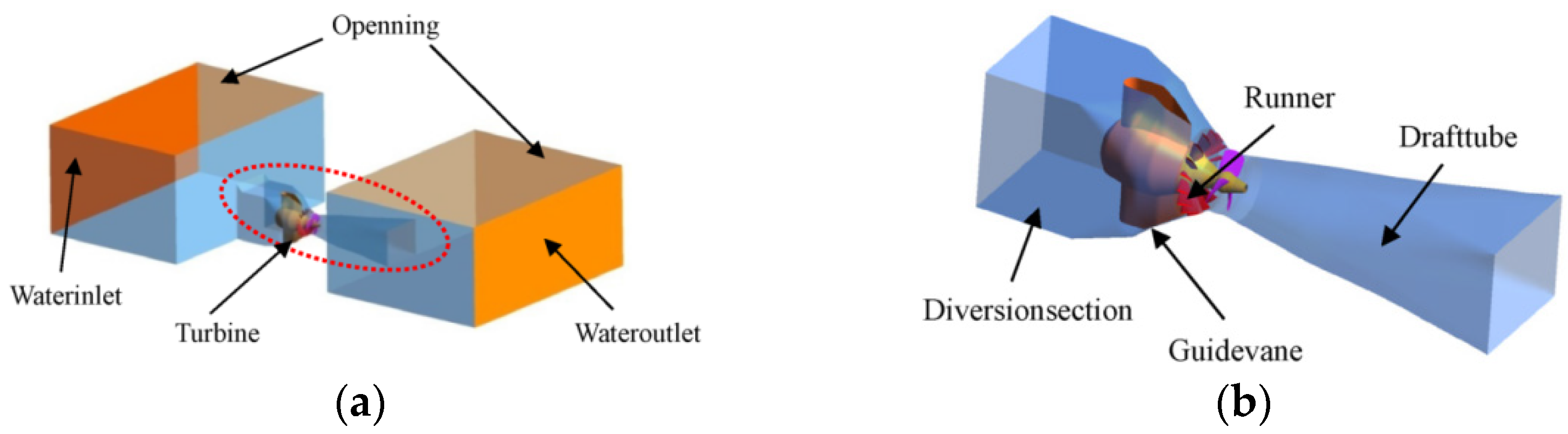
The basic parameters of the tubular turbine investigated in this study are as follows: runner diameter D1 = 7.2 m, the number of blades Zb = 3, the number of guide vanes Zg = 16, hub ratio = 0.35, rated speed nr = 75 r/min, rated head Hr = 6.1 m, and rated discharge Qr = 413 m3/s. The calculation domain model of the bulb tubular turbine including the upstream and downstream reservoir areas should be selected when establishing the model to conform to the actual situation. The calculation domain selected in this study includes the upstream reservoir area, diversion section, guide vane, runner, draft tube, and downstream reservoir area. The length of the upstream reservoir is 7.5D1, the length of the downstream reservoir is 8.5D1, and the width is 11D1. The specific geometric model is shown in Figure 1.
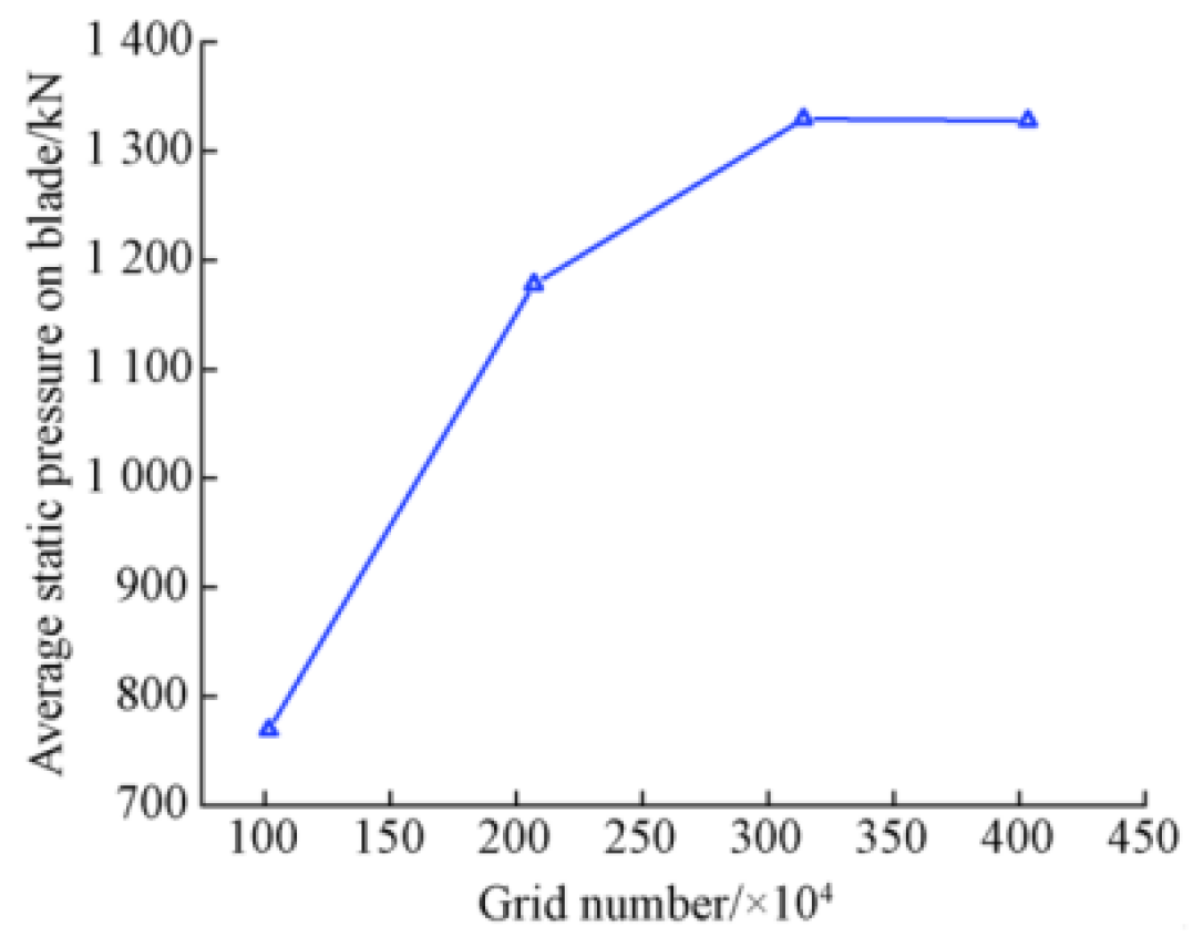
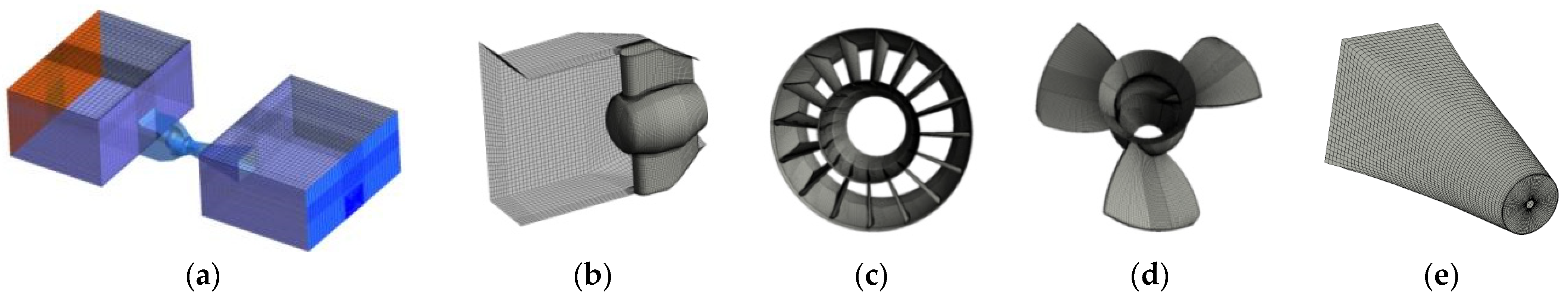
In this study, the hexahedral grids are used to discretize the whole computational domain. As shown in Figure 2, the horizontal coordinate is the number of grids, and the longitudinal coordinates are the average static pressure on the blade surface. On the basis of the verification results of grid independence, 3.14 million grids are selected as the grid number for numerical calculation. The computational domain grid is shown in Figure 3, where the number of grid units in the upstream reservoir area and diversion section is 6.67 × 10⁵, the number of guide vanes is 1.02 × 10⁶, runner is 1.04 × 10⁶, and the draft tube and downstream reservoir area is 4.14 × 10⁵.
2.2. Numerical Calculation Method and Validation
Continuity equation, momentum conservation equation, and energy conservation equations are the basic equations used to describe the flow regularity. Generally, water is regarded as an incompressible fluid flow, the heat exchange is very small, and the energy conservation is often ignored in the flow where water is taken as the medium. Based on these reasons, for the complex three-dimensional incompressible viscous flow in the turbine, the basic equations can be described using the continuity equation and momentum equation [24]:
where ρ is the density of fluid, kg/m3 τij is the shear stress of the fluid, N/m2; p is the pressure, Pa; ui and uj are the velocity components of the fluid, m/s; xi and xj are spatial coordinate components, m; and Sij is the additional source term, N/m3. Since the flow direction of the horizontal unit water flow is perpendicular to the direction of gravity, the influence of gravity on the internal flow field of the turbine needs to be considered in the numerical calculation, so the source term in the equation is defined as: Sij = ρg.
In this paper, the VOF model is used to solve the water–gas two-phase flow of the upstream and downstream free surface of the tubular turbine, and the transport diffusion equation of the volume function is established and solved to determine the location of the free surface. The relevant VOF equation is as follows:
where ui, uj is the velocity component of the fluid, m/s, α is the volume fraction of the fluid, α = 1 is the liquid phase, and α = 0 is the gas phase.
A turbulent model is introduced to close the equations because the average Navier–Stokes equation is not closed when describing turbulent motion. A standard k–ε turbulent model, which is simple, stable, economical, and relatively accurate, is used to solve the complex 3D incompressible flow in a turbine [25]. The volume of the fluid model is used to solve the water–gas two-phase flow at the free water level in the upstream and downstream reservoir areas of a tubular turbine.
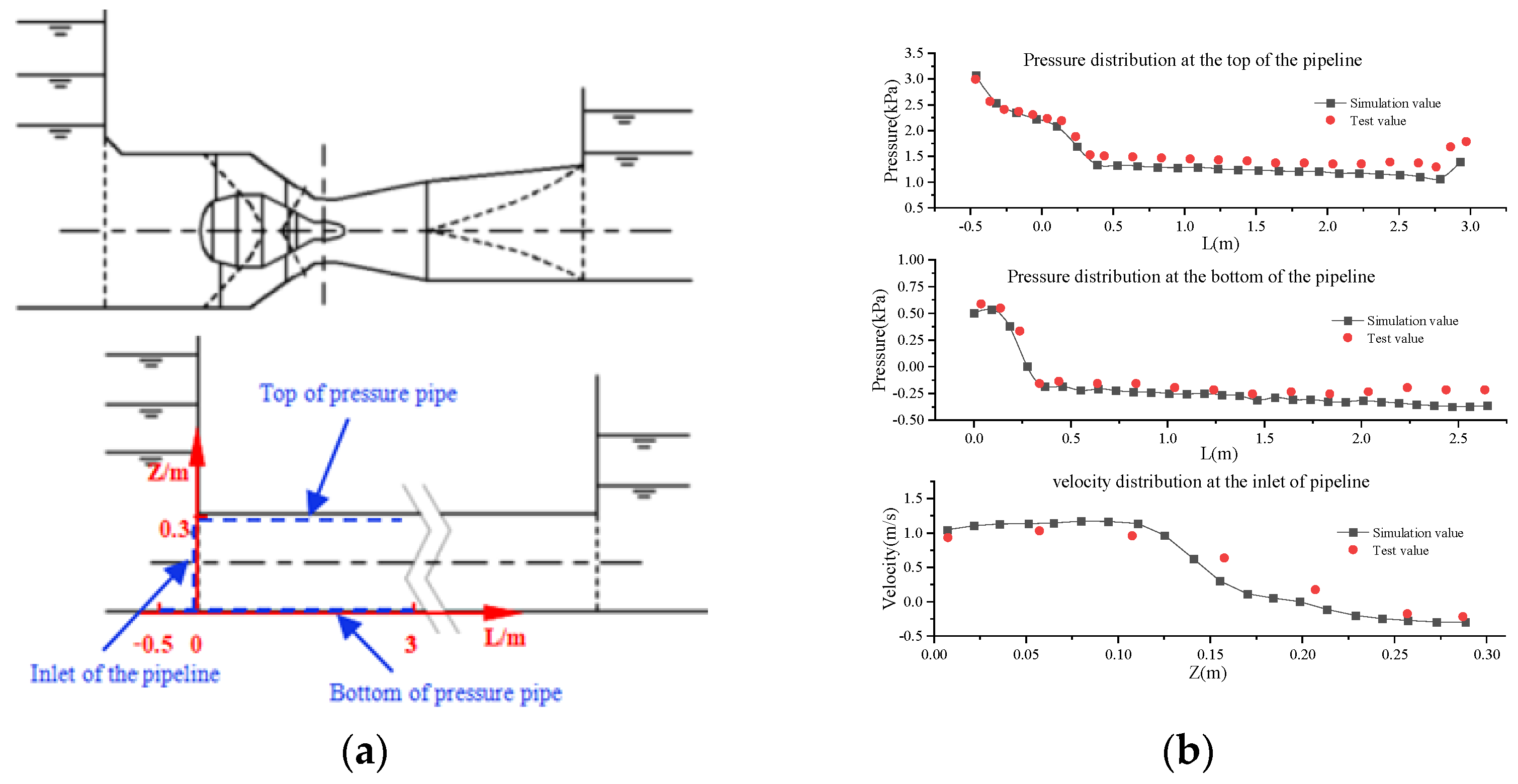
Whether the numerical calculation method is effective, reasonable, and has an important influence on the reliability of calculation results needs to be verified via experiment. Considering that the internal flow of a tubular turbine with a free surface is a combination of upstream and downstream open channel and pressure pipe flows, the author simplified the calculation domain into a pressurized pipe with upstream and downstream open water tanks in the previous study and conducted model tests to verify the feasibility of the above numerical simulation methods, as shown in Figure 4. The specific verification process is described in detail in reference [22]. Because the pressure pipeline ignores the energy conversion characteristics of the runner part, in the author’s previous study, the conversion values of the real machine output obtained via numerical simulation calculation and the test output under different working conditions of the tubular turbine were compared, and a good consistency was obtained [22]. This test accurately validates the feasibility of using this numerical research method to analyze the flow characteristics of a tubular turbine considering the free surface and water gravity.
2.3. Presentation of Boundary Conditions and Selection of Operating Point for Calculation
The numerical simulation method is used to study the real machine performance of the tubular turbine considering the free surface and water gravity in the upstream and downstream reservoir areas, and the boundary conditions are given as follows: as the tubular hydropower station is run by the river power station, the upstream water level remains unchanged, so a fixed liquid level and hydrostatic pressure are given. The corresponding liquid level height is given in accordance with different water heads in the downstream reservoir area. The top of the reservoir area is open surface with a zero-volume fraction of water. The rotating speed of the runner is set to 75 r/min in the runner area. All solid surfaces have no slip boundary. A “frozen rotor” is used at the interface between the guide vane and runner and between the runner and draft tube.
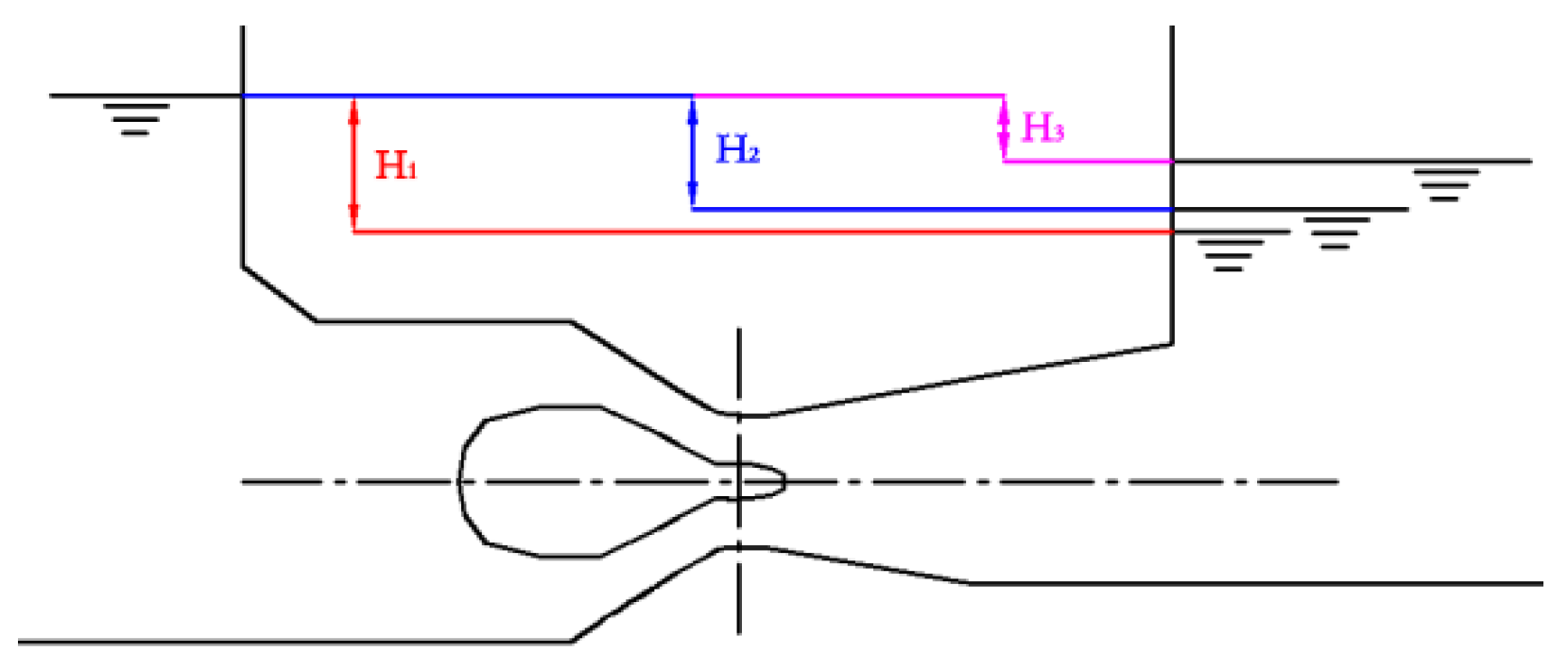
The upstream water level remains unchanged, and the downstream water level changes in accordance with the turbine flow under different conditions because the tubular power station is a runoff power station, which makes the working head of the turbine change, as shown in Figure 5, and H1–H3 are different head of water. The submergence depth of the runner differs when the tubular turbine is at different working heads, so the influence of hydrostatic pressure on turbine performance is also different. The condition points of different guide vane openings at the same blade angle are selected for the study to study the vibration characteristics of the bulb tubular turbines under different water heads with a consideration of the free surface and water gravity, and to avoid the interference of excessive flow difference on the analysis results. The specific parameters of the condition point are shown in Table 1.
3. Result Analysis
3.1. Distribution of Flow Characteristics in Tubular Turbine under Different Operating Conditions
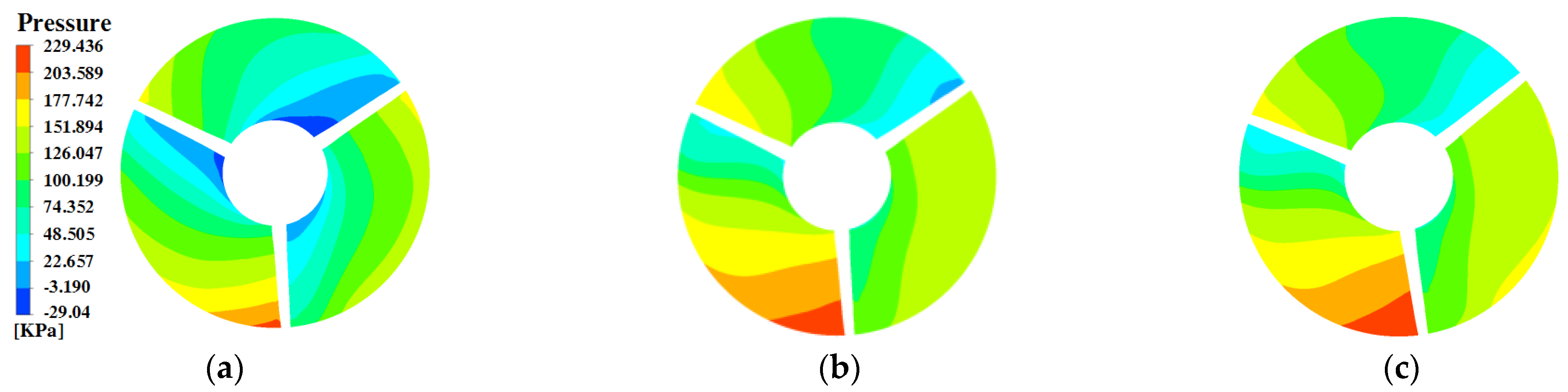
Figure 6 shows the pressure distribution in the middle section of a tubular turbine runner. The pressure distribution inside the runner shows obvious asymmetry under the combined action of hydrostatic pressure and water flow pressure. Condition one has a higher head and a smaller submergence depth for the turbine. When the blade rotates to the top of the runner chamber, the low pressure on the back of the blade superimposes the low pressure on the top of the runner chamber, which makes the blade prone to cavitation when it is turned to this position. With the increase in the head, the submergence depth of the runner decreases, and the hydrostatic pressure increases, causing the pressure to rise when the blades are turned to the top position of the runner chamber. Therefore, the cavitation performance of the turbine under low-head conditions is better than that under high-head conditions. With the decrease in the head and the increase in the submergence depth of the turbine, the relative pressure difference ΔH/H inside the runner changes. In condition one, the head is higher, the submergence depth of the turbine is small, and the relative pressure difference ΔH/H in the runner is 3.31. In condition two, the pressure difference in the runner is 3.45. In condition three, the head is lower, the submergence depth of the turbine is large, and the relative pressure difference in the runner is 4.46. During the rotating process of the runner, the large fluctuation in water pressure inside the runner inevitably affects the stability of the unit and causes fatigue damage of the blades when they overcome the large fluctuation in water pressure with the decrease in the water head.
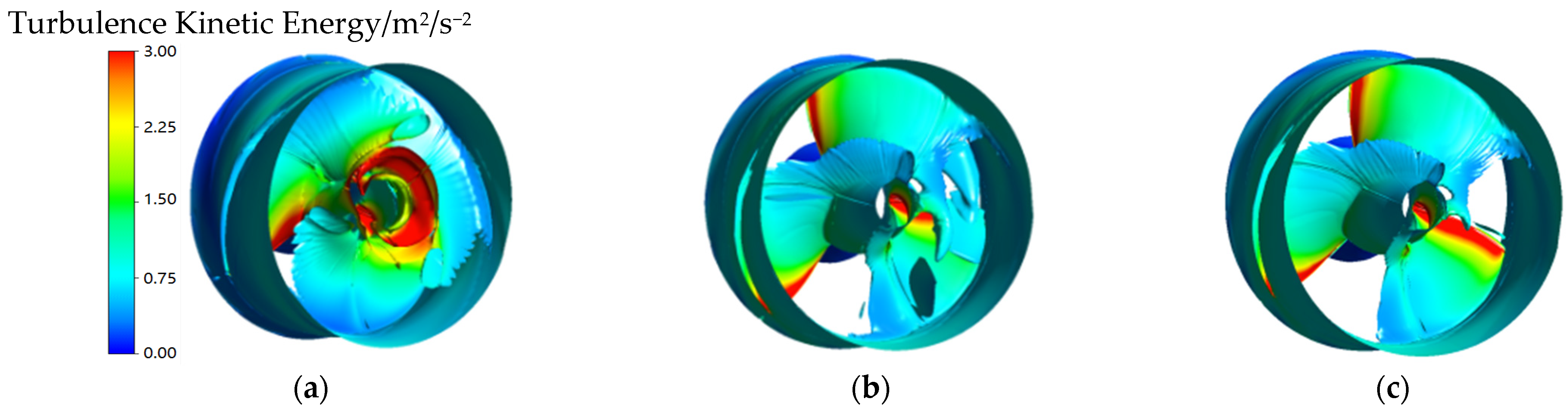
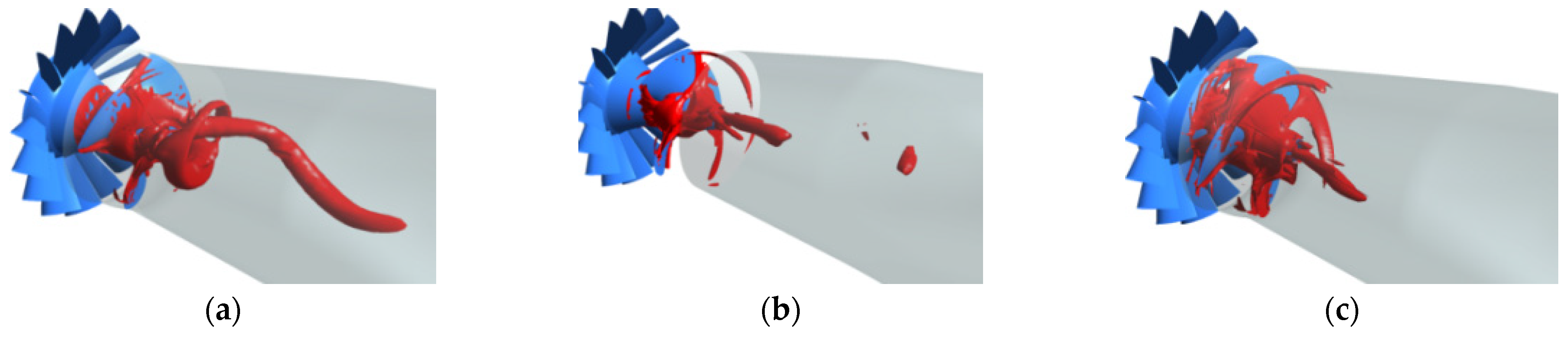
In order to clear and reflect the vortex state in the turbine, the identification of the vortex structure in the hydraulic turbine is plotted using the Q criterion. Figure 7 shows the vortex distribution and the strength of turbulent kinetic energy on the vortex structure in the runner of a tubular turbine, and Figure 8 shows the vorticity distribution in the draft tube of the turbine. From Figure 8, the water flow spoiled the blades and then formed an obvious wake vortex at the tailing edge of the blades. With the increase in the water head, the region of the eddy current in the runner becomes more complex, the volume of the eddy increases gradually, and the shape and distribution position of the wake vortices change remarkably. At higher water heads, blade wake vortices occur mainly in the middle of the flow path away from the hub and flow to the draft tube with a large degree of rotation. This high-swirl flow phenomenon can make the internal flow of the draft tube more disordered, with a distinct spiral draft tube vortex rope (Figure 8a), and can induce severe low-frequency pressure pulsations. With the decrease in the head, the wake vortices of the blades move toward the hub, mainly concentrating on the hub body at the tailing edge of the blade. When water flows out of the runner, the discharging cone converges and flows into the draft tube, which helps to improve the flow state in the draft tube (Figure 8b,c) and makes the spiral eddy band disappear in the draft tube, and only the cylindrical central eddy band with better stability appears.
As shown in the turbulent kinetic energy distribution in Figure 7, the high turbulent energy zone in the runner develops from the leading edge of the blade to the hub and the drain cone position with the high head under operating condition one. This condition is mainly because after the blade wake vortices deviate from the hub, an obvious return space is observed at the outlet of the runner, which intensifies the turbulence. With the decrease in the water head, the high turbulent energy area in the runner is mainly concentrated at the leading edge of the blade where the water flow strikes seriously. The high turbulent energy at the leading edge of the blade inevitably makes the flow in the runner more disordered and induces obvious vortices (Figure 8c).
3.2. Vibration Characteristics of Tubular Turbine
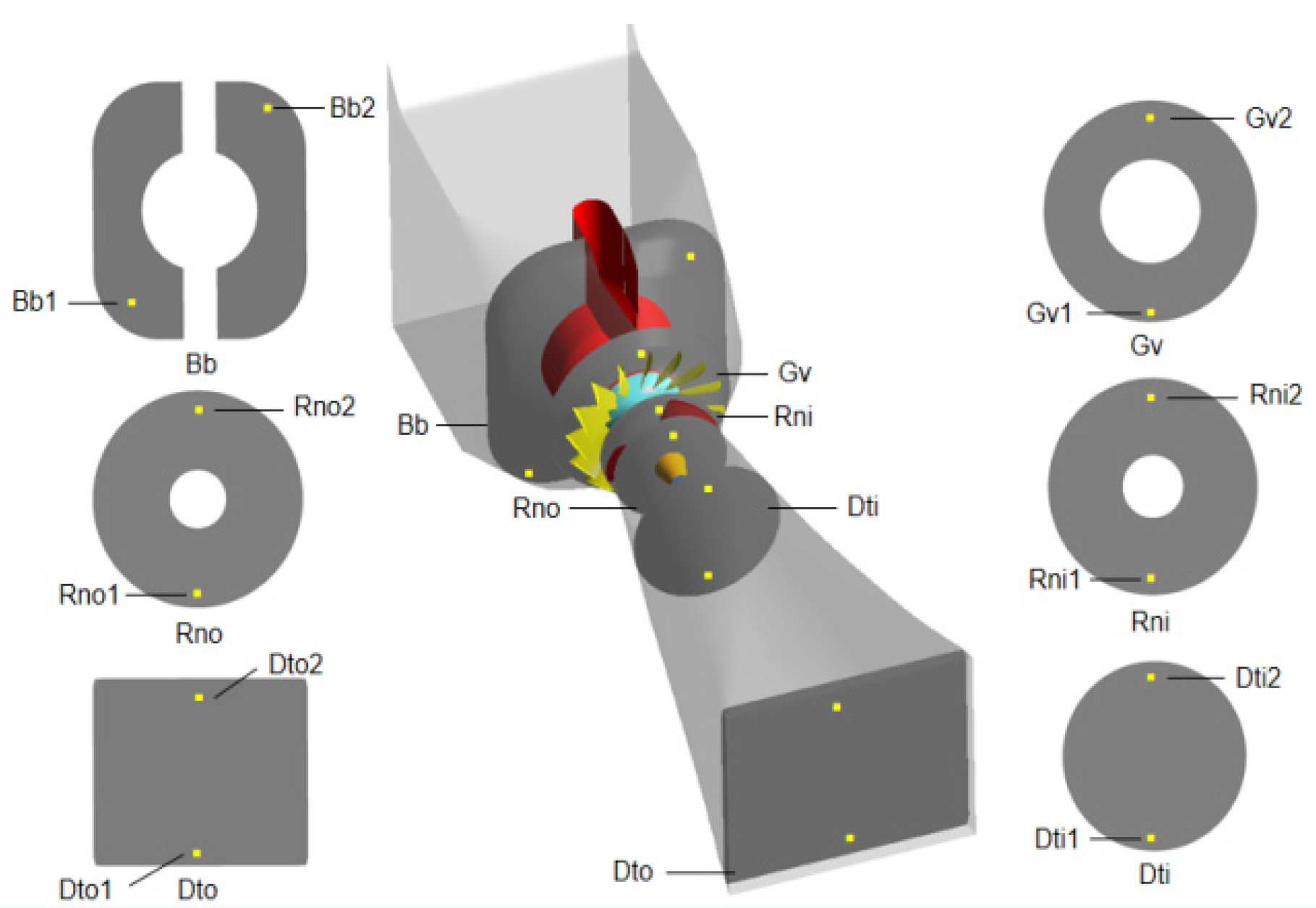
Pressure fluctuation detection is conducted on the important section of the main overflow component in the process of calculating the unsteady value of the tubular turbine to quantitatively analyze the unstable state inside each overflow component of the bulb tubular turbine, and the arrangement of the measuring points is shown in Figure 9. The measuring points are mainly located at the bulb body, guide vane inlet, runner inlet, runner outlet, draft tube inlet, and draft tube outlet. Pressure monitoring points are set at the top and bottom of each monitoring surface to study the influence of hydrostatic pressure on the internal pressure fluctuation of the turbine at different heights. The time interval of the sampling pressure fluctuation is 0.02 s, the sampling duration is 16 s, and the runner rotates for 20 cycles, which is enough to capture pressure pulsation at all frequencies. The hydraulic vibration characteristics in the turbine are analyzed through the fast Fourier transform of the pressure pulsation at the monitoring points considering the free surface of the upstream and downstream reservoirs and the water gravity.
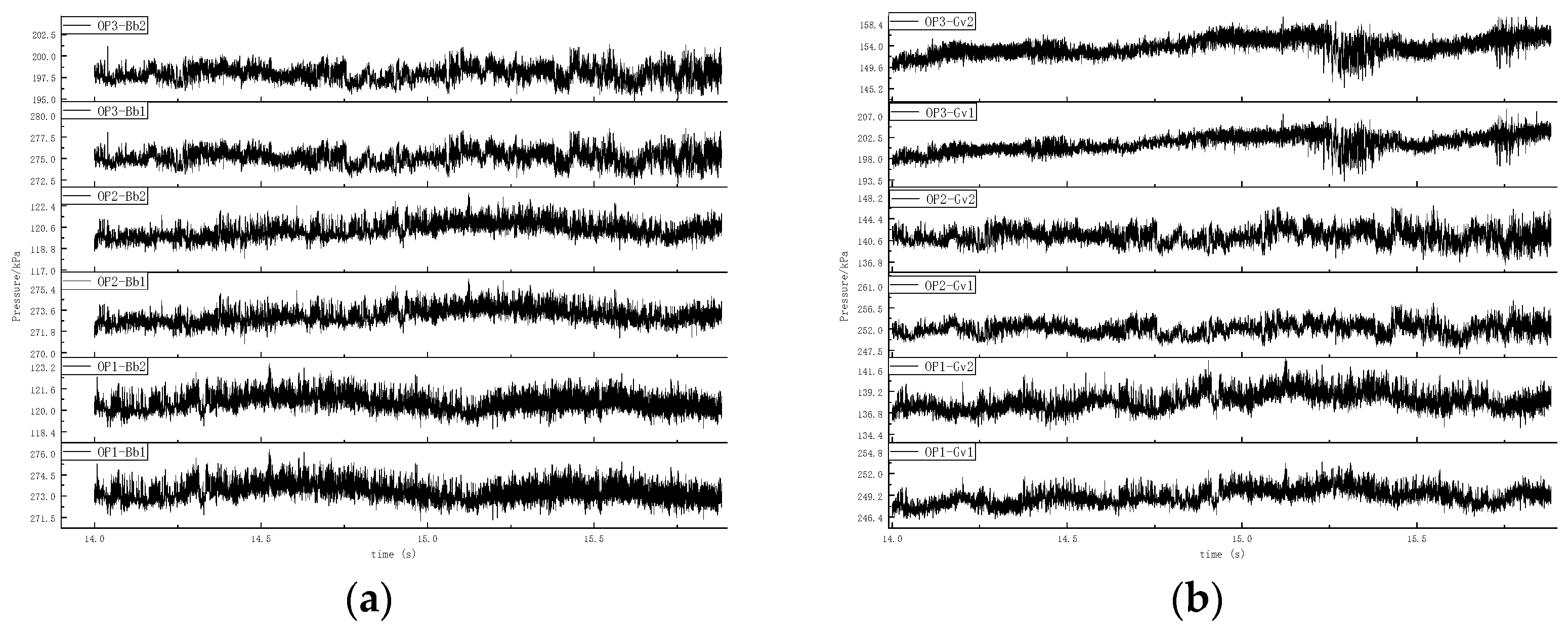
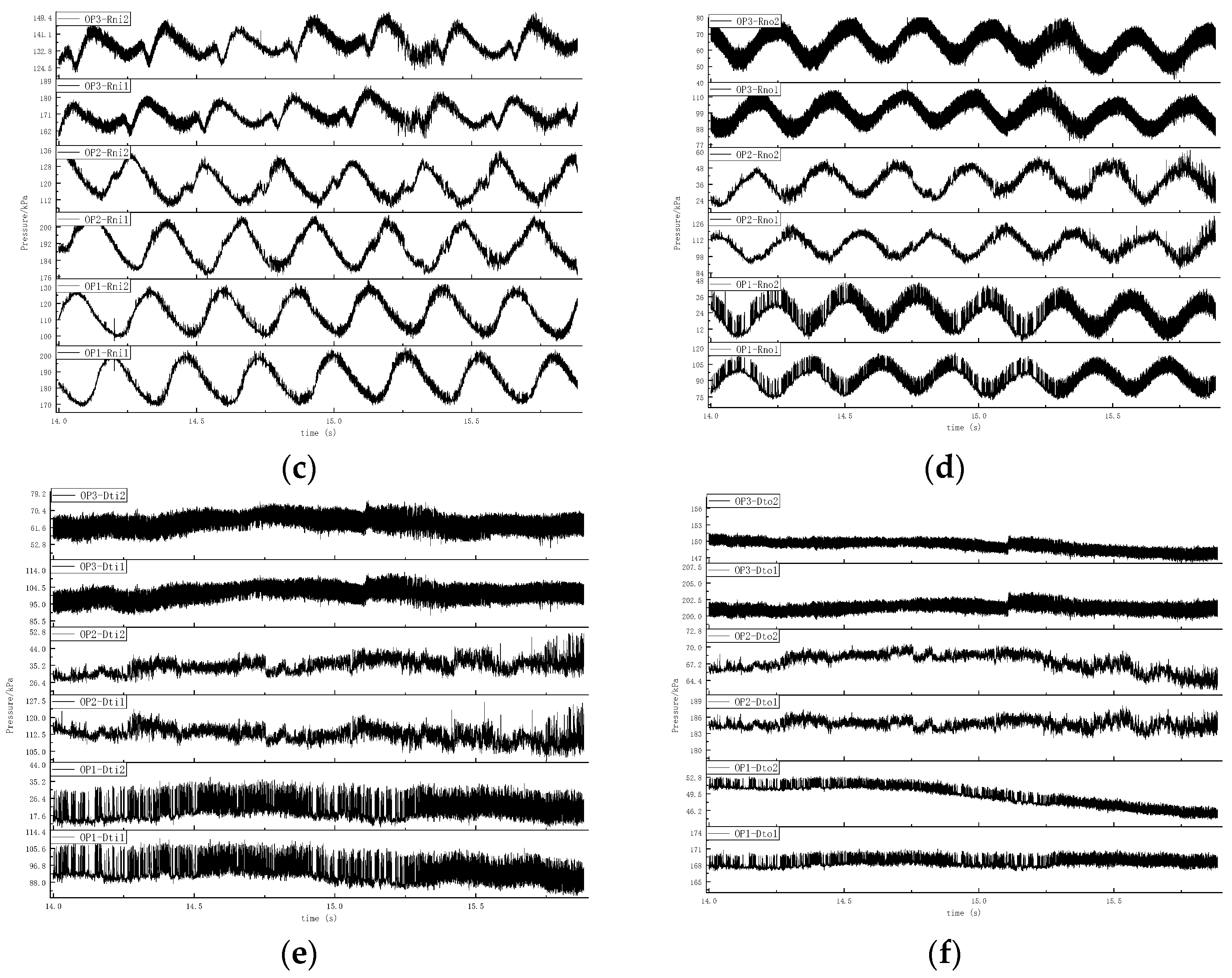
Figure 10 shows the pressure fluctuation distribution of each flow passage component of the tubular turbine under different conditions. The pressure of the turbine structural components increases with the increase in water depth due to the influence of hydrostatic pressure. The pressure at the top of the flow passage is small, whereas the pressure at the bottom of the flow passage is large. The pressure difference between the top and bottom of different flow passages is positively related to the elevation difference. Under the same conditions, the pressure fluctuation laws of the two pressure-monitoring points on the same section are the same. With the decrease in the head, the pressure fluctuation law becomes increasingly complex at the same section. Taking the runner inlet as an example, the pressure fluctuation at the runner inlet is typical sinusoidal fluctuation at the 7.7 m head of condition one. With the decrease in the water head, such as H = 6.08 in condition two and 4.6 m in condition three, a small second fluctuation period with an amplitude and period less than the main wave appears during the development from trough to peak. The lower the water head, the more obvious the period and amplitude of the secondary fluctuation. The vibration characteristics of the runner area become more complex with the decrease in the water head.
The fast Fourier transform is used to obtain the pressure fluctuation frequency spectrum characteristics at different monitoring points, as shown in Figure 11. This process is performed to further study the pressure fluctuation frequency characteristics of the turbine flow components under the influence of the free surface and water gravity. The pressure fluctuation frequency in the horizontal tubular turbine is mainly the blade passing frequency of 0.3 fn, rotating frequency fn, and blade passing frequencies of 3 fn, 6 fn, and 9 fn. The distribution of the internal spectrum characteristics of the unit is the same under different conditions. In order to clearly reflect the contribution of pressure pulsation with different frequencies to the vibration of the hydraulic turbine, the pressure pulsation amplitudes with three typical frequencies of 0.3 fn, fn and 3 fn are given in Figure 11d–f.
Low amplitude pressure pulsations of 0.3 fn and fn are the main pressure pulsations at the bulb body inlet. However, the water flow in the bulb body is relatively stable and will not have an excessive influence on the unit stability because the amplitudes are less than 5%. In the guide vane area, the pressure pulsations of 0.3 fn and fn are dominant under all conditions, and the secondary pressure pulsations of 3 fn occur. Similarly, the pressure fluctuation amplitude of 0.3 fn decreases remarkably with the decrease in the water head. In the inlet area of the runner, except for the pressure fluctuations of 0.3 fn and fn prevalent in the upstream guide vane and inlet section, the pressure fluctuation of 3 fn is the most obvious. High-frequency pressure pulsations of 6 fn and 9 fn appear at the runner inlet. At the outlet of the runner, the pressure fluctuation is mainly 3 fn. The pressure ripple at the draft tube inlet is mainly 0.3 fn, and its amplitude is remarkably larger than that of the 0.3 fn pressure ripple in other overcurrent components. The pressure fluctuation amplitude of 0.3 fn decreases obviously with the decrease in the water head. As the flow continues to flow to the draft tube outlet, the magnitude of the flow is remarkably weakened by the influence of the downstream reservoir area.
The above analysis shows that the maximum value of the 0.3 fn pressure fluctuation appears in the draft tube, and then transmits to the upstream, and the amplitude gradually attenuates. So, the low-frequency pressure pulsation of 0.3 fn in the turbine originates from the draft tube and passes through the whole unit upstream and downstream separately. The influence of the pressure pulsation decreases with the increase in the transfer distance. Pressure pulsation of frequency conversion fn occurs in the entire overcurrent component due to the rotation of the runner. With the decrease in the applied head of power plant, the deeper the submergence depth of the unit, the higher the hydrostatic pressure, the smaller the amplitude of the pressure pulsation of 0.3 fn and fn, and the weaker the influence on unit stability. The pressure fluctuation of 3 fn in the blade passing frequency is the most remarkable in the runner area and is the main cause of instability in the turbine, especially in low-head conditions. This condition is because during the operation of the horizontal tubular turbine, the blades undergo a cycle of “high pressure-low pressure-high pressure” due to the influence of hydrostatic pressure, which varies with the gradient along the water depth, on the load distribution of the blades during their rotation with the runner. This periodic pressure cycle causes the runner to bear the periodic cyclic load, which causes the runner arranged by the cantilever beam to vibrate violently, and then react to the water body, causing a coupling reaction and making the vibration at the runner more intense. Although the pressure pulsation of 3 fn decreases with the increase in the water head, and high-frequency pressure pulsations, such as 6 fn and 9 fn, are induced via water resonance in the leafless area between the runner and guide vane, these pressure pulsations of various frequencies concentrated in the runner area make the vibration in the runner area of the tubular turbine more obvious.
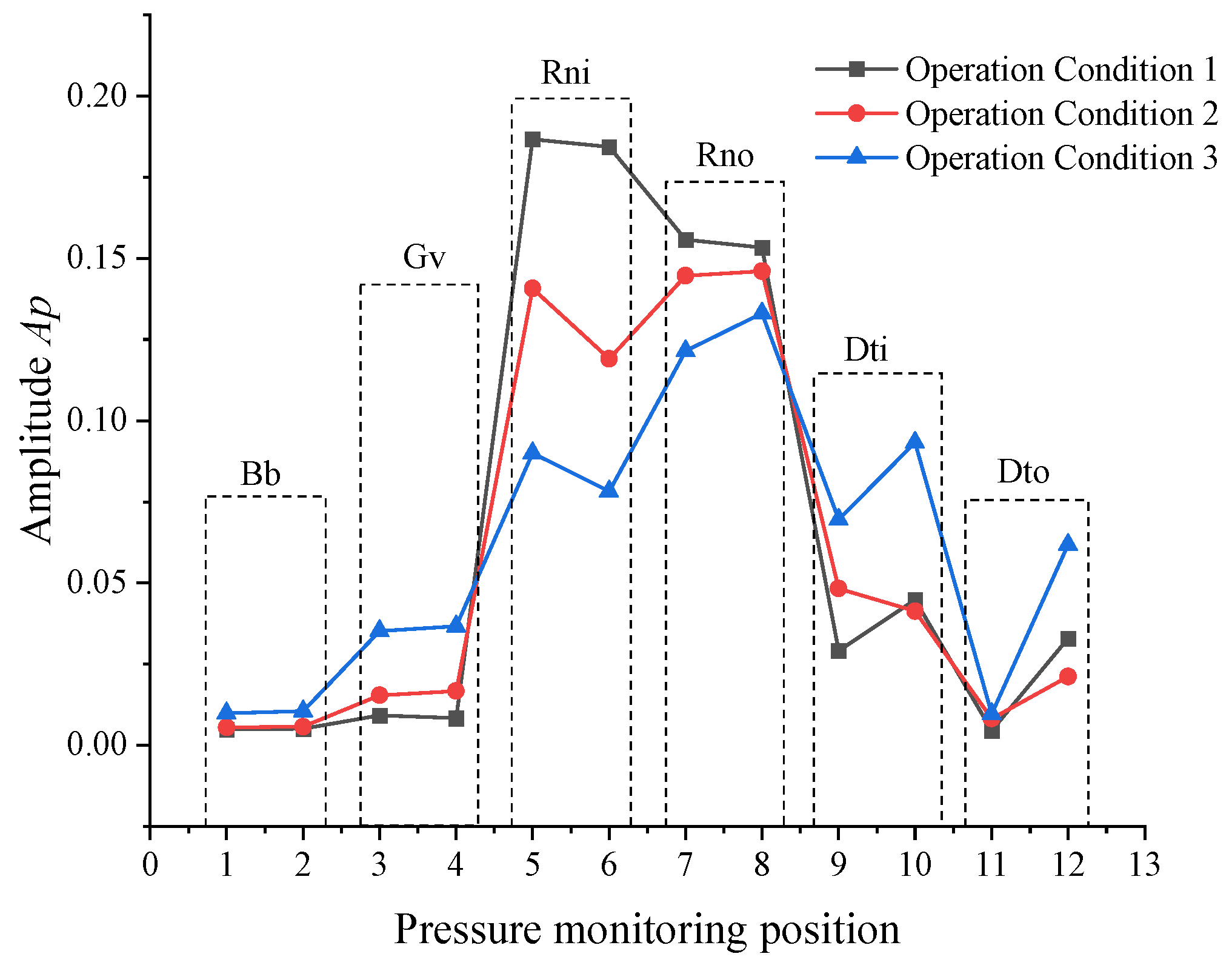
As shown in Figure 12, the maximum amplitude of pressure pulsation in each flow passage component of the turbine under different water heads is calculated to reflect the vibration characteristics of the tubular turbine more intuitively, where the maximum amplitude refers to the maximum amplitude of pressure pulsation at various frequencies measured at different monitoring points. The amplitude of pressure fluctuation in each flow-passing component of a tubular turbine varies with the change in the water head. Vibrations in the turbine are mainly concentrated in the runner and draft tube. At each head, the pressure fluctuation in the runner is the largest. The maximum vibration position in the horizontal tubular turbine is located at the runner due to the water gravity and the influence of the transverse cantilever runner structure.
4. Pressure Pulsation Analysis of Tubular Turbine Prototype
In accordance with GB/T 20043-2005 (code for site acceptance test of the hydraulic performance of hydraulic turbines, storage pumps, and pump turbines) and GB/T 17189-2017 (specification for vibration and pulsation field test of hydraulic machinery), the real machine testing of a tubular hydropower station is conducted on the basis of the existing tests and test methods in a tubular hydropower station. This process is performed to further verify the numerical research results. Considering that the pressure pulsation test within the total head range cannot be conducted during the actual measurement of the power station, the static real machine test is only performed for a tubular unit under 10%, 50%, 80%, and 100% Pr conditions and the rated head in the field test. The hydraulic parameters, such as pressure pulsation at the inlet of the hydraulic turbine unit, runner inlet, runner outlet, and draft tube outlet, are collected to obtain the vibration characteristics of each flow passage component of the turbine. The test section is shown in Figure 13. The pressure fluctuation amplitude curves at different monitoring points under the real machine operation test are shown in Figure 13b. The amplitude of pressure fluctuation in the bulb body is extremely small in the full load range. The pressure pulsation in the draft tube decreases with the increase in output, especially when the output is 10%. The pressure pulsation in the draft tube and runner is the largest, which indicates that the unit is prone to violent vibration under this condition. The pressure pulsation in the runner is the most severe under a low load (10% output), followed by the larger pressure pulsation in the runner at 80% and 100% outputs. However, the pressure ripple in the runner is lower at the 50% output. The pressure fluctuation in the runner is more intense in the high load area with large flow rate. However, the pressure fluctuation in the runner is the largest at the whole output range, which indicates that the vibration is the most intense. This conclusion is in good agreement with that of the numerical simulation.
5. Conclusions
In view of the problem of severe vibration during the operation of the tubular unit, the numerical calculation of the tubular turbine, considering the free surface and water gravity, was carried out in this paper. The flow characteristics and pressure fluctuation spectrum characteristics of the tubular turbine under different water heads are compared and analyzed, and the comparative verification was conducted between the numerical simulation results and the actual test results of the tubular power station. The results show that:
(1). Under the combined action of the hydrostatic pressure and hydrodynamic pressure, the pressure distribution inside the runner is obviously non-axisymmetric. With the reduction in the water head and the increase in the submergence depth of the hydraulic turbine, the relative pressure difference between the top and bottom of the runner chamber increases, and the runner will inevitably experience large periodic pressure fluctuations during its rotation, which will cause serious hydraulic imbalance.
(2). The water flows around the blade and forms an obvious wake vortex at the tailing edge of the blade. With the increase in the water head, the blade wake vortex moves from the hub to the middle of the flow channel and forms an obvious high-turbulent kinetic energy zone at the outlet of the runner, then the vortex flows to the draft tube with a large degree of rotation and induces a spiral vortex rope in the draft tube. When the water head is low, the impact of the water flow at the leading edge of the blade causes a high-turbulent kinetic energy zone, which leads to a more turbulent flow in the runner.
(3). Vibrations in the tubular turbine are mainly concentrated in the runner and draft tube. Low frequency pressure fluctuation caused by the draft tube vortex rope is more pronounced for the high-water head. In the full water head range, the amplitude of pressure fluctuation at the blade passing frequency is the largest in the runner, and the maximum vibration position in the tubular turbine is located at the runner due to the influence of the water gravity and transverse cantilever runner structure.
Author Contributions
Y.Z. and M.D. carried out the numerical simulations, analyzed data, Y.L. and Y.R. conducted the experiment and wrote the first draft of the manuscript. J.F. conceived and supervised the study and edited the manuscript. X.L. edited the manuscript. All authors have read and agreed to the published version of the manuscript.
Funding
This research was funded by the National Natural Science Foundation of China, grant numbers 52009105 and 52079108.
Institutional Review Board Statement
Not applicable.
Data Availability Statement
Not applicable.
Conflicts of Interest
The authors declare no conflict of interest.
References
- Huang, C.Z.; Li, J.; Yang, Z.C.; Xu, Z.W. Modal Analysis on a Runner Chamber for a Large Hydraulic Bulb Tubular Turbine. Appl. Mech. Mater. 2014, 3561, 678. [Google Scholar] [CrossRef]
- Chen, H.; Zhou, D.; Zheng, Y.; Jiang, S.; Yu, A.; Guo, Y. Transient characteristics during the co-closing guide vanes and runner blades of a bulb turbine in load rejection process. Renew. Energy 2021, 165, 2. [Google Scholar] [CrossRef]
- Shi, D. Reforms of china’s energy magagement system. China Energy 2013, 35, 6–11, (In Chinese with English Abstract). [Google Scholar]
- Wen, H. Nuclear power and hydropower development is the core of the sustainable development of the energy. China Three Gorges 2013, 24, 79–81, (In Chinese with English Abstract). [Google Scholar]
- Zhang, C.; Qi, G. Cause Analysis and Reduction of Operation Vibration of Bulb Tubular Turbine in Hengdan Hydropower Station of Baishui River. Agric. Sci.-Technol. Inf. 2015, 24, 118–119. [Google Scholar]
- Liu, X. Formation and Influence of Hydraulic Vibration in Bulb Type Tubular Turbine. Power Syst. Eng. 2006, 22, 59–60, (In Chinese with English Abstract). [Google Scholar]
- Zhong, D. Development of Bulb Tubular Unit. In Hunan Hydropower Engineering Society, Guangdong Hydropower Engineering Society, Gansu Hydropower Engineering Society. Proceedings of the Symposium on Electromechanical Technology of Hydropower Station; Gansu Hydropower Engineering Society: Lanzhou, China, 2010; 2p. [Google Scholar]
- Benišek, M.; Božić, I.; Ignjatović, B. The comparative analysis of model and prototype test results of bulb turbine. In Proceedings of the 25th IAHR Symposium on Hydraulic Machinery and Systems, Timisoara, Romania, 20–24 September 2010. [Google Scholar]
- Necker, J.; Aschenbrenner, T.; Moser, W. Cavitation in a bulb turbine. In Proceedings of the 7th International Symposium on Cavitation CAV2009, Ann Arbor, MI, USA, 16–20 August 2009. [Google Scholar]
- Li, F.; Fan, H.; Wang, Z.; Naixiang, C. Optimum design of runner blades of a tubular turbine based on vorticity dynamic. J. Tsinghua Univ. 2011, 51, 836–839. [Google Scholar]
- Duquesne, P.; Maciel, Y.; Deschênes, C. Investigation of flow separation in a diffuser of a bulb turbine. J. Fluids Eng. 2016, 138, 011102. [Google Scholar] [CrossRef]
- Li, Q.; Zhou, F.; Lin, Z.; Huang, Q.; Ma, Q.; Ren, H. Analysis of internal flow characteristics of bulb bulb tubular turbine under low flow condition. Acta Energ. Sol. Sin. 2022, 43, 465–470, (In Chinese with English Abstract). [Google Scholar]
- Sun, J.; Cai, J.; Ge, X.; Zhang, H.; Han, Y.; Wang, J.; Zhang, L.; Wu, Q.; Zheng, Y. Performance Optimization of Two-vane Bulb Tubular Turbine Based on Multi-objective Orthogonal Test. Proc. CSEE 2022, 42, 3317. [Google Scholar] [CrossRef]
- Li, Y.M.; Song, G.Q.; Yan, Y.L. Transient hydrodynamic analysis of the transition process of bulb hydraulic turbine. Adv. Eng. Softw. 2015, 90, 152–158. [Google Scholar] [CrossRef]
- Zheng, Y.; Jiang, W.; Chen, Y.; Sun, A. Study on Low frequency pulsation of Tubular Turbine and Characteristics of Tailpipe Vortex Zone. Trans. Chin. Soc. Agric. Mach. 2018, 49, 165–171. [Google Scholar]
- Vu Viet, L.; Chen, Z.; Choi, Y.-D. Study on swirl flow in a draft tube of a bulb hydro turbine model. J. Adv. Mar. Eng. Technol. 2018, 42, 812–817. [Google Scholar]
- Zhen Canxin extract translation. Size effect of bulb turbine. Water Power 1991, 4, 61–63.
- Liu, Y.; Chang, J. Influence of gravity on flow field analysis and hydraulic performance evaluation of bulb turbine. J. Hydraul. Eng. 2008, 39, 96–102, (In Chinese with English Abstract). [Google Scholar]
- Feng, J.; Zhu, G.; Wang, Z.; Wu, G.; Luo, X. Effect of second-order Stokes nonlinear tidal wave on performance of tidal tubular turbines. Trans. Chin. Soc. 2019, 35, 48–54, (In Chinese with English Abstract). [Google Scholar]
- Xu, H.; He, C.; Meng, L.; Zhang, Y. Effect of clearance cavitation on pressure pulsation characteristics of bulb turbine. J. Hydroelectr. Eng. 2021, 40, 96–102. [Google Scholar]
- Zhao, Y.; Li, Z.; Liao, W.; Luo, X. Numerical investigation of free surface effect on performance of bulb turbine. J. Hydroelectr. Eng. 2018, 37, 8–14, (In Chinese with English Abstract). [Google Scholar]
- Zhao, Y.; Dang, M.; Feng, J.; Luo, X.; Li, Z. Effects of free surface and water gravity on the stress-strain of tubular turbine blades. Trans. Chin. Soc. Agric. Eng. 2022, 38, 52–60, (In Chinese with English Abstract). [Google Scholar]
- Zhao, Y.; Feng, J.; Li, Z.; Dang, M.; Luo, X. Analysis of Pressure Fluctuation of Tubular Turbine under Different Application Heads. Sustainability 2022, 14, 5133. [Google Scholar] [CrossRef]
- Tao, W. Numerical Heat Transfer; Xi’an Jiaotong University Press: Xi’an, China, 2001. [Google Scholar]
- Li, R.; Tan, H.; Li, Q.; Han, W.; Jiang, L. Research on Pressure Fluctuation of Low head pump Turbine under Turbine Condition. J. Hydroelectr. Power 2015, 34, 85–90. [Google Scholar]
Figure 1.
Watershed geometric model: (a) Computational domain; (b) Schematic of the turbine.

Figure 2.
Grid independence verification.

Figure 3.
Calculation of catchment grid: (a) Global domain grid; (b) bulb body; (c) guide vane; (d) runner; (e) draft tube.
Figure 3.
Calculation of catchment grid: (a) Global domain grid; (b) bulb body; (c) guide vane; (d) runner; (e) draft tube.

Figure 4.
Model test verification: (a) Simplified model and measuring point layout; (b) comparison between numerical simulation and experiment.
Figure 4.
Model test verification: (a) Simplified model and measuring point layout; (b) comparison between numerical simulation and experiment.

Figure 5.
Water head diagram of horizontal tubular turbine.

Figure 6.
Pressure distribution on the middle section of the runner: (a) Operation condition 1; (b) operation condition 2; (c) operation condition 3.
Figure 6.
Pressure distribution on the middle section of the runner: (a) Operation condition 1; (b) operation condition 2; (c) operation condition 3.

Figure 7.
Turbulent kinetic energy of the runner: (a) Operation condition 1; (b) operation condition 2; (c) operation condition 3.
Figure 7.
Turbulent kinetic energy of the runner: (a) Operation condition 1; (b) operation condition 2; (c) operation condition 3.

Figure 8.
Vortex distribution in tubular turbines: (a) Operation condition 1; (b) operation condition 2; (c) operation condition 3.
Figure 8.
Vortex distribution in tubular turbines: (a) Operation condition 1; (b) operation condition 2; (c) operation condition 3.

Figure 9.
Schematic of important sections and monitoring points.

Figure 10.
Pressure fluctuation distribution under different conditions: (a) Bulb type; (b) guide vane; (c) runner inlet; (d) runner outlet; (e) draft tube inlet; (f) draft tube outlet.
Figure 10.
Pressure fluctuation distribution under different conditions: (a) Bulb type; (b) guide vane; (c) runner inlet; (d) runner outlet; (e) draft tube inlet; (f) draft tube outlet.


Figure 11.
Pressure spectrum of different monitoring points under different conditions: (a) Operation condition 1; (b) operation condition 2; (c) operation condition 3; (d) 0.3 fn; (e) fn; (f) 3 fn.
Figure 11.
Pressure spectrum of different monitoring points under different conditions: (a) Operation condition 1; (b) operation condition 2; (c) operation condition 3; (d) 0.3 fn; (e) fn; (f) 3 fn.

Figure 12.
Pressure pulsation amplitude curves at different monitoring points under different conditions.
Figure 12.
Pressure pulsation amplitude curves at different monitoring points under different conditions.

Figure 13.
Pressure pulsation of tubular turbine prototype. (a) Arrangement of measuring points for real machine pressure pulsation; (b) test pressure fluctuation amplitude curves at different monitoring points under different outputs.
Figure 13.
Pressure pulsation of tubular turbine prototype. (a) Arrangement of measuring points for real machine pressure pulsation; (b) test pressure fluctuation amplitude curves at different monitoring points under different outputs.


Table 1.
Specific parameters at different working conditions.
| Condition | Working Head | Flow (m3/s) | Guide Vane Opening (°) | Blade Angle (°) |
|---|---|---|---|---|
| 1 | 7.7 m | 315.3123 | 62 | 5.2 |
| 2 | 6.08 m | 303.2468 | 66 | 5.2 |
| 3 | 4.67 m | 300.1159 | 70 | 5.2 |
Disclaimer/Publisher’s Note: The statements, opinions and data contained in all publications are solely those of the individual author(s) and contributor(s) and not of MDPI and/or the editor(s). MDPI and/or the editor(s) disclaim responsibility for any injury to people or property resulting from any ideas, methods, instructions or products referred to in the content. |
© 2023 by the authors. Licensee MDPI, Basel, Switzerland. This article is an open access article distributed under the terms and conditions of the Creative Commons Attribution (CC BY) license (https://creativecommons.org/licenses/by/4.0/).
Share and Cite
MDPI and ACS Style
Zhao, Y.; Li, Y.; Feng, J.; Dang, M.; Ren, Y.; Luo, X. Vibration Characteristics of a Tubular Turbine Prototype at Different Heads with Considering Free Surface and Water Gravity. Water 2023, 15, 791. https://doi.org/10.3390/w15040791
AMA Style
Zhao Y, Li Y, Feng J, Dang M, Ren Y, Luo X. Vibration Characteristics of a Tubular Turbine Prototype at Different Heads with Considering Free Surface and Water Gravity. Water. 2023; 15(4):791. https://doi.org/10.3390/w15040791
Chicago/Turabian StyleZhao, Yaping, Yanrong Li, Jianjun Feng, Mengfan Dang, Yajing Ren, and Xingqi Luo. 2023. "Vibration Characteristics of a Tubular Turbine Prototype at Different Heads with Considering Free Surface and Water Gravity" Water 15, no. 4: 791. https://doi.org/10.3390/w15040791
Note that from the first issue of 2016, this journal uses article numbers instead of page numbers. See further details here.