
Failure Characteristics of the Water-Resisting Coal Pillar under Stress-Seepage Coupling and Determination of Reasonable Coal Pillar Width
1
Kekegai Coal Mine Shaanxi Yanchang Petr Yulin Coal Chem Co., Yulin 719000, China
2
School of Mines, China University of Mining and Technology, Xuzhou 221116, China
3
MOE Key Laboratory of Deep Coal Resource Mining, China University of Mining and Technology, Xuzhou 221116, China
*
Author to whom correspondence should be addressed.
Water 2023, 15(5), 1002; https://doi.org/10.3390/w15051002
Submission received: 9 February 2023
/
Revised: 26 February 2023
/
Accepted: 27 February 2023
/
Published: 6 March 2023
/
Corrected: 9 May 2023
(This article belongs to the Special Issue Risk Management Technologies for Deep Excavations in Water-Rich Areas)
Abstract
:Groundwater inrush hazard has always been a great threat to the construction of vertical shafts in coal mines. Generally, the failure of the water-resisting coal pillar under coupled stress-seepage conditions around the vertical shaft is the main reason for the generation of the water inrush channel. In order to understand the mechanical behaviors of the water-resisting coal pillar, the strength of typical coal affected by the size and water content was investigated, and the stress sensitivity of permeability was investigated by a stress-seepage coupling test. The stress field and deformation of the water-resisting coal pillar were investigated by numerical simulation, the stability of the water-resisting coal pillars with different widths was evaluated, and the reasonable width of the coal pillars under coupled stress-seepage condition was determined. Results show that the water content and coal pillar width have a great influence on the mechanical characteristics of coal samples. Under the conditions of lower water content and larger coal sample width, the coal sample presents higher strength, smaller axial deformation, smaller permeability and porosity, and weak sensitivity to stress. The simulation results show that the boundary of the main roadway at the end of the coal pillar is dominated by tensile stress, and fractures can significantly contribute to the destruction of coal pillars. With the increase in the width of the water-resisting coal pillar, the internal damage variable, maximum tensile stress, porosity, and average water flow velocity of the coal pillar decrease, which reduces the risk of water inrush and improves the safety of the water-resisting coal pillar. An evaluation model of the reasonable width of the water-resisting coal pillar under the stress-seepage coupling was proposed, and the model was verified by the shear slip law and experimental results. This study provides theoretical and experimental guidance for the risk management of groundwater inrush disaster during the construction of vertical shafts in coal mines.
1. Introduction
The complex hydrogeological conditions of mines have seriously affected the safe production activities of mines in recent years, and the prevention and control of water inrush in mines has received wide attention [1,2]. To realize the rapid recovery of mining economic costs, the shaft construction period should be reduced as far as possible. Conventional shaft construction methods include the freezing method, drilling method, grouting method, and open caisson method. The air reverse circulation drilling method has the advantages of high efficiency, energy conservation, environmental protection, and a wide application range [3]. However, high-pressure mud will be produced during this shaft construction method, which is prone to induce water inrush accidents. Therefore, the application of the air reverse circulation drilling method in the complex geological environment is limited. To prevent water inrush in the process of air reverse circulation drilling, it is necessary to study the evolution law of hydraulic characteristics of the coal pillar under complex hydrogeological conditions in this drilling process.
A large number of studies on the prevention and control of water inrush under complex geological conditions have been conducted. Zhang et al. [4] proposed that formation pressure, aquifer water pressure, mining scale, and geological structure are the main factors controlling water inrush. Ma et al. [5,6] reviewed the water-inrush seepage mechanism from three aspects: stress-seepage coupling mechanism, flow transition mechanism and rock erosion mechanism. The evolution law of stress field and seepage field during water inrush is fully studied by numerical method and experimental analysis. Ganji et al. [7] evaluated the structural stability and safety of heterogeneous rock dam under loads such as dead weight and hydrostatic pressure using overstress and sliding safety indexes. Guo et al. [8] analyzed the water inrush mechanism qualitatively and quantitatively. Through acoustic emission (AE) technology and scanning electron microscope (SEM), Chen et al. [9] analyzed the mechanical and micro-fracture behavior of water-bearing coal samples. It was concluded that the coal pillar should be prevented from being subjected to inclined load and water erosion to avoid water inrush accidents. Hosseinzadeh et al. [10] proposed that seepage flow is a type of load widely distributed in the bedrock, which has an important effect on the water inrush of the dam. Chen et al. [11] believed that retaining a water-resisting coal pillar is an effective measure to prevent water inrush, and water pressure and seepage rate of overlying strata are key factors to predict potential water inrush. Ma et al. [12] drew the stress distribution of the floor under different coal pillar widths and derived the stress distribution data of the floor. Numerical simulation method is used to compare the stress distribution of roadway floor and the deformation characteristics of surrounding rock under different coal pillar widths. Finally, they determine the width and optimize the size of the coal pillar. Hu et al. [13] summarized that retaining a water-resisting coal pillar is the most effective water-saving method for coal seam mining, and proposed the conditions for determining the critical width of the water-resisting coal pillar. Ma et al. [14] proposed that when mining roadway excavation encountered fault fracture zone, permeability and porosity increased with time, and the granular structure of broken surrounding rock was easy to form water channel, which may cause water gusher hazard. The above research shows that retaining a water-resisting pillar is the most convenient and economic measure to prevent water inrush from coal seams.
The width of the water-resisting coal pillar is an important parameter of the coal pillar. It is very important to determine a reasonable width of coal pillar to ensure mine safety and save coal resources. Chen et al. [15] obtained the empirical formula and the safe width of the coal pillar in the section based on simulation analysis and mathematical measurement. Wang et al. [16] derived the evaluation formula of the width of the protective coal pillar and analyzed the failure form of the main roof. It is concluded that the breaking position of the main roof has a great influence on the width of the protective coal pillar. The critical width of the protective coal pillar in coal seam stope is determined to ensure the stability of the surrounding rock. Chen et al. [11] proposed that it is necessary to understand the influence of water seepage and loading rate on the mechanical properties of coal rock samples and the development of fracture network, so as to determine the width of the water-resisting coal pillar. Jaiswal et al. [17] conducted field monitoring and numerical simulation for the whole process of coal mass strain softening during coal pillar mining. The monitoring results show that the yield of coal pillar begins almost 2/3 of the peak strength. On this basis, the statistical expressions of the pillar strength and the estimation after failure are obtained, and the reasonable width range of the pillar is given. Dong et al. [18] established the mechanical model of the main roof rock beam, deduced the limit span and limit deflection of the rock beam fracture, and verified the reliability of the thickness of the water-resisting coal pillar. Through theoretical analysis and simulation analysis, Hu et al. [13] provided a theoretical basis for the rationality of the width of the water-resisting coal pillar. It was reported that the maximum width of the water-resisting coal pillar is the critical width, and the coal pillar was divided as mine pressure affected zone, effective waterproof zone, and water level affected zone with respect of water resistance. Das et al. [19] concluded that there is no suitable calculation formula to estimate the strength of inclined coal pillars considering many factors at present. The strength of inclined coal pillars with different widths is estimated by numerical simulation. Based on the hydraulic model of floor water inrush, Shi et al. [20] put forward the calculation formula of the fault water-resisting coal pillar in the stope considering the influencing factors such as confined water pressure and coal seam dip angle. Li et al. [21] determined the safe width of the water-resisting coal pillar in combination with the mechanical expression of the confined water pressure and the width of the water-resisting coal pillar under the limit equilibrium state. Wang et al. [22] classified the structure of the water-resisting coal pillar into the plastic zone affected by rock pressure, the core zone with effective waterproof and the water pressure damage zone, and measured the physical shape distribution of the water-resisting coal pillar using ultrasonic detection technology. This study provides a theoretical basis for determining the width of the water-resisting coal pillar. Wang et al. [23] determined the safe width of the water-resisting coal pillar by combining the physical model test results with the elastic-plastic limit equilibrium theory, and concluded that the coal seam before mining can be divided into fault-affected zone, elastic zone, and plastic yield fracture zone according to the stress and displacement characteristics. Based on field experience and numerical model studies, Mathey et al. [24] proposed another South African squat coal pillar strength formula. Combined with numerical simulation research, Yao et al. [25] monitored coal samples with different water contents and strain rates through a non-destructive immersion test, which is significant for the design of the water-resisting coal pillar.
The above research has deeply explored the determination method of coal pillar width. However, the evolution law of the stress-seepage coupling characteristics of water inrush from rocks under the action of the high-confined water has not been considered. Bukowski [26] analyzed the water inrush event in Poland, and comprehensively analyzed the wellbore water disaster in combination with influencing factors (such as the intensity of water inrush, and the content of suspended substances in the water flowing into the wellbore). Ma et al. [27] obtained the temporal and spatial distribution of hydraulic characteristics through numerical simulation. The rock particles near the fluid outlet first fluidized and continuously migrated outward, resulting in the increase of the porosity and permeability of fault rock. Through establishing the hydrogeological model of water inrush, Huo et al. [28] analyzed the relationship between hydraulic gradient, water inrush and relevant factors, and summarized the general law of water inrush disasters in aquifers. Kerimov et al. [29] developed a numerical work flow to study the effect of non-frictional, convex and particle size polydispersity on the stress-seepage coupling of porosity, permeability, and elastic bulk modulus in granular porous media. Ma et al. [30] used the coupling equation of stress and seepage to model the seepage law. It was concluded that under the support pressure and unloading of the coal mining face, the dense seepage pathways can be formed by the fracture connection, thus causing groundwater inrush. Chen et al. [31] proposed that the evolution of fracture in rock mass causes the mining-induced fracture to evolve along the direction of principal stress and connect with each other, resulting in the formation of water inrush pathways. Liang et al. [32] analyzed the change rule of stress, displacement and water pressure during tunnel excavation, providing corresponding observation indicators for the water inrush process. Ma et al. [33] proposed that in the process of water inrush, the nonlinear characteristics of rocks are gradually changed due to the erosion of flowing water, and the particle loss is the main reason for the decline of nonlinear hydraulic characteristics. Li et al. [34] proposed that the lower the compressive stress level, the stronger the compressibility of broken rock mass, the stronger the stress sensitivity of small granular broken gangue, and the more likely the water inrush accident occurs. Yin et al. [35] put forward that mining activities disturb the original stress state, which leads to redistribution of stress, rock failure, and the formation of a water-conducting failure zone around the mining panel. Ma et al. [36,37] proposed the uniaxial compressive strength and elastic modulus of coal samples gradually deteriorate during the dry-wet cycle. According to the cyclic failure of the samples caused by wet and dry cycles, the deterioration process of the mechanical properties of the samples was divided into initial deterioration stage and re-deterioration stage, which verified the periodic failure of the cemented structure. Behrenbruch et al. [38] introduced a model to classify the characteristics of geological sedimentary environments and associated pore structures. In “reverse modeling” applications, pore structure parameters, porosity, and permeability are estimated for specific geological conditions. High confined water pressure is an important factor in mine water inrush, and also the basic power of coal seam water inrush [39]. Wu et al. [40,41] elaborated the influence mechanism of aggregate size distribution on rock sample and analyzed the contribution of aggregate size distribution to the seepage performance of rock sample. When the typical fractured coal body is subject to high seepage pressure, water inrush disasters are more likely to occur. However, the above research mainly focuses on the seepage and mechanical characteristics of brittle rock materials such as sandstone and granite, and less attention is paid to the seepage mechanical characteristics of coal rock.
In fact, the mechanical properties of coal rock are different from the above rock materials. In particular, the mechanical properties of coal rock will be changed greatly after it has been softened by water. Therefore, the stress-seepage coupling characteristics of coal rock are extremely complex, and an effective method to evaluate the stability of the water-resisting coal pillar is urgently required. In addition, the calculation results of the current calculation criteria for the width of the water-resisting coal pillar are conservative and have a large deviation from the actual results, resulting in a waste of coal resources. To analyze the stress-seepage coupling characteristics of the water-resisting coal pillar, the stress-seepage coupling tests of coal samples with different water contents and inner diameters were carried out, and the stress-seepage coupling characteristics of coal samples were obtained in this study. Then, the numerical simulation of water inrush in the shaft under different conditions was carried out, and the spatial distribution characteristics of stress and deformation of the water-resisting coal pillar were obtained. Finally, the simulation results of water inrush from water-resisting coal pillar with different widths were discussed, the evolution laws of the damage variable, maximum tensile stress, porosity, and average velocity of the coal pillar were obtained, and the calculation method of reasonable reserved width of the water-resisting coal pillar under compressed air reverse circulation drilling method was proposed. This study provides a theoretical and experimental reference for the prevention and control of coal seam water inrush.
2. Engineering Background
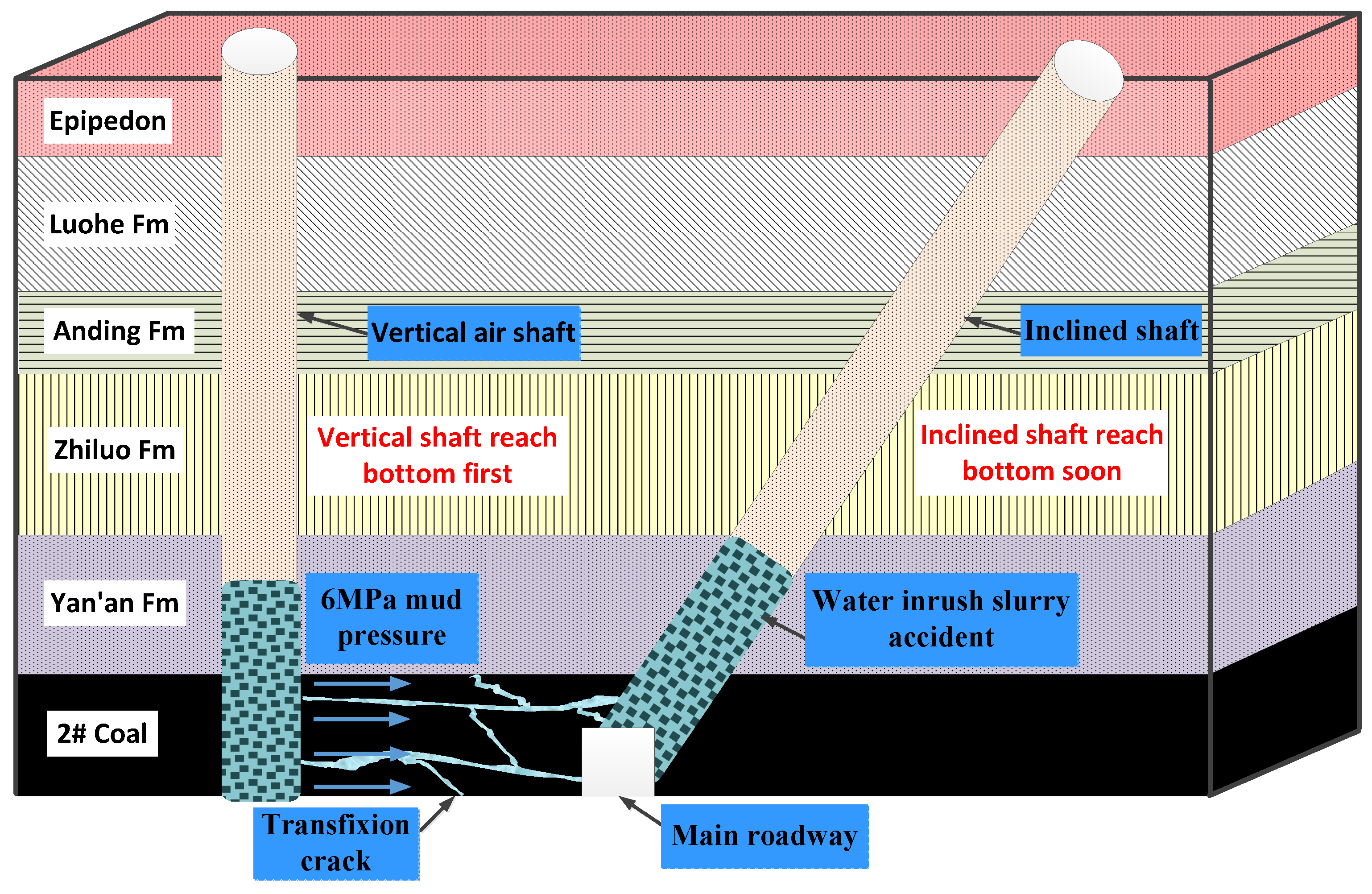
Kekegai Coal Mine is located in Yuyang District, Yulin City, Shaanxi Province. In this coal mine, the compressed air reverse circulation drilling method is innovatively adopted, which effectively improves the excavation speed of the shaft. However, in this method, mud at the depth of the wellbore will form high pore pressure, exposing the coal around the deep wall to high water pressure. As shown in Figure 1, during the shaft excavation, the internal fractures of the coal and rock mass around the shaft continue to expand and the permeability increases significantly under the influence of mining stress and high water pressure. As a result, the mud will enter the inclined shaft through the seam fractures.
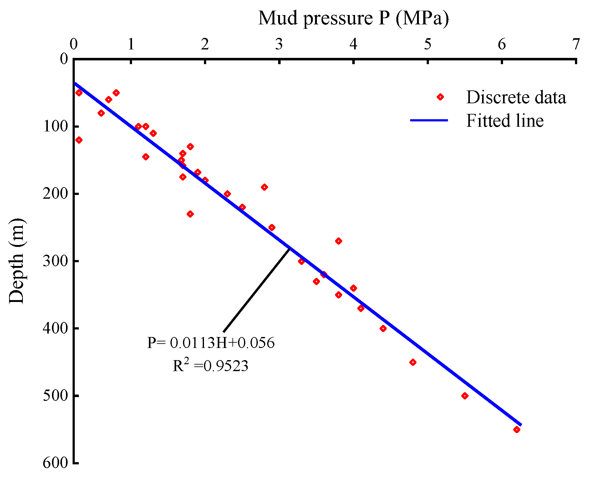
To explore the change rule of mud pressure with the shaft driving depth, the relationship curve between mud pressure and shaft depth is drawn in combination with the data of Kekegai Coal Mine, as shown in Figure 2.
During the excavation of the air inlet and return shaft in Kekegai Coal Mine, the mud pressure P shows a linear increasing trend with the increase in the well depth. Through field measurement, the linear fitting equation of mud pressure under different well depths is P = 0.0113H + 0.056, and the fitting goodness R2 is 0.9523. The coefficient of the first order term reflects the variation in mud pressure with the well depth. The constant term reflects the formation properties of the well.
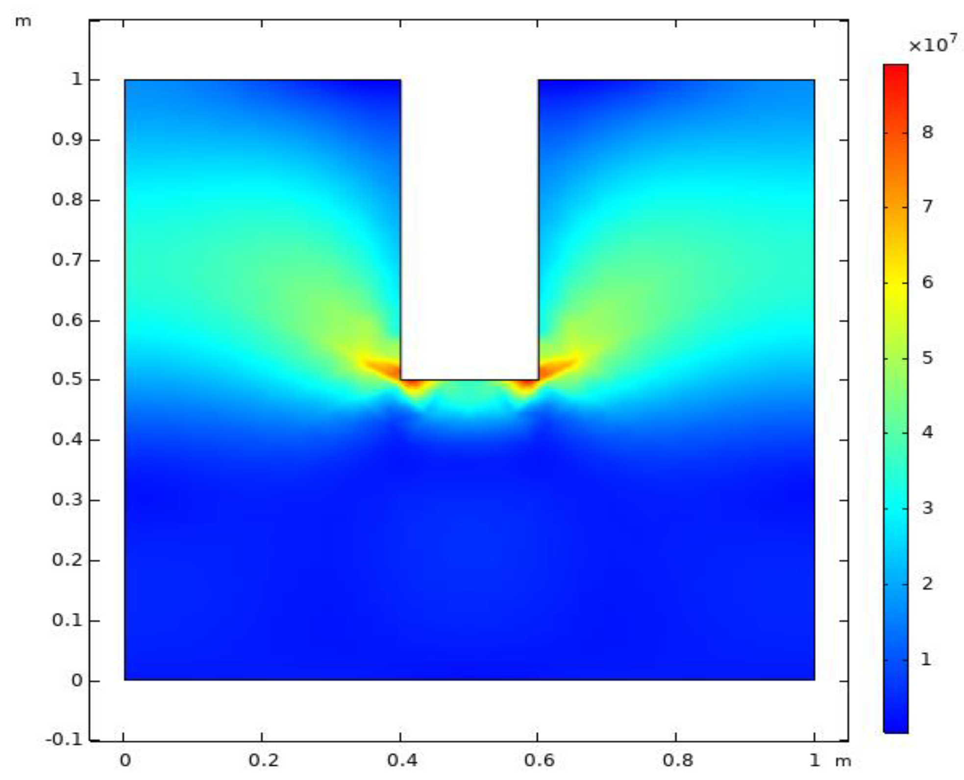
As shown in Figure 3, with the continuous increase in the excavation depth in shaft, the stress of rock mass around the shaft wall and at the outer edge keeps rising. In particular, the stress concentration is greatest at the outer edge of the shaft bottom. At the same time, the mud pressure used in the shaft excavation also has a certain loading effect on the shaft wall. Under the joint action of stress and mud pressure, a complex fracture network is formed in the surrounding rock of the shaft, leading to the fracture evolution of the rock mass.
3. Stress-Seepage Coupling Test on Coal Rock
3.1. Selection and Preparation of Coal Samples
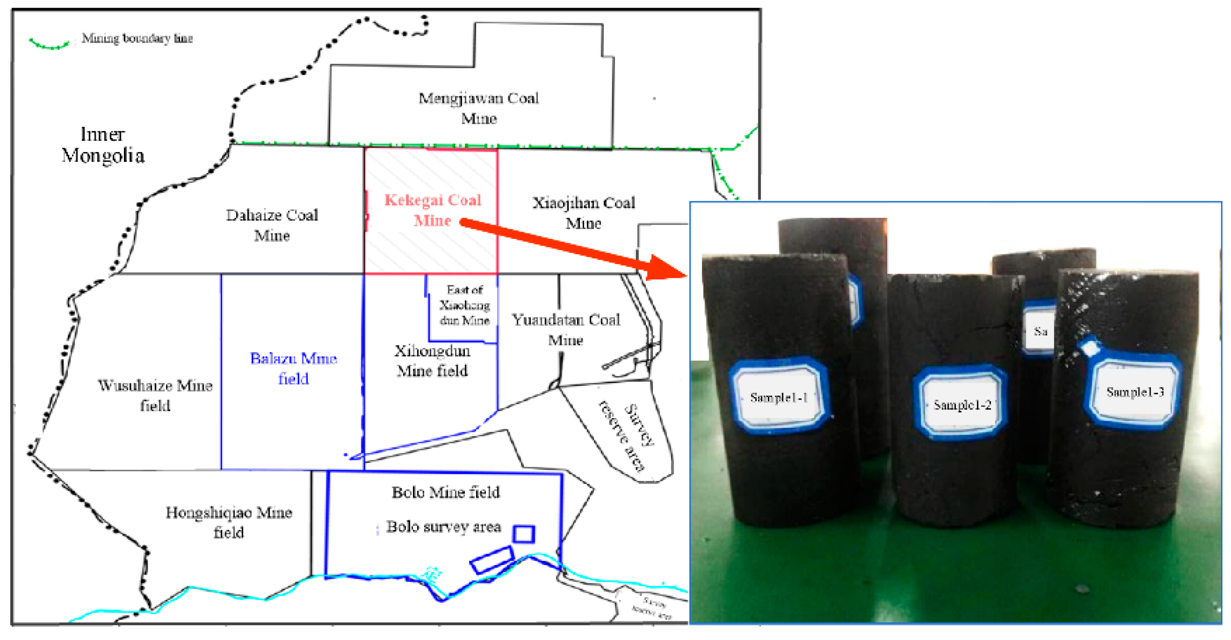
The coal rock sample was taken from the surrounding rock around the shaft of Coal Seam 2 in Kekegai Coal Mine, Yulin City, Shaanxi Province (see Figure 4). The coal rock density was 1.5 kg/m3, and the saturated water content was 14%. To explore the mechanical and seepage evolution characteristics of the coal pillar, hollow cylinder coal samples were made, as shown in Figure 5. The sample was processed into a coal core with a diameter of 70 mm and a length of 140 mm by the drilling sampler and rock cutter. Coal samples were put into the air circulation oven to dry for 12 h, and then the natural immersion method was used to obtain coal samples with different moisture contents.
3.2. Experimental Methods, Apparatus and Scheme
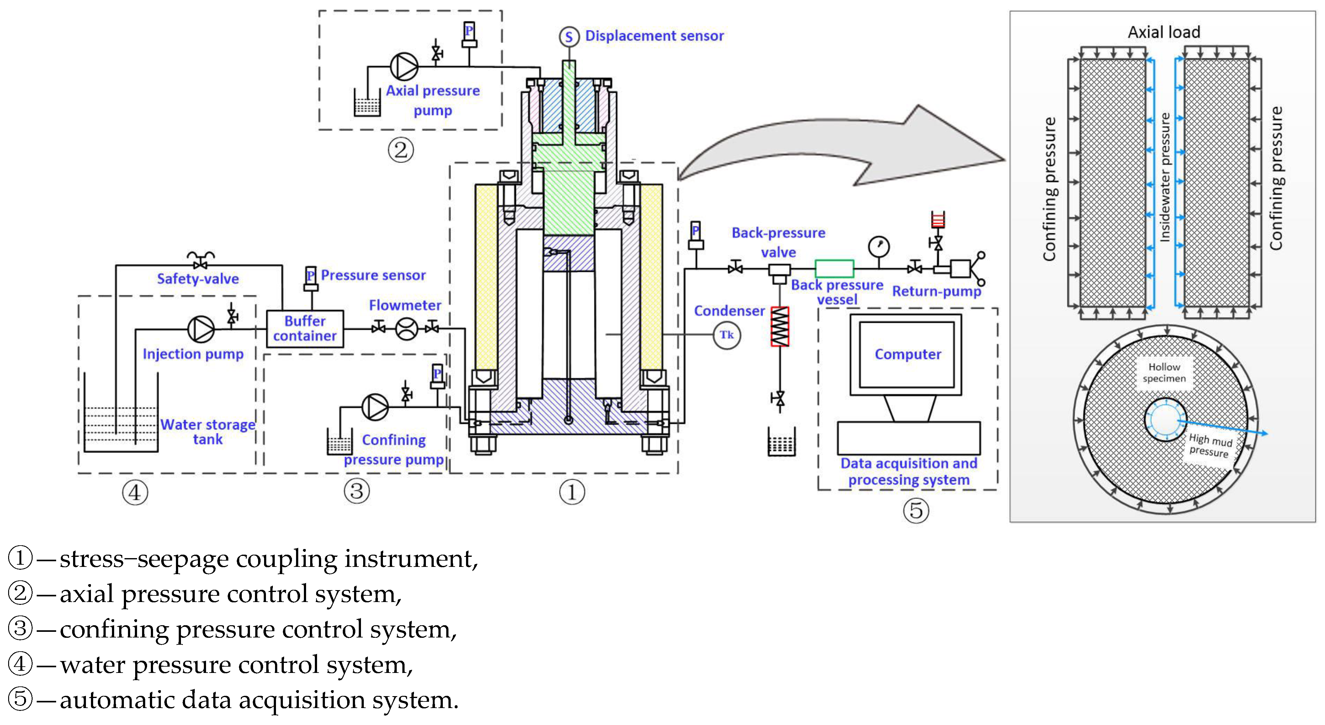
To obtain the evolution law of the stress-seepage mechanical characteristics of coal rock under the action of high-pressure mud inside the shaft, the stress-seepage coupling test method for the surrounding rock of the shaft was proposed, and the stress-seepage coupling environment of the surrounding rock of the deep shaft was restored. As shown in Figure 5, axial pressure and confining pressure were applied to the hollow cylindrical coal sample, and water pressure was applied to the inner wall of the coal sample, so that the radial seepage of water was realized in the sample.
To achieve the above test methods, a thermal-hydraulic-mechanical (THM) triaxial coupling test system was independently developed, as shown in Figure 5. At the beginning of the test, the sample was placed in the stress-seepage coupling instrument, and the axial pressure and confining pressure control systems simultaneously imposed loads on the sample. The water pressure control system provided different water pressures to the inner wall of the coal sample. The automatic data acquisition system was used to monitor the seepage and mechanical characteristics of coal samples in real time.
Table 1 shows the experimental scheme of the sample. The inner diameter and water content of coal samples were taken as variables, and the change rule of seepage mechanical characteristics of different coal samples under the water pressure of 6 MPa and axial load of 10 MPa was studied. The inner diameter dimensions were classified into five groups of 15 mm, 20 mm, 25 mm, 30 mm and 35 mm, corresponding to tests A, B, C, D, and E. For each group of tests, samples with three different water content (0%, 6.28%, and 13.65%) were designed.
3.3. Experimental Results
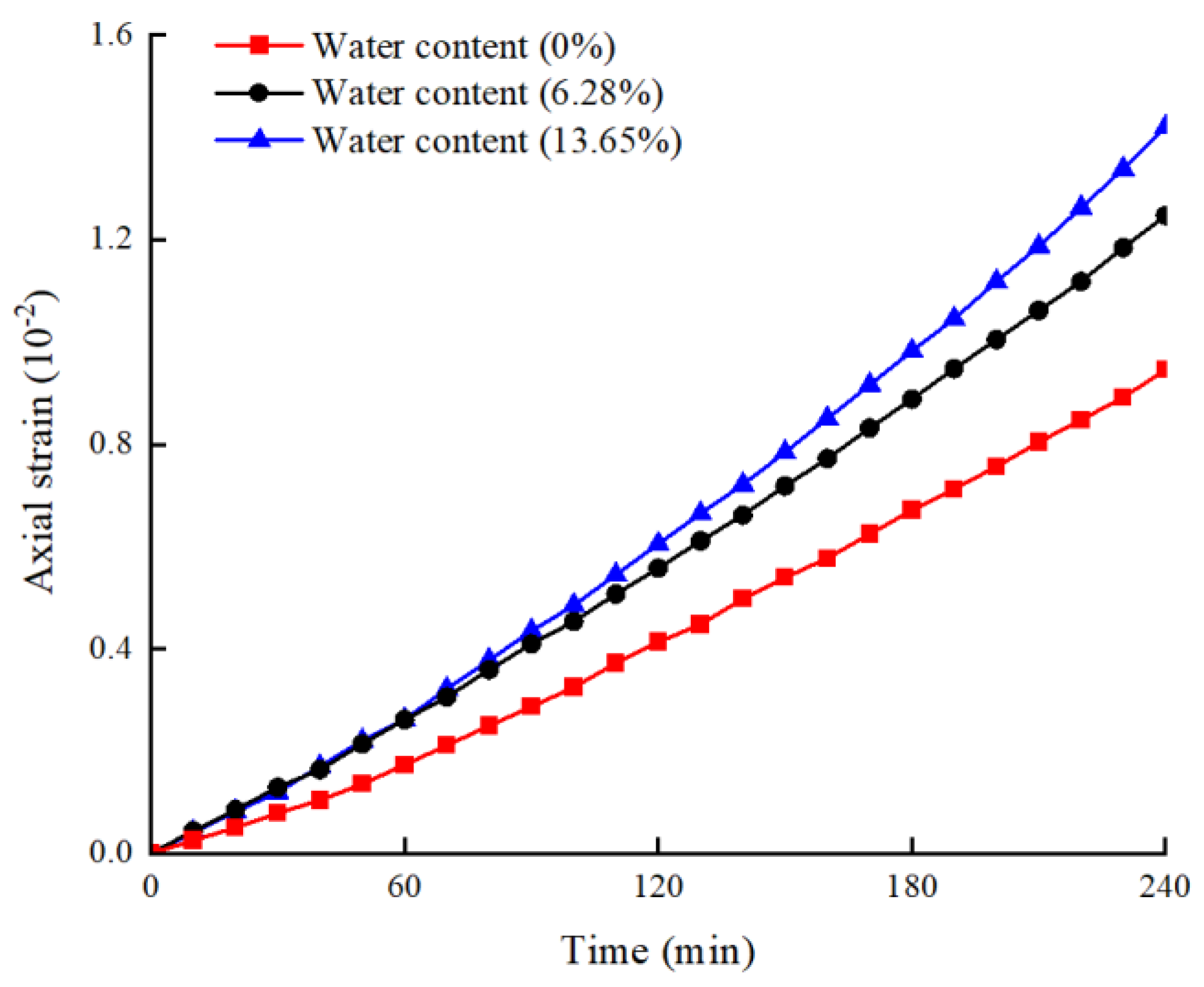
Figure 6 shows the axial strain evolution curve of coal samples with different water contents under the stress-seepage coupling (taking samples in Group C as an example). The three curves successively experience the initial deformation stage, stable deformation stage, and accelerated deformation stage. Comparing the three curves, it can be found that with the increase in water content, the axial strain of the sample increases faster, and the accelerated deformation stage is reached earlier. This shows that with the increase in water content, the lower the internal structural strength of the coal sample, the greater the deformation of the coal sample under the stress-seepage coupling, and the shorter time required for the structural failure.
Figure 7a shows the change rule of the average flow velocity of coal samples with different water contents under the stress-seepage coupling (taking samples in Group C as an example). With the increase in time, the average flow rate inside the coal sample increases continuously. At the initial stage of the test, the lower the water content of the coal sample, the greater the average flow rate. However, with the increase in seepage time, the average flow velocity in the sample with high water content gradually exceeds that in the sample with low water content. In the sample with large water content, the increase in flow rate is greater, and the main increase in flow rate occurs after 120 min. This is because the structural strength of the sample with higher water content is lower. Under the stress-seepage coupling effect, the fracture expands quickly. As a result, the average velocity increases rapidly in the middle and late periods and finally exceeds the coal samples with a low water content. Figure 7b shows the relationship between porosity and water content of coal samples under the stress-seepage coupling. It is observed that the coal sample with higher water content has a more significant porosity growth, which indicates that the cracks in the coal sample have a more significant expansion under the stress-seepage coupling effect. After 180 min, the porosity of coal samples with different water contents begins to decrease. This is due to the continuous compaction of coal samples under the loading, and the pores are gradually closed.
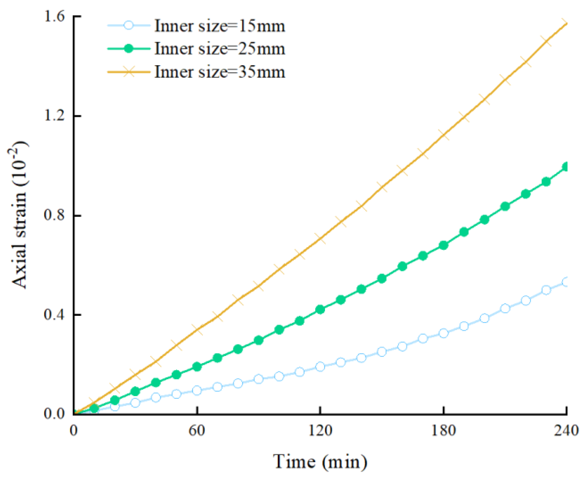
Figure 8 shows the axial-strain evolution curve of coal samples with different inner diameters under the stress-seepage coupling (taking samples in Group C as an example). By comparing the three curves, it can be found that for the sample with a large inner diameter, the strain of the sample increases significantly under the stress-seepage coupling effect, and the axial strain of the coal body reaches 0.0158 at 240 min. For the specimen with an inner diameter of 35 mm, the accelerated deformation stage is reached after 130 min. However, for the sample with the smallest inner diameter (15 mm), the accelerated deformation stage is not reached until 170 min later, and the axial strain after the test is only 0.0053. The reason for this phenomenon is that due to the longer seepage path and smaller water pressure gradient, the sample with a larger inner diameter has stronger resistance to the stress-seepage coupling effect.
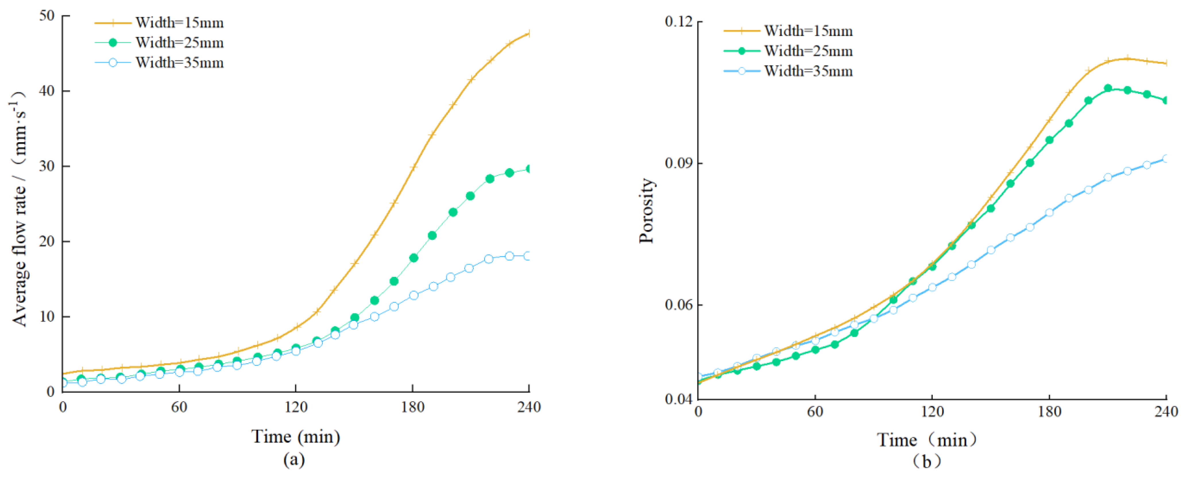
Figure 9a shows the change rule of the average velocity of coal sample with an inner diameter under the stress-seepage coupling (taking samples in Group C as an example). It can be seen that the larger the inner diameter of the coal sample, the larger the peak value of the average velocity. The reason is that with the increase in the inner diameter of the coal sample, the mechanical strength of the coal sample decreases continuously, the internal fractures of the coal and rock mass are well developed, and the seepage resistance gradually decreases. Besides, in the sample with a larger inner diameter, the fluid seepage path is shorter, the hydraulic pressure gradient is larger, and the flow velocity is faster. At the same time, it can be observed that the flow rate increases faster in coal samples with a larger inner diameter. This shows that the narrower the coal pillar is, the faster the water inrush occurs. Figure 9b shows the evolution law of the average porosity of coal samples with different inner diameters under the stress-seepage coupling. It can be observed that the larger the inner diameter of the coal sample, the faster the growth rate of porosity, and the greater the growth range. This is because in the process of stress-seepage coupling, the larger the inner diameter of coal sample, the lower the structural strength of the coal body, and the easier to form through cracks in its interior, resulting in a substantial increase in porosity. At the same time, the porosity decreases slowly in the late period of stress-seepage coupling (t > 200 min). This is because after the formation of through cracks, the rock mass continues to undergo compression deformation under the influence of stress loading, and the porosity decreases after reaching the peak.
4. Numerical Simulation of Stress-Seepage Coupling in the Coal Pillar
4.1. Simulation Schemes
The water-resisting coal pillar is located between the bottom transportation roadway and the shaft, which is an important structure to prevent the high-pressure mud from flowing into the bottom roadway. The mechanical and seepage characteristics of the water-resisting coal pillar are affected by many factors. To study the water-resisting capacity of the water-resisting coal pillar under different conditions, numerical simulation on coal rock under different water pressures and rock integrity was carried out in this section.
Three simulation schemes were designed in the study. Scheme I: the mechanical characteristics of the intact water-resisting coal pillar under the action of mining stress were simulated; Scheme II: the evolution of the mechanical and hydraulic characteristics of the intact water-resisting coal pillar under the stress-seepage coupling effect was simulated; Scheme III: the evolution of the mechanical and hydraulic characteristics of the water-resisting coal pillar with a large number of natural joints and fissures was simulated under the stress-seepage coupling effect. By comparing the simulation results of the above schemes, the appropriate width of the water-resisting coal pillar can be determined.
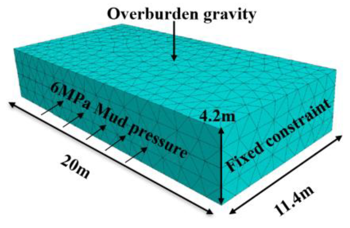
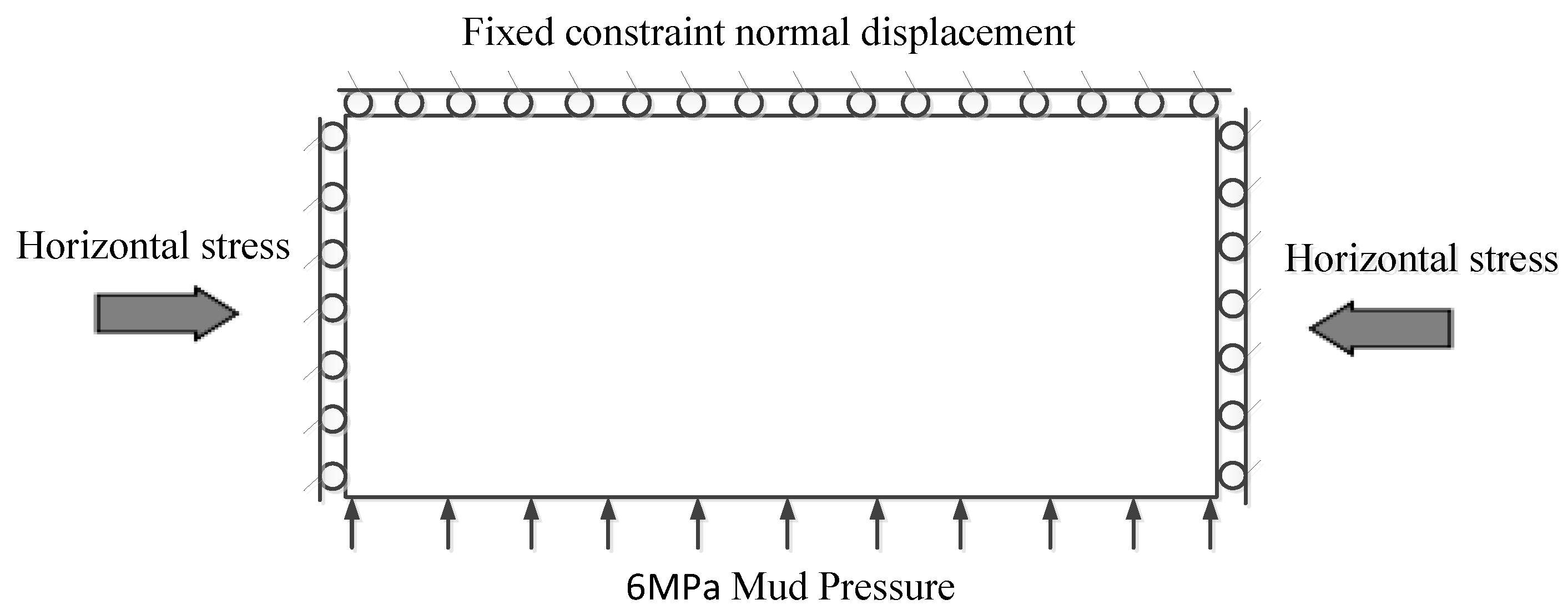
Taking the water-blocking coal pillars of the main and auxiliary inclined shafts of Kekegai Coal mine as the simulation object, the relevant numerical calculation model is established according to the engineering geology and hydrogeological conditions on site, as shown in Figure 10. The overall geometric size of the model is 11.4 × 20 × 4.2 m3. Stress and displacement boundary conditions: the front, back, and bottom boundaries of the model are fixed constraint normal displacement. According to the dead weight of overlying strata, a vertically downward uniform load of 5 MPa is applied to the top boundary of the model. In simulation schemes II and III, the water pressure of 6 MPa was set to the shaft wall. Both the applied water pressure boundary and the excavation roadway boundary are free boundaries, as shown in Figure 10 and Figure 11.
4.2. Simulation Results
- (1)
- Mechanical distribution characteristics of the intact water-resisting coal pillar under mining stress
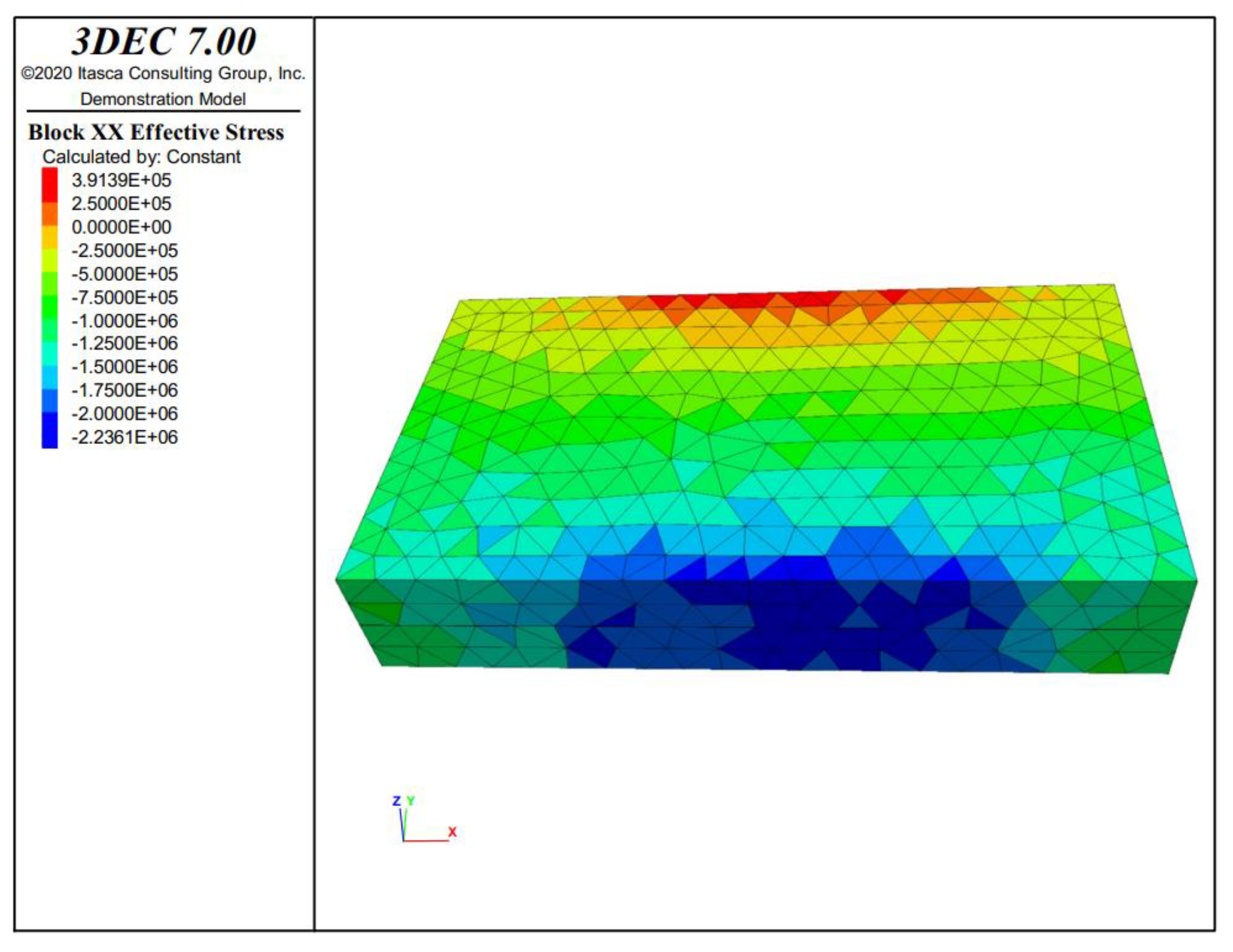
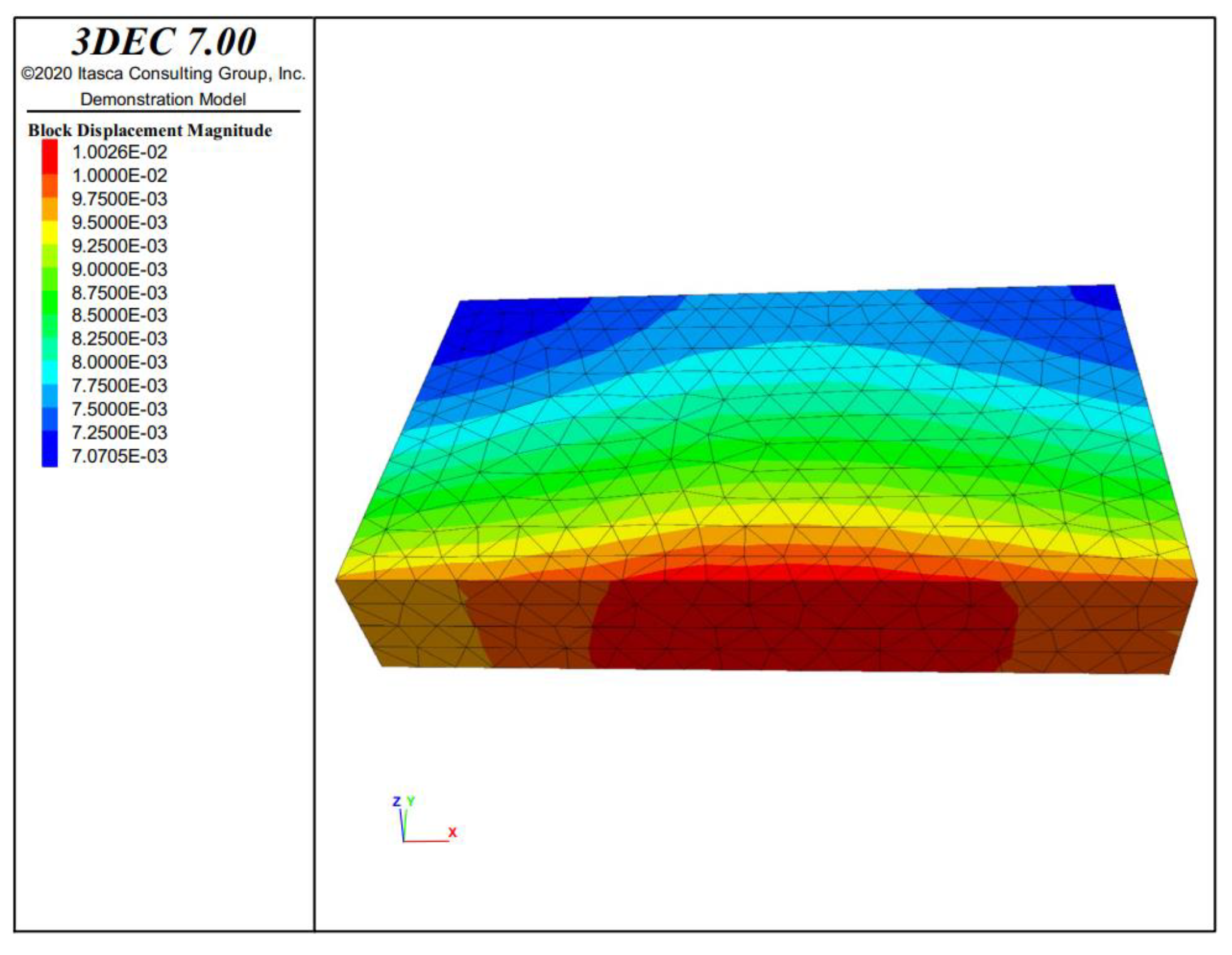
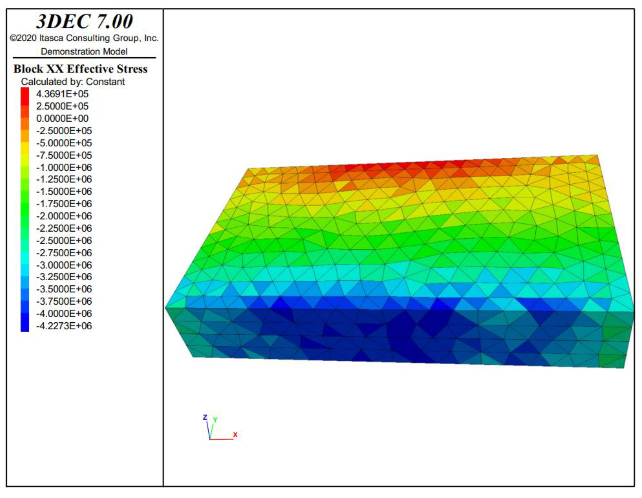
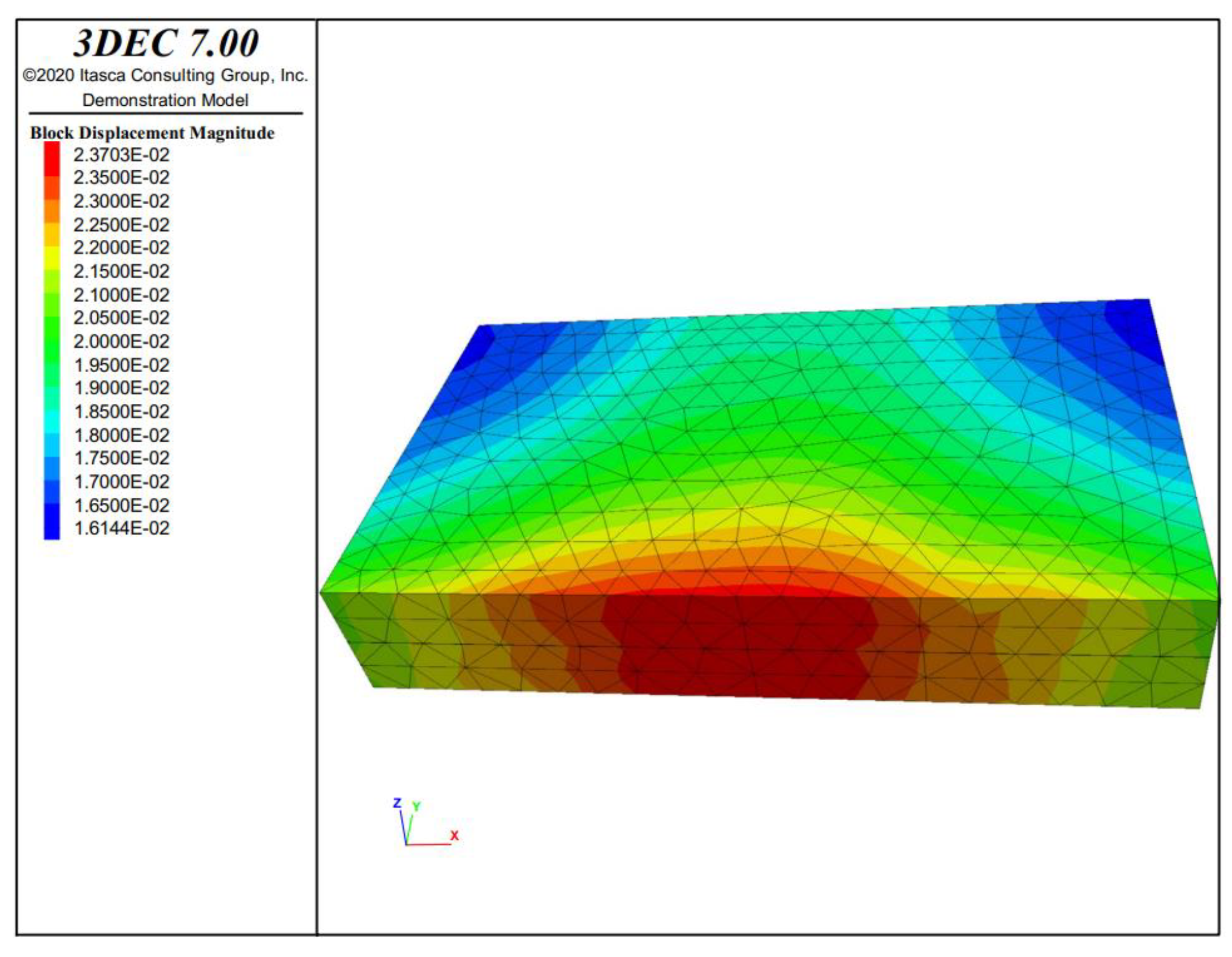
Figure 12 and Figure 13 show the stress and displacement distribution of the intact water-resisting coal pillar under mining stress. It can be concluded that the effective stress of the intact water-resisting coal pillar shows a significant non-uniform distribution. The coal pillar is subjected to compressive stress at the shaft wall and tensile stress at the boundary of the main roadway. From the shaft wall to the inside of the coal pillar, the compressive stress gradually decreases and decreases to zero at a certain position in the middle of the coal pillar. Under the interaction of high-water pressure and mining stress, there is an area with increased compressive stress at the shaft wall and an area with increased tensile stress at the main roadway wall. The maximum compressive stress on the coal pillar is 3 MPa, and the tensile stress is 0.338 MPa. Through the test, the average compressive strength of the intact water-resisting coal pillar is 21.52 MPa, and the tensile strength is 1.27 MPa. Therefore, the failure of the water-resisting coal pillar will not occur under this condition. As shown in Figure 12, the displacement of coal pillar also presents non-uniform spatial distribution. The displacement gradually increases from the roadway wall to the shaft wall. For the shaft wall and roadway wall, the displacement at the center is greater than that at both ends.
- (2)
- Distribution of mechanical characteristics of intact water-resisting coal pillar under the stress-seepage coupling
Figure 14 and Figure 15 depict the stress and displacement distribution of the intact water-resisting coal pillar under the stress-seepage coupling. It can be observed that the distribution mode of effective stress of the water-resisting coal pillar under the stress-seepage coupling is similar to that of the water-resisting coal pillar only under the influence of mining stress. Under the coupling effect of stress and seepage, there is an area with increased compressive stress at the shaft wall and an area with increased tensile stress at the main roadway wall. The maximum compressive stress of the coal pillar is 4.12 MPa, and the maximum tensile stress of the coal pillar is 0.378 MPa. However, the average saturated compressive strength and saturated tensile strength of the intact water-resisting coal pillar obtained through the test are 14 MPa and 0.6 MPa. Therefore, the failure of the water-resisting coal pillar will not occur under this condition. Comparing the simulation results of Scheme I and Scheme II, the maximum tensile stress value in Scheme II is much larger than that in Scheme I, and the tensile stress area of the coal pillar in Scheme II is 1.36 times of that in Scheme I. As shown in Figure 14, the displacement of the coal pillar presents non-uniform spatial distribution, and the displacement gradually increases from the roadway wall to the shaft wall. For the shaft wall and roadway wall, the center displacement is greater than that in the two ends. Through the above comparison, it can be concluded that the stress-seepage coupling effect has a significant impact on the stability of the intact water-resisting coal pillar.
- (3)
- Distribution of mechanical characteristics of the water-resisting coal pillar with fractures under the stress-seepage coupling
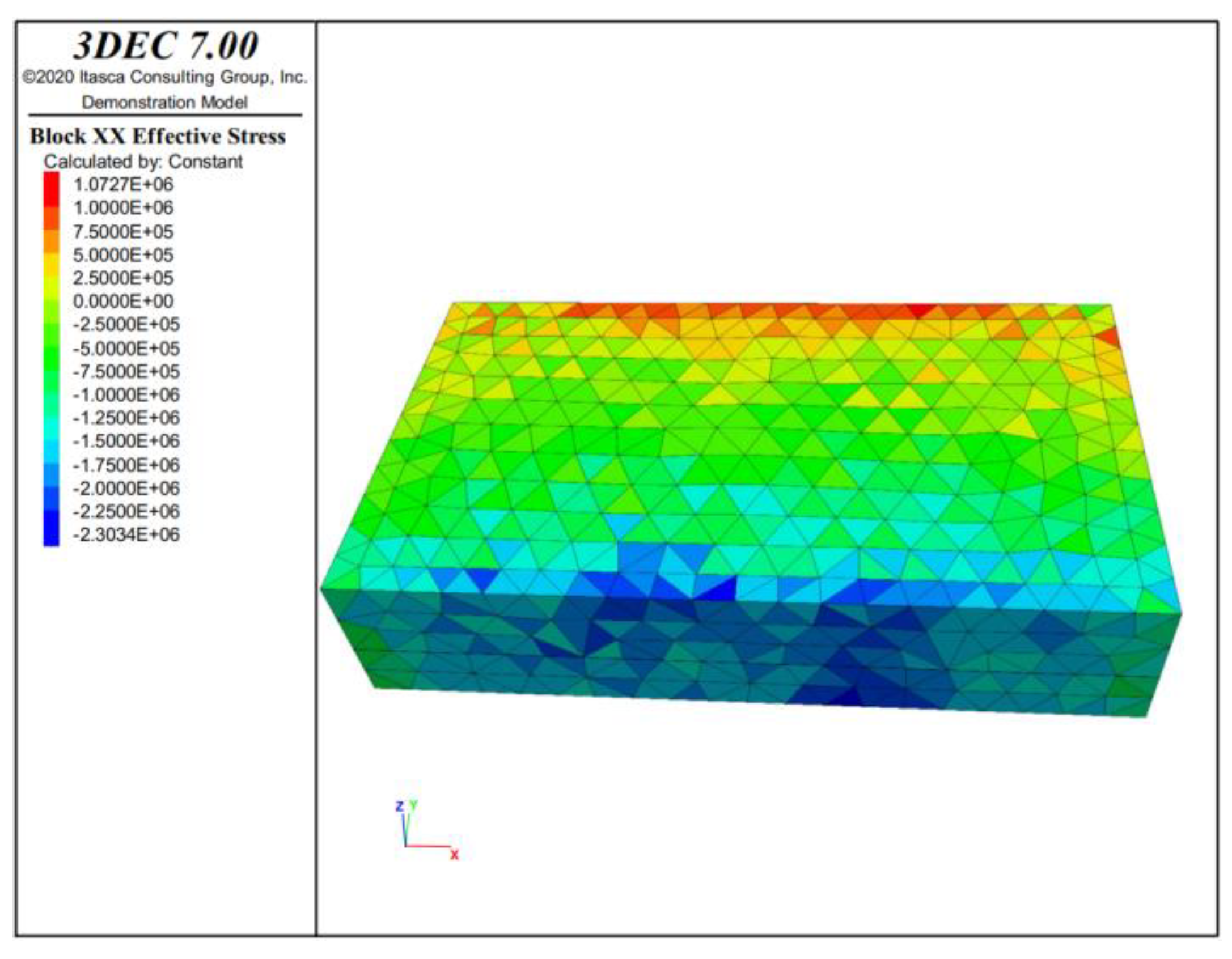
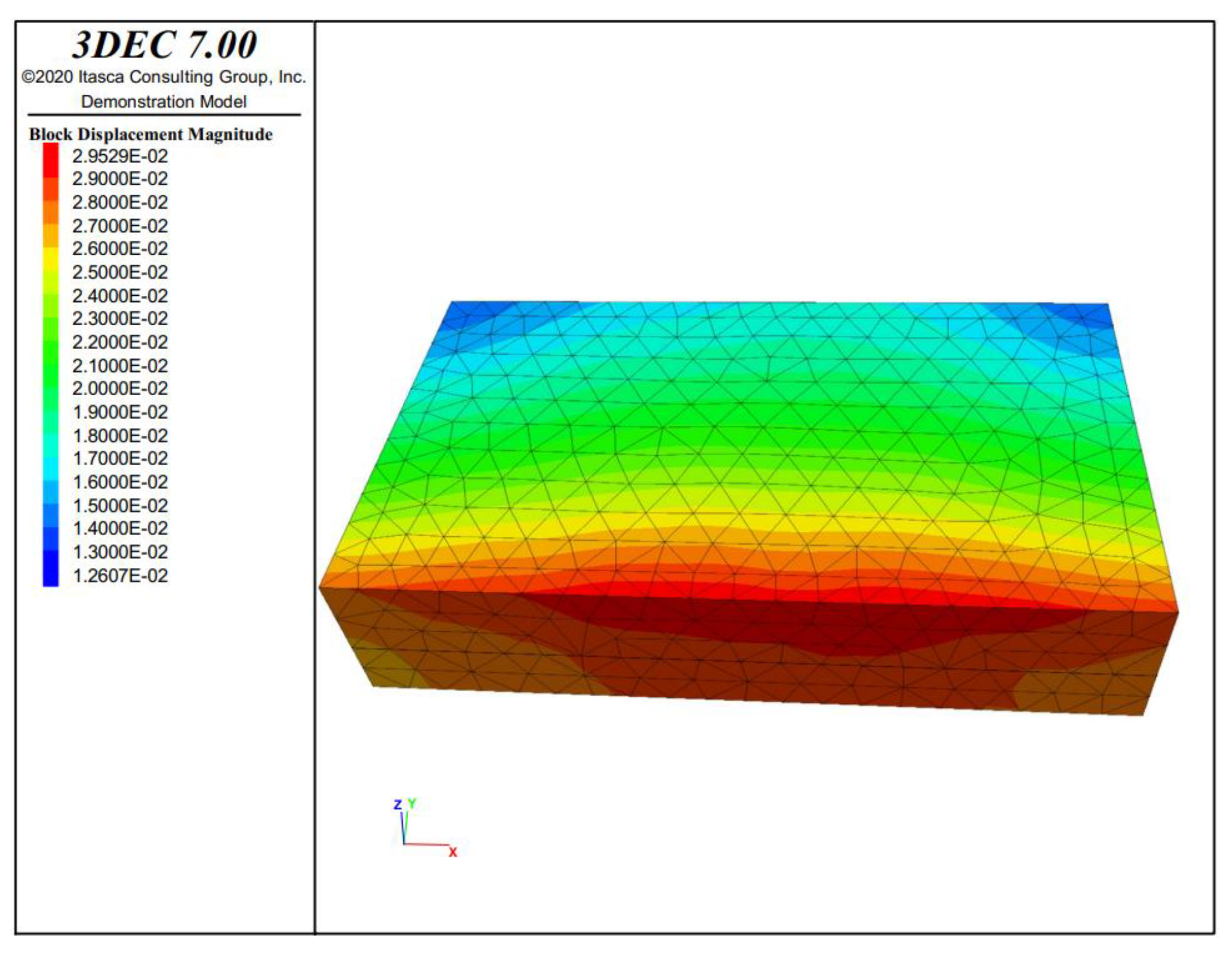
Figure 16 and Figure 17 show the stress and displacement distribution of the water-resisting coal pillar with natural fissures under the stress-seepage coupling effect. The maximum compressive stress and the tensile stress of the coal pillar are 4.23 MPa and 1.072 MPa, respectively. The test results show that the average compressive strength and tensile strength of the water-resisting coal pillar with a large number of natural joint fissures under the stress-seepage coupling action are 14 MPa and 0.6 MPa, respectively. Therefore, under this condition, the wall of the coal pillar roadway is unstable under tension, and the failure of the water-resisting coal pillar occurs. As presented in Figure 16, the displacement inside the coal pillar is significantly different. The closer to the shaft wall, the greater the displacement. Besides, the displacement at both ends of the coal pillar is smaller than that at the center, regardless of whether it is the inner wall of the shaft or the inner wall of the roadway. The above results show that under the stress-seepage coupling effect, the bearing capacity of the water-resisting coal pillar with nature fissures is poor, and the natural fissures can reduce the mechanical properties of the rock. These fissures continue to expand under the stress-seepage coupling effect, and eventually develop into through fractures, leading to the failure of the coal pillar and water inrush accidents.
To sum up, the effective stress and displacement of the water-resisting coal pillar show non-uniform spatial distribution under the three schemes. The coal pillar is subjected to compressive stress at the shaft wall and tensile stress at the boundary of the main roadway. There is a stress increase area at the shaft wall and a tensile stress increase area at the roadway wall. The water-resisting coal pillar with a large number of natural joint fissures will be damaged under the stress-seepage coupling, while the coal pillar will not be damaged under other conditions. Considering both the stress-seepage coupling effect and the natural fracture of the coal pillar, the stability of the water-resisting coal pillar in the Kekegai coal mine is poor and the coal pillar is prone to failure.
5. Determination of the Reserved Width of the Water-Resisting Coal Pillar under the Stress-Seepage Coupling
According to the numerical simulation results in the previous section, when there are stress-seepage coupling effect and the natural fracture of the water-resisting coal pillar, the wall area of the water-resisting pillar roadway will be subject to tensile failure, which will lead to water inrush accidents. Therefore, the existing coal pillar width cannot meet the needs of the project. To solve this problem, the damage coefficient is introduced in this section to evaluate the stability of the water-resisting coal pillars with different widths. The evaluation results are combined with the test and numerical simulation results to determine the reserved width of the water-resisting coal pillars under the stress-seepage coupling effect.
In the detailed rules for water prevention and control of coal mines, the following provisions are reserved for the width of the water-resisting coal pillars:
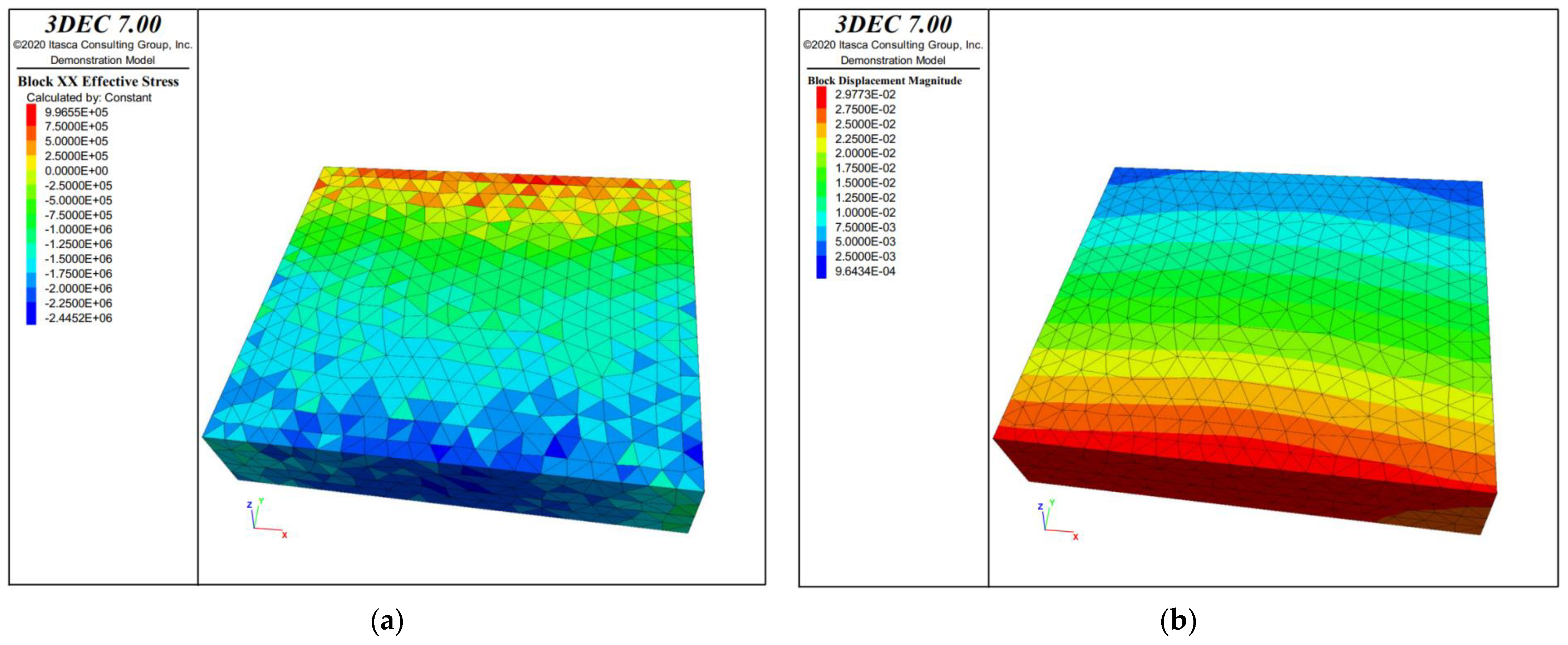
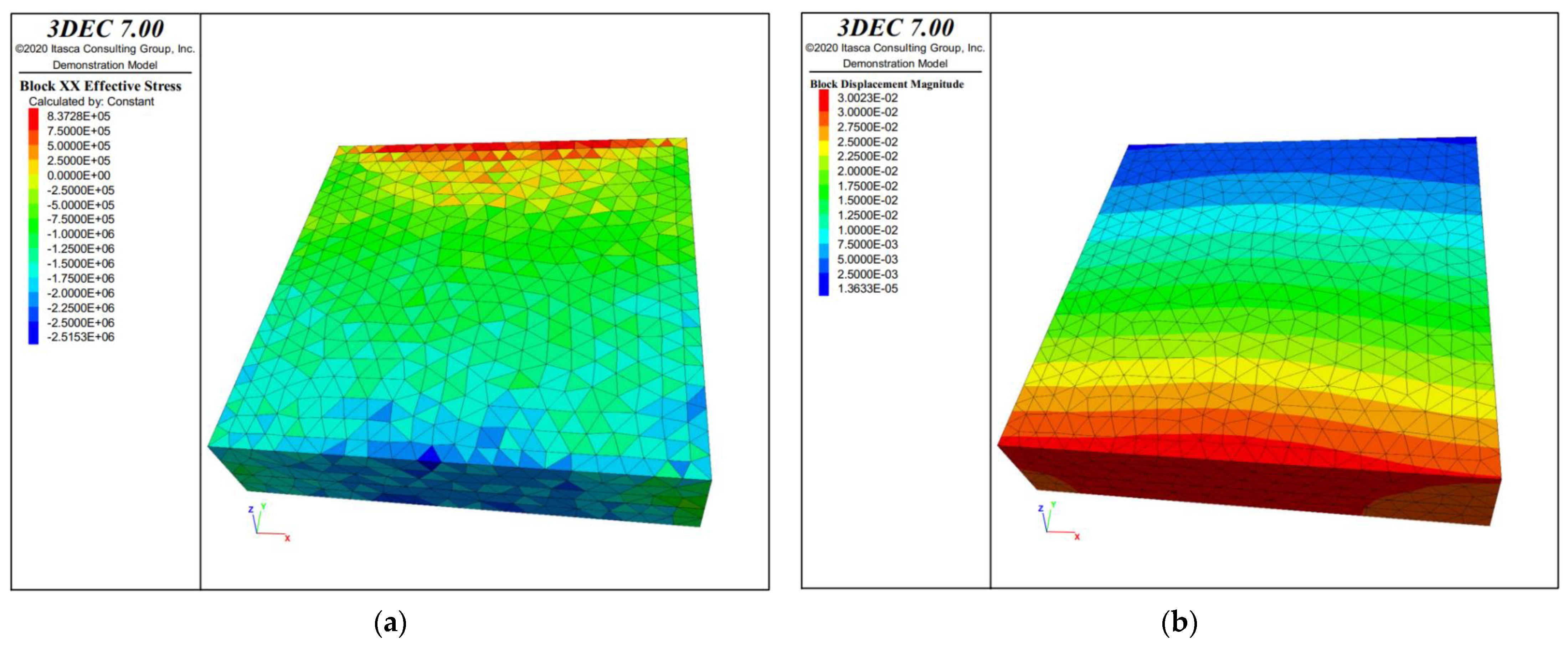
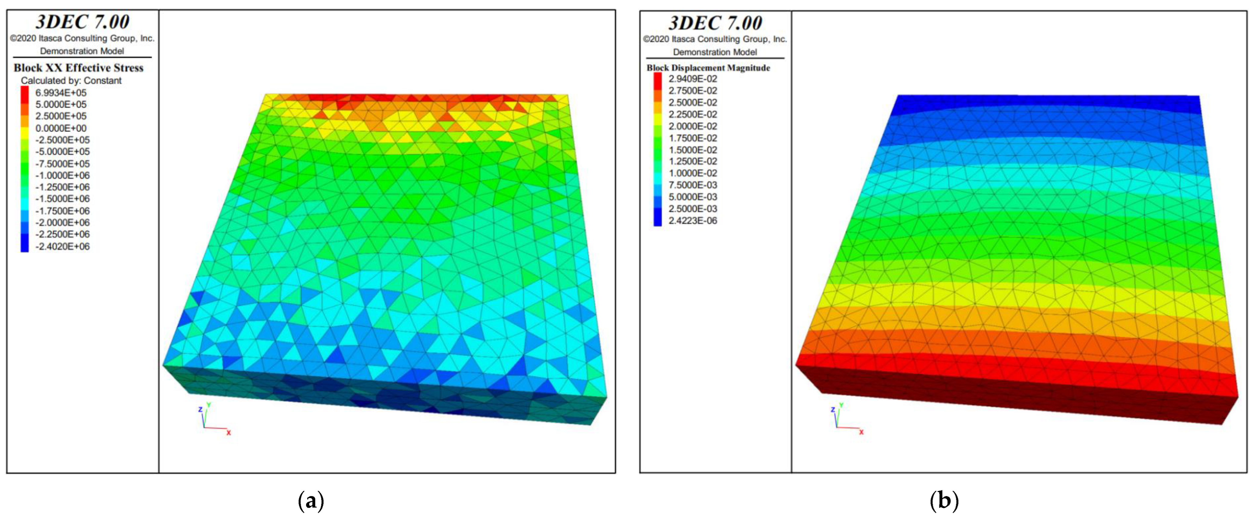
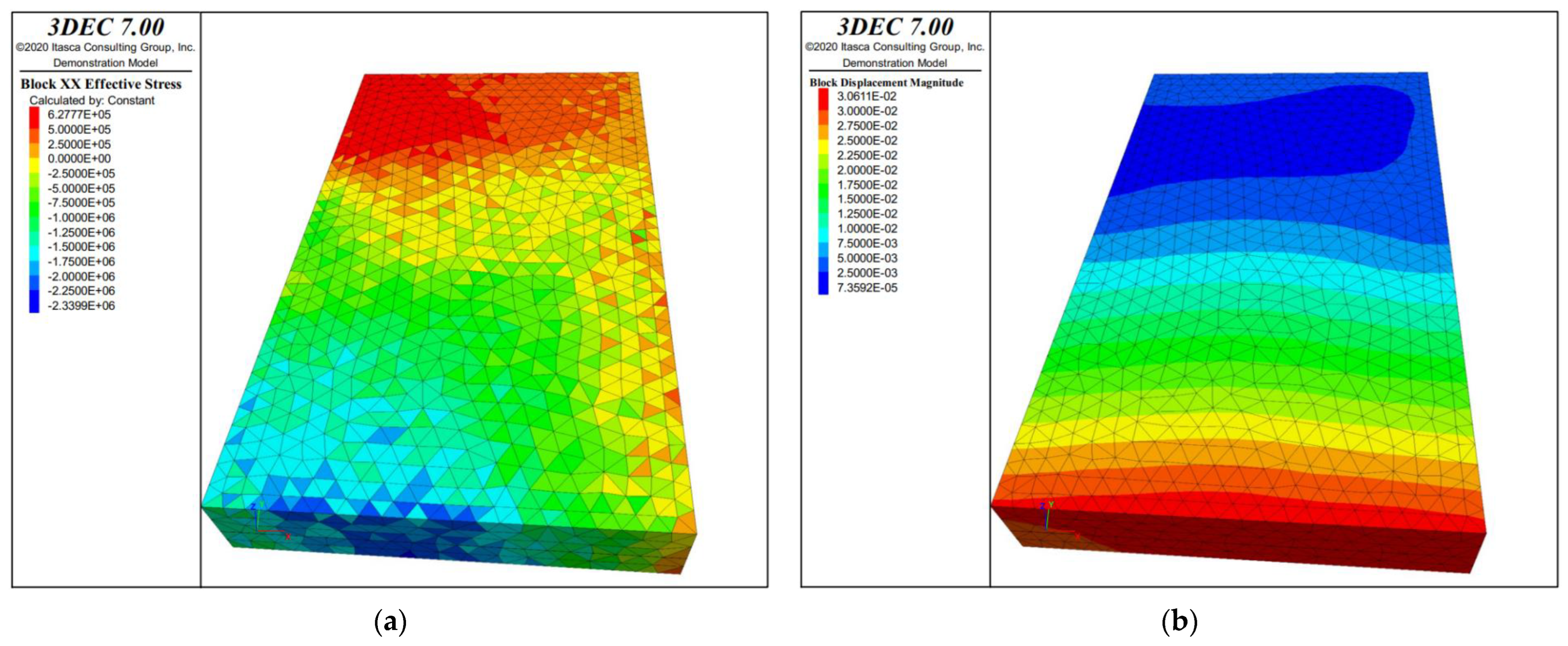
where K is the safety factor, ranging from 2 and 4. According to the above equation, the width L of the water-resisting pillar should be between 15.82–31.62 m. According to the above interval, 3DEC numerical simulation of the coal pillar with different widths is carried out, and the effective stress and displacement distribution results of coal pillars with joints and fissures under different coal pillar widths are calculated, as shown in Figure 18, Figure 19, Figure 20, Figure 21 and Figure 22.
It can be seen from Figure 18, Figure 19, Figure 20, Figure 21 and Figure 22 that after the water-resisting coal pillar is reserved, the stress of the coal pillar shows a significant non-uniform distribution due to the influence of the overburden movement and evolution height. To further analyze the stability characteristics of the coal pillar in the above results, the damage variable is introduced to describe the fracture development. The damage variable can be used to reflect the internal defects of the coal body, and the essence of the sliding instability of the coal pillar on the macro level is the result of the damage accumulation of internal micro units. The damage variable D of the water-resisting coal pillar can be calculated by the following equation:
where SD is the number of the failure nodes; SO is the total number of nodes. When D = 0, the coal pillar is not affected by its internal stress distribution; When D is closer to 1, it indicates that the failure and instability risk of the coal pillar is higher.
By using the node statistics function in 3DEC software, the number of nodes with damage and failure (that is, the tensile stress exceeds the tensile strength of coal and rock) is counted in the above stress-displacement distribution diagram, and the damage variables of the water-resisting coal pillars with different widths are calculated. Figure 23 shows the specific calculation results.
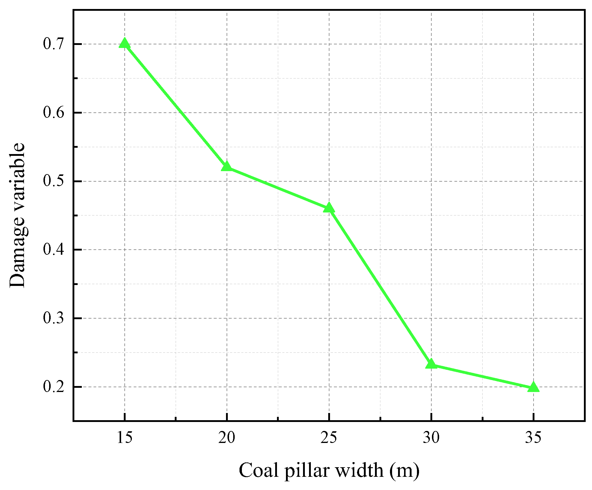
Figure 23 shows the calculated results of the damage variable of coal pillars with different widths. It can be seen that the damage variable of the water-resisting coal pillar decreases with the increase in coal pillar width. The results of the previous research [42,43] have shown that when the damage variable of the water-resisting coal pillar is 0.25 and below, the coal pillar is in a safe state. Under this condition, the number of cracks in the coal body under the stress-seepage coupling effect is less. According to this point of view, it is determined that the reasonable width interval for the water-resisting coal pillar is 28.3–31.62 m. This value will be further analyzed from the following three aspects: maximum tensile stress, porosity, and flow velocity.
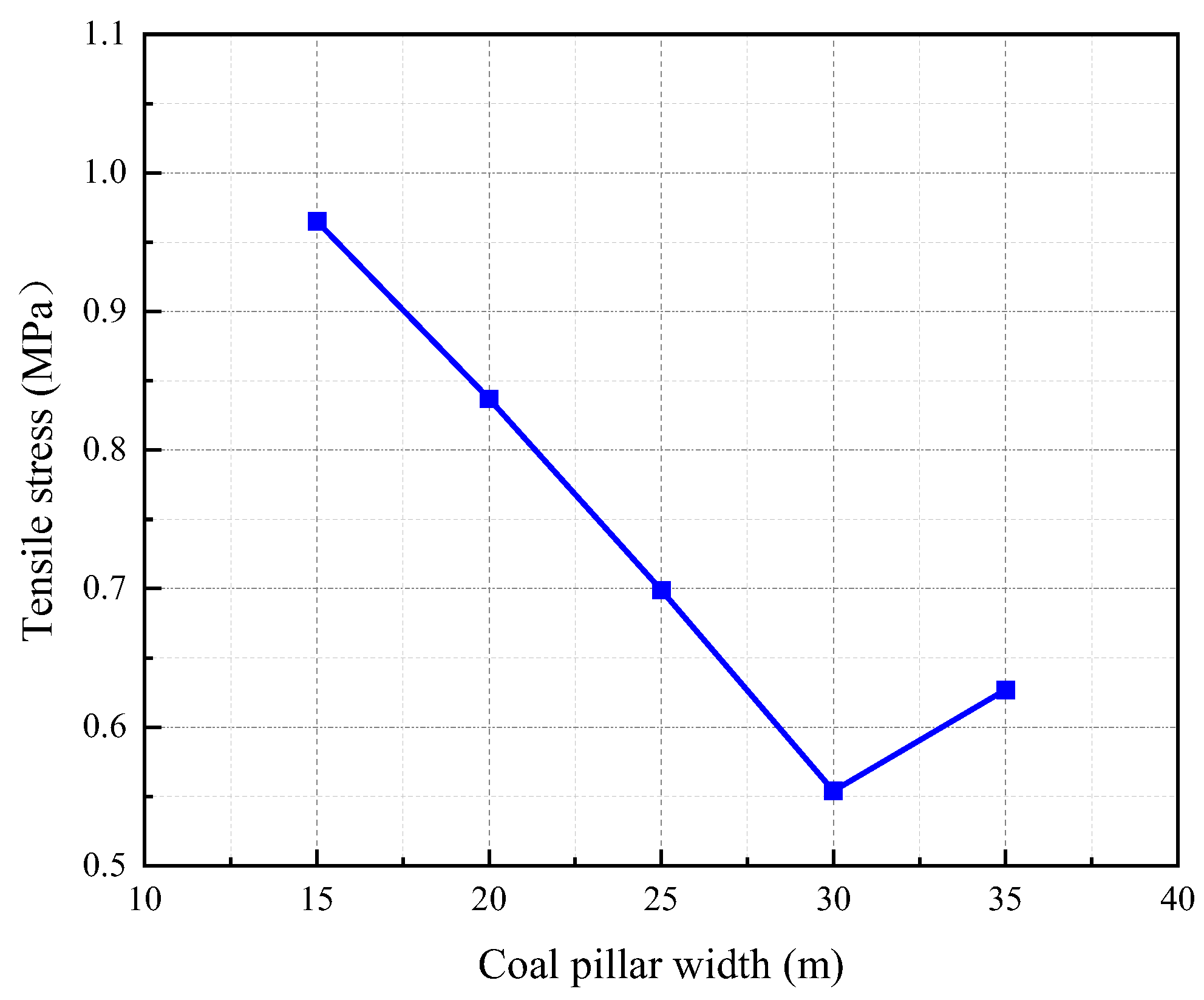
Figure 24 shows the results of the maximum tensile stress of coal pillars with different widths. With the increase in the width of the water-resisting coal pillar, the maximum tensile stress inside the coal pillar decreases as a whole. However, in the width interval of 30–35 m, the tensile stress increases rapidly. When the width of the water-resisting coal pillar is 28.3–31.62 m, the maximum tensile stress of the coal pillar is 0.58 MPa, which is less than its saturated tensile strength of 0.6 MPa. This means that the coal pillar will not be unstable or damaged.
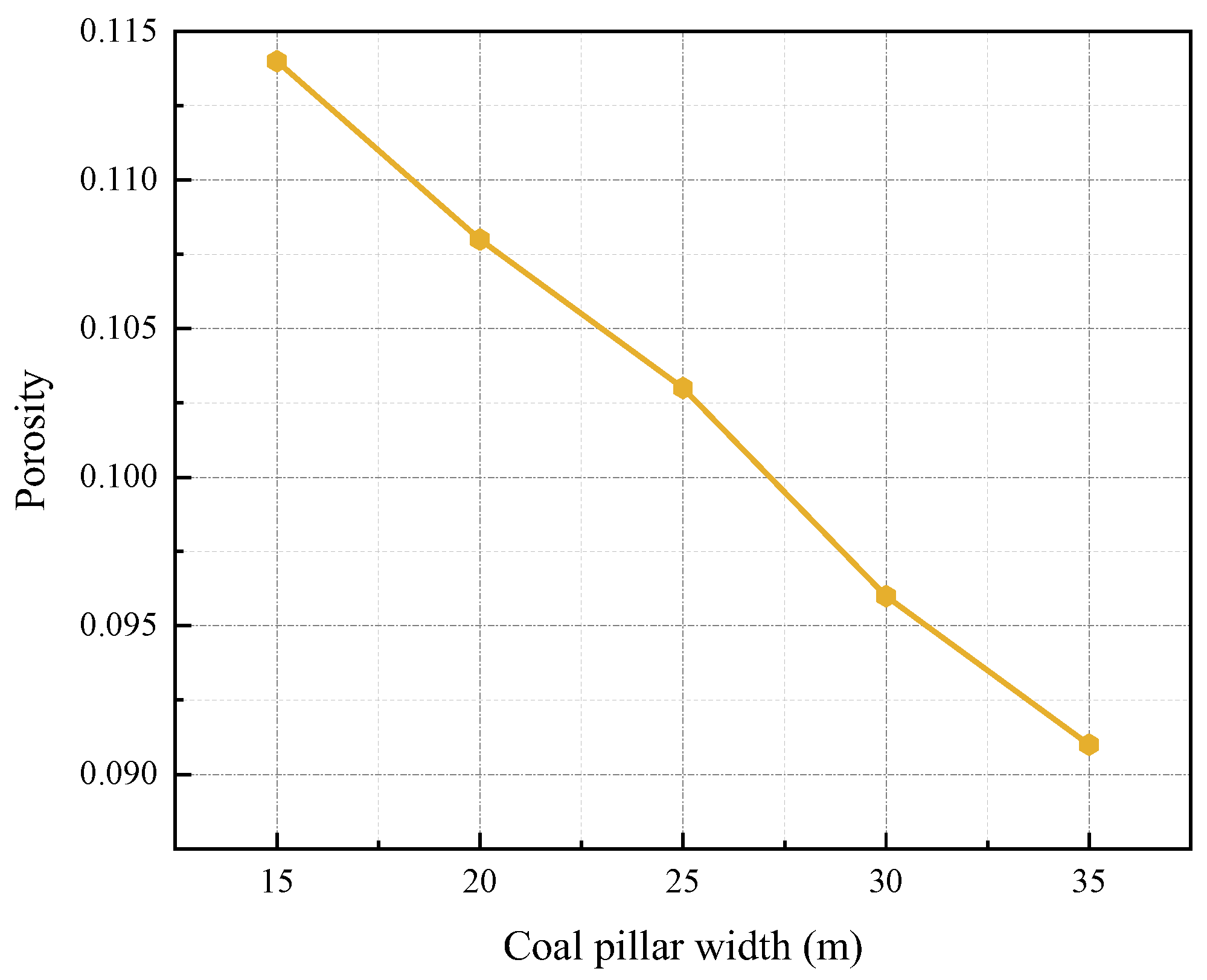
Figure 25 shows the porosity results of coal pillars with different widths. It can be seen that the porosity of the water-resisting coal pillar decreases gradually with the increase in coal pillar width. It indicates that with the increase in coal pillar width, the water-resisting coal pillar is safer and the risk of water inrush is smaller. When the width of the water-resisting coal pillar is 28.3–31.62 m, the porosity in the coal pillar is less than 0.0975, and the coal pillar has a high-water resistance.
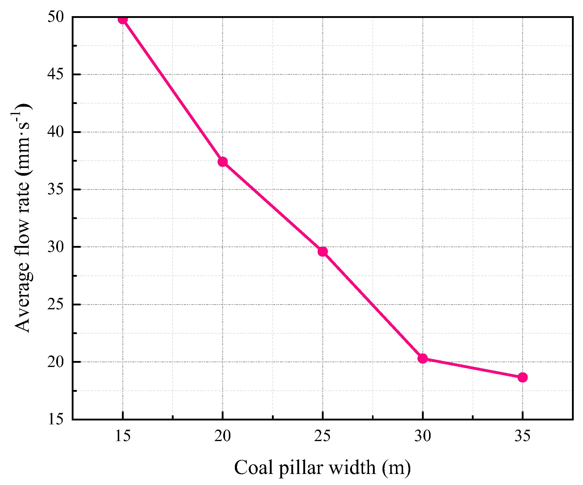
Figure 26 depicts the average flow velocity values of the water-resisting coal pillars with different widths. It can be seen that the average velocity inside the water-resisting coal pillar decreases gradually with the increase in coal pillar width. This shows that the wider the coal pillar, the stronger the water-resisting capacity of the water-resisting coal pillar, and the lower the risk of water inrush. When the width of the water-resisting coal pillar is 28.3–31.62 m, the average velocity in the coal pillar is about 25 mm/s. At this time, the risk of water inrush from the coal pillar is extremely low.
From the above analysis, it is obtained that the width of the water-resisting pillar should be set between 28.3–31.62 m. To effectively save coal resources, the design width of the water-resisting coal pillar should be reduced as much as possible. However, considering the influence of mud on the stress-seepage coupling effect of the internal cracks of the water-resisting coal pillar, the width of the coal pillar needs to be appropriately increased to ensure safety. The safety factor of the water-resisting coal pillar is set as 1.08, and the reasonable value of the width of the water-resisting coal pillar can be obtained as 30.57 m.
The water-resisting coal pillar with the determined width of 30.57 m is verified by the shear slip law of the coal body. The shear slip equation of coal pillars can be described as follows:
where τ is the shear stress along the fault plane; μ is the friction coefficient in the fault plane; σ is the normal stress on fault plane (the value of the compression stress is positive, while the value of the tensile stress is negative); ρ is the tensile stress generated by the interstices in the crust (the value of the compression stress is positive, while the value of the tensile stress is negative); C is the cohesive stress.
Through the calculation results, it is concluded that under the stress-seepage coupling action, no shear slip under Coulomb fracture stress will occur for the water-resisting coal pillar of this width, which verifies the reliability of the calculation method proposed in this study.
6. Conclusions
To analyze the failure characteristics of the water-resisting coal pillar under the stress-seepage coupling effect, a series of stress-seepage coupling tests of the surrounding rock of the shaft were carried out, and the evolution law of the stress-seepage coupling characteristics of coal rock under the action of high-pressure mud was analyzed. The numerical simulation of water inrush in the shaft under different conditions was carried out to study the water-resisting ability of the water-resisting coal pillar under different conditions; The damage coefficient was introduced to evaluate the stability of the water-resisting coal pillars with different widths, and the reserved width of the water-resisting coal pillars under the coupling effect of stress and seepage was determined. The main conclusions are as follows:
The test results show that the stress-seepage coupling characteristics of coal samples are greatly affected by water content and coal pillar width. Under the stress-seepage coupling effect, the peak strength of coal samples with higher water content is lower, the failure process of the coal pillar is more complex, and the axial strain, average velocity and porosity increase more significantly. The larger the inner diameter of the coal sample, the lower the peak strength, and the greater and faster the axial strain, average velocity, and porosity increase. This shows that the higher the water content and the narrower the width of the coal pillar, the higher the risk of coal pillar damage and water inrush.
Through numerical simulation, it is found that the effective stress and displacement of the water-resisting coal pillar under the three schemes show non-uniform distribution. The coal pillar is subjected to compressive stress at the shaft wall and tensile stress at the boundary of the main roadway. The tensile stress area of the coal pillar in Scheme II is significantly larger than that in Scheme I, which indicates that the stress-seepage coupling effect has a significant impact on the stability of the intact water-resisting coal pillar. In addition, the intact water-resisting coal pillar under mining stress and the intact water-resisting coal pillar under the stress-seepage coupling action are free from coal pillar failure. However, the failure of the water-resisting coal pillar with a large number of natural joints and fissures occurs under the stress-seepage coupling action.
The numerical simulation of the water-resisting coal pillar with different reserved widths has a certain guiding significance for engineering practice. The simulation results show that with the increase in the width of the water-resisting coal pillar, the internal damage variable, maximum tensile stress, porosity, and average flow velocity of the coal pillar decrease, the water-resisting coal pillar is safer and the risk of water inrush decreases. According to the simulation results of damage variable, maximum tensile stress, porosity, and flow velocity, the width of the water-resisting coal pillar under the stress-seepage coupling are determined. Finally, this result is validated by the shear slip law of the coal body, which verifies the reliability of the proposed calculation method of coal pillar width in this study.
Author Contributions
Conceptualization, Funding acquisition, Project administration, Resources, D.M.; Data curation, Formal analysis, Investigation, Visualization, Writing—original draft, Q.L. (Quanhui Liu); Methodology, Software, Writing—review and editing, Y.X.; Supervision, Validation, Q.L. (Qiang Li). All authors have read and agreed to the published version of the manuscript.
Funding
This study was supported by the National Science Fund for Excellent Young Researchers of China (52122404) and the National Natural Science Foundation of China (41977238).
Data Availability Statement
Data is contained within the article.
Conflicts of Interest
The authors declare no conflict of interest.
References
- Wen, Z.; Xia, Y.P.; Ji, Y.G.; Liu, Y.M.; Xiong, Z.M.; Lu, H. Study on risk control of water inrush in tunnel construction period considering uncertainty. J. Civ. Eng. Manag. 2019, 25, 757–772. [Google Scholar] [CrossRef]
- Jose, M.-M.F.; Fernando, D.-R.; Jesus, G.-Z.; Wenceslao, M.-R.; Manuel, L.-C.; Lourdes, G.-C. Identification of leakage and potential areas for internal erosion combining ERT and IP techniques at the Negratin Dam left abutment (Granada, southern Spain). Eng. Geol. 2018, 240, 74–80. [Google Scholar]
- Bo, K.; Wang, M.S.; Zhao, Z.Q. Numerical simulation on bottom hole flow fields of reverse circulation bit. Appl. Mech. Mater. 2013, 256–259, 2826–2830. [Google Scholar] [CrossRef]
- Zhang, J.C. Investigations of water inrushes from aquifers under coal seams. Int. J. Rock Mech. Min. Sci. 2005, 42, 350–360. [Google Scholar] [CrossRef]
- Ma, D.; Duan, H.Y.; Zhang, J.X.; Bai, H.B. A state-of-the-art review on rock seepage mechanism of water inrush disaster in coal mines. Int. J. Coal Sci. Technol. 2022, 9, 50. [Google Scholar] [CrossRef]
- Li, C.; He, S.F.; Hou, W.T.; Ma, D. Experimental study on expansion and cracking properties of static cracking agents in different assembly states. Int. J. Min. Sci. Technol. 2022, 32, 1259–1272. [Google Scholar] [CrossRef]
- Ganji, H.T.; Alembagheri, M. Stability of monolithic gravity dam located on heterogeneous rock foundation. Arab. J. Sci. Eng. 2018, 43, 1777–1793. [Google Scholar] [CrossRef]
- Guo, X.; Chai, J.R.; Qin, Y.; Xu, Z.G.; Fan, Y.N.; Zhang, X.W. Mechanism and treatment technology of three water inrush events in the Jiaoxi River Tunnel in Shaanxi, China. J. Perform. Constr. Facil. 2019, 33, 04018098. [Google Scholar] [CrossRef]
- Chen, L.; Zhang, D.S.; Yao, N.; Wang, L.; Fan, G.W.; Wang, X.F.; Zhang, W. Coupling influence of inclination angle and moisture content on mechanical properties and microcrack fracture of coal specimens. Lithosphere 2022, 2021, 6226445. [Google Scholar] [CrossRef]
- Hosseinzadeh, A.; Nobarinasab, M.; Soroush, A.; Lotfi, V. Coupled stress-seepage analysis of Karun III concrete arch dam. Proc. Inst. Civ. Eng. Geotech. Eng. 2013, 166, 483–501. [Google Scholar] [CrossRef]
- Chen, L.W.; Feng, X.Q.; Xie, W.P.; Zeng, W.; Zheng, Z.Y. Using a fluid-solid coupled numerical simulation to determine a suitable size for barrier pillars when mining shallow coal seams beneath an unconsolidated, confined aquifer. Mine Water Environ. 2017, 36, 67–77. [Google Scholar] [CrossRef]
- Ma, Q.; Zhang, Y.D.; Gao, L.S.; Li, Z.X.; Song, G.Y.; Zheng, Y. The optimization of coal pillars on return air sides and the reasonable horizon layout of roadway groups in highly gassy mines. Sustainability 2022, 14, 9417. [Google Scholar] [CrossRef]
- Hu, M.L.; Zhao, W.L.; Lu, Z.; Ren, J.X.; Miao, Y.P. Research on the reasonable width of the waterproof coal pillar during the mining of a shallow coal seam located close to a reservoir. Adv. Civ. Eng. 2019, 2019, 3532784. [Google Scholar] [CrossRef]
- Ma, D.; Duan, H.Y.; Zhang, J.X. Solid grain migration on hydraulic properties of fault rocks in underground mining tunnel: Radial seepage experiments and verification of permeability prediction. Tunn. Undergr. Space Technol. 2022, 126, 104525. [Google Scholar] [CrossRef]
- Chen, S.H.; Zhang, Z.H. Determination of coal pillar width and support parameters in deep coal mines—A case study. J. Test. Eval. 2019, 47, 3160–3173. [Google Scholar] [CrossRef]
- Wang, B.N.; Dang, F.N.; Gu, S.C.; Huang, R.B.; Miao, Y.P.; Chao, W. Method for determining the width of protective coal pillar in the pre-driven longwall recovery room considering main roof failure form. Int. J. Rock Mech. Min. Sci. 2020, 130, 104340. [Google Scholar] [CrossRef]
- Jaiswal, A.; Shrivastva, B.K. Numerical simulation of coal pillar strength. Int. J. Rock Mech. Min. Sci. 2009, 46, 779–788. [Google Scholar] [CrossRef]
- Dong, Y.; Huang, Y.C.; Du, J.F.; Zhao, F. Study on overburden stability and development height of water flowing fractured zone in roadway mining with cemented backfill. Shock Vib. 2021, 2021, 6661168. [Google Scholar] [CrossRef]
- Das, A.J.; Mandal, P.K.; Paul, P.S.; Sinha, R.K.; Tewari, S. Assessment of the strength of inclined coal pillars through numerical modelling based on the ubiquitous joint model. Rock Mech. Rock Eng. 2019, 52, 3691–3717. [Google Scholar] [CrossRef]
- Shi, L.Q.; Wang, Y.; Qiu, M.; Han, L.; Zhao, Y.P. Research on the required width of a fault waterproof coal pillar based on underground pressure control theory. Arab. J. Geosci. 2019, 12, 480. [Google Scholar] [CrossRef]
- Li, A.; Ji, B.N.; Ma, Q.; Liu, C.Y.; Wang, F.; Ma, L.; Mu, P.F.; Mou, L.; Yang, Y.X.; Ding, X.S. Design of longwall coal pillar for the prevention of water inrush from the seam floor with through fault. Geofluids 2021, 2021, 5536235. [Google Scholar] [CrossRef]
- Wang, R.; Bai, J.B.; Yan, S.; Pan, G.Q.; Zhang, D.; Zhu, Q.C. Structure partition and reasonable width determination of waterproof coal pillar in strip mining. Lithosphere 2021, 2021, 3339797. [Google Scholar] [CrossRef]
- Wang, Y.Q.; Wang, X.; Zhang, J.S.; Yang, B.S.; Zhu, W.J.; Wang, Z.P. Similar experimental study on retaining waterproof coal pillar in composite strata mining. Sci Rep. 2022, 12, 1366. [Google Scholar] [CrossRef] [PubMed]
- Mathey, M.; van der Merwe, J.N. Critique of the South African squat coal pillar strength formula. J. S. Afr. Inst. Min. Metall. 2016, 116, 291–299. [Google Scholar] [CrossRef]
- Yao, Q.L.; Yu, L.Q.; Chen, N.; Wang, M.N.; Xu, Q. Experimental study on damage and failure of coal-pillar dams in coal mine underground reservoir under dynamic load. Geofluids. 2021, 2021, 5623650. [Google Scholar] [CrossRef]
- Bukowski, P. Water hazard assessment in active shafts in Upper Silesian Coal Basin Mines. Mine Water Environ. 2011, 30, 302–311. [Google Scholar] [CrossRef]
- Ma, D.; Duan, H.Y.; Zhang, J.X.; Liu, X.W.; Li, Z.H. Numerical simulation of water–silt inrush hazard of fault rock: A three-phase flow mode. Rock Mech. Rock Eng. 2022, 55, 5163–5182. [Google Scholar] [CrossRef]
- Huo, Q.; Li, Z.; Ye, Q.Q. Research on the mechanism of water inrush disaster in the construction of tunnel based on the aquifer inrush model. In Proceedings of the 2nd International Conference on Civil Engineering (ICCEHB 2011), Shijiazhuang, China, 16–18 December 2011. [Google Scholar]
- Kerimov, A.; Mavko, G.; Mukerji, T.; Dvorkin, J.; Al Ibrahim, M.A. The influence of convex particles’ irregular shape and varying size on porosity, permeability, and elastic bulk modulus of granular porous media: Insights from numerical simulations. J. Geophys. Res. Solid Earth 2018, 123, 10563–10582. [Google Scholar] [CrossRef]
- Ma, D.; Miao, X.X.; Bai, H.B.; Huang, J.H.; Pu, H.; Wu, Y.; Zhang, G.M.; Li, J.W. Effect of mining on shear sidewall groundwater inrush hazard caused by seepage instability of the penetrated karst collapse pillar. Nat. Hazards 2016, 82, 73–93. [Google Scholar] [CrossRef]
- Chen, J.T.; Zhao, J.H.; Zhang, S.C.; Zhang, Y.; Yang, F.; Li, M. An experimental and analytical research on the evolution of mining cracks in deep floor rock mass. Pure Appl. Geophys. 2020, 177, 5325–5348. [Google Scholar] [CrossRef]
- Liang, D.X.; Jiang, Z.Q.; Zhu, S.Y.; Sun, Q.; Qian, Z.W. Experimental research on water inrush in tunnel construction. Nat. Hazards 2016, 81, 467–480. [Google Scholar] [CrossRef]
- Ma, D.; Duan, H.Y.; Li, X.B.; Li, Z.H.; Zhou, Z.L.; Li, T.B. Effects of seepage-induced erosion on nonlinear hydraulic properties of broken red sandstones. Tunn. Undergr. Space Technol. 2019, 91, 102993. [Google Scholar] [CrossRef]
- Li, Q.; Ma, D.; Zhang, Y.D.; Liu, Y.; Ma, Y.J. Insights into controlling factors of pore structure and hydraulic properties of broken rock mass in a geothermal reservoir. Lithosphere 2022, 2021, 3887832. [Google Scholar] [CrossRef]
- Yin, S.X.; Zhang, J.C.; Liu, D.M. A study of mine water inrushes by measurements of in situ stress and rock failures. Nat. Hazards 2015, 79, 1961–1979. [Google Scholar] [CrossRef]
- Ma, D.; Kong, S.B.; Li, Z.H.; Zhang, Q.; Wang, Z.H.; Zhou, Z.L. Effect of wetting-drying cycle on hydraulic and mechanical properties of cemented paste backfill of the recycled solid wastes. Chemosphere 2021, 282, 131163. [Google Scholar] [CrossRef]
- Ma, D.; Zhang, J.X.; Duan, H.Y.; Huang, Y.L.; Li, M.; Sun, Q.; Zhou, N. Reutilization of gangue wastes in underground backfilling mining: Overburden aquifer protection. Chemosphere 2021, 264, 128400. [Google Scholar] [CrossRef] [PubMed]
- Behrenbruch, P.; Biniwale, S. Characterisation of clastic depositional environments and rock pore structures using the Carman-Kozeny equation: Australian sedimentary basins. J. Pet. Sci. Eng. 2005, 47, 175–196. [Google Scholar] [CrossRef]
- Li, C.Y.; Cui, C.Y.; Lei, G.R.; Zuo, J.P.; Yu, X.; He, T.; Li, X.S.; Du, W.S. Mechanism of confining pressure unloading and seepage induced tensile fracture of rock mass in Deep mining. J. China Coal Soc. 2022, 47, 3069–3082. [Google Scholar]
- Wu, J.Y.; Jing, H.W.; Gao, Y.; Meng, Q.B.; Yin, Q.; Du, Y. Effects of carbon nanotube dosage and aggregate size distribution on mechanical property and microstructure of cemented rockfill. Cem. Concr. Compos. 2022, 127, 104408. [Google Scholar] [CrossRef]
- Wu, J.Y.; Wong, H.S.; Yin, Q.; Ma, D. Effects of aggregate strength and mass fraction on mesoscopic fracture characteristics of cemented rockfill from gangue as recycled aggregate. Compos. Struct. 2023, 311, 116851. [Google Scholar] [CrossRef]
- Zhao, K.; Huang, Z.; Yu, B. Damage characterization of red sandstones using uniaxial compression experiments. RSC Adv. 2018, 8, 40267–40278. [Google Scholar] [CrossRef] [PubMed]
- Zhang, J.H.; Chen, H.K.; Wang, H.; Zhou, Z. Experimental study on damage evolution characteristics of rock-like material. Arab. J. Sci. Eng. 2019, 44, 8503–8513. [Google Scholar]
Figure 1.
Principle of water inrush from water-resisting coal pillar in Kekegai coal mine.

Figure 2.
Relationship between pressure and well depth.

Figure 3.
Distribution of water pressure varying with well depth.

Figure 4.
The location of sampling and coal samples.

Figure 5.
Triaxial stress-seepage coupling testing system.

Figure 6.
Axial strain evolution of samples with different water contents under stress-seepage coupling (taking samples in Group C as an example).
Figure 6.
Axial strain evolution of samples with different water contents under stress-seepage coupling (taking samples in Group C as an example).

Figure 7.
Evolution of hydraulic characteristics of samples with different water contents under stress-seepage coupling (taking samples in Group C as an example): (a) Average flow rate under different water contents; (b) Porosity under different water contents.
Figure 7.
Evolution of hydraulic characteristics of samples with different water contents under stress-seepage coupling (taking samples in Group C as an example): (a) Average flow rate under different water contents; (b) Porosity under different water contents.

Figure 8.
Axial strain evolution of samples with different inner diameters under stress-seepage coupling (Group C; water content: 6.28%).
Figure 8.
Axial strain evolution of samples with different inner diameters under stress-seepage coupling (Group C; water content: 6.28%).

Figure 9.
Evolution of hydraulic characteristics of samples with different inner diameters under stress-seepage coupling (Group C; water content: 6.28%): (a) Average flow rate under different water contents; (b) Porosity under different water contents.
Figure 9.
Evolution of hydraulic characteristics of samples with different inner diameters under stress-seepage coupling (Group C; water content: 6.28%): (a) Average flow rate under different water contents; (b) Porosity under different water contents.

Figure 10.
Schematic diagram of a water-resisting coal pillar model.

Figure 11.
Numerical model boundary conditions of a water-resisting coal pillar.

Figure 12.
Effective stress distribution under the intact water-resisting coal pillar. (Unit: Pa).

Figure 13.
Displacement distribution under the intact water-resisting coal pillar. (Unit: m).

Figure 14.
Effective stress of the water-resisting coal pillar with natural joints under stress-seepage coupling effect. (Unit: Pa).
Figure 14.
Effective stress of the water-resisting coal pillar with natural joints under stress-seepage coupling effect. (Unit: Pa).

Figure 15.
Displacement distribution of the water-resisting coal pillar under the stress-seepage coupling effect. (Unit: m).
Figure 15.
Displacement distribution of the water-resisting coal pillar under the stress-seepage coupling effect. (Unit: m).

Figure 16.
Effective stress distribution of the water-resisting coal pillar with joints under stress-seepage coupling effect. (Unit: Pa).
Figure 16.
Effective stress distribution of the water-resisting coal pillar with joints under stress-seepage coupling effect. (Unit: Pa).

Figure 17.
Displacement distribution of the water-resisting coal pillar with joints under the stress-seepage coupling effect. (Unit: m).
Figure 17.
Displacement distribution of the water-resisting coal pillar with joints under the stress-seepage coupling effect. (Unit: m).

Figure 18.
Stress and displacement distribution of the water-resisting coal pillar with a width of 15 m containing natural fissures under the stress-seepage coupling effect: (a) Stress (Unit: Pa); (b) Displacement (Unit: m).
Figure 18.
Stress and displacement distribution of the water-resisting coal pillar with a width of 15 m containing natural fissures under the stress-seepage coupling effect: (a) Stress (Unit: Pa); (b) Displacement (Unit: m).

Figure 19.
Stress and displacement distribution of the water-resisting coal pillar with a width of 20 m containing natural fissures under the stress-seepage coupling effect: (a) Stress (Unit: Pa); (b) Displacement (Unit: m).
Figure 19.
Stress and displacement distribution of the water-resisting coal pillar with a width of 20 m containing natural fissures under the stress-seepage coupling effect: (a) Stress (Unit: Pa); (b) Displacement (Unit: m).

Figure 20.
Stress and displacement distribution of the water-resisting coal pillar with a width of 25 m containing natural fissures under the stress-seepage coupling effect: (a) Stress (Unit: Pa); (b) Displacement (Unit: m).
Figure 20.
Stress and displacement distribution of the water-resisting coal pillar with a width of 25 m containing natural fissures under the stress-seepage coupling effect: (a) Stress (Unit: Pa); (b) Displacement (Unit: m).

Figure 21.
Stress and displacement distribution of the water-resisting coal pillar with a width of 30 m containing natural fissures under the stress-seepage coupling effect: (a) Stress (Unit: Pa); (b) Displacement (Unit: m).
Figure 21.
Stress and displacement distribution of the water-resisting coal pillar with a width of 30 m containing natural fissures under the stress-seepage coupling effect: (a) Stress (Unit: Pa); (b) Displacement (Unit: m).

Figure 22.
Stress and displacement distribution of the water-resisting coal pillar with a width of 15–35 m containing natural fissures under the stress-seepage coupling effect: (a) Stress (Unit: Pa); (b) Displacement (Unit: m).
Figure 22.
Stress and displacement distribution of the water-resisting coal pillar with a width of 15–35 m containing natural fissures under the stress-seepage coupling effect: (a) Stress (Unit: Pa); (b) Displacement (Unit: m).

Figure 23.
Damage variables of coal pillars within different widths.

Figure 24.
Maximum tensile stress of coal pillars within different widths.

Figure 25.
Porosity of coal pillars within different widths.

Figure 26.
Average flow velocity of coal pillars within different widths.


Table 1.
Experimental scheme of stress-seepage coupling in the coal sample.
| Group Number | Inner Size (mm) | Water Content (%) | Axial Compressive Pressure (MPa) | Confining Pressure (Mpa) |
|---|---|---|---|---|
| A1 | 15 | 0 | 10 | 6 |
| A2 | 15 | 6.28 | 10 | 6 |
| A3 | 15 | 13.65 | 10 | 6 |
| B1 | 20 | 0 | 10 | 6 |
| B2 | 20 | 6.28 | 10 | 6 |
| B3 | 20 | 13.65 | 10 | 6 |
| C1 | 25 | 0 | 10 | 6 |
| C2 | 25 | 6.28 | 10 | 6 |
| C3 | 25 | 13.65 | 10 | 6 |
| D1 | 30 | 0 | 10 | 6 |
| D2 | 30 | 6.28 | 10 | 6 |
| D3 | 30 | 13.65 | 10 | 6 |
| E1 | 35 | 0 | 10 | 6 |
| E2 | 35 | 6.28 | 10 | 6 |
| E3 | 35 | 13.65 | 10 | 6 |
Disclaimer/Publisher’s Note: The statements, opinions and data contained in all publications are solely those of the individual author(s) and contributor(s) and not of MDPI and/or the editor(s). MDPI and/or the editor(s) disclaim responsibility for any injury to people or property resulting from any ideas, methods, instructions or products referred to in the content. |
© 2023 by the authors. Licensee MDPI, Basel, Switzerland. This article is an open access article distributed under the terms and conditions of the Creative Commons Attribution (CC BY) license (https://creativecommons.org/licenses/by/4.0/).
Share and Cite
MDPI and ACS Style
Liu, Q.; Xue, Y.; Ma, D.; Li, Q. Failure Characteristics of the Water-Resisting Coal Pillar under Stress-Seepage Coupling and Determination of Reasonable Coal Pillar Width. Water 2023, 15, 1002. https://doi.org/10.3390/w15051002
AMA Style
Liu Q, Xue Y, Ma D, Li Q. Failure Characteristics of the Water-Resisting Coal Pillar under Stress-Seepage Coupling and Determination of Reasonable Coal Pillar Width. Water. 2023; 15(5):1002. https://doi.org/10.3390/w15051002
Chicago/Turabian StyleLiu, Quanhui, Yuanbo Xue, Dan Ma, and Qiang Li. 2023. "Failure Characteristics of the Water-Resisting Coal Pillar under Stress-Seepage Coupling and Determination of Reasonable Coal Pillar Width" Water 15, no. 5: 1002. https://doi.org/10.3390/w15051002
Note that from the first issue of 2016, this journal uses article numbers instead of page numbers. See further details here.