Article

Measurement of Total Air Entrainment, Disentrainment and Net Entrainment Flow Rates Utilizing Novel Downcomer Incorporating Al-Anzi’s Disentrainment Ring (ADR) in a Confined Plunging Jet Reactor

by
Bader S. Al-Anzi
* and
Jenifer Fernandes
Environment Technology Management Department, College of Life Sciences, Kuwait University, P.O. Box 5969, Safat 13060, Kuwait
*
Author to whom correspondence should be addressed.
Water 2023, 15(5), 835; https://doi.org/10.3390/w15050835
Submission received: 7 December 2022 / Revised: 9 February 2023 / Accepted: 14 February 2023 / Published: 21 February 2023
(This article belongs to the Section Wastewater Treatment and Reuse)

Abstract

:
Plunging liquid jet reactor (PLJR) has gained popularity as a feasible and efficient aerator and mixer. However, the measurement of air disentrainment rate (Qads), which affects aeration performance, has been overlooked by many researchers. In this work, a newly invented Al-Anzi disentrainment ring (ADR) device was incorporated in CPLJR to experimentally measure Qads and its effect on the net air entrainment rate. Furthermore, the effect of new variables (lADR and ds) and old variables (Lj and VL) on Qanet were also investigated. Results showed that shorter ds and lADR produced higher Qanet for the same ADR device. A new net entrainment jet velocity at the impingement point (VLnet) was measured at about 651 cm/s, above which bubbles left the base of downcomer as Qanet. Qanet increased linearly with VL; however, Qads increased until it reached maximum value, and then decreased. Bubble penetration depth and liquid rise height increased for all VL until they reached maximum, and then leveled off for the same lADR. A significant increase in Qanet values was achieved with this downcomer in comparison with the conventional one. The increase in Qanet was measured to be approximately 2.5–15 times of that measured by the standalone downcomer.

1. Introduction

The plunging liquid jet reactor (PLJR) concept was originated with natural environmental phenomena such as waterfalls and carbon dioxide absorption in oceans [1]. Recently, however, the PLJR concept has been used as an aerator in a wide range of applications, such as aerobic wastewater treatment processes, fermentation processes, biological aerated filters, bubble floatation of minerals, chemical stirring and in other applications that require mixing of gas and liquid phases [2,3].
As shown in Figure 1 and Figure 2, PLJR systems can be divided into three categories: (a) unconfined, (b) confined and (c) confined PLJR systems incorporating an annular riser [2,4]. The first two categories have been in use for decades in different applications. The third category, however, was first introduced by Al-Anzi [2] to aerate and mix more fresh water than that aerated by PLJR technologies, at almost no additional cost.
Al-Anzi has been studying PLJR systems since 2004, and recently, with his counterparts at MIT, introduced to its numerous applications a new dimension: the use of PJLR as an outfall or a dispenser for high saline, rejected brine effluent from desalination plants in Kuwait [4,5,6]. The nature of PLJRs enables the rejected brine to be safely discharged into the ambient seawater in an optimum manner that promotes aeration and dilution, simultaneously, at a lower cost. This will increase the dissolved oxygen (DO) concentration levels in the seawater and mix the receiving pool water vigorously to hinder stratification of dense brine layers, thus preserving the flora and fauna of the region, especially those of the shoreline, which is the most vulnerable part of seawater.
PLJRs are efficient and cost-effective due to their multiple advantages over other conventional technologies (e.g. surface and diffused aerators). PLJR is the only technique that requires no air blower/compressors nor any external agitation device. It achieves high oxygen dissolution and rigorous mixing of the surrounding liquid content at very minimal cost [2]. It presents minimal operational challenges and operates free from clogging because all CPLJR parts are connected above the water level. It does not demand heavy maintenance nor high operational costs.
When a falling jet impinges on a liquid pool, descending through a distance Lj (jet length), at a velocity VL (jet velocity at the impingement), it carries the potential to plunge deeper into the liquid pool until depth Hp (penetration depth), and entrain air bubbles into the liquid phase [5]. Depending on the system’s operating conditions and the liquid’s characteristics, such as density and depth of the receiving pool, the penetration depth of the bubbles is determined. In the case of shallow water, entrained bubbles may reach the bottom and spread radially in an outwards direction. This will then be followed by the rise of the larger/coalesced bubbles to the liquid’s surface [5]. For unconfined PLJR, entrainment of air will occur only if the jet’s velocity is greater than the critical onset velocity, which is often reported to be in the vicinity of 1.5–2.5 m/s [7,8,9] under specific operating conditions. As defined by Bin [10], the critical onset velocity, which Bin referred to as the minimum entrainment velocity Ve, is “the threshold value of the jet velocity at which gas entrainment commences”. Bin also mentioned that “Ve is well defined for coherent viscous laminar jets and is far more ambiguous for turbulent jets”. This critical velocity is a function of many main parameters such as fluid properties, turbulence characteristics and jet angle [7]. The other main variables that are of importance to air entrainment rate (Qa) are jet velocity (VL), jet length (Lj), nozzle diameter (dn), downcomer submergence depth (Hc) and downcomer diameter (Dc).
Many authors have investigated the effect of main parameters such as jet velocity, jet length, submergence depth, penetration depth, jet turbulence, and the effect of nozzle design and downcomer diameter on air entrainment [3,4,7,10,11,12,13,14] and dilution rates [5,6]. A comprehensive review of the research on entrainment of air by plunging jets until 1993 can be found in Bin’s work [10]. The mechanism involved in the air entrainment process was detailed in a study carried out by McKeogh and Ervine [15]. Schmidtke et al. [16] identified different regions of air entrainment (no entrainment, intermittent and continuous entrainment regimes) in similar processes. Air entrainment mechanisms have also been studied by a number of authors with the aid of computational fluid dynamics [17,18,19,20].
Despite the long history of PLJR, dating back to the late 1960s–early 1970s, none of the previous works have presented any method to simultaneously measure air disentrainment rate (Qads) and air net entrainment rate (Qanet) experimentally.
When a jet impinges into a water body, it carries the potential to plunge deeper into the liquid pool and entrain air bubbles from the surrounding headspace into the liquid phase [5]. As the jet velocity impinges on the receiving pool, the entrained air will be broken into a downflow of primary/fine bubbles surrounded by an upflow of larger, coalesced bubbles. Some of the initially entrained bubbles ascend to the water’s surface and into the headspace, going unmeasured. This air is referred to as disentrained air flowrate (Qads); the measurement of this air is the subject of this publication. At low jet velocities and short jet lengths, all of the entrained air becomes disentrained, since the jet’s momentum is not powerful enough to carry the bubbles in a downward direction and out of the base of the downcomer. This is due to the superficial velocity of the liquid being lower than the terminal velocity of the bubbles (0.25 m/s) [21].
As the jet velocity increases for fixed operating conditions, the liquid momentum will also increase until the liquid superficial velocity inside the downcomer or the liquid jet velocity is strong enough to push the bubbles out of the base of the downcomer, resulting in net entrained air (Qanet). In this case, the total entrained air (QaT) = net entrained air (Qanet), since the disentrained air is counterbalanced by the system (whatever is disentrained is re-entrained by the same jet). For unconfined PLJR with a given jet geometry, smooth jets of a viscous liquid will entrain air when the jet velocity exceeds the same critical value (Ve) as defined previously.
The only reference that proposes a technique to measure Qads, Qanet and total air entrainment rate (QaT) simultaneously is the recent US patent by Al-Anzi [22], the author of several papers on CPLJR since 2006 and the main author of the current study. The effect of Qads on net air entrainment rate has been discussed in the literature for different downcomer lengths and jet velocities [23]; however, none of them has proposed a method to accurately measure different Qas (Qanet, Qads and QaT) experimentally at the same time, until the patent by Al-Anzi [22].
The aim of the current study is to measure Qads and QaT experimentally and simultaneously for the first time ever, utilizing a CPLJR apparatus with a novel downcomer incorporating an Al-Anzi disentrainment ring (ADR) device. This device is discussed further in the methodology section. Measuring Qads accurately is essential to the PLJR concept and of interest to those who work in this field since it is strongly connected to the amount of air escaping from the bottom of the downcomer to the surroundings, known as Qanet, and the total air entrainment of the system (QaT). This, ultimately, will affect the entire performance of CPLJR as an aerator and mixer. The effect of the novel ADR downcomer on Qanet, Qads and QaT is examined in the current study. Furthermore, the effect of a range of main variables such as jet velocity at the impingement point (VL) and Lj on Qads, Qanet, bubble penetration depth (Hp) and liquid rise height (HR) are also investigated in the current study. Other new variables pertinent to the novel ADR, such as distance from the end of ADR to the receiving pool (ds) and ADR length (lADR), are introduced as main variables, and their effect on Qads, Qanet and QaT are investigated in this study. Finally, Qanet measured by a conventional downcomer is compared to that measured by a downcomer incorporating the ADR device for a range of ds and lADR.

2. Materials and Methods

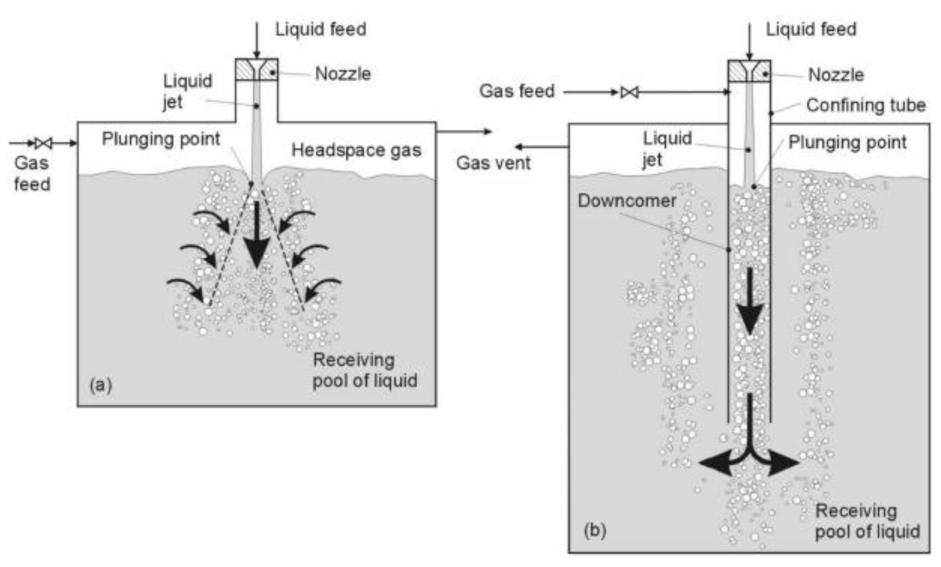
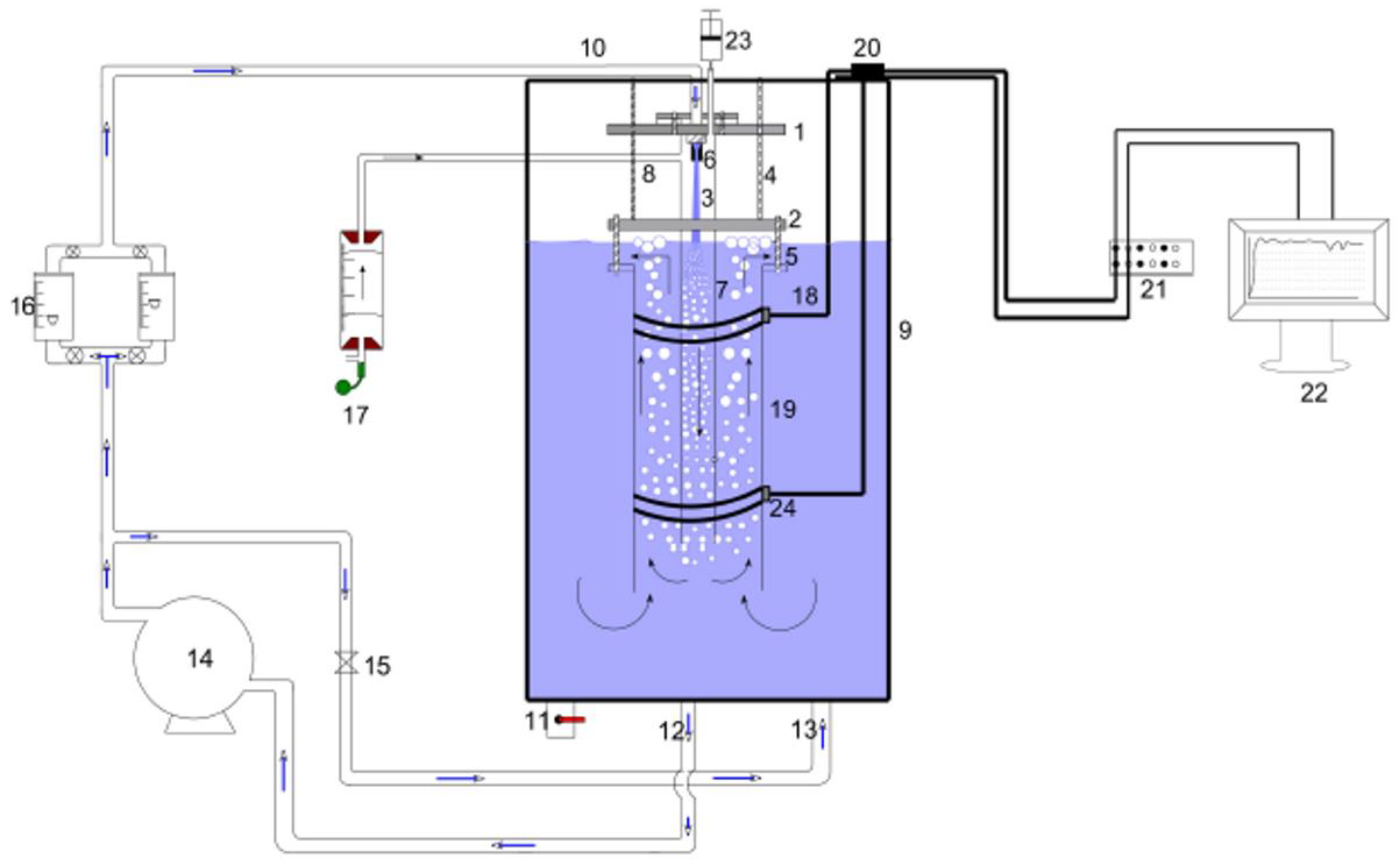
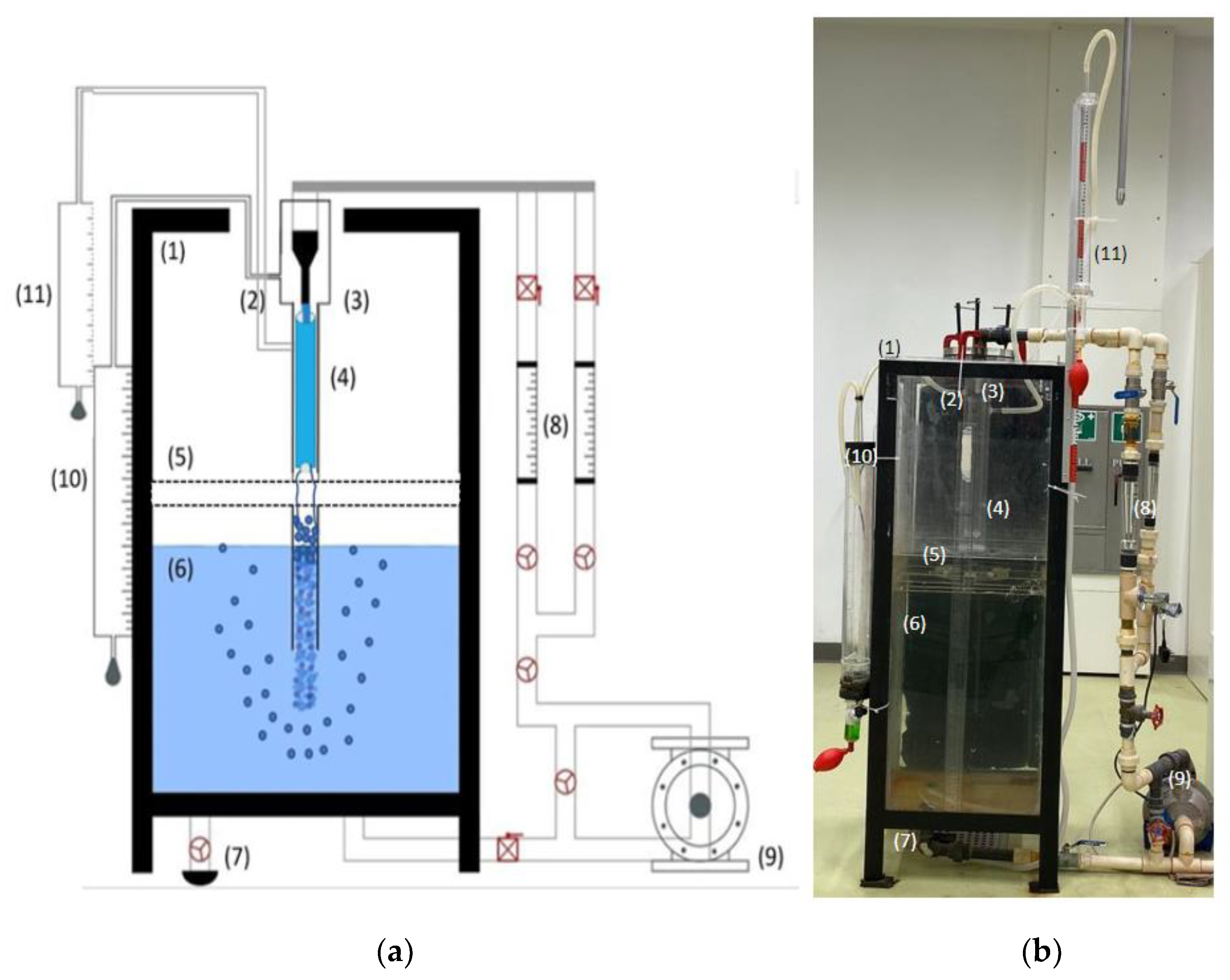
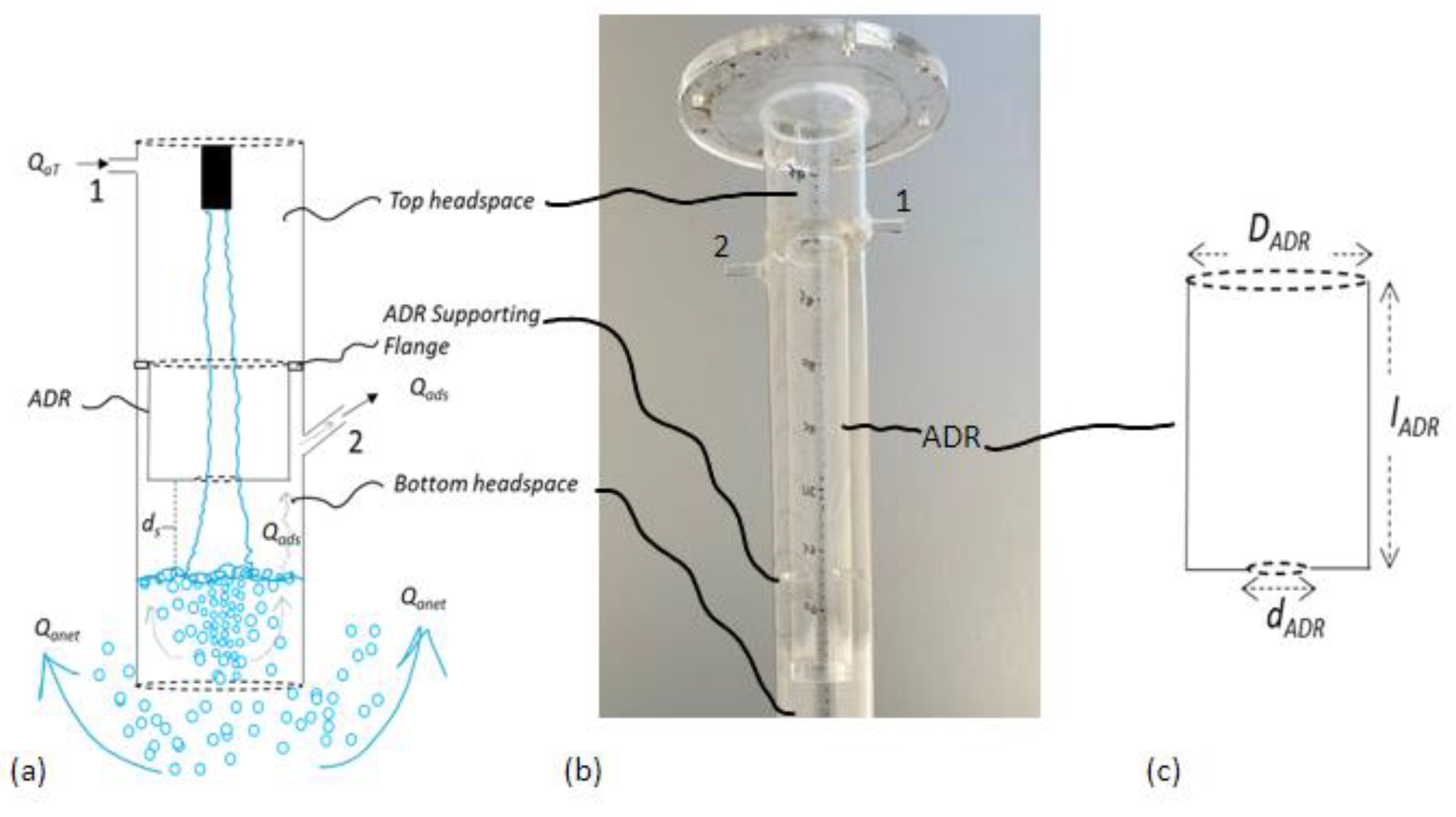
2.1. Confined Plunging Liquid Jet Reactor System

The CPLJR apparatus—similar to that used by the same author earlier—used to generate experimental results is shown in Figure 3 [4]. Water was withdrawn from the base of a reservoir (1.5 × 0.5 × 0.5 m3) by a centrifugal pump, to be recycled through rotameters and a nozzle located at the top of the same reservoir to form a water jet. Two rotameters were used to measure a maximum liquid flowrate of 60 LPM. The nozzle was designed with a length to diameter ratio of 5, according to Ohkawa et al. [24] and Al-Anzi et al. [23], and with a nozzle exit diameter (dn) of 8.1 mm. The nozzle was placed concentrically in the downcomer column, the diameter (Dc) of which was 7.4 cm, at Lj distances of 36–51 cm from the receiving water body.

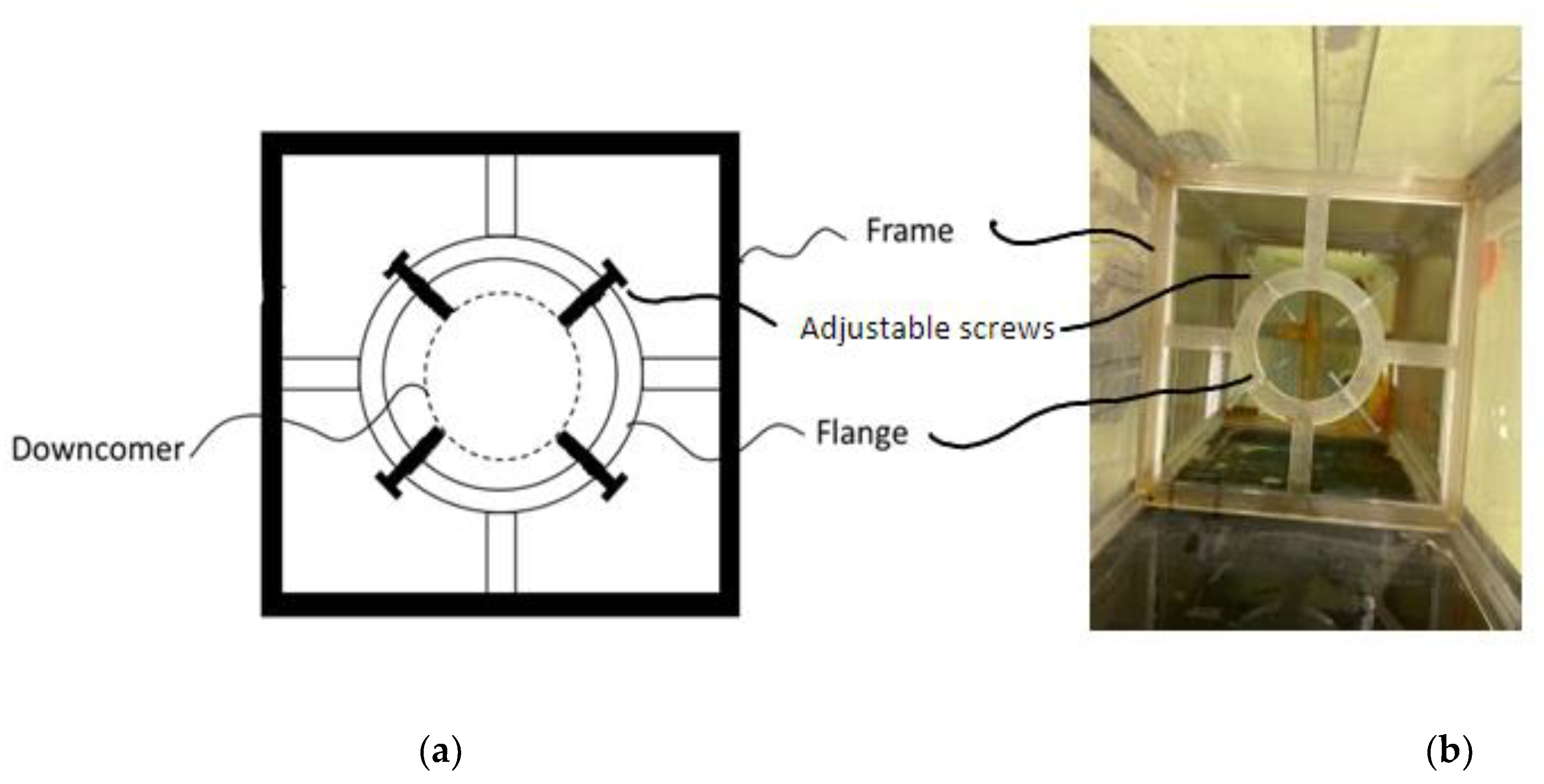
2.2. Supporting Flange/Frame

Figure 4 shows an extra external flange/frame with four adjustable screws that were spaced evenly in a radial manner. The external flange was fixed inside the tank and outside the downcomer to provide extra support for the downcomer with ADR device. The screws were adjustable; therefore, they can hold various downcomer diameters and lengths. The supporting frame/flange was rested on ledges mounted to the interior of the reservoir walls, which provided more stability to the entire system. This helped to eliminate any possible vibration and placed the nozzle concentrically inside the downcomer during the runs to ensure that the jet flowed directly into the center of the downcomer.

2.3. ADR Device

The other important device that was newly added to CPLJR apparatus was Al-Anzi’s disentrainment ring (ADR) device. It comprises a hollow cylindrical column with two diameters, one at each end; the larger diameter, DADR, is at the top, and the smaller one, dADR, is at the bottom. The two diameters are lADR apart; this figure represents the length of ADR device (Figure 5c). As shown in Figure 5b, ADR device is placed concentrically inside the CPLJR downcomer and is supported by two inner narrow ADR supporting flanges.
The purpose of the ADR device is to divide the downcomer into two headspaces (Figure 5a), top headspace above ADR and bottom headspace below ADR, which allow the initial entrained air from the top headspace to be released by the jet further down into the receiving pool below the ADR device. The released air will either leave the base of the downcomer as Qanet or ascend inside the downcomer as Qads. Qads will be prevented from escaping back to the top headspace by ADR device, so it can be collected in the bottom headspace below the ADR. Basically, ADR prevents Qads from ascending back into the top headspace. Qads will then leave the downcomer through tapping 2 to be measured by bubble meter 2. ADR is placed at a distance ds from the receiving water pool. Experiments were carried out with ds lengths of 0, 1, 3, 5 and 7.5 cm, and lADR of 34, 35, 37, 39 and 40 cm.

2.4. Downcomer (Confining Tube)

As shown in Figure 5, the novel downcomer differs from the original one by possessing the ADR device and two tappings. The top tapping is used to allow QaT to enter the system, measured by bubble meter 1, and the bottom tapping is used to allow Qads to leave the downcomer to be measured by bubble meter 2.
The measurements of QaT and Qads (volumetric air entrainment rate) were carried out as reported by Al-Anzi [4], i.e., using a soap bubble meter. Since soap bubbles provide negligible resistance to air flow, the bubble meter was the proper device for measuring both air entrainment and disentrainment flow rates. Soap bubble meters 1 and 2 comprise, respectively, a cylindrical tube with an inner diameter of 73 mm and a length of 1000 mm, and a cylindrical tube with an inner diameter of 36 mm and a length of 500 mm, to measure total and disentrainment rates, respectively. A solution of 10% household detergent, 5% glycerin and remaining water was used to prepare the soap bubble solution.

2.5. Calculation

The following assumption was made in deriving the QaT formulas: all the disentrained air leaves the downcomer through tapping 2 and does not escape through ADR back into the top headspace.
The PLJR downcomers are divided into standalone (original) and novel ADR downcomers. The addition of the novel ADR changed the mass balance around the two-phase flow mixture inside the downcomer, as described below:
1. Standalone/conventional downcomer:
Figure 6a shows a schematic of the standalone downcomer, including the control volume around the two-phase flow mixture inside the downcomer. Performing a mass balance around the selected control volume produces:
Q a T + Q a d s = Q a n e t + Q a d s
Qads in the case of the standalone downcomer will be re-entrained by the jet, reducing Equation (1) to Equation (2):
Q a T = Q a n e t
where the initial/total air entrainment rate, QaT, is equal to the net entrainment rate, Qanet (amount of the bubbles leaving the base of the downcomer).
At low jet velocities where no bubbles are leaving the base of the downcomer, QaT, in this case, is equal to zero, because Qanet = 0:
Q a T = Q a n e t = 0
2. Novel ADR downcomer:
The addition of the ADR device prevented Qads from being re-entrained by the jet (Figure 6b), and Equation (1) becomes:
Q a T = Q a n e t + Q a d s
At low jet velocities, Qanet = 0, Equation (4) is simplified to:
Q a T = Q a d s
At high jet velocities, when the bubbles leave the base of the downcomer, Equation (4) remains the same.

3. Results and Discussion

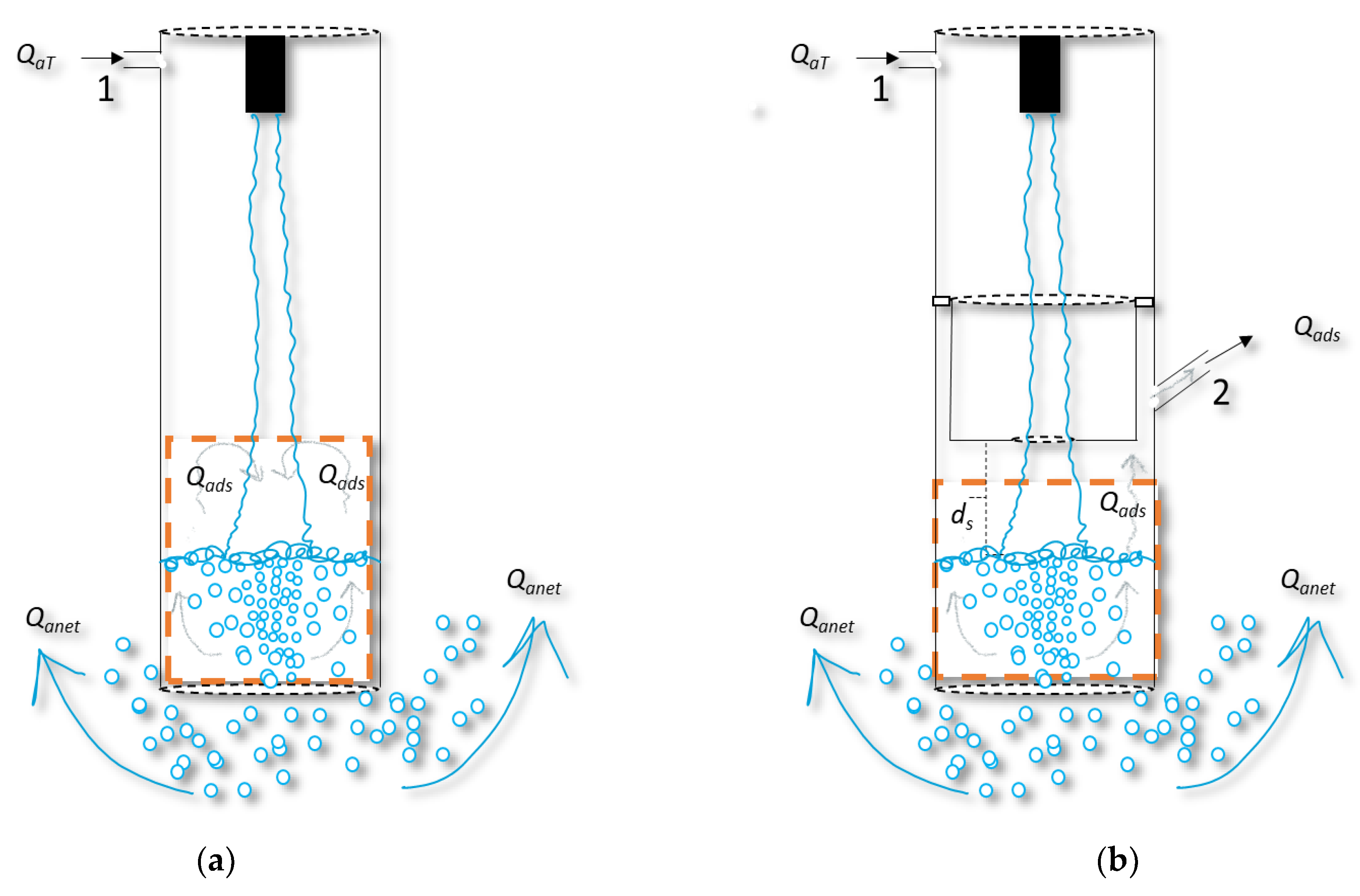
3.1. Effect of Distance between ADR Device and Receiving Pool Surface on the Air Entrainment and Disentrainment Rates

As shown in Figure 5a, ds is the distance between the end of the ADR device and the receiving pool’s surface. Figure 7 and Figure 8 show the effect of ds on QaT and Qads whilst keeping other main variables constant (Dc, Lj, dADR, Hc and lADR). The results obtained in this study show that QaT increases linearly with VL for all ds values with the shortest ds = 0 measuring the highest QaT values for all VL values. The high values recorded by the shortest distance, ds, could be attributed to the ADR hindering the formation of eddies that contributed in increasing Qads, as reported by Al-Anzi et al. [23]. As ds increased, another liquid jet is developed below the ADR that behaved in a similar manner to the original jet, which enhanced the Qads phenomenon in the second headspace (below the ADR). These results can be divided into two groups for VL values lesser and greater than VLnet ≈651 cm/s, where VLnet is the liquid jet velocity at the impingement point that is high enough to push the first bubble/bubbles out of the base of the downcomer to record the smallest Qanet. Group 1 represents measured QaT for VL values less than VLnet and group 2 includes QaT values generated by VL greater than VLnet. In group 2, the QaT values (shaded area) were higher than that of group 1, because QaT is equal to both Qads and Qanet; however, this was not the case for the set of results in group 1 where QaT is equal to Qads (no Qanet) for all of ds values.
However, the effect of ds on Qads was different from Qanet, particularly at higher VL (>VLnet), where Qads increased with VL until it reached maximum, and decreased thereafter (Figure 8). This is consistent for all ds values. The reason for the decrease of Qads at high VL was that the superficial velocity of the liquid in the downcomer was strong enough to carry most of entrained bubbles downwards out of the downcomer and, hence, the net entrainment rate (Qanet) increased at the cost of Qads.

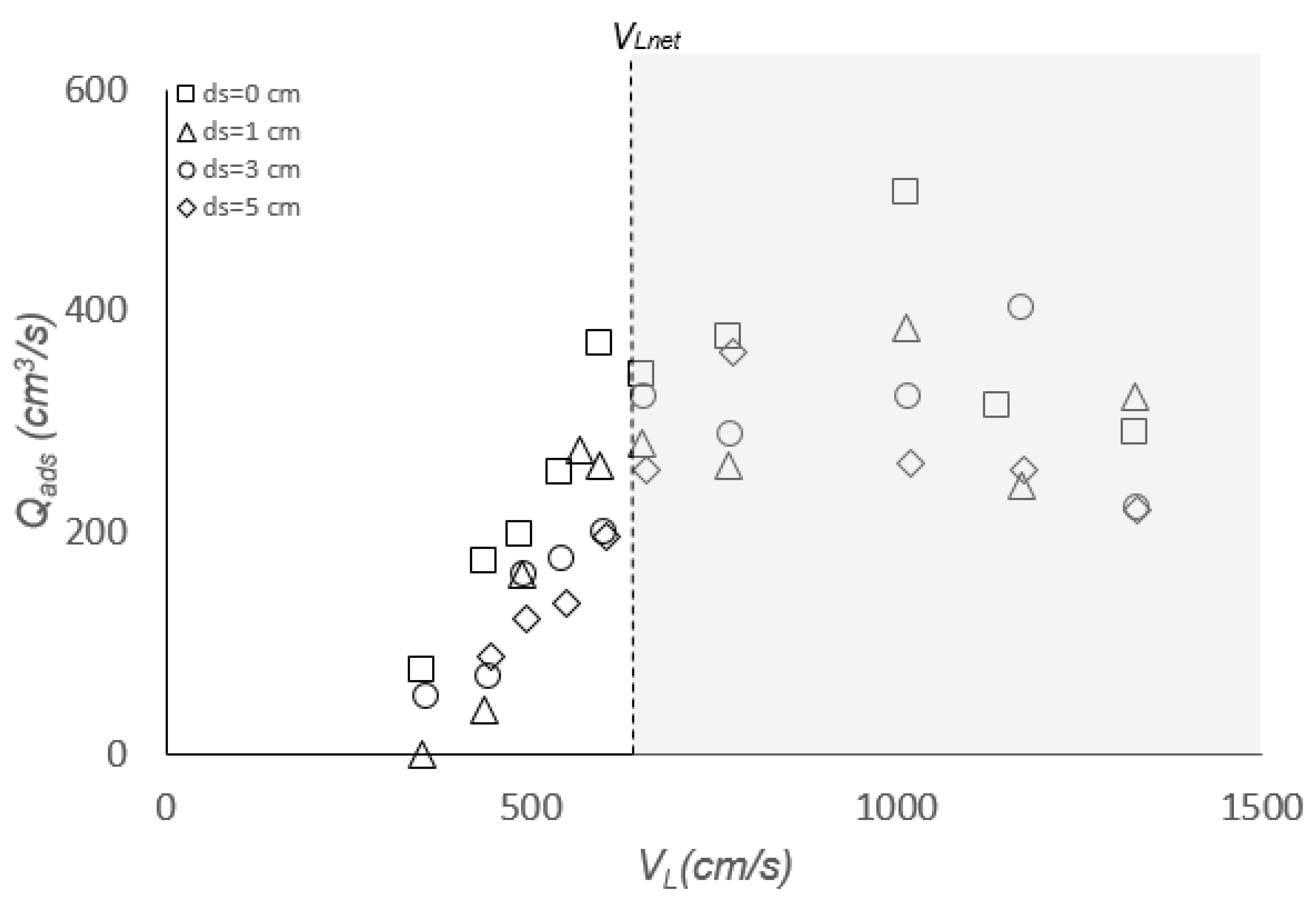
3.2. Effect of VL on Air Disentrainment and Entrainment Rate Measurements

Figure 9 shows four representative sets of data for an 8.1 mm nozzle diameter, 36–51 cm jet length and 74 mm downcomer diameter, corresponding to Hc of 43–46 cm. All sets of results showed 2 distinct regions of QaT for VL values lesser and greater than VLnet (651 cm/s) for all ds values. For VL less than VLnet, QaT = Qads because all of the entrained bubbles rose back inside the downcomer to be measured by disentrainment bubble meter 2. As VL increased further beyond VLnet, the liquid’s superficial velocity (momentum) was sufficient to push the bubbles downward out of the base of the downcomer to increase Qanet. This led to increased QaT in this region, since it is equal to the sum of both Qads and Qanet. These findings are important when designing CPLJR, because they determine when the system is efficient as an aerator and mixer, thus helping in designing an efficient and feasible system.

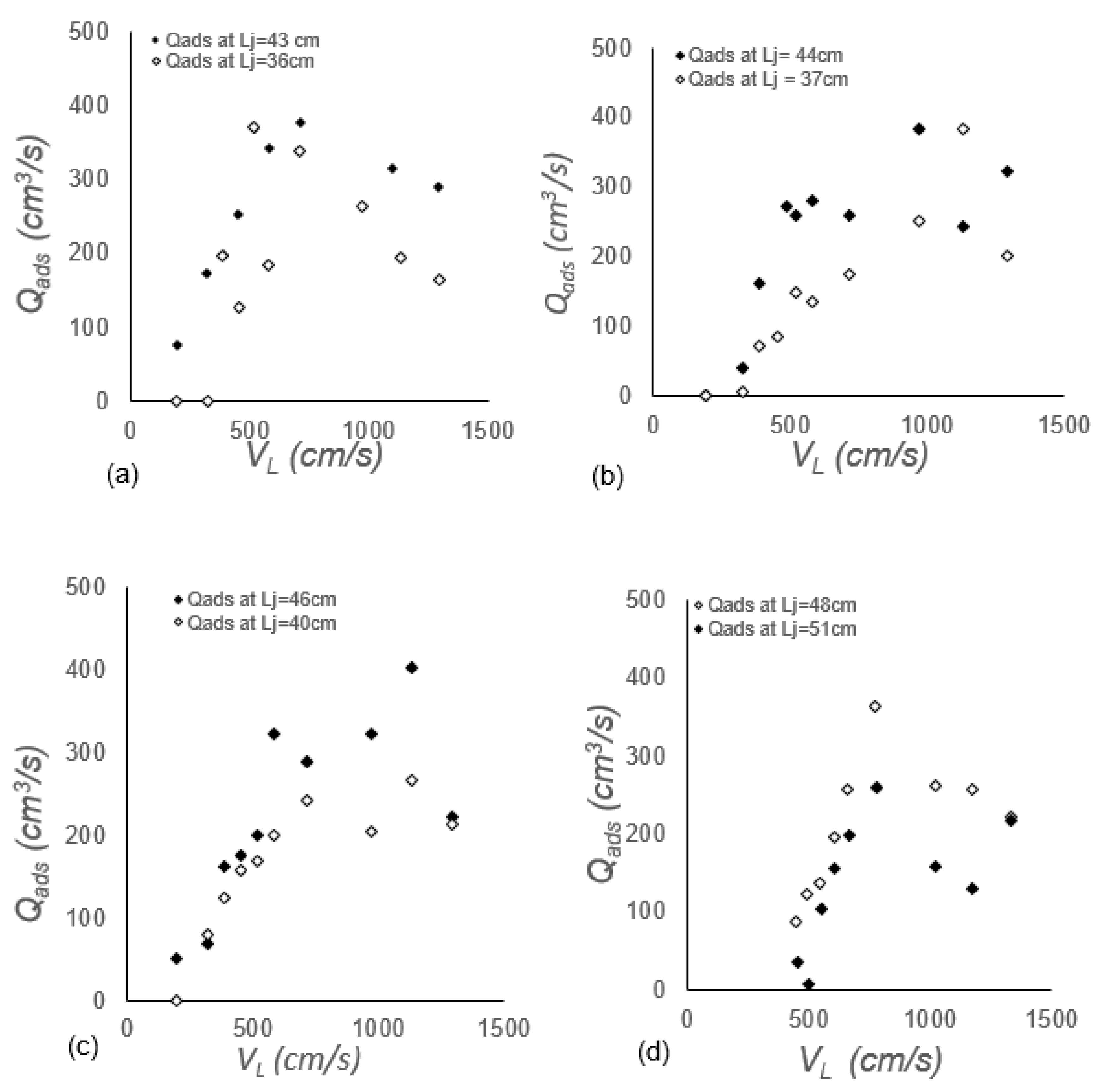
3.3. Effect of Jet Length on Air Disentrainment and Total Entrainment Rate Measurements

Lj is one of the important variables in PLJR systems and its effect on Qanet for a standalone downcomer has been investigated previously, by many authors, for confined and unconfined PLJR systems. Previous results in the literature showed that Qanet increases with Lj as long as the liquid jet is coherent and less than the break-up jet under the same operating conditions. This is because longer jets tend to increase the amplitude of disturbances on the surface of the rough jet [23] and increase the value of Vj to VL at the impingement point, since V L = V j 2 + 2 g L j , which is significant at low Vj [25]. The effect of Lj on Qads is depicted in Figure 10a–d for ds = 1–5 cm. All sets of data showed that Qads exhibited a similar trend as that described in the previous Section 3.2, with longer Lj measuring higher Qads, as expected. The current results confirmed the previous findings, in Section 3.2, of two distinct regions in each set of data at about VLnet (Qads increased for VL < VLnet and Qads decreased for VL > VLnet). Furthermore, the same results also showed that Qads is independent of ds (almost the same range of Qads for all ds).
QaT, however, increased linearly with Lj for all VL values. This increase is more evident in the second region (VL > VLnet), as shown by the sets of data plotted in Figure 11a–d. The effect of Lj on QaT in the current study is small because the difference between the two jets is small (∆Lj), with longer jets measuring slightly higher QaT.

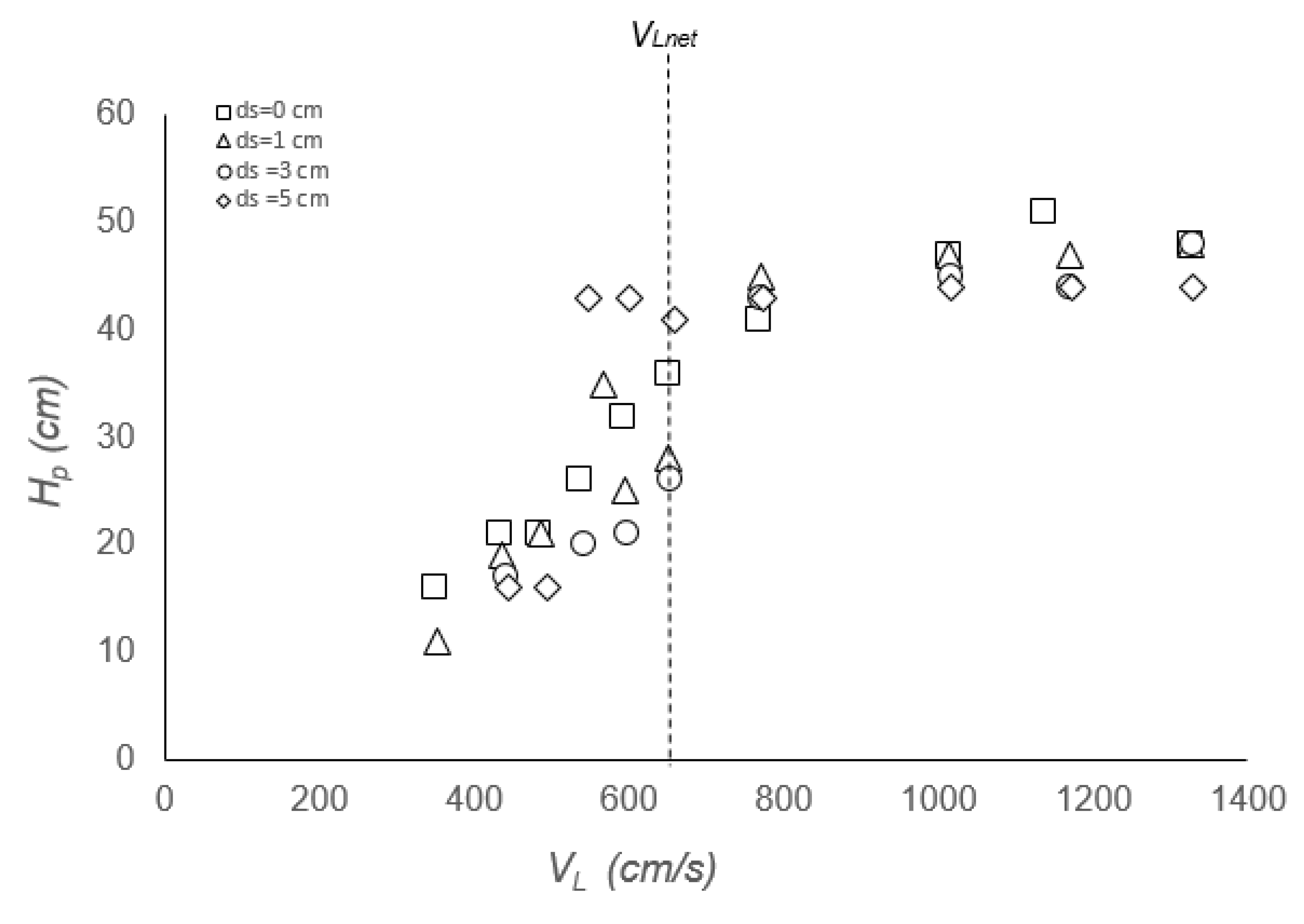
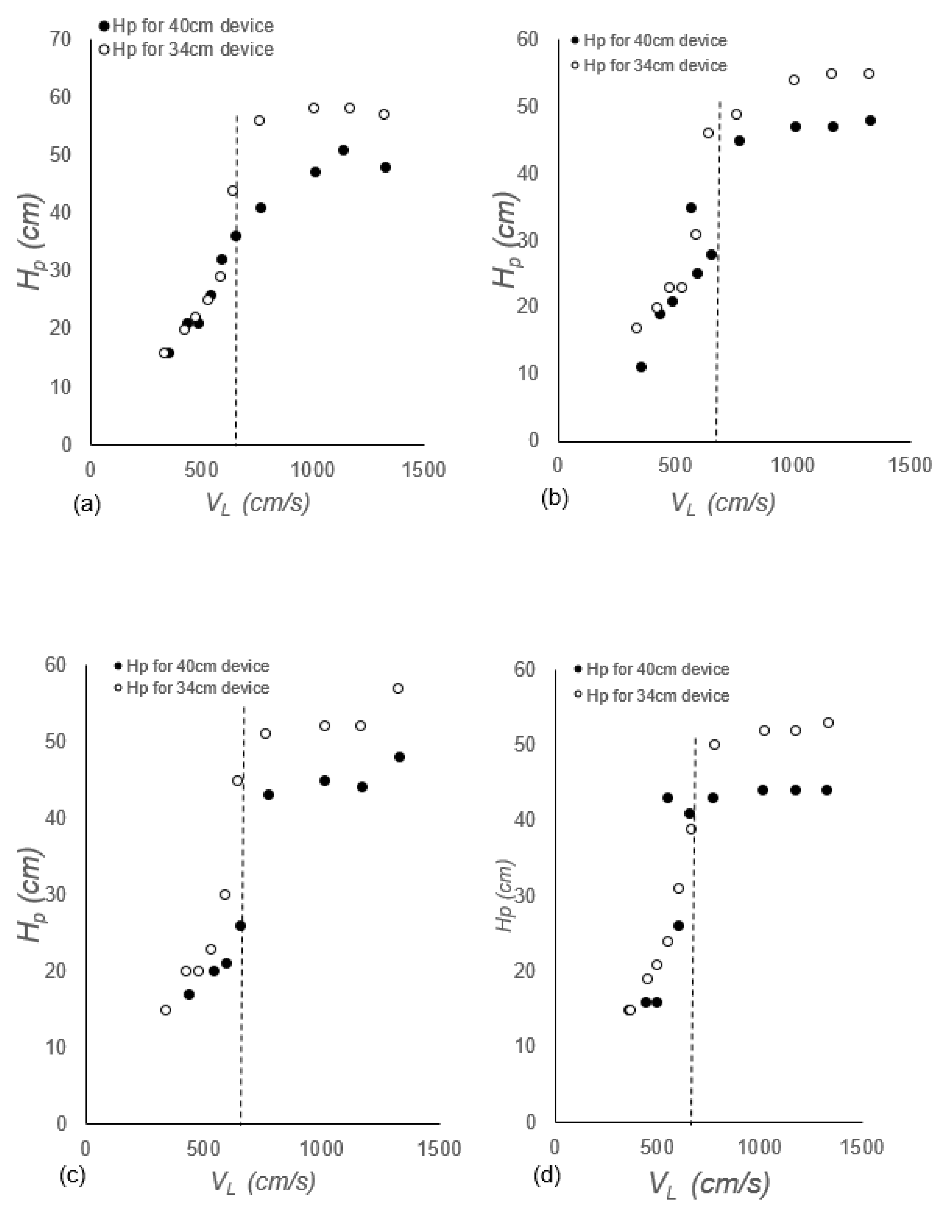
3.4. Effect of ds and lADR on Bubble Penetration Depths (Hp)

One of the aims of using confined plunging jets is achieving greater bubble penetration depth to augment dissolved oxygen (DO) and provide better mixing. Figure 12 showed that Hp increased linearly with a sharp slope in region 1 (VL < VLnet), whilst in region 2 (VL > VLnet), the penetration depth almost remained constant for the rest of VL values forming an “S” trend. The penetration depth, Hp, decreased with ds. This is because short ds hinders the formation of recirculating eddies responsible for the enhancement of Qads; thus, Qads is reduced, forcing most of the bubbles to leave the base of the downcomer as Qanet. This, in turn, led to greater bubble penetration depths. This is under the assumption that there is no momentum loss by the jet, for all ds values, as it passes through the ADR device.
The effect of two ADR devices (lADR = 34 and 40 cm) on Hp, for all ds values, has also been investigated in this study. The results are plotted in Figure 13a–d. One can clearly see the “S” trend displayed consistently in all figures for the two lADR values and four ds values (0, 1, 3 and 5 cm). This confirms the “S” shape, as discussed in the previous section (Figure 12). The effect of lADR is negligible at low jet velocity (region 1), particularly for short ds values; however, at high VL (region 2), the difference became visible, with higher Hp obtained for longer lADR. Again, higher lADR and ds values mean shorter Hc, and, thus, low Qads inside the downcomer. This meant that most of the bubbles left the base of the downcomer as Qanet and a small portion rose inside the downcomer as Qads, reducing the resistance of the counter current flow and achieving higher Hp.

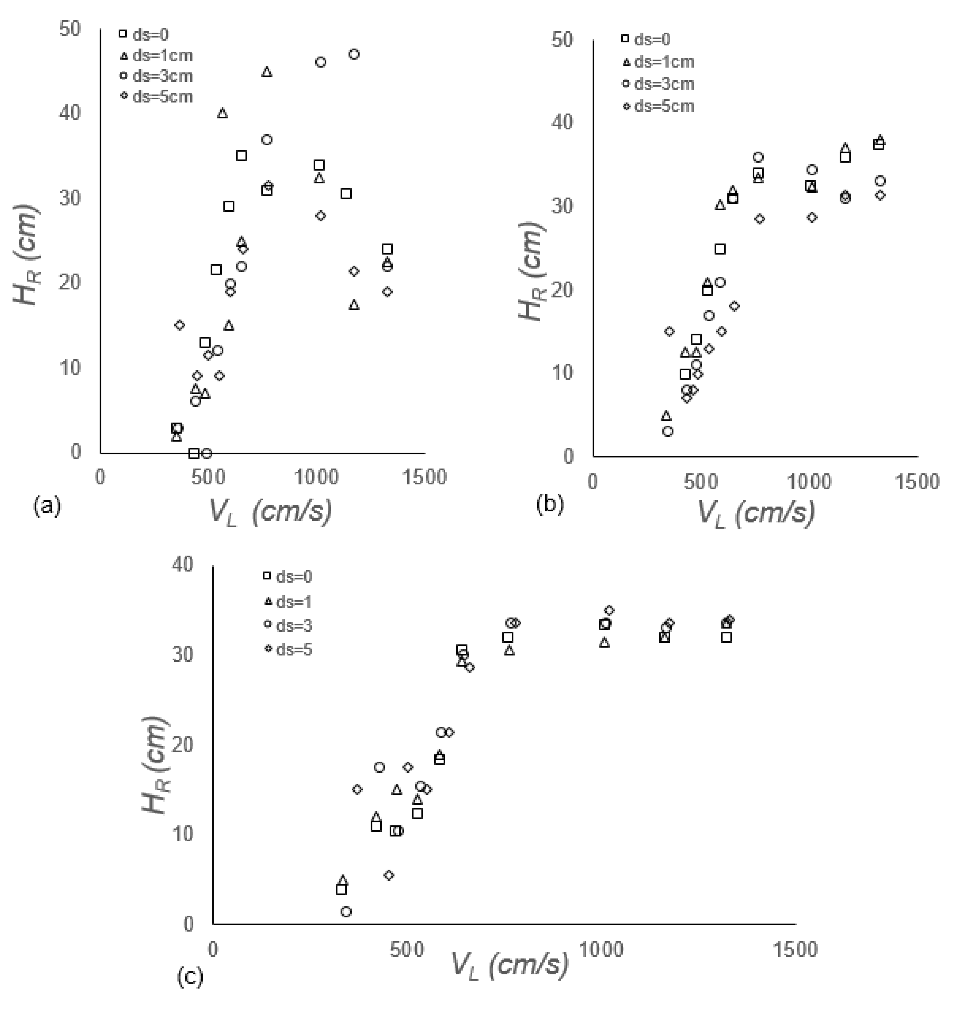
3.5. Effect of Rise Heights (HR) for ds Values

The HR trends corresponded to those of Hp, except for the longest lADR of 40 cm, where HR increased linearly until it reached a maximum and then decreased for all ds values. Decreasing HR is a good sign as it indicates that more bubbles are penetrating through the downcomer to leave as Qanet. The effect of ds on HR was small for the majority of the data (Figure 14a–c). It is still premature to fully understand the reason for such phenomena, since there were several factors/variables simultaneously contributing to the results. For example, high HR reduced the original Lj of the system which, in turn, reduced VL and, hence, the QaT. This affected the physics of the entire system. Having said that, we have made significant progress in understanding PLJR as an aerator and efficient mixer. Figure 15a–i is the actual impression of the novel ADR downcomers with lADR = 37 cm, showing HR and Hp levels for a range of ds and VL.

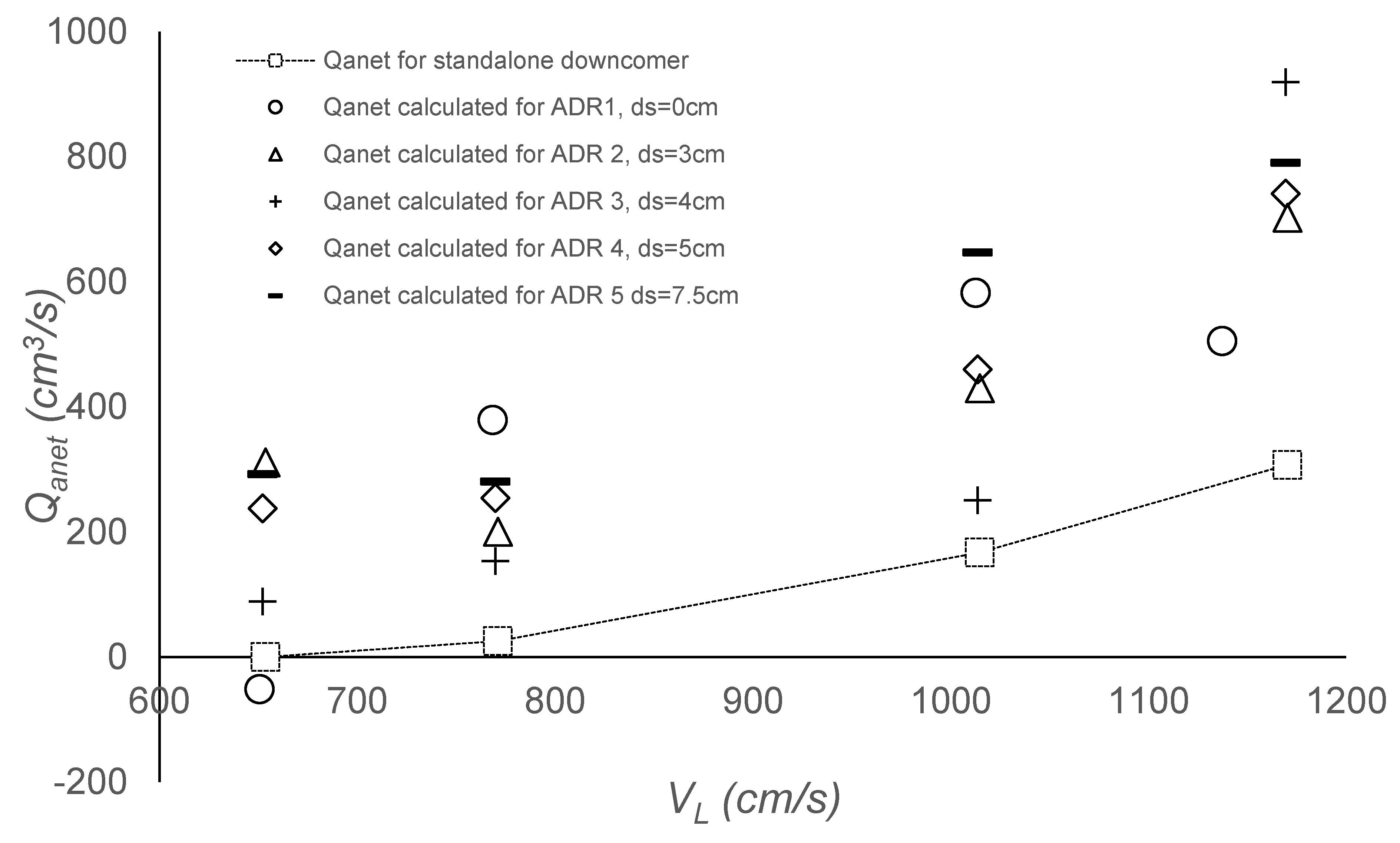
3.6. Comparison of the Effect of the Novel Downcomer (with ADR Device) and a Standalone Downcomer on Qanet

Figure 16 is generated to show the effect of the novel ADR downcomer and standalone downcomer on the Qanet. The same operating conditions were used for both downcomers (Dc = 7.4 cm, Lj = 45 cm, dn = 8.1 mm, Hc = 46 cm and lADR = 40 cm, 39 cm, 37 cm and 35 cm) throughout the experiments. Qanet for the standalone downcomer was measured experimentally by bubble meter 1, whereas Qanet for the novel ADR downcomer was estimated from Equation (4) by subtracting the experimental values of QaT from Qads measured by bubble meters 1 and 2, respectively. In total, five ds values from 0 to 7.5 cm were used for the ADR downcomer in this experiment. Both downcomers demonstrated increasing trends for Qanet, with VL that fit quadratic behavior: R2 ranged from 0.94–1.0. The results obtained consistently showed that the ADR device enhanced Qanet significantly for all ds values in comparison with the results of the standalone downcomer. It is noteworthy and interesting that the ADR device actually increased the Qanet significantly. For example, at low VL (654 cm/s, corresponding to the VLnet), Qanet increased from 0 for the standalone downcomer to a relative maximum of 477 cm3/s for the novel ADR downcomer with ds = 4 cm. At higher VL, Qanet increased by 2.5-fold, with ds = 5 cm (from 458 cm3/s for the standalone downcomer to an absolute maximum of 1143 cm3/s for the novel ADR downcomer). If it stands, this could be revolutionary in the field of CPLJR aeration. Clearly, more investigation under a wide range of operating conditions is required to confirm such important findings.

4. Conclusions

The current work is entirely novel from the perspective of idea generation, manufacturing, implementation and results. A novel ADR device with various dimensions was manufactured locally and successfully affixed inside CPLJR downcomers to measure air disentrainment rates experimentally and accurately, for the first time ever, for a range of new and old operating conditions. New variables came with the ADR, such as length of the ADR (lADR) and the distance (ds) of the ADR to the receiving pool. A new jet velocity value at the impingement point (VLnet) was defined as the minimum jet velocity for Qanet to be measured. The difference between QaT and Qads was negligible for VL < VLnet; however, this difference became substantial for VL > VLnet under the same operating conditions. Net air entrainment rate (Qanet) increased linearly with VL and Lj for all ds values, with the shortest ds (zero) measuring the highest Qanet; however, Qads exhibited different behavior for VL > VLnet, where it decreased after reaching an absolute maximum for all ds values. Bubble penetration depths (Hp) and liquid rise height (HR) increased for all VL until they reached maximum values and leveled off for the same lADR. Results also showed that shorter lADR produced higher Hp values; however, the measured HR values were lower under the same operating conditions.
One of the great contributions of this work is the substantial increase in Qanet measured by the novel ADR downcomer in comparison with the conventional standalone downcomer (2.5 to 15 times increase in Qanet), at no extra cost. This has been confirmed over a range of ds values (0 to 7.5 cm). Despite the significant progress we made in understanding PLJR as an aerator and efficient mixer, it is still premature to fully understand the reason for such phenomena since there were several factors/variables contributing to the results simultaneously. Thus, more studies under a wide range of operating conditions are required to confirm such important findings. This, in addition to the application of new primary variables and designs pertinent to the novel ADR device, will constitute the focus of our future work.

Author Contributions

Conceptualization, B.S.A.-A.; methodology, B.S.A.-A. and J.F.; resources, B.S.A.-A.; data curation, J.F.; writing—original draft preparation, J.F. and B.A; writing—review and editing, B.S.A.-A.; supervi-sion, B.S.A.-A. All authors have read and agreed to the published version of the manuscript.

Funding

This research was funded by Kuwait University, grant number FE 01/21.

Institutional Review Board Statement

Not applicable.

Informed Consent Statement

Not applicable.

Data Availability Statement

The data presented in this study are available on request from the corresponding author.

Conflicts of Interest

The authors declare no conflict of interest. The funders had no role in the design of the study; in the collection, analyses, or interpretation of data; in the writing of the manuscript, or in the decision to publish the results.

References

  1. Qu, X.; Khezzar, L.; Li, Z. The impact and air entrainment process of liquid plunging jets. Proc. Inst. Mech. Eng. Part E J. Process Mech. Eng. 2011, 226, 238–249. [Google Scholar] [CrossRef]
  2. Al-Anzi, B. Performance of a Novel Confined Plunging Jet Reactor Incorporating an Annular Airlift Column. Ph.D. Thesis, Loughborough University, Loughborough Leicestershire, UK, 2007. [Google Scholar]
  3. Kumar, M.; Tiwari, N.K.; Ranjan, S. Experimental study on oxygen mass transfer characteristics by plunging hollow jets. Arab. J. Sci. Eng. 2021, 46, 4521–4532. [Google Scholar] [CrossRef]
  4. Al-Anzi, B. Effect of primary variables on a confined plunging liquid jet reactor. Water 2020, 12, 764. [Google Scholar] [CrossRef] [Green Version]
  5. Chow, A.C.; Shrivastava, I.; Adams, E.E.; Al-Rabaie, F.; Al-Anzi, B.A. Unconfined dense plunging jets used for brine disposal from desalination plants. Processes 2020, 8, 696. [Google Scholar] [CrossRef]
  6. Shrivastava, I.; Adams, E.E.; Al-Anzi, B.; Chow, A.C.; Han, J. Confined plunging liquid jets for dilution of brine from desalination plants. Processes 2021, 9, 856. [Google Scholar] [CrossRef]
  7. Cummings, P.D.; Chanson, H. Air entrainment in the developing flow region on plunging jets—Part 1: Theoretical development. J. Fluids Eng. 1997, 119, 597–602. [Google Scholar] [CrossRef] [Green Version]
  8. Qu, X.L.; Danciu, D.; Labois, M.; Lakehal, D. Characterization of plunging liquid jets: A combined experimental and numerical investigation. Int. J. Multiph. Flow 2011, 37, 722–731. [Google Scholar] [CrossRef]
  9. Miwa, S.; Moribe, T.; Tsutstumi, K.; Hibiki, T. Experimental investigation of air entrainment by vertical plunging liquid jet. Chem. Eng. Sci. 2018, 181, 251–263. [Google Scholar] [CrossRef]
  10. Bin, A.K. Gas entrainment by plunging jets. Chem. Eng. Sci. 1993, 48, 3585–3630. [Google Scholar] [CrossRef]
  11. Kramer, M.; Wieprecht, S.; Terheiden, K. Penetration depth of plunging liquid jets- A data driven modelling approach. Exp. Therm. Fluid Sci. 2016, 76, 109–117. [Google Scholar] [CrossRef] [Green Version]
  12. Harby, K.; Chiva, S.; Muñoz-Cobo, J.L. An experimental study on bubble entrainment and flow characteristics of vertical plunging water jets. Exp. Therm. Fluid Sci. 2014, 57, 207–220. [Google Scholar] [CrossRef]
  13. Cummings, P.D.; Chanson, H. An experimental study of individual air bubble entrainment at a planar plunging jet. Chem. Eng. Res. Des. 1999, 77, 159–164. [Google Scholar] [CrossRef] [Green Version]
  14. Warjito; Budiarso; Pramono, I.A.; Samosir, M.L.; Adanta, D. The effect of jet height in air entrainment process of vertical plunging jet with downcomer. AIP Conf. Proc. 2018, 2062, 020023. [Google Scholar] [CrossRef]
  15. McKeogh, E.J.; Ervine, D.A. Air entrainment and diffusion pattern of plunging liquid jets. Chem. Eng. Sci. 1981, 36, 1161–1172. [Google Scholar] [CrossRef]
  16. Schmidtke, M.; Danciu, D.; Lucas, D. Air entrainment by impinging jets experimental identification of the key phenomena and approaches for their simulation in CFD. In Proceedings of the 17th International Conference on Nuclear Engineering (ICONE17), Brussels, Belgium, 12–16 July 2009; paper no. ICONE17-75293. pp. 297–305. [Google Scholar]
  17. Lahey, R.T., Jr. On the direct numerical simulation of two-phase flow. Nucl. Eng. Des. 2009, 239, 867–879. [Google Scholar] [CrossRef]
  18. Galimov, A.Y.; Sahni, O.; Lahey, R.T.; Shephard, M.S.; Drew, D.A.; Jansen, K.E. Parallel adaptive simulation of a plunging liquid jet. Acta Math. Sci. 2010, 30, 522–538. [Google Scholar] [CrossRef]
  19. Brouilliot, D.; Lubin, P. Numerical simulations of air entrainment in a plunging jet of liquid. J. Fluids Struct. 2013, 3, 428–440. [Google Scholar] [CrossRef]
  20. Boualouache, A.; Zidouni, F.; Mataoui, A. Numerical Visualization of Plunging Water Jet using Volume of Fluid Model. J. Appl. Fluid Mech. 2018, 11, 95–105. [Google Scholar] [CrossRef]
  21. Clark, N.N.; Flemmer, R.L. Predicting the holdup in two-phase bubble upflow and downflow using the Zuber and Findlay drift-flux model. AIChE J. 1985, 31, 500–503. [Google Scholar] [CrossRef]
  22. Al-Anzi, B. Apparatus for Measuring Disentrainment Rate of Air. US. Patent No. 2020/0103324, 2 April 2020. U.S. Patent and Trademark Office. [Google Scholar]
  23. Al-Anzi, B.; Cumming, I.W.; Rielly, C.D. Air entrainment rates in a confined plunging jet reactor. In Proceedings of the 10th International Conference on Multiphase Flow in Industrial Plants, Tropea, Italy, 20–23 September 2006; pp. 71–82. [Google Scholar]
  24. Ohkawa, A.; Kusabiraki, D.; Kawai, Y.; Sakai, N. Some flow characteristics of a vertical liquid jet system having downcomers. Chem. Eng. Sci. 1986, 41, 2347–2361. [Google Scholar] [CrossRef]
  25. Al-Anzi, B.S.; Fernandes, J. Sensitivity Test of Jet Velocity and Void Fraction on the Prediction of Rise Height and Performance of a Confined Plunging Liquid Jet Reactor. Processes 2022, 10, 160. [Google Scholar] [CrossRef]
Figure 1. (a) An unconfined plunging liquid jet reactor system (PLJR), (b) a confined plunging liquid jet reactor system (CPLJR) [2].
Water 15 00835 g001
Figure 2. Schematic diagram of the air-lift column in the confined plunging liquid jet reactor: (1) top flange, (2) bottom flange, (3) liquid jet, (4) supporting rods, (5) riser rods, (6) nozzle, (7) downcomer, (8) air tapping, (9) water tank, (10) water supply, (11) drain, (12) recycled water, (13) bypass, (14) pump, (15) valve, (16) rotameter, (17) bubble meter, (18) wires, (19) annulus, (20) connection point, (21) amplifier, (22) PC, (23) injecting salt by syringes, (24) electrodes [2,4].
Water 15 00835 g002
Figure 3. (a) The upgraded CPLJR apparatus with two bubble meters for measuring both entrainment and disentrainment rate: (1) tank, (2) tapping, (3) nozzle, (4) ADR, (5) supporting flange/frame, (6) receiving pool, (7) drainage outlet, (8) rotameters, (9) pump, (10) bubble meter 1, (11) bubble meter 2, (b) picture of the upgraded CPLJR apparatus in the laboratory in College of Life Sciences, Kuwait University.
Water 15 00835 g003
Figure 4. (a) Design of the supporting flange/frame that holds the downcomer in position; (b) top view of the CPLJR unit showing the supporting flange and other parts (adjustable screws, frame and flange).
Water 15 00835 g004
Figure 5. (a) Design of the novel ADR downcomer showing the ADR device. (b) Front view of the novel ADR downcomer showing the ADR device and other parts (ADR supporting flange, tapping 1 and tapping 2. (c) Design of the ADR device with dimensions.
Water 15 00835 g005
Figure 6. Schematic of the (a) standalone downcomer and (b) novel ADR downcomer including the control volume around the two-phase flow mixture inside the downcomer.
Water 15 00835 g006
Figure 7. Total entrainment flow rates as ds increases from 0 to 5 cm for lADR = 40 cm.
Water 15 00835 g007
Figure 8. Disentrainment flow rates as ds increases from 0 to 5 cm for lADR = 40 cm.
Water 15 00835 g008
Figure 9. Total air entrainment and disentrainment flow rates for (a) ds = 0, Lj = 43 cm, Hc = 46 cm; (b) ds = 1, Lj = 44 cm, Hc = 45 cm; (c) ds = 3, Lj = 46 cm, Hc = 43 cm; and (d) ds = 5, Lj = 48 cm, Hc = 43 cm for downcomer with lADR = 40 cm.
Water 15 00835 g009
Figure 10. Disentrainment rates over wide range of Vj and Lj = 36–51 cm for ds = (a) 0 cm, (b) 1 cm, (c) 3 cm and (d) 5 cm.
Water 15 00835 g010
Figure 11. Total air entrainment rates for varying VL at different Ljs for (a) ds = 0, Lj = 43 cm and 46 cm; (b) ds = 1, Lj = 44 cm and 37 cm; (c) ds = 3, Lj = 46 cm and 40 cm; and (d) ds = 5, Lj = 48 cm and 43 cm.
Water 15 00835 g011
Figure 12. Effect of penetration depth as flowrate increases for different ds spacing for lADR = 40 cm.
Water 15 00835 g012
Figure 13. Effect of Hp for varying VL for different smart devices of length 40 and 34 cm at (a) ds = 0 (b) ds = 1, (c) ds = 3, (d) ds = 5.
Water 15 00835 g013
Figure 14. Rise height recorded at different ds levels for a range of jet velocities for ADR device of length (a) 40 cm, (b) 37 cm, and (c) 34 cm.
Water 15 00835 g014
Figure 15. Hp and HR levels in a downcomer of lADR = 37 cm and ds = 1 cm (ac); ds = 3 (df); and ds = 5 (gi).
Water 15 00835 g015
Figure 16. The effect of standalone downcomer vs. novel ADR downcomer on Qanet for CPLJR with Dc = 7.4 cm, Lj = 45 cm, Hc = 46 cm and dn = 8.1 mm.
Water 15 00835 g016
Disclaimer/Publisher’s Note: The statements, opinions and data contained in all publications are solely those of the individual author(s) and contributor(s) and not of MDPI and/or the editor(s). MDPI and/or the editor(s) disclaim responsibility for any injury to people or property resulting from any ideas, methods, instructions or products referred to in the content.

