
Numerical Simulation of Drilling Fluid Flow in Centrifugal Pumps

1
National-Provincial Joint Engineering Laboratory for Fluid Transmission System Technology, Zhejiang Sci-Tech University, Hangzhou 310018, China
2
School of Mechanical Engineering, Zhejiang Sci-Tech University, Hangzhou 310018, China
*
Author to whom correspondence should be addressed.
Water 2023, 15(5), 992; https://doi.org/10.3390/w15050992
Submission received: 3 February 2023
/
Revised: 20 February 2023
/
Accepted: 3 March 2023
/
Published: 5 March 2023
(This article belongs to the Topic Computational Fluid Dynamics (CFD) and Its Applications)
Abstract
:Centrifugal pumps are widely used in the oil and mining industries. In contrast to water pumps, the centrifugal pumps in the oil and mining industries are used for the transportation of drilling fluid, which is typically non-Newtonian fluid. Drilling fluids are usually modeled as power-law fluids with varying shear viscosity and imposed shear rates. In this paper, a numerical simulation of power-law fluid flow in a centrifugal pump was simulated, varying only in the flow-rate magnitude, using water flow as a comparison. The simulation results show that the pump used for drilling fluid presents a lower head and efficiency but a higher shaft power than that used for water. The flow patterns of both the water pump and the drilling fluid pump were investigated in terms of pressure fluctuation, turbulent kinetic energy, and radial force on the impeller. In contrast to the literature, this paper also analyzes the pressure pulsations in the individual blades of the impeller, as well as those in the volute path. In the case of drilling fluid, it was found that the viscous effect made the flow at the end of the blades highly irregular, and this could be attributed to the pressure generated by them. At the same time, the fluid flow at the small cross-section of the volute was more sensitive to the rotation of the impeller. In addition, the effects of the shear collision exerted on the outlet fluid of the impeller and the fluid in the volute, as well as the dynamic and static interferences, made the non-Newtonian power-law fluid consume more mechanical energy than the water. The results of this paper can be used as a reference for improving the design of centrifugal pumps using non-Newtonian fluids as media.
1. Introduction
Centrifugal pumps are widely used in the mechanical, chemical, energy, civil construction, aerospace, and other sectors of the national economy as a large and diverse range of general machinery [1,2,3,4,5]. Both experimental and computational fluid dynamics (CFD) methods can be used to evaluate the performance of the pumps. The internal flow of an impeller pump has been numerically simulated, and the results have been previously reported. The simulation method has a clear advantage over experimental methods in this regard [6]. In many branches of research and engineering, there is a great deal of interest in understanding the characteristics of non-Newtonian fluid flow [7]. When handling liquids that are more viscous than water, the performance of a centrifugal pump is affected.
The flow field analysis of non-Newtonian fluids in centrifugal pumps has made significant strides with advancements in the computational fluid dynamics (CFD) technique. For instance, researchers have studied the non-Newtonian behavior of blood using the Casson and power-law relations for the fluid model. The data on dynamic viscosity were fit using experimental data. The results were compared to those obtained for the Newtonian fluid flow in a mixed-flow blood pump [8]. Some researchers have proposed improvements to the method of auditing the heads of hydraulic bodies for all homogeneous non-Newtonian fluids [9,10,11,12]. There have also been advances in research into the effects of the structural design of centrifugal pumps on the internal flow field. Ma et al. [13] studied the performance of a centrifugal pump used in medium consistency technology (MC technology). In the design of an MC pump, the blade height cannot be too small because sufficient operation clearance is needed. The higher the concentration, the larger the tip clearance needed. Zhou et al. [14] discussed changes in fluid-induced force with impeller eccentricity, and the unsteady flow characteristics of the internal flow field of a centrifugal pump under different flow conditions and rotation speeds were investigated, as was the relationship between the fluid-induced force of the impeller and the internal flow field characteristics. Xuan et al. [15] reported that the steady-state flow characteristics of non-Newtonian power-law fluids and water differed significantly. Aldi et al. [16] presented results obtained by experimentally studying non-Newtonian fluids using small centrifugal pumps to highlight the performance differences between non-Newtonian fluids and water [17,18]. The rheological behavior of non-Newtonian fluids was experimentally analyzed with a rotational rheometer. It was found that at low flow rates, the performance of the pump tended to change significantly when the viscosity of the non-Newtonian fluid was different. Mrinal et al. [19] investigated PR models that could predict head and efficiency as a function of flow rate, velocity, and slurry viscosity by comparing the effects of non-Newtonian fluids of different viscosities in a centrifugal pump. Valdés et al. [20] conducted an analysis of non-Newtonian fluids’ handling of rheology, similar to that of in situ mixtures, and compared their performances when working with Newtonian viscous fluids. Donmez et al. [21] examined non-Newtonian fluids in centrifugal pumps using experiments and circulating hydrodynamics. The results indicate that the non-Newtonian fluid pump outperformed the water pump at 3300 rpm, while the opposite was found at 1400 rpm. Abdolahnejad et al. [22] estimated the calculation of slip factors in Newtonian and non-Newtonian slurries using CFD software and found that different viscosity fluids affected pump performance differently because of the inverse effects of particle settling velocity and friction loss versus viscosity change. Achour et al. [23] found that the flow topology in a pump is directly related to the viscosity property of a non-Newtonian fluid. The viscosity property governs pump performance by influencing the loss mechanisms that occur within a pump. However, they failed to provide a detailed analysis of the internal performance of the centrifugal pump and the resulting effects on the impeller as the viscosity varied.
Although there is a large body of research on fluid flow between a rotating impeller and a stationary volute, there is a lack of research relating the forces on an impeller and volute to the vortex flow in centrifugal pumps in the complex of vortices, particularly for non-Newtonian fluids. The aim of this paper is to investigate the results of single-phase power-law fluids acting on impellers and volutes in centrifugal pumps. The results were compared with those of water flow, and the non-Newtonian effects of the fluids on the centrifugal pumps are investigated and explained. In order to achieve this, we used ANSYS Fluent 2020R2 software as the simulation software, Tecplot360 2021R1 software as the image-processing software, and Origin 2019b software as the graph-processing software for the processing analysis. This paper focuses on the pressure pulsations in the separate blades of the impeller and those in the volute path, showing that the power-law fluid became less detached from the flow at the blade as the flow rate increased and that the vortices were generated at the impeller inlet. The fluid flow at the small cross-section of the volute was also more sensitive to the rotation of the impeller. These results bring new insights into the handling of highly viscous power-law fluids flowing in centrifugal pumps. They may help validate numerical simulations and improve the design of new impellers suitable for the flow of highly viscous fluids, among other applications.
2. Mathematical Models
The internal flow associated with a centrifugal pump can be considered unsteady incompressible three-dimensional turbulent flow without considering heat transfer [5], and the governing equations follow the conservation laws of mass and momentum. In particular, the law of mass conservation can be expressed as:
and the law of momentum conservation is:
where is the fluid density, is the fluid viscosity, is the velocity in the i direction, and is the source term. The finite volume method is applied for the numerical solution to the above equations. For the discretization of the above momentum equations, the second-order upwind scheme is applied to the spatial discretization of the convection term, and the center differential scheme with second-order accuracy is applied to the spatial discretization of the diffusion term. The SIMPLE algorithm is used for the coupling of the velocity and pressure calculations.
2.1. Non-Newtonian Fluid Models
The power-law fluid model is one of the most widely used non-Newtonian fluid models in engineering, and it applies to both pseudoplastic and expansive fluids. For non-Newtonian fluid, the viscosity µ in Equation (2) is often referred to as the apparent viscosity, and its value depends not only on the fluid itself but also on the flow state of the fluid [15]. The constitutive relation of power-law fluid can be expressed as follows:
where K is the consistency coefficient that depends on the nature of the fluid with the dimension of , is the shear rate, and n is the dimensionless flow index. The magnitude of the index characterizes the extent to which the rheology of the fluid deviates from that of Newtonian fluid. For Newtonian fluids, n = 1; for pseudoplastic fluids, n < 1; and for expansive fluids, n > 1. For drilling fluids, the magnitude of n is generally less than 1, which includes the so-called pseudoplastic fluids. According to the literature [24], we selected one of the classical drilling fluids as a reference for the current simulation, where K = 0.7815, n = 0.5268, and = 1490 kg/m3.
2.2. Turbulent Models
In this study, the shear-stress transport (SST) k-ω turbulence model was used, and the governing equations of turbulent kinetic energy and dissipation are as follows [25]:
and
where the blending function is defined by:
with , and y is the distance to the nearest wall.
The turbulent eddy viscosity is defined as follows:
where S is the invariant measure of the strain rate and is a second blending function defined by:
P is a production term such that:
where is the model constant and is the turbulence scale. The magnitudes of these constants are set as and , which have also been adopted in the literature [25].
3. Model Description
3.1. Computational Domain and Meshing
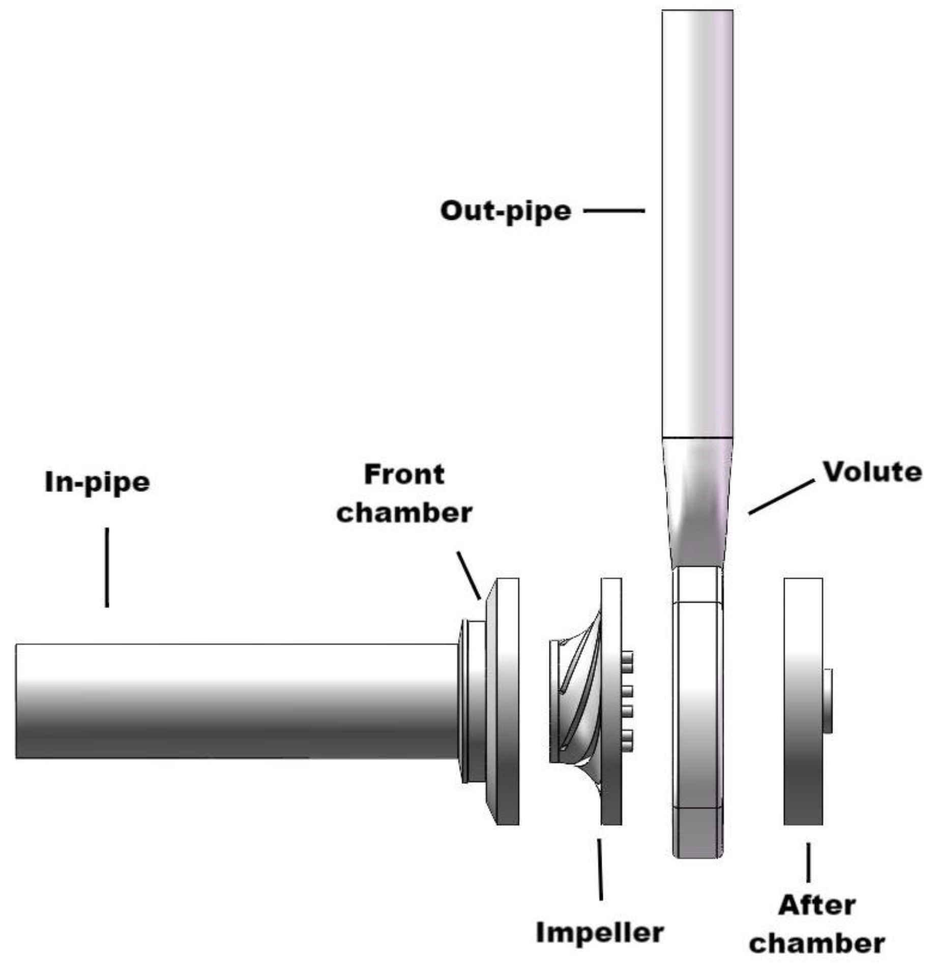
Figure 1 shows a schematic diagram of the simulation fluid domain in the pump. The pump is surrounded by the inlet and rear pump cavity walls, the volute walls, and the outlet flow channel walls. The velocity inlet and pressure outlet boundary conditions are employed, respectively. The contact surface of each part inside the pump is the interface model. The walls of the blades (that follow the rotation of the impeller) at the front and rear covers of the impeller are set as static walls. The no-slip boundary conditions are adopted on the solid walls. The nearest wall adopts the standard wall function. The main parameters are shown in Table 1.
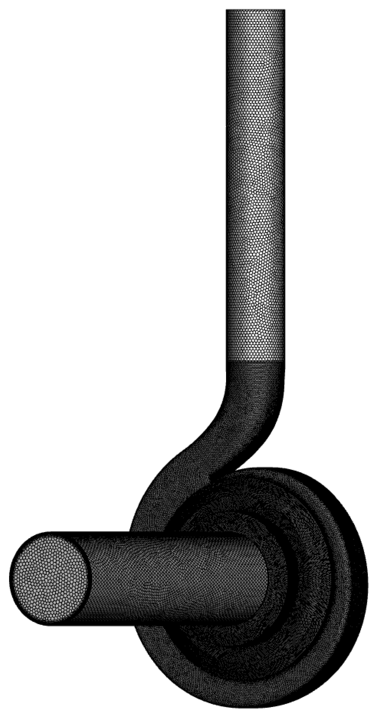
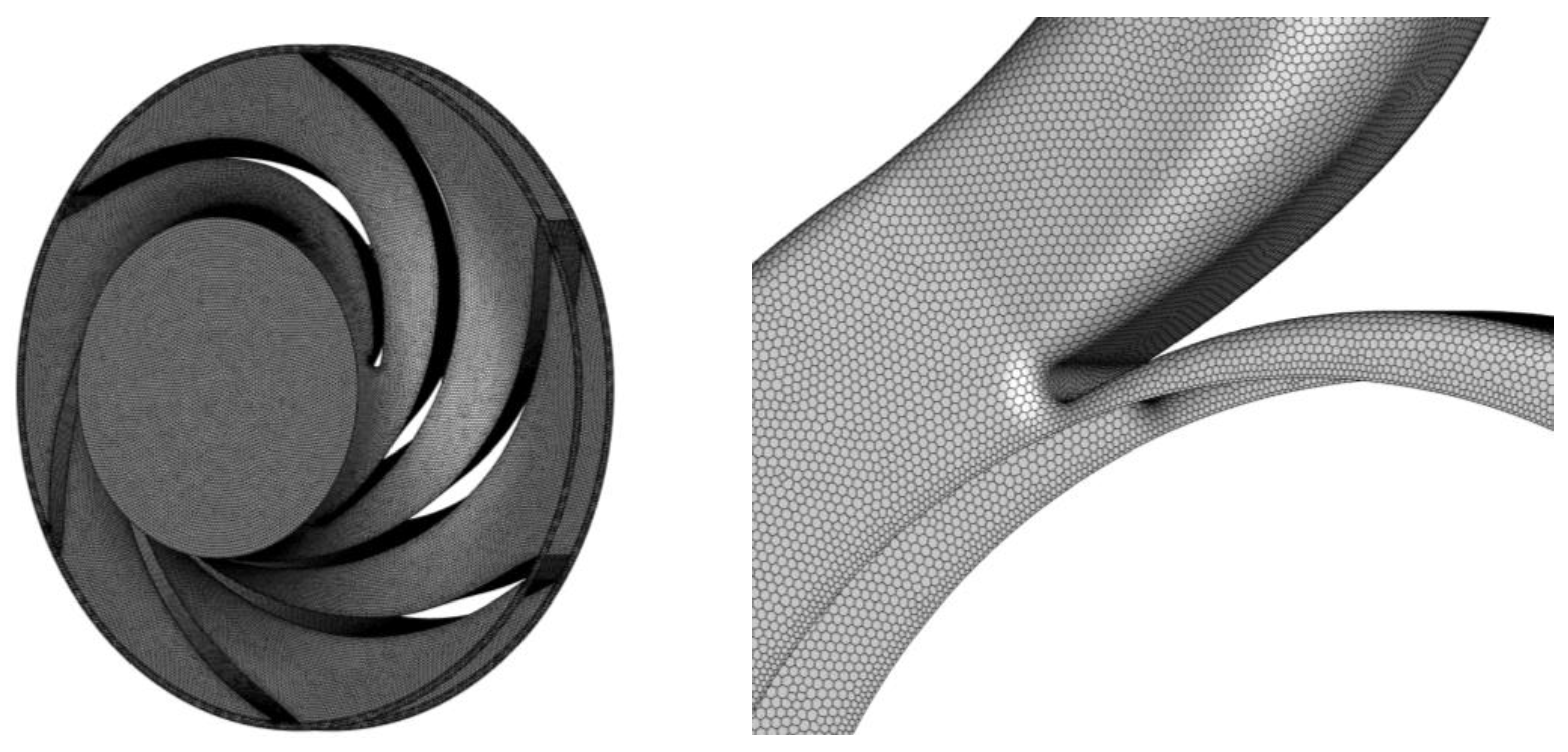
Polyhedral mesh was applied for the discretization of the computational domain. The flow components and small geometric features were locally encrypted to ensure that the nearest wall’s grid size met the fluid model’s requirements and that the flow channel’s geometry was restored to the maximum extent possible [26]. The mesh of the prism layer was stretched at the inlet and outlet to ensure that the flow had been fully developed. Figure 2 shows the resulting unstructured mesh, and Figure 3 shows a close-up of the meshing of some of the components.
3.2. Grid Independence Tests and Model Validation
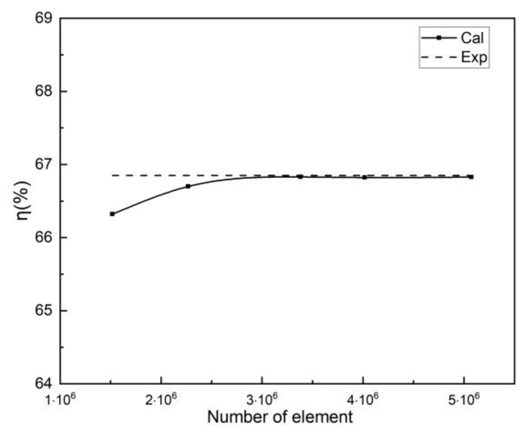
Five sets of different grids were considered to verify the independence of the grid number. The specific grid data are presented in Table 2. For accuracy, the number of boundary layers at the inlet and outlet was set to 7, with the finest grid size; the growth rate from the boundary layer was set at 1.2; and the transient ratio was set at 0.272. The average skewness of the generated polyhedral mesh was 0.015, and the maximum skewness was kept at less than 0.6.
The efficiency of the centrifugal pump was used as a criterion for the mesh independent studies. It was accepted that when the error of efficiency (through comparison with experimental data [26]) was less than 1%, the grid met the accuracy requirements. The computational time and resources required for the numerical calculation were considered during the studies. As seen in Figure 4, the calculation results tended to smooth out and were extremely close to the experimental data, with an increase in the number of meshes. Mesh 3, with 3381292 as the total grid number, was considered to be the final calculation mesh, which was a compromise for the consideration of both the calculation accuracy and the calculation resources [26].
The head was calculated as:
where and were the inlet and outlet pressures of the centrifugal pump, respectively; g is the gravity; and is the density of the fluid.
The hydraulic efficiency η of the system is calculated as:
where P is the input power and is the effective output power, and they can be calculated as:
where T is the impeller torque, n is the speed of the impeller of the centrifugal pump (r/min), and Q is the flow rate in the centrifugal pump (m3/h). Furthermore, the power of shaft is calculated as:
where M (N⋅m) is the torque of the impeller of the centrifugal pump around the shaft.
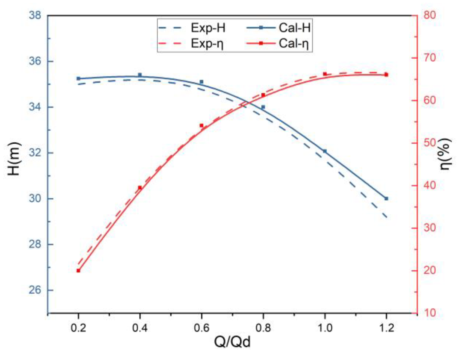
With the selected mesh as mentioned above, the simulation was further validated with the experimental data [26]. For the validation case, the speed of the centrifugal pump was fixed to 2900 r/min. All other parameters remained the same, and only the flow rate of the centrifugal pump was changed to perform the calculation. was the designed flow rate, and was the ratio of the actual flow rate to the designed flow rate. As shown in Figure 5, the relative errors of the head and the efficiency were 0.96% and 0.71%, respectively. The maximum deviation was less than 1% over the entire flow range. Therefore, the numerical results obtained for the centrifugal pump were in good agreement with the experimental results, and highly accurate results were obtained under different flow conditions.
4. Results and Discussion
4.1. Pump Performance
The head and the efficiency are the two fundamental parameters that dictate the performance of a pump. The head can be analyzed by calculating the area-averaged total pressure at the inlet and outlet sections of the domain. The pump efficiency is related to the speed and the shaft torque generated under conditions of static pressure distribution at the impeller blade surface [6].
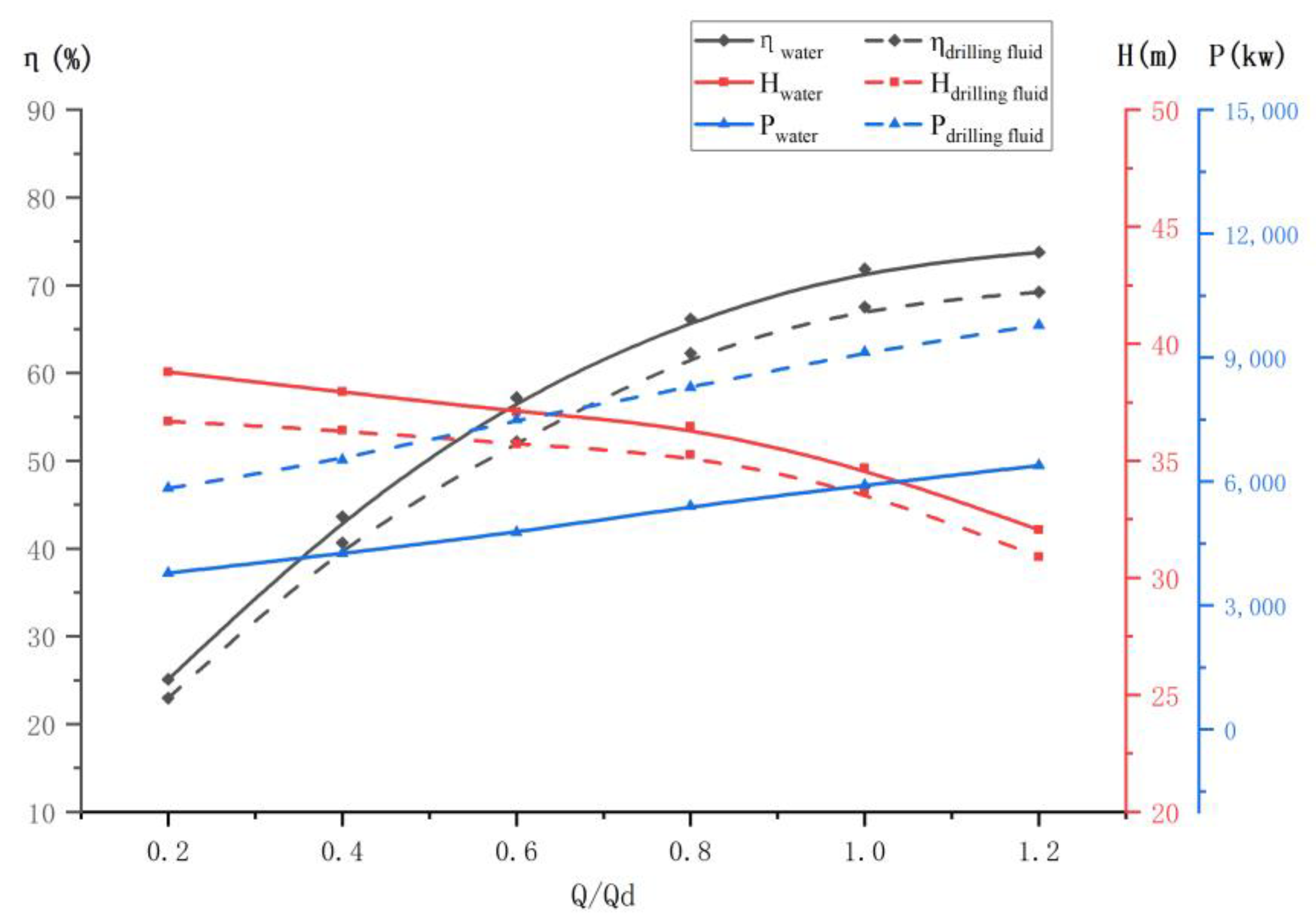
The results of the pumps’ performance are given in Figure 6. As seen in this figure, the head of the water pump was higher than that of the drilling fluid pump, while the power of the water pump was lower than that of the drilling fluid pump. This could be attributed to the fact that the viscosity dissipation of the drilling fluid was higher than that of the water as the blades consumed mechanical energy through friction with the fluid contact during the operation of the centrifugal pump. However, as the drilling fluid was more viscous and denser than the water, it had higher torque, and therefore, more power was generated under the conditions of the same speed. In addition, as the flow rate increased, the difference in efficiency between the drilling fluid and the water went up. From a practical point of view, this was mainly because, in the operation of the centrifugal pumps, the causes of the loss and the impact were the off-stream and other off-work factors, in addition to the viscosity of the medium.
4.2. Pressure Distributions
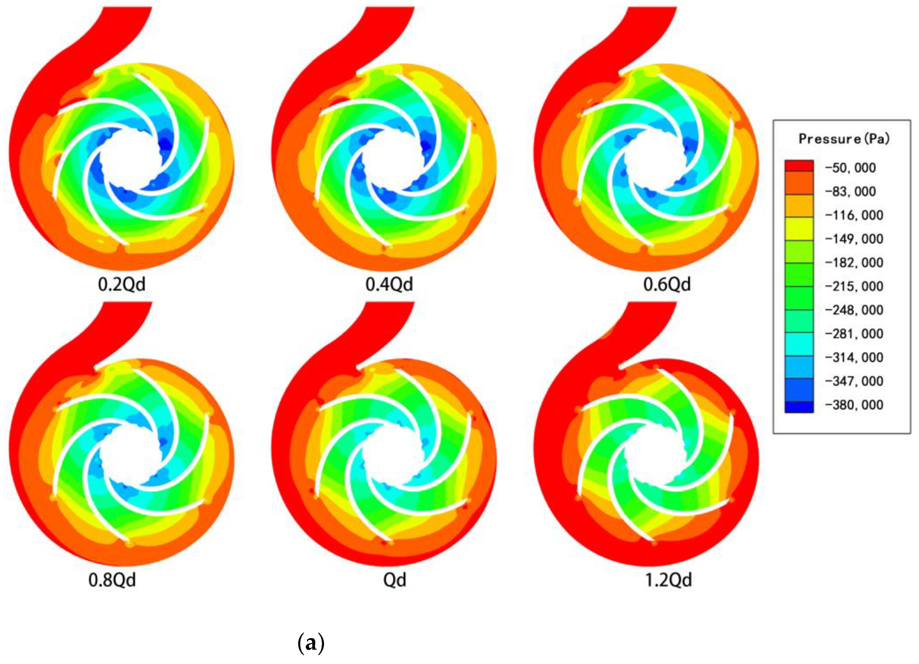
In order to develop an in-depth understanding of the external characteristics of the drilling fluid pump, six cases ( = 0.2, 0.4, 0.6, 0.8, 1, and 1.2) are discussed in this subsection. The condition of constant speed was still fulfilled for the different cases. Figure 7 shows the pressure cloud when the centrifugal pump was steady. In Figure 7, the simulation results of the pressure contours are presented and compared with the results of the centrifugal pump with water. Overall, as shown in Figure 7, the lower-pressure areas were concentrated at the impeller inlet. As the flow rate grew, the pressure at the impeller inlet and in the flow path near the volute increased significantly. This indicated that the converted pressure energy was utilized by the centrifugal pumps in a small amount under the conditions of low flow rates, and the extent of the conversion of the pressure energy within the impeller path increased as the flow rate increased. A certain drop in pressure was observed under the conditions of low flow rates when the liquid reached the inlet of the impeller. As the flow rate increased, the pressure difference between the inlet and outlet of the pump gradually decreased, and correspondingly, the hydraulic head decreased as the flow rate increased.
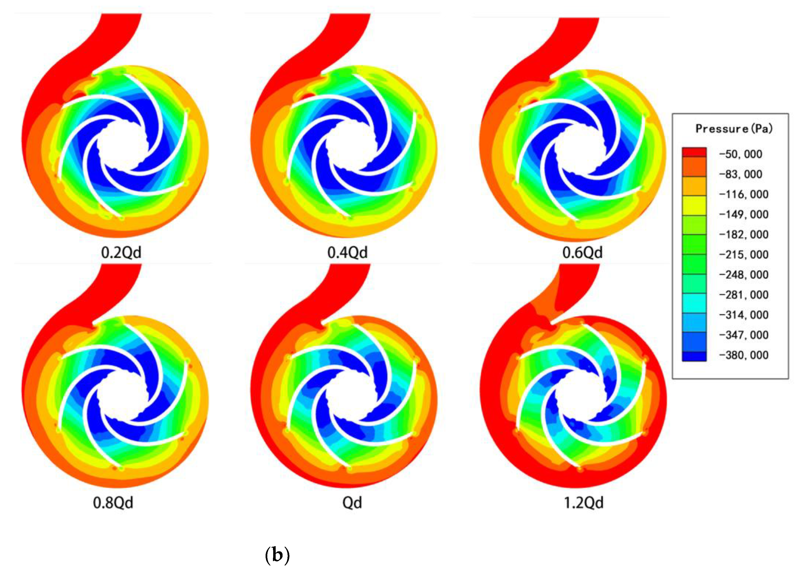
For the comparison of the cases with water and drilling fluid, it could be seen that the pressure around the impeller associated with the drilling fluid was significantly stronger than that associated with the water, and the strength could be attributed to the action of the viscous forces. The lower-pressure region was concentrated at the pressure surface of the blades, the wall surface of the volute, and the volute outlet. The pressure difference between the inlet and outlet of the impeller and the front chamber decreased as the viscosity increased under the conditions of the same flow rate. This also proves that the head decreased with the increasing viscosity. The results indicate that the head and efficiencies of the drilling fluid were lesser than those of the water, and this could be attributed to the fact that high pressure was required to move the highly viscous drilling fluid, resulting in the loss of mechanical energy.
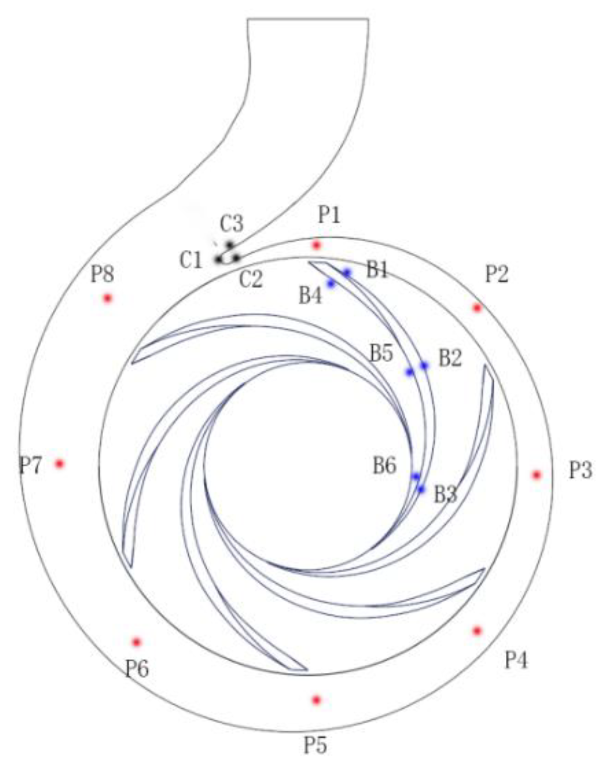
The annular space is the space of transition between a volute and an impeller, and it significantly influences the internal flow field, as well as the external characteristics [5]. Therefore, as shown in Figure 8, eight probing points (P1 to P8) were selected within the volute to monitor the pressure fluctuations. In addition, the surface pressure of one specific blade was investigated. In Figure 8, B1, B2, and B3 represent the pressure sides (PSs) of the blade, and B4, B5, and B6 represent the suction sides (SSs) of the blade. Furthermore, C1, C2, and C3 were chosen around the volute tongue between the volute path and the impeller.
The dimensionless pressure fluctuation coefficient was obtained as follows:
where is the instantaneous total local pressure, is the average pressure (averaged hourly) at the monitoring point, and is the circumferential velocity at the outer edge of the impeller.
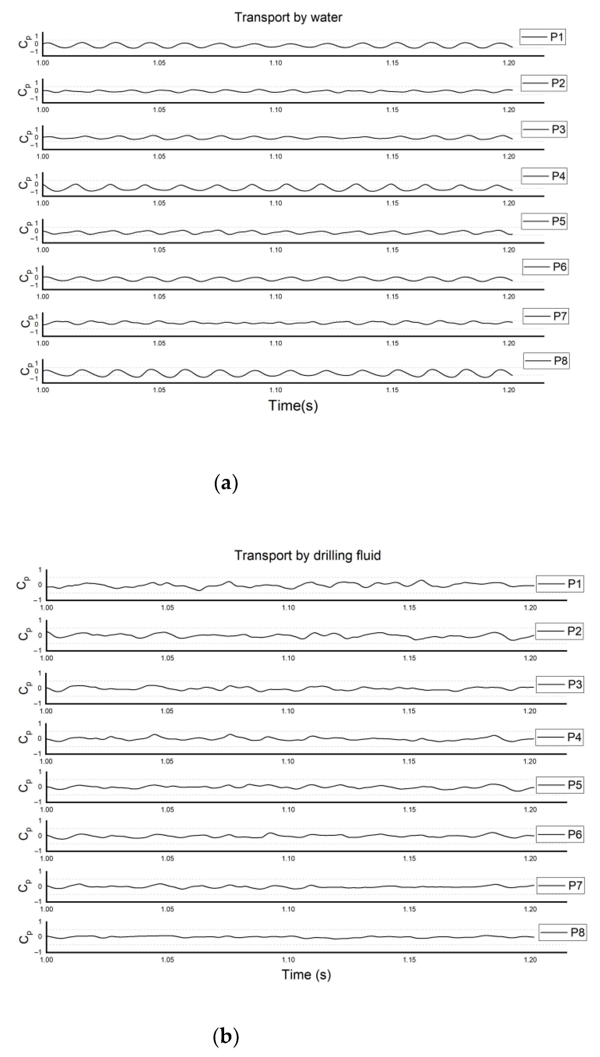
The pressure fluctuations in P1–P8 are shown in Figure 9. By comparing the subfigures, it was found that the variation was significant for P1 and P8, and this could be attributed to the fact that the energy converted by the impeller was mostly caused by the movement of the impeller and the volute tongue, and, therefore, significant pressure fluctuations resulted. In contrast, the variation was irregular for the drilling-fluid case at P6–P8 (as shown in Figure 9b), which could be attributed to the effects of the large viscous forces causing a large friction force for the fluid near the wall. Thus, the pressure did not vary explicitly with the rotation of the impeller. This could be attributed to the blocking effect exerted by the volute tongue on the fluid flow under the conditions of varying viscosities or the differences in the radial or axial velocity of the fluid at the different cross-sections. It is also suggested that the flow of the fluid at the small cross-section of the volute was more sensitive to the rotation of the impeller.
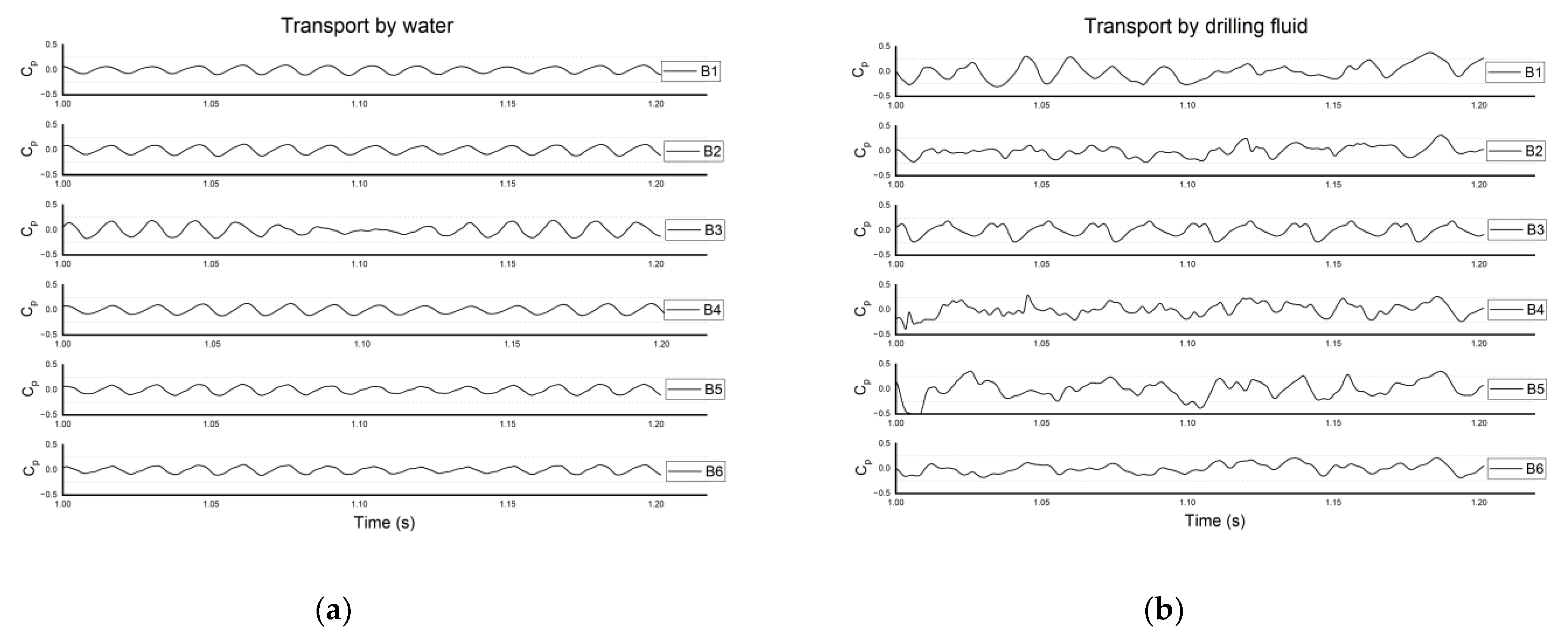
For the pressure distribution on the blade surface, the simulation results are shown in Figure 10. Similar patterns were observed for all the points in the case of the water (Figure 10a). A smooth change was observed at B3. The change was smoother than the change at B6. This could be attributed to the formation of vortex clusters in the water flow. This phenomenon results in small local changes in pressure. On the other hand, in the case of the drilling fluid, as shown in Figure 10b, the pressure fluctuated more regularly on the PS surface than on the SS surface during the transport of the drilling fluid. This could be attributed to the effects of the viscous forces and the properties of the fluid flowing out of the SS face. The flow of the drilling fluid at this end was highly irregular, and this could be attributed to the pressure generated by the blades. Therefore, the amount of energy dissipated under these conditions was more than that dissipated in the case of the water.
A regular effect was exerted by the flow on the spacer tongue (Figure 11a). The variation at C3 was more significant. The secondary flow phenomenon at C3 was considered and therefore the variation at this point was irregular. As the impeller rotated, the variation at C2 was more frequent, but of a smaller magnitude, compared to C1 and C3 (Figure 11b). This indicated that the influence of the drilling fluid on the flow characteristics at C2 was less when the flow rate was the design flow rate. These could be attributed to the viscous forces, which caused a significant reduction in pressure at C2 after fluid action at C1.
The overall radial force of the impeller was also investigated, and it can be obtained by combining the X-directional and Y-directional force components as follows:
where and are the components of the radial force along the X and Y directions, respectively. The results are given in Figure 12, where the flow became steady inside the impeller at . As for the water case, the radial force fluctuated periodically. The frequency of fluctuation, in this case, was the same as the blade frequency, indicating that one rotational cycle involved six distinct fluctuations. When a centrifugal pump transports a drilling fluid, several radial forces greater than those observed for water are observed, and they are mostly caused by the great viscosity of the fluid. However, most of the fluctuations were small in magnitude and irregular in shape. Figure 13b reveals that the vortex clusters attached to the PS surface of the impeller remained intact during the transport of the drilling fluid at . This was potentially responsible for the erratic variations in the radial force.
4.3. Turbulent Kinetic Energy and Velocity Distributions
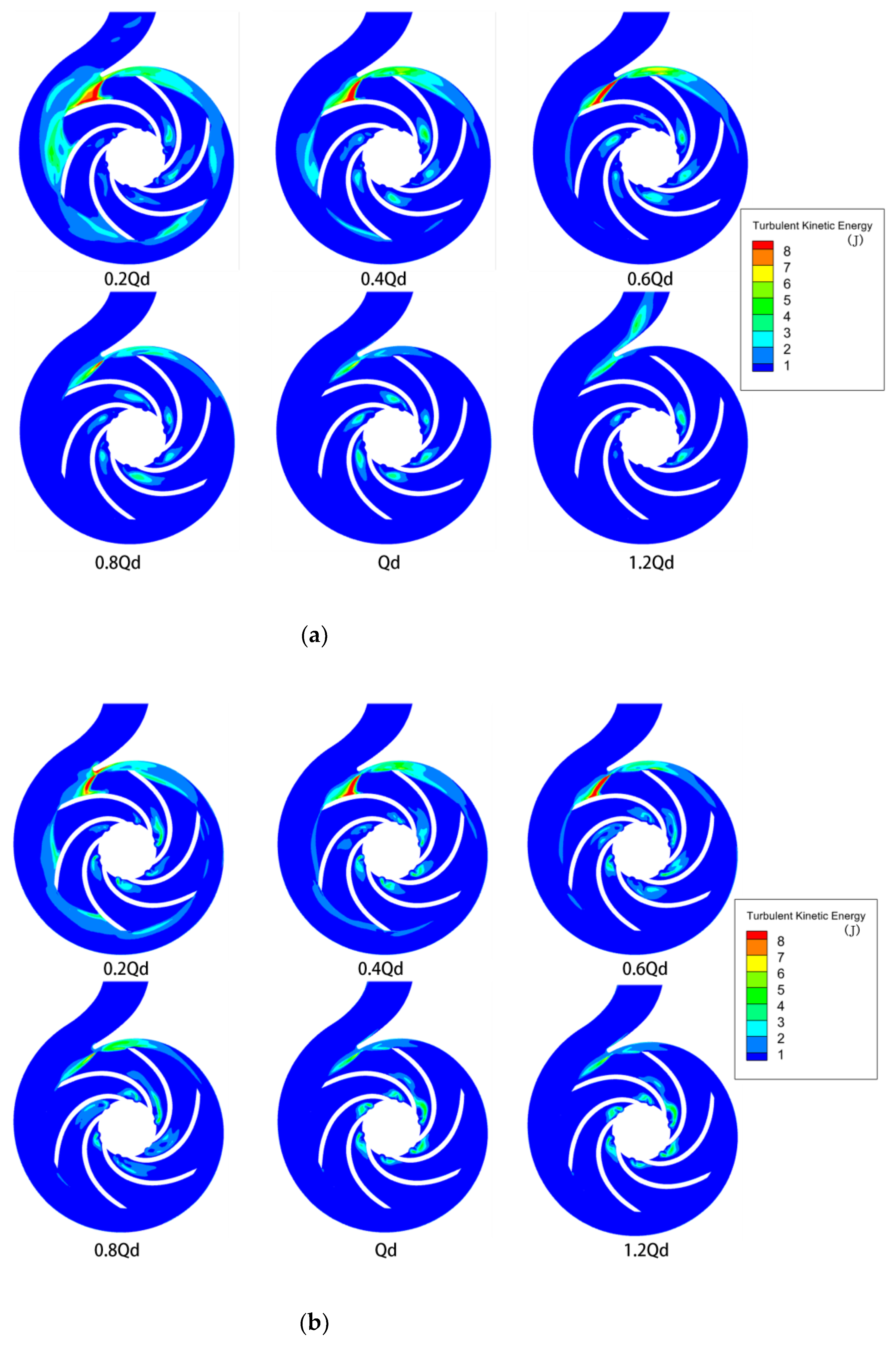
The distributions of turbulent kinetic energy inside the pump are given in Figure 13. It is shown that for the cases of Q < 0.6 Qd, large vortex clusters formed within the impeller, and, therefore, the energy loss was high. As the flow rate increased, areas of high turbulent energy at small volute casing cross-sections and vortex clusters formed between the blades. In the case of the drilling fluid, as shown in Figure 13b, when the flow rate was low, a high turbulent energy region formed near the blades, away from the inlet, which was a result of the effect of the viscosity. As the flow rate increased, the vortex clusters became concentrated between the impellers close to the inlet. The region of high entropy (present within the impeller) was primarily located near the outlet of the impeller. The energy loss in this region was caused by the shear effects generated between the outlet fluid of the impeller and the fluid in the volute region. These observations may also be attributed to the dynamic and static interference effects.
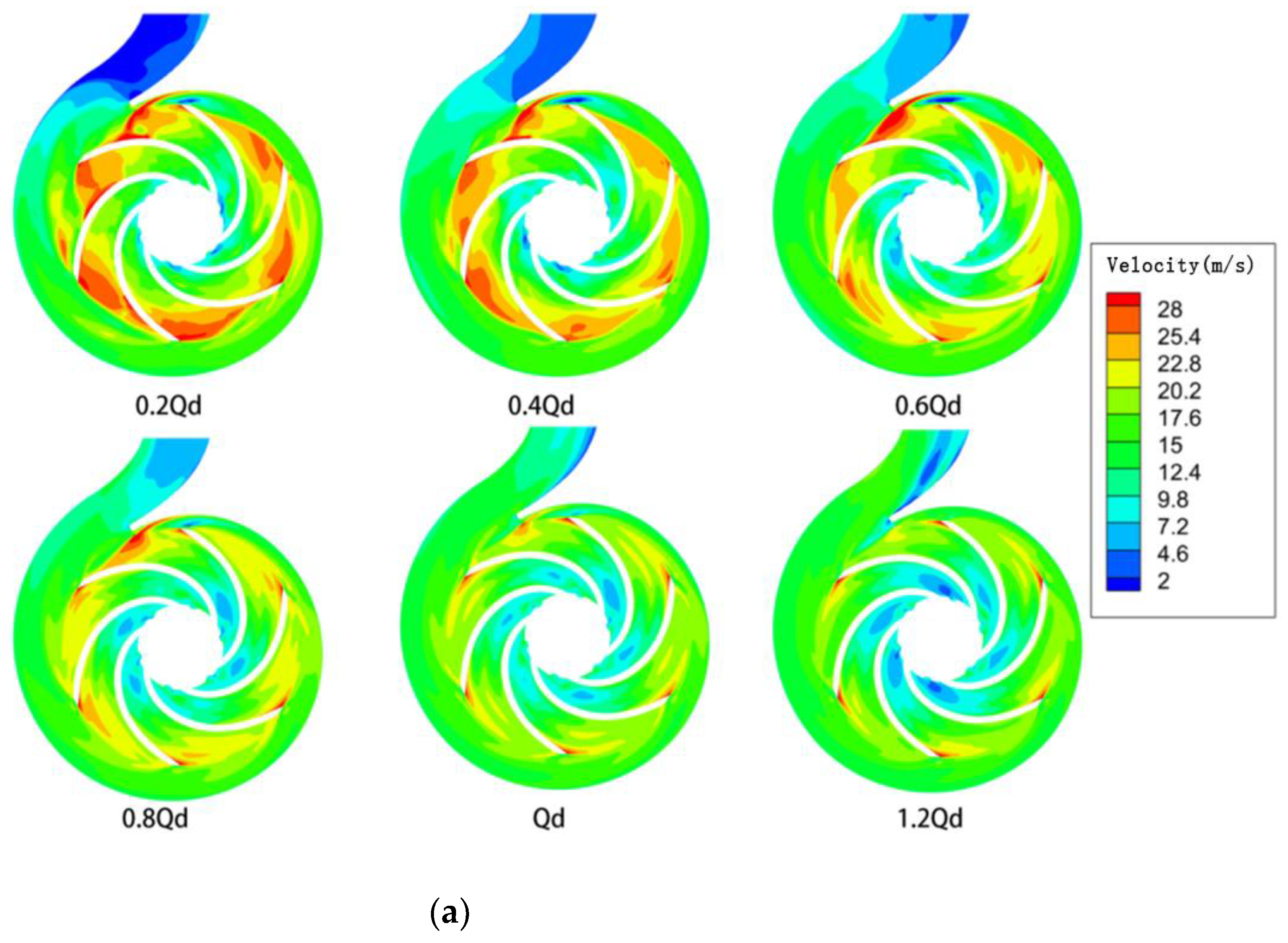
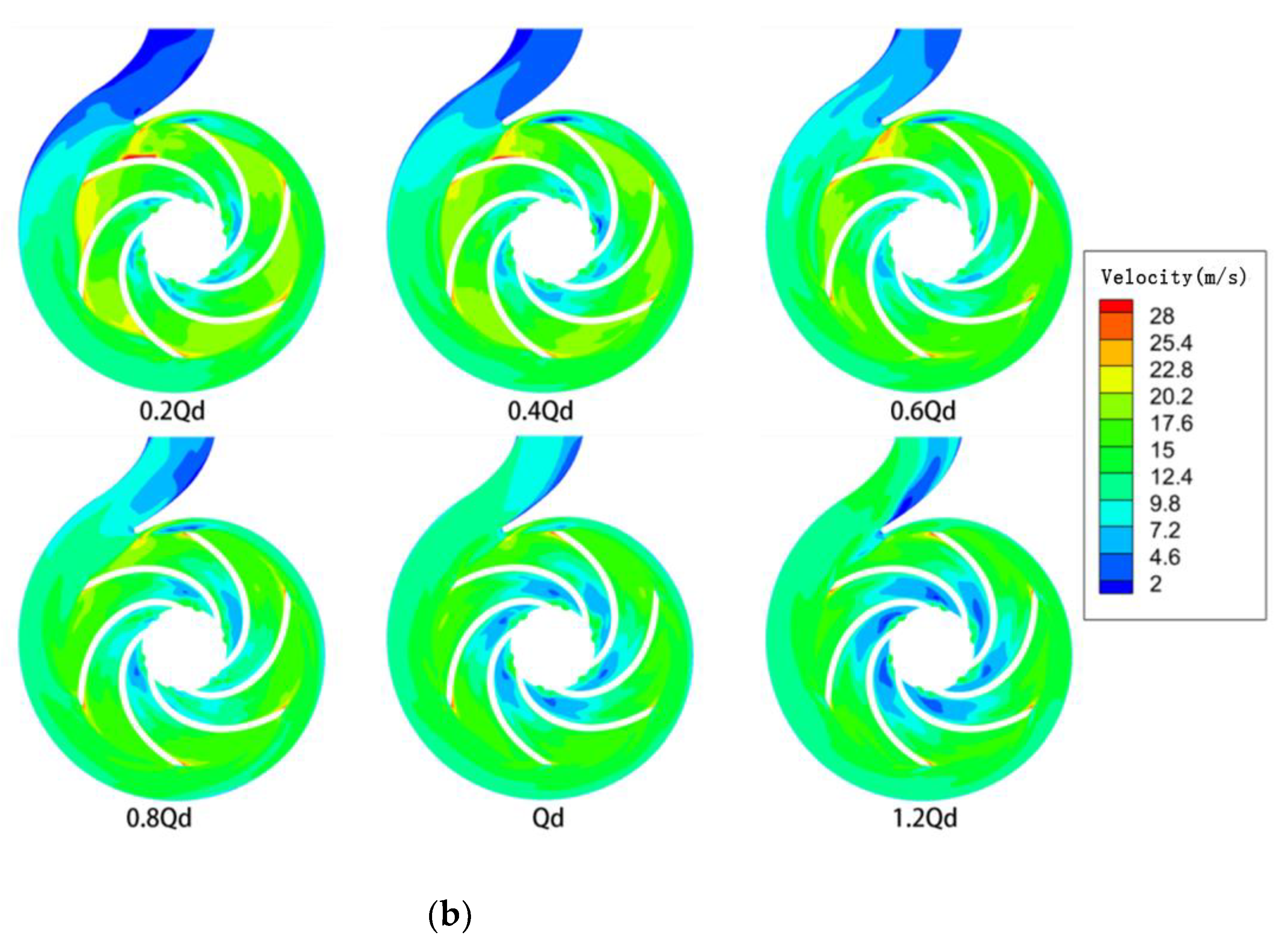
As shown in Figure 14a, the flow path between the outer edges of the blades produced large velocities, and the flow was more turbulent when = 0.2. An obvious low-velocity zone existed at the volute tongue. The fluid velocity in the impeller flow channel increased and that near the low-speed zone decreased when the flow rate increased to 0.8 . The extent of flow achieved inside the impeller path was significantly improved, and the flow line was evenly distributed. A prominent swirl structure was not formed inside the flow channel. A significant change was not observed when the flow rate was less than 0.6 (Figure 14b). As the flow rate increased, a large low-velocity zone formed between the impeller and the volute casing near the wall. This indicates that the drilling fluid was more viscous and exerted a greater effect on the velocity than the water. When , the flow tended to stabilize, but the secondary flow phenomenon was observed in the region where the impeller was close to the outlet.
An analysis of Figure 14 reveals that the flow velocity of the fluid was not uniformly distributed throughout the flow path. The impact at the leading edge of the impeller blades and the trailing edge of the blades resulted in a sudden increase in flow velocity. This phenomenon was particularly aggravated under high flow conditions. However, after the liquid flowed into the stationary front chamber, its velocity gradually decreased. This resulted in flow detachment at the back of the blades. Under these conditions, the flow velocity was lower than the flow velocity recorded at the front of the blades. When the pump drew different liquids, the volume of the drilling fluid drawn at the low flow conditions was low, and this could be attributed to the influence of viscous forces. The flow detachment range at the back of the trailing edge of the blades decreased under the action of high viscosity. At high flow rates, the drilling fluid formed a local area of low velocity at the impeller inlet, creating a vortex.
5. Conclusions
In this paper, the SST k-ω turbulence model is used to study Newtonian and non-Newtonian power-law fluids transported separately in a centrifugal pump at different flow rates. The pressure of individual blades and the overall radial force of the impeller were evaluated, as was the fluid flow pattern at small cross-sections of the volute. We also separately plotted the pressure, velocity, and turbulent energy clouds inside the centrifugal pump and analyzed the results generated. These results can provide insight into additional flow details that will benefit future improvements to centrifugal pumps. The details of the results are as follows:
- The blades consumed mechanical energy through friction with the fluid contact during the operation of the centrifugal pump. The viscosity of the drilling fluid was higher than that of the water. Therefore, the head and efficiency of the drilling fluid were lesser than those of the water at the same flow rate. However, stronger torque and lager power were generated for the drilling-fluid cases. In practice, when transporting high-viscosity non-Newtonian fluids, attention should be paid to the reasonable use of larger rotating speeds in centrifugal pumps as a means of achieving greater efficiency.
- For the drilling-fluid cases, irregular variations in pressure distribution were observed, which could be attributed to the effects of viscous forces causing the fluid to cling to the volute wall. The pressure did not change with changes in the mode of impeller rotation. This could be attributed to the blocking effect of the volute. This affected the flow conditions under different viscosity conditions and potentially contributed to the differences in the radial or axial velocity at the different cross-sections. It was also observed that the nature of the fluid flow in the small cross-sections of the volute was highly sensitive to the rotation of the rotor.
- When the pump drew the power-law fluid, as the flow rate increased and after it flowed into the stationary front chamber, its velocity gradually decreased. This resulted in flow detachment at the back of the blades. At the same time, the non-Newtonian fluid became less detached from the flow at the blade, and swirls were generated at the impeller inlet. The effects of shear collision exerted on the outlet fluid of the impeller and the fluid in the snail casing area, as well as the dynamic and static interferences, made the non-Newtonian power-law fluid consume more mechanical energy than the water.
Author Contributions
Methodology, J.H.; Software, K.L.; Validation, K.L.; Formal analysis, K.L.; Resources, W.S.; Data curation, K.L.; Writing—original draft, K.L.; Writing—review & editing, J.H.; Supervision, X.Z. All authors have read and agreed to the published version of the manuscript.
Funding
This research was funded by the National Key Research and Development Program of China (No. 2021YFC2800803, 2021YFC2801503).
Institutional Review Board Statement
This article does not contain any studies with human participants or animals performed by any of the authors.
Data Availability Statement
Data sharing is not applicable to this article.
Acknowledgments
The authors are grateful for the support from the department and the university.
Conflicts of Interest
The authors declare that they have no conflict of interest.
References
- Guan, X.F. Modern Pump Theory and Design; China Astronautic Publishing House: Beijing, China, 2011. [Google Scholar]
- Lee, T.H. Centrifugal Pumps. In Drilling Fluids Processing Handbook; Elsevier Inc.: Newyork, NY, USA, 2005; pp. 465–520. [Google Scholar]
- Pumps, S. Centrifugal Pump Handbook, 3rd ed.; Sulzer Pumps Ltd.: Winterthur, Switzerland, 2010. [Google Scholar]
- Wu, Y.; Li, S.; Liu, S.; Dou, H.S.; Qian, Z. Vibration of Hydraulic Machinery; Springer: Berlin/Heidelberg, Germany, 2013. [Google Scholar] [CrossRef]
- Brennen, C.E. Hydrodynamics of Pumps: Preface; Cambridge University Press: Oxford, UK, 2011; pp. 105–132. [Google Scholar] [CrossRef] [Green Version]
- Kang, C.; Zhang, G.; Li, B.; Feng, Y.; Zhang, Z. Virtual reconstruction and performance assessment of an eroded centrifugal pump impeller. Proc. Inst. Mech. Eng. Part C J. Mech. Eng. Sci. 2017, 231, 2340–2348. [Google Scholar] [CrossRef]
- Kalombo, J.; Haldenwang, R.; Chhabra, R.P.; Fester, V.G. Centrifugal Pump Derating for Non-Newtonian Slurries. J. Fluids Eng. 2014, 136, 031302. [Google Scholar] [CrossRef]
- Leuprecht, A.; Perktold, K. Computer Simulation of Non-Newtonian Effects on Blood Flow in Large Arteries. Comput. Meth. Biomech. Biomed. Eng. 2001, 4, 149–163. [Google Scholar] [CrossRef] [PubMed]
- Zhao, B.; Yuan, S.; Liu, H.; Tan, M. Three-Dimensional Coupled Impeller-Volute Simulation of Flow in Centrifugal Pump and Performance Prediction. Chin. J. Mech. Eng. 2006, 19, 59–62. [Google Scholar] [CrossRef]
- Pullum, L.; Graham, L.J.W.; Rudman, M. Centrifugal pump performance calculation for homogeneous and complex heterogeneous suspensions. J. South. Afr. Inst. Min. Metall. 2007, 107, 373–379. [Google Scholar] [CrossRef] [Green Version]
- Graham, L.; Pullum, L.; Slatter, P.; Sery, G.; Rudman, M. Centrifugal Pump Performance Calculation for Homogeneous Suspensions; Wiley: New York, NY, USA, 2009. [Google Scholar] [CrossRef]
- Crawford, J.; Sittert, F.V.; Walt, M.V.D. The performance of centrifugal pumps when pumping ultra-viscous paste slurries. J. S. Afr. Inst. Min. Metall. 2011, 112, 959–964. [Google Scholar] [CrossRef]
- Ma, X.D.; Li, Z.F.; Yu, H.; Wu, D.Z.; Wang, L.Q. Experimental Study on a Medium Consistency Pump. J. Fluids Eng. 2013, 135, 104503. [Google Scholar] [CrossRef]
- Zhou, W.Y.; Yu, D.; Wang, Y.; Shi, J.; Gan, B. Research on the Fluid-induced Excitation Characteristics of the Centrifugal Pump Considering the Compound Whirl Effect. Facta Univ. Ser. Mech. Eng. 2021. [Google Scholar] [CrossRef]
- Xuan, L.N.; Huan, X.L. The Simulation of Non-Newtonian Power-Law Fluid Flow in a Centrifugal Pump Impeller. J. Appl. Mech. Eng. 2016, 5, 381–390. [Google Scholar] [CrossRef]
- Aldi, N.; Buratto, C.; Casari, N.; Dainese, D.; Mazzanti, V.; Mollica, F.; Munari, E.; Occari, M.; Pinelli, M.; Randi, S. Experimental and Numerical Analysis of a Non-Newtonian Fluids Processing Pump. Energy Procedia 2017, 126, 762–769. [Google Scholar] [CrossRef]
- Aldi, N.; Buratto, C.; Pinelli, M.; Spina, P.R.; Suman, A.; Casari, N. CFD Analysis of a Non-newtonian Fluids Processing Pump. Energy Procedia 2016, 101, 742–749. [Google Scholar] [CrossRef]
- Buratto, C.; Occari, M.; Aldi, N.; Casari, N.; Suman, A. Centrifugal pumps performance estimation with non-Newtonian fluids: Review and critical analysis. In Proceedings of the European Conference on Turbomachinery Fluid Dynamics & Hermodynamics, Stockholm, Sweden, 3–7 April 2017. [Google Scholar]
- Mrinal, K.R.; Siddique, M.H.; Samad, A. Performance prediction of a centrifugal pump delivering non-Newtonian slurry. Part. Sci. Technol. 2018, 36, 38–45. [Google Scholar] [CrossRef]
- Valdés, J.; Becerra, D.; Rozo, D.; Cediel, A.; Ratkovich, N. Comparative analysis of an electrical submersible Pump’s performance handling viscous Newtonian and non-Newtonian fluids through experimental and CFD approaches. J. Pet. Sci. Eng. 2019, 187, 106749. [Google Scholar] [CrossRef]
- Donmez, M.; Yemenici, O. A Numerical Study on Centrifugal Pump Performance with the Influence of Non-Newtonian Fluids. Int. J. Sci. 2019, 8, 39–45. [Google Scholar] [CrossRef]
- Abdolahnejad, E.; Moghimi, M.; Derakhshan, S. Experimental and numerical investigation of slip factor reduction in centrifugal slurry pump. J. Braz. Soc. Mech. Sci. Eng. 2021, 43, 179. [Google Scholar] [CrossRef]
- Achour, L.; Specklin, M.; Belaidi, I.; Kouidri, S. Numerical Assessment of the Hydrodynamic Behavior of a Volute Centrifugal Pump Handling Emulsion. Entropy 2022, 24, 221. [Google Scholar] [CrossRef] [PubMed]
- Chen, X.; Fan, H.; Ji, R.; Li, C.; Wang, Y. Four-Parameter Rheological Model and Its Application in Cementing Slurry. Pet. Drill. Tech. 2013, 41, 76–81. [Google Scholar] [CrossRef]
- Menter, F.R.; Kuntz, M.; Langtry, R. Ten years of industrial experience with the SST turbulence model. In Turbulence, Heat and Mass Transfer 4; Begell House, Inc.: Newyork, NY, USA, 2003; pp. 625–632. [Google Scholar]
- Zheng, L. Unsteady Flow Mechanism of Centrifugal Pump Port Ring Clearance. Ph.D. Thesis, Zhejiang Sci-Tech University, Hangzhou, China, 2019. [Google Scholar]
Figure 1.
Schematic diagram of the simulation fluid domain of the pump.

Figure 2.
Unstructured grid division of centrifugal pump.

Figure 3.
Local mesh division of the impeller water body and volute.

Figure 4.
Grid-independence validation of the current study.

Figure 5.
Simulation results of the centrifugal pump external characteristics and a comparison with the experiments.
Figure 5.
Simulation results of the centrifugal pump external characteristics and a comparison with the experiments.

Figure 6.
Comparison of the efficiency, head, and power of the water and drilling fluid at different flow rates.
Figure 6.
Comparison of the efficiency, head, and power of the water and drilling fluid at different flow rates.

Figure 7.
Pressure contours in the centrifugal pump. (a) Cases with water; (b) cases with drilling fluid.
Figure 7.
Pressure contours in the centrifugal pump. (a) Cases with water; (b) cases with drilling fluid.


Figure 8.
Monitoring points of the pressure fluctuations in the centrifugal pump.

Figure 9.
Pressure coefficients at the different points within volute (P1–P8). (a) Water case; (b) drilling-fluid case.
Figure 9.
Pressure coefficients at the different points within volute (P1–P8). (a) Water case; (b) drilling-fluid case.

Figure 10.
Pressure coefficients at the different points on blade surface (B1–B6). (a) Water case; (b) drilling-fluid case.
Figure 10.
Pressure coefficients at the different points on blade surface (B1–B6). (a) Water case; (b) drilling-fluid case.

Figure 11.
Pressure coefficients at the different points on the volute spacer tongue (C1–C3). (a) Water case; (b) drilling-fluid case.
Figure 11.
Pressure coefficients at the different points on the volute spacer tongue (C1–C3). (a) Water case; (b) drilling-fluid case.

Figure 12.
Polar diagram of the radial force on the impeller for the different media fluids.

Figure 13.
Turbulent kinetic energy contours in the centrifugal pump. (a) Cases with water; (b) cases with drilling fluid.
Figure 13.
Turbulent kinetic energy contours in the centrifugal pump. (a) Cases with water; (b) cases with drilling fluid.

Figure 14.
Velocity contours in the centrifugal pump. (a) Cases with water; (b) cases with drilling fluid.
Figure 14.
Velocity contours in the centrifugal pump. (a) Cases with water; (b) cases with drilling fluid.


Table 1.
Basic parameters of the centrifugal pump.
| Parameters | Value | |
|---|---|---|
| Design flow rate | 45 m3/h | |
| Design head | 31.8 m | |
| Design efficiency | 66.85% | |
| Rated speed | 2900 rpm | |
| Specific speed | 90 | |
| Number of blades | Z | 6 |
| Volute inlet diameter | 86 mm | |
| Volute outlet diameter | 161 mm | |
| Volute base circle diameter | 173 mm | |
| Pump inlet diameter | 80 mm | |
| Pump outlet diameter | 50 mm | |
Table 2.
Distribution of the grid numbers in each domain.
| Mesh | Impeller | Volute | Front Chamber | After Chamber | In-Pipe | Out-Pipe | Total |
|---|---|---|---|---|---|---|---|
| 1 | 449,862 | 53,480 | 145,495 | 307,532 | 147,355 | 412,901 | 1,516,625 |
| 2 | 872,733 | 600,705 | 297,415 | 307,532 | 83,289 | 108,078 | 2,267,952 |
| 3 | 1,333,972 | 1,251,006 | 297,415 | 307,532 | 83,289 | 108,078 | 3,381,292 |
| 4 | 1,333,972 | 1,251,006 | 500,475 | 500,873 | 195,580 | 235,695 | 4,017,601 |
| 5 | 1,676,438 | 1,965,268 | 500,475 | 500,873 | 195,580 | 235,695 | 5,074,329 |
Disclaimer/Publisher’s Note: The statements, opinions and data contained in all publications are solely those of the individual author(s) and contributor(s) and not of MDPI and/or the editor(s). MDPI and/or the editor(s) disclaim responsibility for any injury to people or property resulting from any ideas, methods, instructions or products referred to in the content. |
© 2023 by the authors. Licensee MDPI, Basel, Switzerland. This article is an open access article distributed under the terms and conditions of the Creative Commons Attribution (CC BY) license (https://creativecommons.org/licenses/by/4.0/).
Share and Cite
MDPI and ACS Style
Hu, J.; Li, K.; Su, W.; Zhao, X. Numerical Simulation of Drilling Fluid Flow in Centrifugal Pumps. Water 2023, 15, 992. https://doi.org/10.3390/w15050992
AMA Style
Hu J, Li K, Su W, Zhao X. Numerical Simulation of Drilling Fluid Flow in Centrifugal Pumps. Water. 2023; 15(5):992. https://doi.org/10.3390/w15050992
Chicago/Turabian StyleHu, Jianxin, Ke Li, Wenfeng Su, and Xinyi Zhao. 2023. "Numerical Simulation of Drilling Fluid Flow in Centrifugal Pumps" Water 15, no. 5: 992. https://doi.org/10.3390/w15050992
Note that from the first issue of 2016, this journal uses article numbers instead of page numbers. See further details here.