Article

Effect of Unbalanced Magnetic Pull of Generator Rotor on the Dynamic Characteristics of a Pump—Turbine Rotor System

1
Henan Luoning Pumped Storage Co., Ltd., Luoning 471700, China
2
College of Water Resources and Civil Engineering, China Agricultural University, Beijing 100083, China
3
Department of Energy and Power Engineering, Tsinghua University, Beijing 100084, China
*
Author to whom correspondence should be addressed.
Water 2023, 15(6), 1120; https://doi.org/10.3390/w15061120
Submission received: 27 February 2023 / Revised: 6 March 2023 / Accepted: 11 March 2023 / Published: 15 March 2023
(This article belongs to the Special Issue Advancements in the Complex Vortex Flow in Hydraulic Machinery)

Abstract

:
In pumped storage units, the rotor-bearing electromagnetic system is under the joint influence of hydraulics, mechanics, and electromagnetics, and the mechanism of unit vibration problems is very complex to investigate. ANSYS software is used to establish a three-dimensional model of a pumped storage power plant’s rotor-bearing electromagnetic system, and the stiffness coefficient of the unbalanced magnetic traction forces is calculated using the Fourier series of the magnetic conductivity of the air gap. This shows that the nonequilibrium magnetic attraction increases non-linearly with increasing excitation current and eccentricity of the rotor. At each order, the critical velocity of the rotor system increases as the stiffness factor of the bearing increases, with the greatest increase in critical velocity at the third and fourth orders. In the first-order mode-oscillation pattern, the unbalanced magnetic attraction has an effect on the intrinsic frequency of the transverse oscillation, with a reduction in the amplitude of the intrinsic frequency by 34.65%. Axial and transverse modal vibrations manifest themselves as upward and downward motions and transverse oscillations in different portions of the rotor system, respectively, whereas torsional modal vibrations manifest as a radial broadening or reduction in the generator rotor, runner, and coupling portions of the rotor system. The results of the study provide a theoretical foundation and a computational method for the dynamic analysis and design of the rotor system of pumped storage power stations.

1. Introduction

Pumped storage power plants play an irreplaceable role in energy storage and in ensuring a stable supply of energy to the power system. The alternating operation of pumped storage power plants under generation and pumping conditions is characterized by frequent starts and stops, a high rotational speed, and a high hydraulic head. The shaft unit is a complex mechanical bearing-rotor system, which results in a degree of vibration due to the unit’s own operating characteristics as well as the complexity of the operating environment [1]. As an important branch of electromagnetic excitation, unbalanced magnetic pull has a significant influence on the vibration characteristics of a device. It is therefore important to investigate the influence of a nonequilibrium magnetic pull on the vibration of rotor systems, for both unit design and condition maintenance purposes.
Analyzing the dynamic characteristics of the main shaft of a pumped storage generator assembly is a complex problem in rotor dynamics that involves mechanical, hydraulic, and electromagnetic factors [2]. Poor manufacturing quality and installation may cause the generator rotor to be eccentric or to be demagnetized during operation due to a partial shorting of the pole caused by a fault in the rotor excitation winding, which will produce a nonequilibrium magnetic attraction between the stator and rotor [3]. This unbalanced magnetic pull acts on the rotor shaft system and the stator core, which will cause vibrations and other problems, and in severe cases will put the safe operation of the unit at risk [4]. Tenhunen et al. [5,6,7] proposed expanding the permeability of the air gap in a Fourier series form in order to derive a more accurate analytical expression for the unbalanced magnetic tension. D Guo [8] used numerical calculation methods and harmonic analysis to analyze the vibration of a three-phase generator model rotor subjected to eccentric forces. Subbiah [9,10,11] combined finite elements and transfer matrices to model the shaft system using the finite-element method and converted the coefficient characteristics to a transfer matrix model. Tianyu Wang [12] used a three-dimensional finite-element analysis (FEA) method to establish the inherent frequencies and vibration modes of a magnetic bearing-rotor system for a high-speed machine tool and determined the bearing stiffness of the three-dimensional FEA model through excitation experiments. Feng Wei [13] proposed a calculation model of the motion trajectory of a synchronous electric spindle considering magneto-thermal coupling and analyzed the variation law of the air gap between the rotor and stator of the built-in motor by calculating the thermal deformation of the spindle. Ma Chenyuan [14] established a mathematical model of a two-rotor bearing system and creatively studied the influence of unbalanced magnetic tension and oil film force on its non-linear phenomenon. Huang Liangyuan [15] proposed a method for modeling coupled electromagnetic dynamics with the introduction of unbalanced magnetic tension. Using rotor speed, air gap length, and unbalanced magnetic pull force as coupling parameters, the coupled simulation of the dynamic and electromagnetic models could be effectively achieved. Zhang Leike et al. [16] used the Runger-Kutta method to analyze the mechanical vibration characteristics of the shaft system of a hydro generator set on the basis of the analytical equation for the unbalanced magnetic pull obtained from the Fourie series expansion of the air-gap permeability, taking into account the distribution of the magnetic logarithm of the motor. Song et al. [17] derived the generator rotor’s electromagnetic stiffness matrix and established a rotor vibration model considering the electromagnetic action of the bearings. The magnetic pull was determined by Richard Perers [18,19] using a finite element method in parallel with simple analytical models for various no-load voltages and loads. For high voltages and large loads, saturation significantly affects the magnitude of the unbalanced magnetic pull. Mattias Wallin [20,21,22] investigated the unbalanced magnetic pull and flux density distribution caused by short circuits between turns of the winding of the magnetic field using experiments and numerical simulations. Ophir Nave [23] presented the concept of the singularly perturbed vector field (SPVF) method and its application to spark ignition turbocharger engines. Given a mathematical/physical model, which consists of hidden multi-scale variables, the SPVF methods transfer (using the change in coordinates) and decompose such a system to fast and slow subsystems.
A pumped storage power station generator set is a typical electromechanical system, which will exhibit complex non-linear dynamics due to the combined effect of mechanical and electromagnetic factors. A simplified model cannot fully reveal the influence of unbalanced magnetic pull on the kinematic characteristics of the system. Therefore, the establishment of a non-linear relationship between the unbalanced magnetic pull and rotor eccentricity and the systematic study of the vibration of the unit shaft system due to the electromagnetic-mechanical affinity factors has become the focus of current work.
This paper establishes a three-dimensional finite-element model of the rotor-bearing electromagnetic system of a pumped storage unit, calculates the critical speed of the shaft system, discusses the effects of changes in the unbalanced magnetic tension stiffness coefficient and the stiffness coefficient of each guide bearing on the low-order critical speed and the intrinsic frequency, and reveals the causes of these effects in terms of vibration characteristics, providing some theory for the safe design and stable operation of the shaft system of pumped storage generating units.

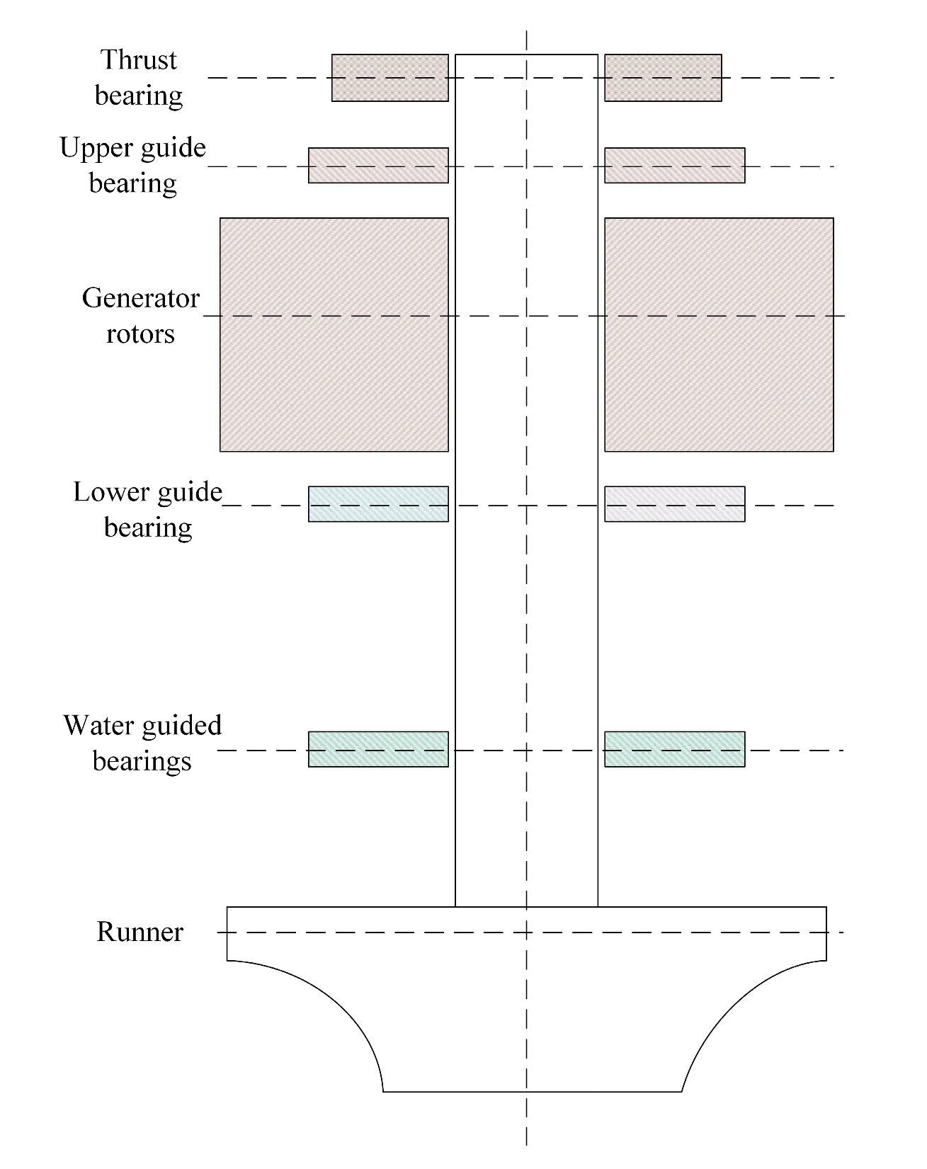
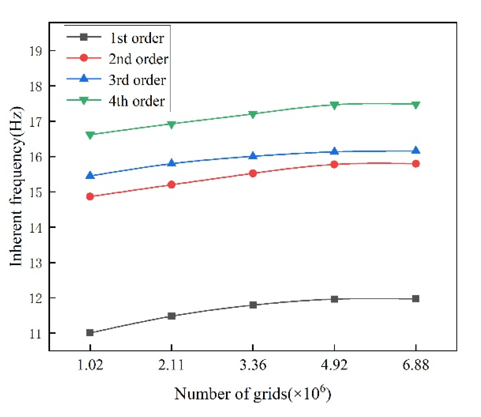
2. Finite Element Calculation Model

2.1. Mathematical Model of Rotor Dynamics

The purpose of modal analysis is to determine the vibration characteristics of the structure, including the vibration mode and critical speed of the structure. The results of structural vibration characteristics are the basic data for structural transient dynamics analysis, harmonic response analysis, and spectral analysis. The free vibration equation for a single degree of freedom system is
M q · · + C q · + K q = 0
where M is the system mass matrix; C is the system generalized damping matrix; K is the system generalized stiffness matrix; q · · , q · , and q are the system node acceleration, velocity, and displacement vectors; and 0 is the zero matrix.
The rotor system of a pumped storage power station unit contains rotating components such as the main shaft, generator rotor, runner, and thrust bearing. Rotor eccentricity is usually generated between the generator rotor and stator components due to the unit’s operating conditions and installation process, which causes the unit’s rotor to generate unbalanced magnetic pull with periodic characteristics and therefore requires consideration of effects such as gyroscopic effects and rotational softening. The damping and stiffness matrices in the free vibration equation are expressed as a function of the rotational speed. The problem of analyzing the inherent vibration of a rotor system is transformed into an eigenvalue problem for the free vibration equation.
The forced vibration equation for a rotor system under an external excitation load is
M q · · + C q · + K q = F
where F is the unbalanced magnetic pull of the rotor system. The unbalanced magnetic pull, as a steady-state periodic load, can be expressed as F = F R ± j F I e i ω t , where ωk is the frequency of the excitation force.

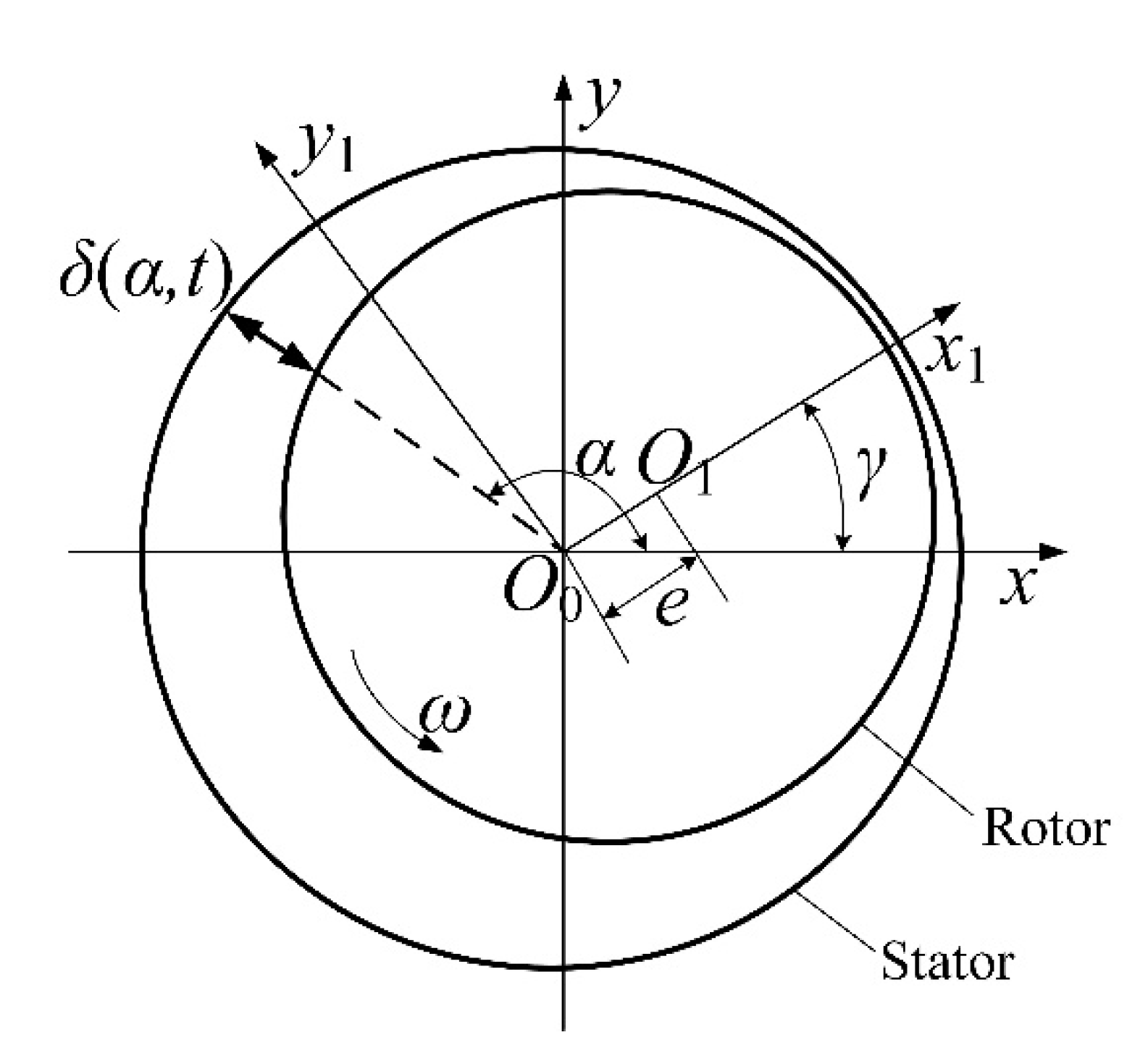
2.2. Generator Air Gap Unbalance Magnetic Pull Model

The uneven gap between the inner cavity of the stator and the outer circle of the rotor, the initial deflection of the shaft, and the swing of the shaft system generated by the hydraulic imbalance will cause the uneven air gap of the stator and rotor, thus generating unbalanced magnetic tension and affecting the dynamic characteristics of the unit. When the eccentricity increases and the shaft deflection reaches a certain level, the elastic recovery force will be equal to the unbalanced magnetic tension and dynamic balance will be achieved. When the electromagnetic vibration of the unit is serious, it will lead to the normal operation of the unit due to the vibration exceeding the standard, and even cause the stator and rotor to touch the grinding accident.
The eccentricity of the rotor of a pumped storage unit generator is shown in Figure 1, where the rotor eccentricity air gap can be approximated as
δ α , t δ 0 e cos α γ
where δ0 is the average length of the air gap when the rotor is not eccentric, α is the angle at the eccentric position, γ is the angle of rotation of the generator rotor, and e is the radial displacement of the generator rotor axis (i.e., rotor eccentricity distance).
The main parameters of the generator for this pumped storage power station are shown in Table 1.
In this paper, the Fourier series expansion of the air-gap permeability is used to integrate the Maxwell stress on the rotor surface and derive the following analytical expression for the non-linear unbalanced magnetic pull f of a three-phase motor when the number of pairs of motor poles is greater than 3.
f = R L π μ 0 k i 2 I j 2 δ 0 2 e 2 δ 0 + 3 e 3 4 δ 0 3 + 15 e 5 16 δ 0 5
In the actual operation of the power station, the variable is mainly the excitation current and rotor eccentricity, where the excitation current affects the magnetic field strength of the air gap between the stator and rotor, which in turn affects the magnitude of the unbalanced magnetic pull. The number of magnetic poles in the pump turbine motor of a pumped storage power station is 6, and the unbalanced magnetic pull stiffness coefficient k of the rotor gap of the generator set can be derived from Equation (4).
k = R L π μ 0 k i 2 I j 2 δ 0 2 1 2 δ 0 + 9 e 2 4 δ 0 3 + 75 e 4 16 δ 0 5

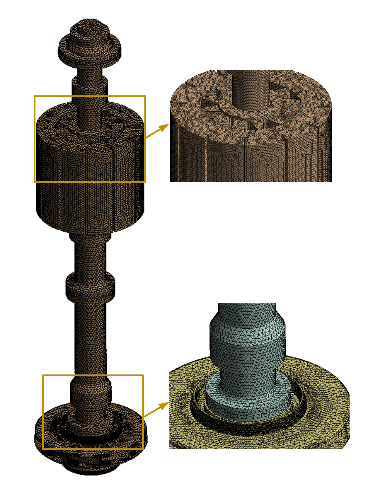
2.3. D Model and Mesh Model of the Rotor-Bearing EM System

Figure 2 shows a schematic diagram of the three-dimensional structural model of the rotor-bearing electromagnetic system (rotor system for short) of a pumped storage unit. The rotor system contains the thrust bearing, upper guide bearing, generator rotor, lower guide bearing, water guide bearing, and runner structure. The unit is arranged in a semi-parachute configuration, the total length of the rotor system shaft system is about 18.5 m, the rated speed of the unit is 500 r·min−1 and the flyaway speed is 632.1 r·min−1.
It is assumed that the generator rotor and turbine runner are not deformed during the operation of the unit, while the effect of the torsional action of the main shaft is ignored and the influence of the mass of the rotor shaft and the thrust bearing on the vibration state of the unit system is not considered. The supporting effects of the upper guide bearing, lower guide bearing, water guide bearing, and thrust bearing on the rotor system are modeled separately using the bearing unit as the boundary condition and assuming that the rotating parts are rigid. To simplify the calculations, only the direct stiffness of the oil film is considered, without taking into account the cross stiffness and torsional stiffness. The effect of unbalanced magnetic pull on the shaft system due to uneven gaps between the generator rotor and stator is modeled using a bearing unit with a negative stiffness factor as a boundary condition. The material properties of the rotor system components are shown in Table 2.
Figure 3 shows the three-dimensional structural mesh model of the rotor system of the pumped storage unit. The structure of the rotor system is complex. A structured mesh is used for the circumferentially distributed structure in the rotor system, and an unstructured mesh is used for the non-peripherally distributed structure, and the mesh is encrypted and adjusted for the small structural surfaces in the rotor system in order to ensure the quality of the mesh and the accuracy of the mesh node connections in the area of structural dimensional changes and localities.
In order to ensure the accuracy of the numerical calculation results and to save computer resources [24], this article takes the calculated value of the inherent frequency of the rotor system modal analysis as the target, and verifies that the change rate of the first three orders of the inherent frequency of the modal of the rotor system is less than 3% for different numbers of rotor system grid models, and finally chooses a rotor system calculation model with a grid number of 4.92 × 10⁶. The grid-independent verification results are shown in Figure 4.

3. Analysis of Unbalanced Magnetic Pull on the Rotor of a Pumped Storage Unit Generator

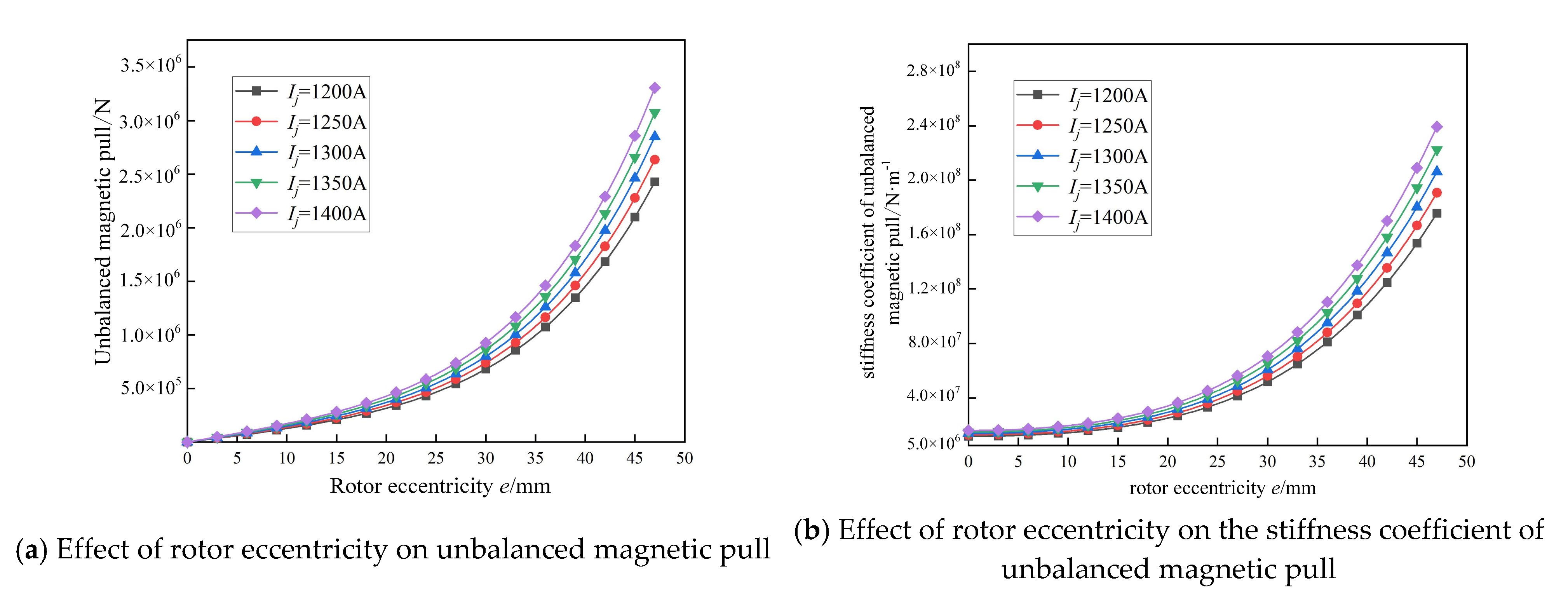
3.1. Effect of Rotor Eccentricity on Unbalanced Magnetic Pull

Figure 5a shows the effect of rotor eccentricity on the unbalanced magnetic pull of the generator rotor in a pumped storage power station. The rotor eccentricity is a typical manifestation of unit vibration, and the unbalanced magnetic pull force non-linearity of the unit under different vibration conditions is the key research object of rotor system modal analysis. As the eccentricity of the generator rotor increases, the unbalanced magnetic pull shows a non-linear trend to increase. When e < 20 mm, the unbalance magnetic pull increases mainly linearly; when e > 20 mm, the unbalance magnetic pull non-linearly increases significantly, and when the eccentricity distance reaches the maximum distance (47 mm), the unbalance magnetic pull reaches its maximum value. At the same time, the excitation current also has an influence on the unbalanced magnetic pull of the rotor, which increases gradually with the increase of the excitation current. When e = 3 mm, the increase in the unbalanced magnetic pull of the rotor from 1200 A to 1400 A is 1.28 × 10⁴ N, when e = 47 mm, the increase in the unbalanced magnetic pull of the rotor from 1200 A to 1400 A is 8.77 × 10⁵ N, and the ratio of the increase in unbalanced magnetic pull under two rotor eccentric distances reaches 68.51, so the increase in the unbalanced magnetic pull of the rotor due to the increase in unbalanced rotor pull, which in turn is due to the excitation current, gradually increases with increasing eccentricity.
Figure 5b shows the effect of rotor eccentricity on the unbalanced magnetic pull stiffness coefficient of the generator rotor in a pumped storage power station. The larger the rotor eccentricity, the more obvious the non-linear increase in the unbalance magnetic pull stiffness coefficient. When e < 15 mm, the unbalanced magnetic pull stiffness coefficient mainly increases gradually in a linear trend, with a small increase, and the excitation current has less influence on the increase in the unbalanced magnetic pull stiffness coefficient. When e >15 mm, the unbalanced magnetic pull stiffness coefficient mainly increases gradually in a non-linear trend, with a larger increase, and the rotor eccentricity has a greater influence on the unbalanced magnetic pull stiffness coefficient. When e = 3 mm, the increase in the unbalanced magnetic pull stiffness coefficient of the rotor from 1200 A to 1400 A is 4.35 × 10⁶, and when e = 47 mm, the increase in the unbalanced magnetic pull stiffness coefficient of the rotor from 1200 A to 1400 A is 6.35 × 10⁷. The increase in the unbalanced magnetic pull stiffness coefficient of the two rotor eccentric distances reaches 14.54.

3.2. Influence of Bearing Stiffness on Critical Speed

By adjusting the clearance between the upper and lower guide bearing blocks and the path of the generator to change the bearing preload coefficient, the dynamic characteristics of the guide bearings are changed and the vibration amplitude of the shaft system is controlled to ensure the safe and stable operation of the unit. Therefore, it is of practical significance to analyze the influence of each guide-bearing stiffness change on the dynamic characteristics of the shaft system.
The rotor system has its own inherent frequency f. When the rotor rotates at a frequency close to or equal to its inherent frequency, the rotor system will vibrate violently, and the speed at this time is called the critical speed ni. The inherent frequency of the rotor system is related to the mass, stiffness, and damping of the rotor system, and the finite element method can be used to obtain the calculation of the inherent frequency and critical speed of the rotor system itself [25].
Expression for critical speed:
n i = 60 ω i / 2 π
Inherent frequency expressions:
f i = ω i / 2 π
Expressions for inherent frequency and critical speed:
n i = 60 f i
where ω is the rotor system rotational angular velocity and i is the number of orders.
The effect of changes in the upper guide bearing, lower guide bearing, and water guide bearing stiffness coefficients on the critical speed of the system is shown in Figure 6. In order to study the influence of the guide bearing stiffness on the critical speed of the unit’s shaft system, the axial and torsional stiffnesses of the thrust bearing were first determined to be 2.5 × 10⁹ N/m and 2 × 10¹⁰ N·m/r, respectively, and the critical speeds of the shaft system were calculated when the upper, lower, and water guide bearing stiffnesses were fixed at 2.0 × 10⁹ N/m, 2.0 × 10⁹ N/m, and 1.5 × 10⁹ N/m, respectively, and then the critical speeds of the shaft system were then calculated when the individual bearing stiffness is increased or decreased by 25%, 50%, and 75%, respectively, to obtain the effect of the change in bearing stiffness on the critical speed of the unit’s shaft system.
The change in the stiffness coefficients of the upper guide bearing, lower guide bearing, and water guide bearing all have an obvious influence on the critical speed of each stage of the rotor system, the critical speed of the first stage of the unit rotor system is 0rpm. The change in the upper guide bearing stiffness coefficient and the critical speed of each stage show a trend of increasing step by step; the critical speed of the third and fourth stages is most affected by the change in the upper guide bearing stiffness coefficient, and the critical speed of the rotor system of the second, fifth, and sixth stages basically does not change significantly. When the upper guide bearing stiffness coefficient is greater than 2.0 × 10⁹ N/m, the critical speed of the rotor system remains basically unchanged at all stages. As the stiffness coefficient of the lower guide bearing increases from 5.0 × 10⁸ N/m to 3.5 × 10⁹ N/m, the critical speed of the rotor system increases significantly in the third, fourth, seventh, eighth, tenth, and eleventh steps, and the critical speeds of the third and fourth steps are most affected by the change in the stiffness coefficient of the lower guide bearing. When the lower guide bearing stiffness coefficient is greater than 2.0 × 10⁹ N/m, the increase in critical speed of each stage of the rotor system remains within 2%, and the effect of increasing the bearing stiffness coefficient on the increase in critical speed of each stage of the rotor system is not obvious. The increase in the water-guided bearing stiffness factor from 3.75 × 10⁸ N/m to 2.625 × 10⁹ N/m increases the third-, fourth-, fifth-, sixth-, tenth-, and eleventh-order critical speeds of the rotor system, with the third- and fourth-order critical speeds increasing significantly, while the second-, seventh-, and eighth-order critical speeds are basically unaffected by the change in the water-guided bearing stiffness factor. When the water-guided bearing stiffness coefficient is greater than 1.5 × 10⁹ N/m, the increase in the critical speed of the rotor system at each stage is less than 1%, so the change in the water-guided bearing stiffness coefficient no longer significantly changes the critical speed of the rotor system.
In summary, through the numerical calculation of different guide bearings of the pumped storage unit rotor system by the orthogonal test method, the distribution of the dynamic characteristics of the unit rotor system is finally obtained, the minimum bearing stiffness coefficients of different guide bearings are obtained, and the influence of different guide bearings on the critical speed of the unit rotor system is investigated.

3.3. Effect of Unbalanced Magnetic Pull on the Dynamic Characteristics of Rotor Systems

Based on the previous calculations, the magnetic tension stiffness coefficients were taken to be −1.459 × 10⁷ N/m (rotor eccentricity e of 5 mm), −2.157 × 10⁷ N/m (rotor eccentricity e of 15 mm), and −2 × 10⁸ N/m (rotor eccentricity e of 46.5 mm), and then the critical rotor system speeds were calculated considering and not considering magnetic tension, respectively. The transverse stiffness coefficients of the upper, lower, and water-guided bearings were taken as 2.0 × 10⁹ N/m, 2.0 × 10⁹ N/m, and 1.5 × 10⁹ N/m, respectively; the vertical stiffness coefficient of the thrust bearing was taken as 2.5 × 10⁹ N/m; and the torsional stiffness coefficient was taken as 2.0 × 10⁹ N·m/r.
The effect of unbalanced magnetic pull on the dynamic characteristics of the rotor system is shown in Table 3. Since turbine units are generally designed to be rigid, requiring a flyaway speed below the first-order critical speed, considering the effect of magnetic pull will result in a safer design of the shaft system. The rated speed of the rotor system is 500 r·min−1 (i.e., the rotational frequency is 8.334 Hz), and the flyaway speed is 632.1 r·min−1 (i.e., the rotational frequency is 10.535 Hz). The low-order mode inherent frequencies of different vibration types of the rotor system are analyzed, and the unbalanced magnetic pull reduces the axial first-order mode’s inherent frequency by 23.86% and has less influence on the axial second-order mode inherent frequency. The unbalanced magnetic tension reduces the axial first-order mode inherent frequency by 23.86%, while it has less effect on the axial second-order mode inherent frequency by only 1.25%, and the rotor eccentricity has no effect on the axial first-order mode inherent frequency. As the unbalanced magnetic pull acts on the rotor surface of the generator, it has an effect on the inherent frequency of the rotor transverse oscillation in a certain order of vibration. The unbalanced magnetic tension has a large impact on the rotor system’s transverse first-order modal vibration inherent frequency; the inherent frequency amplitude drop reaches 34.65%, and the first-order inherent frequency is 7.82 Hz, which is lower than the unit rotation frequency. The unit may produce a strong vibration phenomenon in the process of increasing the load. The third-order inherent frequency drop is 6%–10%, and the second-order inherent frequency is almost unaffected. The unbalanced magnetic pull has less influence on the rotor system’s torsional inherent frequency, the first three orders of the modal inherent frequency drop are within 2%, and the torsional inherent frequency is much larger than the unit flyaway rotation frequency, so the torsional inherent frequency will not affect the dynamic characteristics of the rotor system.
The modal vibration pattern of a rotor system reflects the ratio of the relative displacements of the degrees of freedom of the structure at each order of the modal state. In this study, a rotor system modal shape considering unbalanced magnetic tension (magnetic tension stiffness factor of −2 × 10⁸ N/m) was selected for analysis. Figure 7 shows the low-order modal vibration pattern of the rotor system; the transparent area is the undeformed model of the rotor system, and the colored area is the deformed model of the rotor system. The axial first-order modal vibration model shows the overall rigid up and down movement of the rotor system, while the second-order modal vibration model shows the axial expansion and contraction movement of the generator rotor and turbine runner, and the displacement amplitude of the runner is larger. The transverse first-order mode is mainly characterized by the transverse oscillation of the runner, with the largest displacement values occurring in the runner structure and the generator rotor being almost stationary. The second- and third-order modes are characterized by the reverse oscillation of the runner and generator rotor, with the largest second-order-mode displacement values occurring in the runner structure and the largest third-order-mode displacement values occurring in the generator rotor structure. The torsional first-, second-, and third-order modal oscillations are manifested by the torsion of the pump turbine runner, the torsion of the generator rotor, and the torsion of the coupling below the main shaft guide bearing, with the oscillations becoming larger or smaller in the radial direction.

4. Conclusions

(1)
The unbalanced magnetic pull increases non-linearly with the increase in excitation current and rotor eccentricity. During stable operation, the generator rotor vibration oscillation is small and the unbalance magnetic pull increases linearly. During the transition process, excessive rotor vibration may cause the rotor eccentricity to increase, and the unbalance magnetic pull increases with an obvious non-linear trend.
(2)
Changes in the stiffness coefficients of the upper guide bearing, lower guide bearing, and water guide bearing all have a significant effect on the critical speed of the rotor system at each stage. Changes in the stiffness coefficients of the three guide bearings have the greatest effect on the critical speed of the rotor system at the third and fourth stages, and the minimum bearing stiffness coefficients for stable operation of the different guide bearings of the rotor system are obtained.
(3)
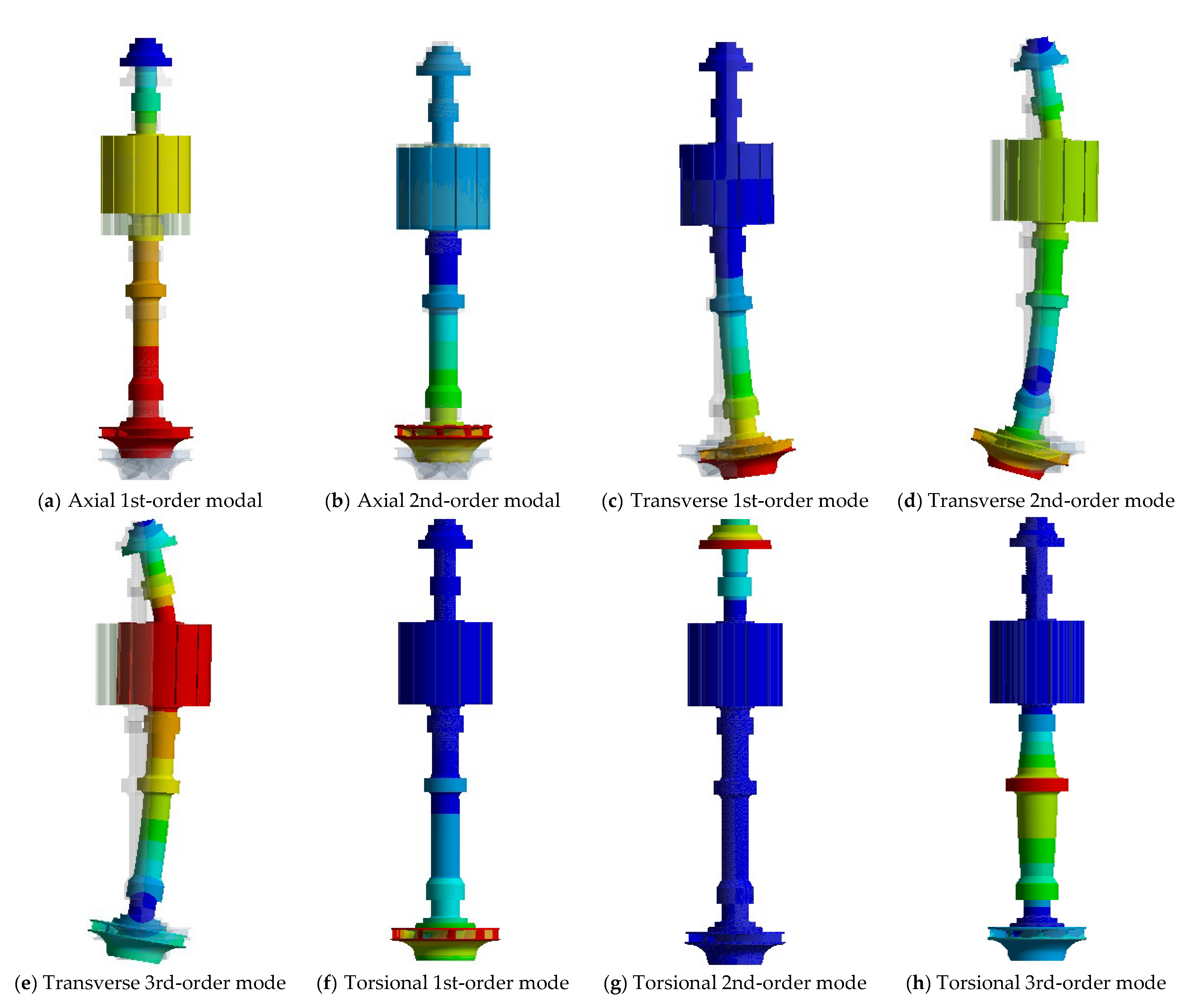
The unbalanced magnetic tension has an impact on the intrinsic frequency of transverse oscillation in the first-order mode vibration pattern, with the intrinsic frequency amplitude dropping by 34.65%, which is lower than the rotational frequency of the unit, and strong vibration may occur during the unit load increase. The axial mode vibration pattern is characterized by up and down movements of different parts of the rotor system, the transverse mode vibration pattern is characterized by transverse oscillations of different parts, and the torsional mode is characterized by the radial enlargement or reduction in the generator rotor, runner, and coupling parts of the rotor system.

Author Contributions

W.W., J.P., W.Z., L.Z. and Z.W. proposed the simulation method. J.P., W.Z., X.L. and Z.L. completed the numerical simulations. W.W., J.P., W.Z. and D.Y. analyzed the data and wrote the paper. J.P. and Z.W. revised and reviewed the paper. W.W., X.L. and Z.L. provided some data support for the study. All authors have read and agreed to the published version of the manuscript.

Funding

This research was funded by Evaluation and Calculation Service for the Coupling Performance of the Shaft System of Pump-turbine Unit in Luoning Pumped Storage Power Station of State Grid Xinyuan Group Co., Ltd. (approval No. 20222001266).

Data Availability Statement

Not applicable.

Acknowledgments

This research is especially grateful to the State Grid Xinyuan Group Co., Ltd. for the funding of the science and technology project, and to Tsinghua University and China Agricultural University for their strong support in the theoretical research of the project.

Conflicts of Interest

W.W. and other co-authors have no conflict of interest.

References

  1. Feng, F.; Chu, F.; Zhang, Z.; Li, C. Analysis and Calculation of Dynamic Characteristics of the Shaft System of a Hydro-Turbine Generator Unit. J. Vib. Meas. Diagn. 1999, 3–9+68. [Google Scholar] [CrossRef]
  2. Zhai, L.; Yao, Z.; Huang, Q.; Yan, Z.; Wang, Z. 3D Dynamic Characteristics of Rotor System of Pump Storage Generator Set. Trans. Chin. Soc. Agric. Mach. 2014, 45, 107–111+137. [Google Scholar]
  3. Wang, T.; Wang, F. Critical Speeds and Vibration Modes of Shafting for High-Speed Permanent-Magnet Machines. Eng. Mech. 2012, 29, 264–269. [Google Scholar]
  4. Wang, Z.; Yu, J.; Fang, Y.; Wen, X.; Cao, J.; Shi, Q. The characteristic analysis of rotor dynamics of large hydraulic generating uint. J. Hydroelectr. Eng. 2005, 4, 62–66. [Google Scholar]
  5. Tenhunen, T.P.; Holopainen, A.A. Spatial linearity of an unbalanced magnetic pull in induction motors during eccentric rotor motions. COMPEL Int. J. Comput. Math. Electr. Electron. Eng. 2003, 22, 862–876. [Google Scholar] [CrossRef] [Green Version]
  6. Holopainen, T.P.; Tenhunen, A.; Lantto, E.; Arkkio, A. Unbalanced magnetic pull induced by arbitrary eccentric motion of cage rotor in transient operation. Part 1: Analytical model. Electr. Eng. 2005, 88, 13–24. [Google Scholar] [CrossRef]
  7. Holopainen, T.P.; Tenhunen, A.; Lantto, E.; Arkkio, A. Unbalanced magnetic pull induced by arbitrary eccentric motion of cage rotor in transient operation. Part 2: Verification and numerical parameter estimation. Electr. Eng. 2005, 88, 25–34. [Google Scholar] [CrossRef]
  8. Guo, D.; Chu, F.; Chen, D. The Unbalanced Magnetic Pull and Its Effects On Vibration In a Three-Phase Generator With Eccentric Rotor. J. Sound Vib. 2002, 254, 297–312. [Google Scholar] [CrossRef]
  9. Subbiah, R.; Rieger, N.F. On the Transient Analysis of Rotor-Bearing Systems. J. Vib. Acoust. Stress Reliab. Des. 1988, 110, 515–520. [Google Scholar] [CrossRef]
  10. Bhat RBSubbiah RSankar, T.S. Dynamic Behavior of a Simple Rotor with Dissimilar Hydrodynamic Bearings by Modal Analysis. J. Vib. Acoust. Stress Reliab. Des. 1985, 107, 267–269. [Google Scholar] [CrossRef]
  11. Subbiah RBhat RBSankar, T.S. Response of Rotors Subjected to Random Support Excitations. J. Vib. Acoust. Stress Reliab. Des. 1985, 107, 453–459. [Google Scholar] [CrossRef]
  12. Wang, T.; Wang, F.; Bai, H.; Cui, H. Stiffness and Critical Speed Calculation of Magnetic Bearing-rotor System Based on FEA. In Proceedings of the 11th International Conference on Electrical Machines and Systems, Wuhan, China, 17–20 October 2008; Volume 2, pp. 75–78. [Google Scholar]
  13. Wei, F.; Zhang, K.; Liu, Z.; Liu, B.; Zhang, H.; Mei, J.; Wu, L. Modeling and analysis of unbalanced magnetic pull in synchronous motorized spindle considering magneto-thermal coupling. Int. J. Appl. Electromagn. Mech. 2022, 70, 303–321. [Google Scholar]
  14. Ma, C.; Zhao, D.; Liao, W.; Sun, W.; Guo, P.; Xu, Y. Effect of the unbalanced magnetic pull force and oil-film force on nonlinearity of a dual-rotor bearing system. Proc. Inst. Mech. Eng. Part K: J. Multi-Body Dyn. 2022, 236, 623–638. [Google Scholar] [CrossRef]
  15. Huang, L.; Shen, G.; Hu, N.; Chen, L.; Yang, Y. Coupled Electromagnetic-Dynamic Modeling and Bearing Fault Characteristics of Induction Motors considering Unbalanced Magnetic Pull. Entropy 2022, 24, 1386. [Google Scholar] [CrossRef]
  16. Zhang, L.; Ma, Z.; Song, B. Characteristics Analysis of Hydroelectric Generating Set under Unbalanced Magnetic Pull and Sealing Force of Runner. Water Resour. Power 2010, 28, 117–120. [Google Scholar]
  17. Song, Z.; Ma, Z. Nonlinear vibration analysis of an eccentric rotor with unbalance magnetic pull. J. Vib. Shock 2010, 29, 169–173+250. [Google Scholar] [CrossRef]
  18. Perers, R.; Lundin, U.; Leijon, M. Saturation Effects on Unbalanced Magnetic Pull in a Hydroelectric Generator With an Eccentric Rotor. IEEE Trans. Magn. 2007, 43, 3884–3890. [Google Scholar] [CrossRef]
  19. Perers, R.; Lundin, U.; Leijon, M. Development of synchronous generators for Swedish hydropower: A review. Renew. Sustain. Energy Rev. 2005, 11, 1008–1017. [Google Scholar] [CrossRef]
  20. Wallin, M.; Lundin, U. Dynamic Unbalanced Pull from Field Winding Turn Short Circuits in Hydropower Generators. Electr. Power Compon. Syst. 2013, 41, 1672–1685. [Google Scholar] [CrossRef]
  21. Wallin, M.; Bladh, J.; Lundin, U. Damper Winding Influence on Unbalanced Magnetic Pull in Salient Pole Generators With Rotor Eccentricity. IEEE Trans. Magn. 2013, 49, 5158–5165. [Google Scholar] [CrossRef]
  22. Wallin, M.; Ranlof, M.; Lundin, U. Reduction of Unbalanced Magnetic Pull in Synchronous Machines due to Parallel Circuits. IEEE Trans. Magn. 2011, 47, 4827–4833. [Google Scholar] [CrossRef]
  23. Nave, O.; Sharma, M. Singular Perturbed Vector Field (SPVF) Applied to Complex ODE System with Hidden Hierarchy Application to Turbocharger Engine Model. Int. J. Nonlinear Sci. Numer. Simul. 2020, 21, 99–113. [Google Scholar] [CrossRef]
  24. Pang, J.; Liu, H.; Liu, X.; Yang, H.; Peng, Y.; Zeng, Y.; Yu, Z. Study on sediment erosion of high head Francis turbine runner in Minjiang River basin. Renew. Energy 2022, 192, 849–858. [Google Scholar] [CrossRef]
  25. Shi, D. Calculation of UMP and Analysis of Rotor Dynamic Characteristics of Large Induction Motor; Harbin University of Science and Technology: Harbin, China, 2016. [Google Scholar]
Figure 1. Schematic diagram of the generator rotor eccentricity phenomenon.
Water 15 01120 g001
Figure 2. Schematic diagram of the three-dimensional structure of the rotor system.
Water 15 01120 g002
Figure 3. Three-dimensional structural mesh model of the rotor system.
Water 15 01120 g003
Figure 4. Grid-independent verification of rotor systems.
Water 15 01120 g004
Figure 5. Effect of rotor eccentricity on the magnetic pull of the rotor system.
Water 15 01120 g005
Figure 6. Effect of different stiffness factors of the three guide bearings on the critical speed of the rotor system.
Water 15 01120 g006
Figure 7. Low-order modal vibration pattern of the rotor system.
Water 15 01120 g007
Table 1. Parameters of pumped storage plants.
ParametersValuesParametersValues
Generator stator radius R0/m2.45Air gap fundamental magnetic momentum coefficient ki7
Rotor radius of generators R/m2.403Air magnetic permeability μ04π × 10−7
Rotor length of generators L/m3.665Excitation current Ij/A1200–1400
Average length of air gap δ0/m0.047Eccentric distance of generator rotor e/mm0–47
Table 2. Material properties of the rotor system components.
ComponentsMaterialsDensity/(kg/m3)Modulus of Elasticity/PaPoisson’s Ratio
CoilsCopper89001.15 × 1090.33
Magnetic yoke polesMagnetic yoke materials78302.06 × 1090.3
Othersteel78502.10 × 10110.3
Table 3. Effect of unbalanced magnetic pull on the dynamic characteristics of the rotor system.
ModalNumber of StepsNo Consideration of Unbalanced Magnetic PullConsideration of Unbalanced Magnetic Pull (e = 5 mm)Consideration of Unbalanced Magnetic Pull (e = 15 mm)Consideration of Unbalanced Magnetic Pull (e = 46.5 mm)
Values (Hz)Values (Hz)Deviation/%Values (Hz)Deviation/%Values (Hz)Deviation/%
Axial115.77812.017−23.8612.017−23.8612.017−23.86
289.32190.4371.2590.4371.2590.4371.25
Horizontal111.9667.82−34.657.82−34.657.82−34.65
216.13616.079−0.3516.064−0.4515.661−2.94
317.47716.369−6.3416.351−6.4415.886−9.10
Turning124.44324.5950.6224.5950.6224.5950.62
256.33156.6570.5856.6570.5856.6570.58
3133.04134.7701.3134.771.3134.771.3
Disclaimer/Publisher’s Note: The statements, opinions and data contained in all publications are solely those of the individual author(s) and contributor(s) and not of MDPI and/or the editor(s). MDPI and/or the editor(s) disclaim responsibility for any injury to people or property resulting from any ideas, methods, instructions or products referred to in the content.

