
Study on the Effect Mechanism of Inlet Pre-Swirl on Pressure Pulsation within a Mixed-Flow Centrifugal Pump
1
School of Civil Engineering, North Minzu University, Yinchuan 750021, China
2
Henan Key Laboratory of Water Resources Conservation and Intensive Utilization in Yellow River Basin, North China University of Water Resources and Electric Power, Zhengzhou 450046, China
3
College of Hydraulic Science and Engineering, Yangzhou University, Yangzhou 225009, China
4
Ningxia Water Resources & Hydropower Survey Design & Research Institute Co., Ltd., Yinchuan 750021, China
5
College of Water Resources, North China University of Water Resources and Electric Power, Zhengzhou 450046, China
6
College of Animal Science and Technology, Yangzhou University, Yangzhou 225009, China
*
Author to whom correspondence should be addressed.
Water 2023, 15(6), 1223; https://doi.org/10.3390/w15061223
Submission received: 1 March 2023
/
Revised: 14 March 2023
/
Accepted: 19 March 2023
/
Published: 21 March 2023
(This article belongs to the Special Issue Design and Optimization of Fluid Machinery)
Abstract
:This article explores the impact of inlet pre-swirl on pressure pulsation in a mixed-flow centrifugal pump through a combination of numerical simulations and experimental verification. Firstly, the mixed-flow centrifugal pump’s performance was initially determined through both numerical calculations and experiments. The comparison between them indicated the high accuracy of the numerical method adopted in this paper. Next, the flow pattern within the pump at various inlet pre-swirl angles was carefully compared and analyzed. It was found that positive impulse angle and inlet displacement could lead to circumferential inhomogeneity of the flow field within the impeller, while inlet pre-swirl can significantly counteract the effect of positive impulse angle. The impact of inlet pre-swirl on the flow pattern near the blade inlet will change the intensity of the secondary flow within the impeller passage. Variations in the intensity of the secondary flow can directly affect the strength of the wake and jet in the chamber. Then, the pressure pulsations within the chamber were compared and analyzed for various inlet pre-swirl angles. The results revealed that as the inlet pre-swirl angle increased, the intensity of pressure pulsation decreased significantly. This discovery sheds light on the influence mechanism of inlet pre-swirl on pressure pulsation within mixed-flow pumps, potentially serving as a theoretical foundation for enhancing the operational stability of mixed-flow centrifugal pumps.
1. Introduction
Mixed-flow centrifugal pumps are extensively utilized in various domains, such as water conservancy projects, urban water supply, and industrial production, due to their high design flow and efficiency [1,2,3]. As the utilization of mixed-flow centrifugal pumps continues to expand, various factors that impact their operational stability have become a prominent research subject for scholars [4,5]. Recently, numerous studies have shown that the pre-swirl characteristics can greatly affect the performance and operational stability of mixed-flow centrifugal pumps [6]. Based on theoretical derivation, Predin [7] first discovered the existence of vortices at the front end of a rotating impeller and defined it as an inlet pre-swirl phenomenon. Figurella [8] et al. performed performance tests on a mixed-flow centrifugal pump with varying inlet pre-rotation angles, highlighting the effect of pre-rotation on pump performance. In another study, Liu [9] conducted a performance test on a centrifugal pump with a front inflow tube capable of producing pre-rotation with different strengths. These studies indicated that appropriate inlet pre-swirl with a positive pre-swirl angle could reduce the shaft power of the centrifugal pump and enhance its hydraulic efficiency. Building on this research, Tan et al. [10] examined the influence of inlet pre-swirl on the hydraulic design schemes of centrifugal pumps and developed adjustment strategies for hydraulic design in the presence of inlet pre-swirl. Additionally, Tan et al. [11] explored the effect of inlet pre-swirl on the cavitation performance of centrifugal pumps, identifying a method for optimizing cavitation performance by adjusting the front guide vane. In recent years, it has become a more common method to enhance the performance of centrifugal pumps by the inlet precession provided by the front guide vane [12,13]. Therefore, investigating the change in performance and operational stability of mixed-flow centrifugal pumps with inlet pre-swirl is of immense importance.
Pressure pulsation is a common unsteady phenomenon during the operation of turbomachinery. Its main source is the periodic coupling between the stator and the rotor [14]. The presence of pressure pulsations inevitably has a detrimental effect on the operation of turbomachinery and needs to be suppressed using appropriate measures. Based on a simplified numerical model of the centrifugal stage of a compressor, Carretta et al. [15] effectively evaluated the stability limits of the centrifugal stage by means of a limiting mass flow rate prediction method, which provides an important methodological guide for optimizing the design of the centrifugal stage for stability. At the same time, pressure pulsation, as a direct manifestation of dynamic interference, is also an important parameter characterizing the intensity of the pump operation instability. According to existing studies, the pressure pulsation characteristics of mixed-flow centrifugal pumps are sensitive to changes in pump geometry, operating conditions, and other factors. Among them, Gonzalez [16] was the first to carry out experiments on the unsteady flow within centrifugal pumps and found that pressure pulsation is an important cause of vibration to pump systems, proving that the intensity of pressure pulsation can characterize the operational instability of pumps. Meanwhile, Yang et al. [17] measured the external field noise of a centrifugal pump considering pressure pulsation as the energy source and confirmed that pressure pulsation not only triggers pump vibration, but also a cause of noise produced by the pump system. Building on this, the researchers attempted to reduce the magnitude of pressure pulsation within the centrifugal pump by adjusting the geometry parameters, thereby reducing the vibration and noise intensity of the pump system and improving its operational stability. Li et al. [18] found that the size of rotor–stator clearance has an extremely obvious effect on the dynamic–static interference strength of mixed-flow centrifugal pumps, and a small increase of rotor–stator clearance could significantly reduce the strength of pressure pulsation. In this regard, Dong [19] proposed an optimization scheme for the geometric parameters of the dynamic–static interference zones to reduce the flow noise due to pressure pulsation. Zheng [20] et al. deeply studied the self characteristics of pressure pulsation within the pump and found that the main frequency of pressure pulsation changes at different flow conditions; the intensity of the pump operating instability varies at different flow rates. Yang et al. [21,22] investigated the pressure pulsation characteristics within a multi-stage mixed flow pump by Fourier transform and wavelet transform, analyzed the pulsation interference and coupling between stages, and determined the existence of inter-stage propagation phenomenon of pressure pulsation. Easily seen, the current research on pressure pulsation in mixed-flow centrifugal pumps primarily concentrates on analyzing the pressure pulsation, as well as the vibration and noise it produces. The option of suppressing the pressure pulsation within the pump by adjusting the pump geometry parameters has also been explored. However, the inlet flow of mixed-flow pumps is affected by the environment and often has a pre-swirl characteristic. There are very few studies on the unsteady flow within mixed flow pumps with inlet pre-swirl. The studies that exist do not involve the study of mechanical effects of inlet pre-swirl on the intensity of pressure pulsation.
The purpose of this paper is to explore the mechanistic impact of variations in the inlet pre-swirl angle on the generation and intensity of pressure pulsations in mixed-flow centrifugal pumps using numerical simulations and experimental validation. This investigation aims to establish a theoretical foundation for the hydraulic optimization and enhancement of operational stability for mixed-flow pumps by taking into account the inlet pre-swirl.
2. Geometry and Parameters
A typical mixed-flow centrifugal pump, 300QJ200, is investigated in this paper: 300 indicates that the maximum outer diameter of the pump body is 300 mm; QJ represents that it can be submerged in water; and 200 represents its rated design flow rate, Qdes = 200 m3/h. The rated design speed of this mixed-flow centrifugal pump is ndes = 2900 r/min, and the rated design head is Hdes = 22.5 m. Therefore, the design specific speed of this mixed-flow centrifugal pump is
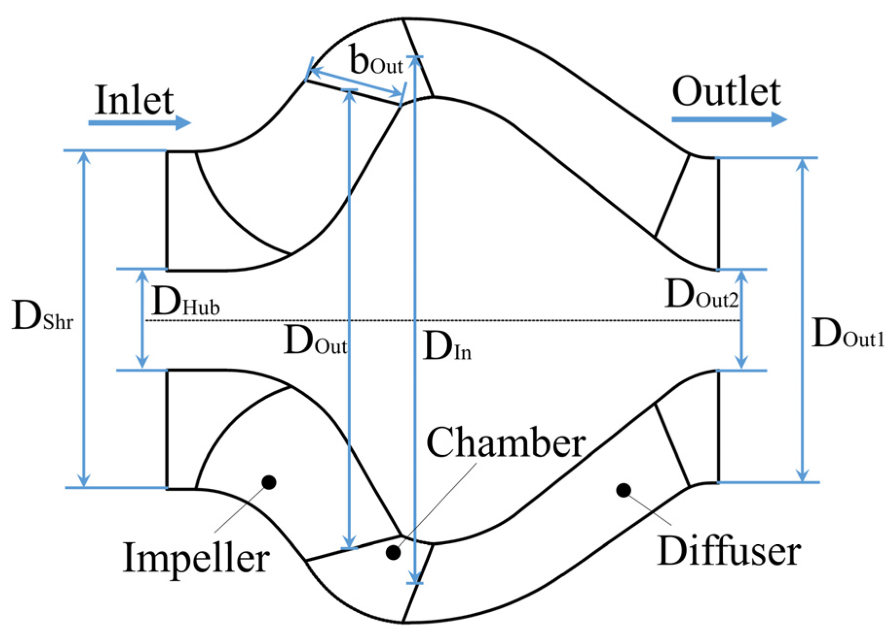
The blade number of the impeller and the diffuser of this mixed flow pump are 6 and 7, respectively. The number of blades on the impeller and diffuser significantly affects the pressure pulsation characteristics within the pump, as previous research has shown [23]. When the blade numbers of the impeller and the diffuser have mutual quality, the pressure pulsation within the impeller and diffuser does not easily occur, due to the pat vibration phenomenon. In turn, to avoid the pump vibration caused by this phenomenon, a space-guided diffuser is adopted as the spiral housing of this pump. This is the same as most mixed flow pumps. Consequently, the research findings presented in this paper can be applied to a wide range of mixed flow pump models. Figure 1 displays the primary dimensions of the mixed-flow pump model, and Table 1 details the principal geometric parameters marked in Figure 1.
3. Numerical Modeling
3.1. Model Building
At the beginning of this study, it is necessary to create a 3D model of the mixed-flow pump and other subdomains encompassed within the computational domain. NX UG software was utilized for this task. The primary hydraulic components of the mixed-flow pump, which consist of the impeller, diffuser, and chamber between them, were modeled, along with the inlet and outlet sections representing other subdomains. Among them, the blades of the impeller and the diffuser are space twisted structures. Therefore, the modeling of them needs to follow the process of “point to surface, surface to body”. The inlet section and the outlet section are simplified as straight pipes. The length of the inlet section was set to 0.5 times the impeller inlet diameter to ensure that the pre-swirl setting would not decay within the inlet section. It is also ensured that flow characteristics such as backflow can be captured. The length of the outlet section, on the other hand, is equal to 10 times the impeller inlet diameter to provide enough evolution space for the subsequent flow and improve the convergence of the numerical simulation.
3.2. Governing Equations and Boundary Conditions
Turbulence models are used to describe the turbulent phenomena generated by fluids flowing at high velocities, and their accuracy and applicability have a crucial impact on the accuracy and reliability of numerical simulation results. The numerical simulation work in this study is based on the shear stress transport (SST) turbulence model. The SST turbulence model combines the k-ε and k-ω models to increase the adaptability of the model, while retaining its accuracy in solving unsteady flows such as large curvature flows and separated flows. The transport equations for turbulent kinetic energy k and turbulent frequency ω are as follows [24]:
The turbulent viscosity vt is given by the following equation:
The blending functions F1 and F2 are calculated as
where S is the vorticity; y is the near-wall distance. The values of the relevant constants are: a1 = 0.31, σk = 0.85, σω = 0.5, β = 0.075, β* = 0.09.
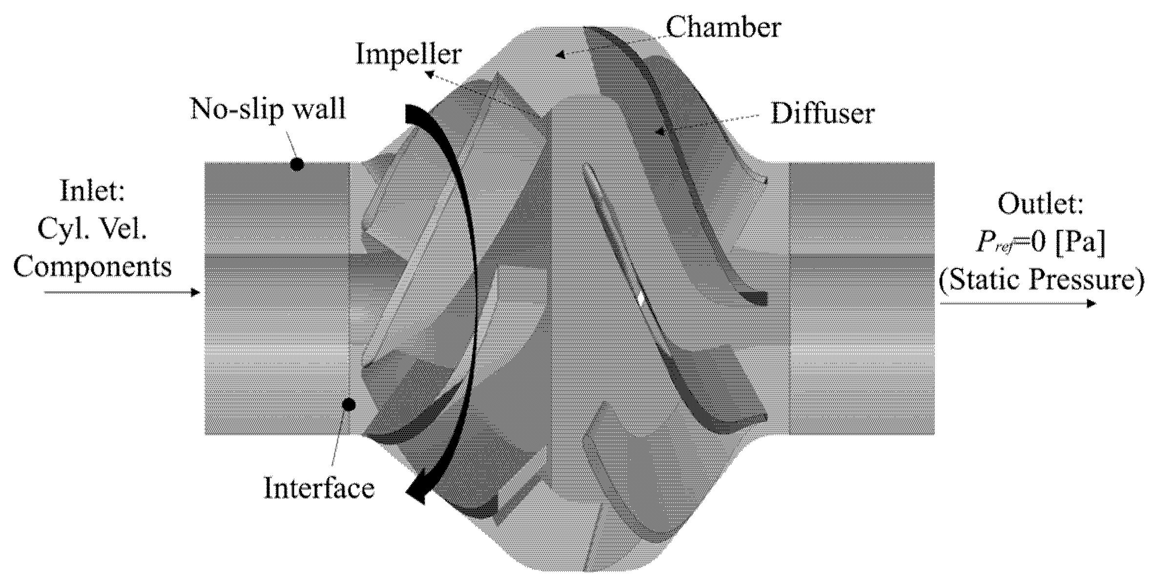
The numerical simulations for this study are completed in ANSYS CFX and the calculation sub-domains are connected by interfaces to form the complete calculation domain. In this case, the impeller is coupled to the adjacent calculation sub-domain using frozen-rotor and the grid is connected using the general grid interface (GGI) method. The solid wall within the calculation domain is set as a no-slip wall. In order to achieve adjustable inlet pre-swirl angle, Cyl. Vel. Components is adopted at inlet position of the computational domain. Firstly, the inlet velocity triangle is determined according to the magnitude of the pre-rotation angle. Then, the three components of the inlet velocity are determined separately: axial component, radial component and theta component. The outlet is set to static pressure and the initial value is 0 Pa, as shown in Figure 2. Due to the need to study the pressure pulsations in the pump chamber, this study also requires transient numerical calculations based on the results of the steady numerical calculations. The time step for the transient calculation is set to the time taken for the impeller to turn through 3°, i.e., 1.73 × 10⁻⁴ s. The roughness of the solid wall surface in the calculation domain is set to 10 μm, as appropriate for this case. In addition, the isothermal condition is chosen for the heat transfer model, with the residual target set to 10−5 and the discrete format set to second order. It is worth noting that ω-based low Reynolds number turbulence models usually require a very high quality boundary layer mesh at walls (y+ < 2). Taking into account the reasonable allocation of computational resources and the need for accuracy in capturing the boundary layer flow for this numerical calculation, the automatic wall function is enabled to handle the boundary layer flow.
3.3. Grid and Irrelevance Analysis
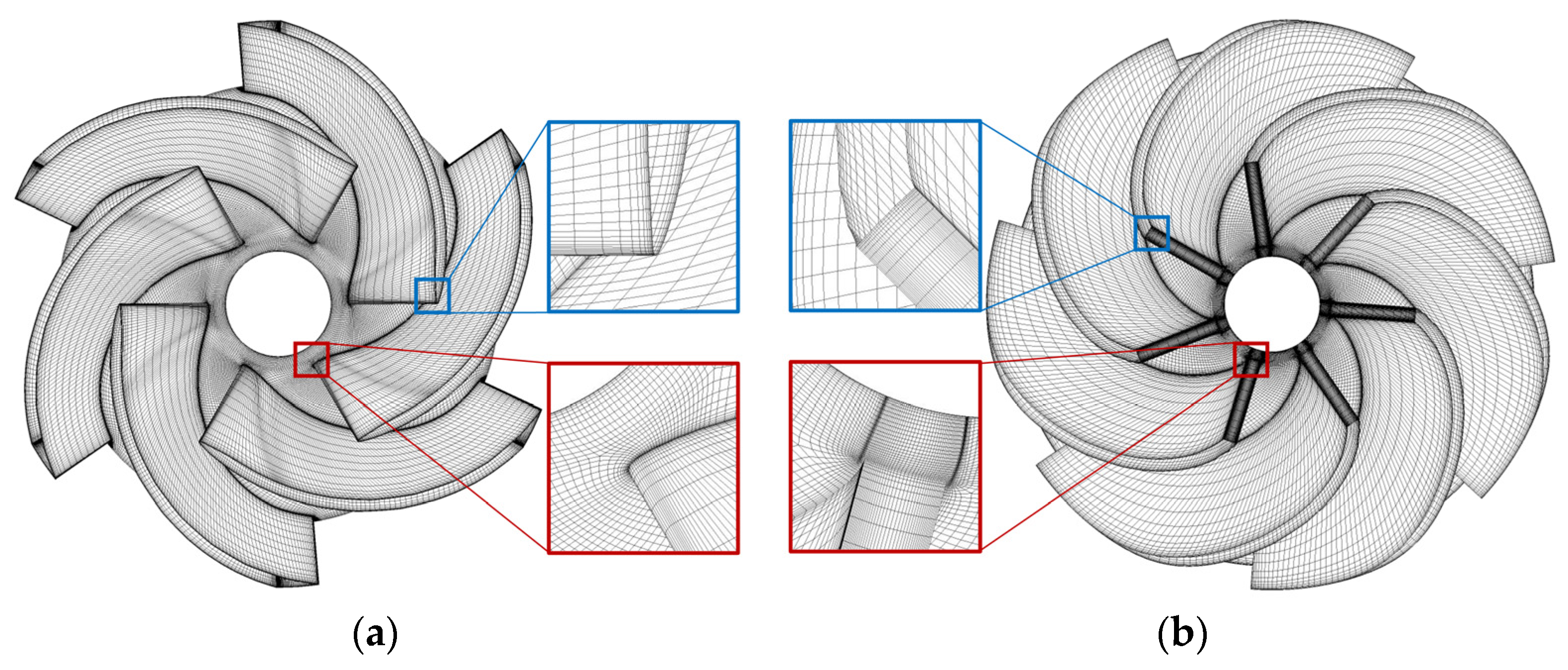
For an identical computational domain, the hexahedral structure mesh can ensure the accuracy of the numerical simulation and reduce the total number of meshes at the same time (compared with tetrahedral meshes), possibly shortening the cycle time of the numerical simulation. Thus, the computational domains in this paper are all topologized with hexahedral meshes. Among them, the meshes of the impeller and diffuser are generated by Turbogrid software, and the mesh details of both are shown in Figure 3. It is worth noting that the near-wall mesh is locally encrypted to facilitate capturing the details of the flow within the model. The overall y+ of the mesh was controlled to be between 50 and 200, in line with the basic requirements for automatic wall function processing. The meshes of the inlet/outlet sections and the chamber are generated by ANSYS ICEM software. This paper also examines how the accuracy of numerical results is affected by the grid number, which is achieved by controlling the global maximum grid size. This process takes the head and efficiency of the mixed-flow centrifugal pump as the dependent variables and observes the change pattern of the dependent variables by adjusting the global maximum grid size, as shown in Table 2. Observably, when the global maximum grid size is equal to or less than 1.8 mm, the numerical predictions exhibit fluctuations of less than 0.3% for both head and efficiency. As a result, a global maximum grid size of 1.8 mm is adopted for the research.
3.4. Monitoring Points Arrangement
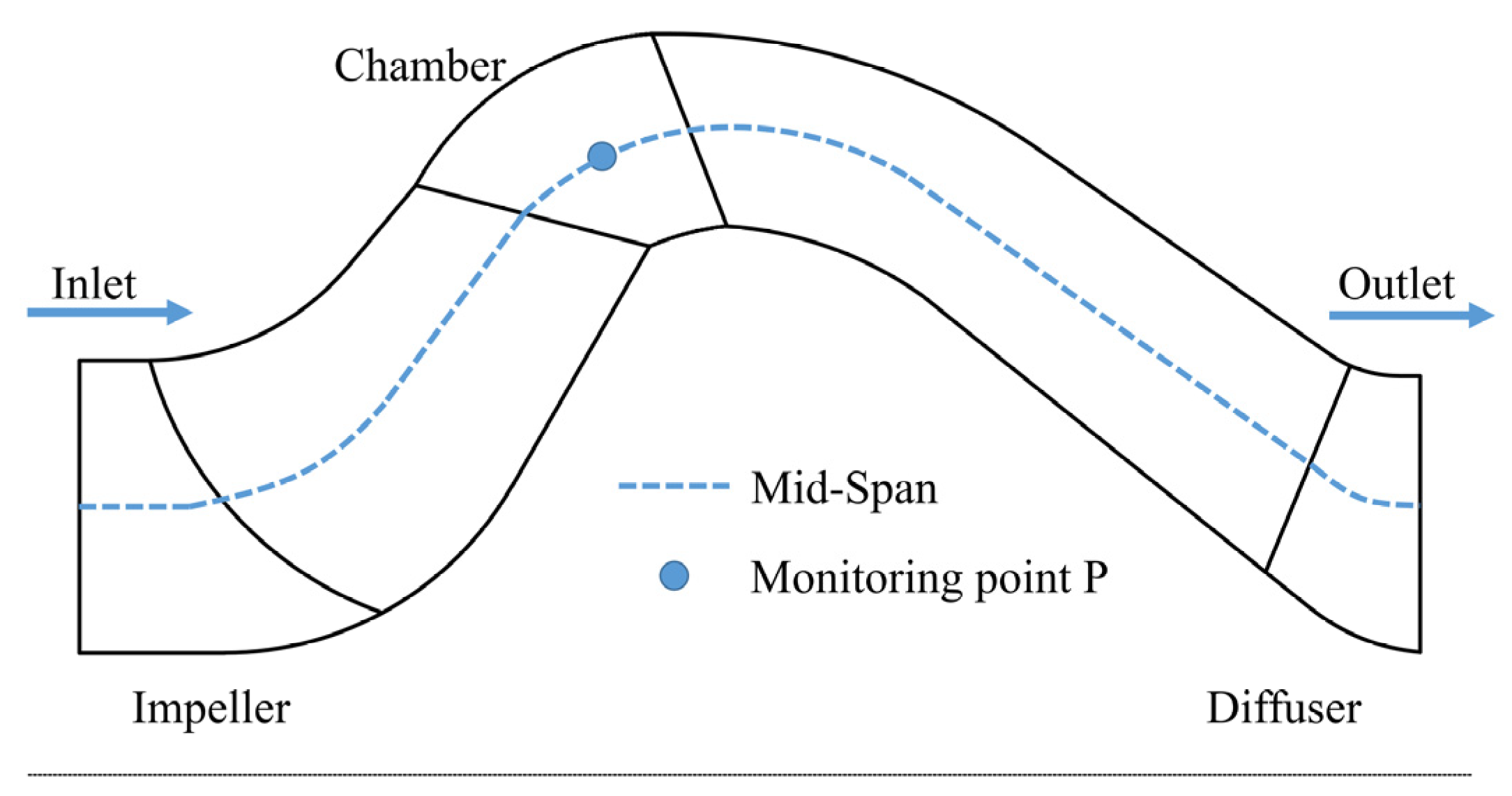
Since the chamber sub-domain has the highest intensity of dynamic–static interference, the strongest pressure pulsation signal is found in this region, and it fully encompasses all the pressure pulsation characteristics within the pump. Therefore, the monitoring point is chosen as the P-point at the mid-span position in the chamber in this paper. The same distance is maintained from point P on the mid-span to the impeller and diffuser, so that the data at this point can reflect the influence of both impeller and diffuser on the pressure pulsation characteristics. The location of monitoring point P is shown in Figure 4.
4. Results and Discussion
4.1. Pump Performance Validation
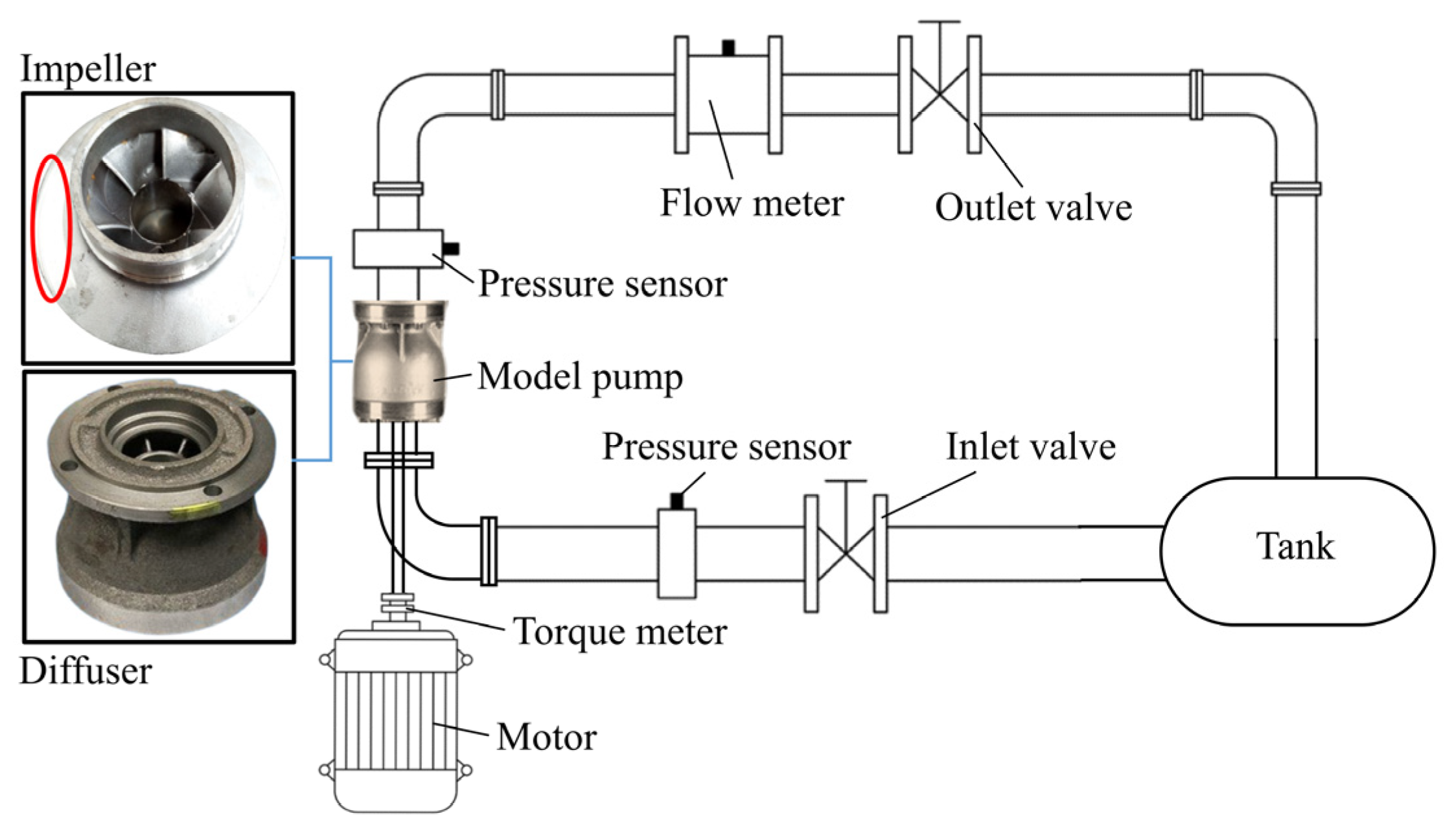
To further ensure the accuracy of the numerical results, a performance test of the model pump is carried out, as shown in Figure 5. The impeller and diffuser used for the test are manufactured using a stainless steel precision casting process. Since the impeller has a large outer diameter, it underwent dynamic balancing experiments to avoid an unstable system operation caused by the offset of its gravity. The red oval area on the impeller in Figure 5 represents the result of the dynamic balancing experiment. The real-time flow of the pump is monitored using an electromagnetic flow meter, while the instantaneous pressure at the pump inlet/outlet is collected using pressure sensors. Simultaneously, the torque and speed of the pump were monitored using a torque meter. All monitoring data are transmitted to the computer in real-time, and the head and efficiency of the mixed flow pump are calculated.
The pressure sensor in the experimental system has a range of 0–300 kPa with a permissible error of Dp = ±0.5%. The electromagnetic flow meter model is DN200, with a range of 0–400 m3/h and a permissible error in measurement of DQ = ±0.5%. The torque meter can measure a maximum torque value of 300 N·m, with a permissible error of DM = ±0.2% in its torque measurement and a permissible error of DN = ±0.1% in its rotational speed measurement.
Thus, the measurement error of the head is
The measurement error of the flow rate is
The measurement error of the shaft power is
The total systematic error of the test bench can then be obtained as
It can be assumed that the experimental results are accurate and reliable as the error of the test system is less than 1%.
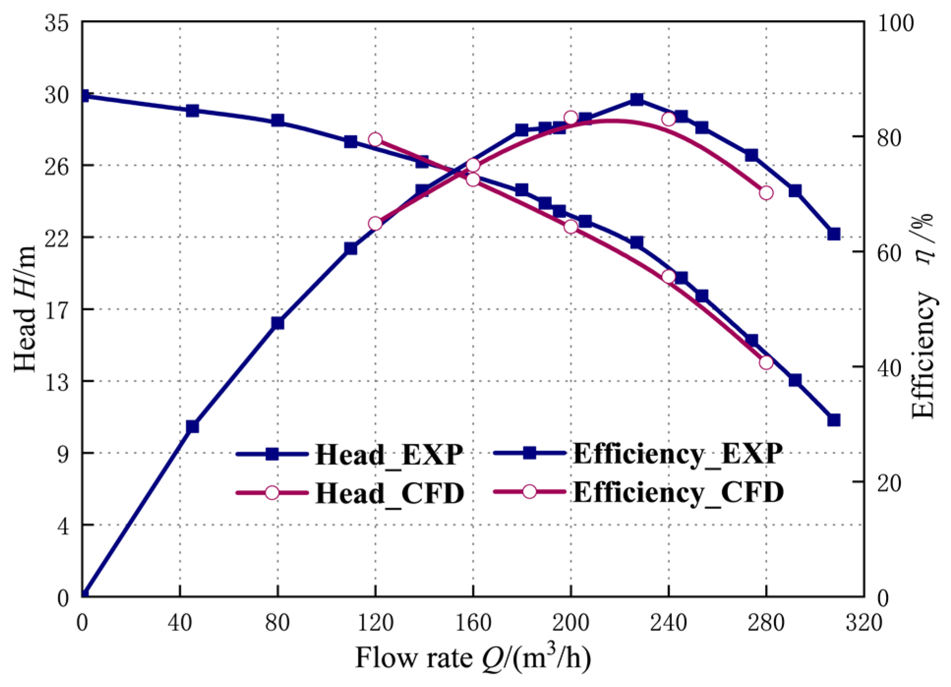
The comparison between the test results and the numerical results of the mixed-flow pump performance is shown in Figure 6. At the rated flow condition, the numerical predicted head and the test head have an error ≤1.5% and the numerical efficiency and the test efficiency have an error ≤2%. This indicates that the performance of the mixed flow pump at rated flow condition can be more accurately predicted by the numerical method used in this paper. At small flow rates (0.6 Qdes), the numerical predictions of head and efficiency are slightly higher than the experimental results due to an increase in pump head and internal pressure, leading to an increase in volume losses during the test. However, the change could not be detected by the numerical simulation, resulting in higher numerical results than experimental results. At high flow conditions (1.4 Qdes), the numerical predictions of head and efficiency are significantly lower than the test results due to the strong fluctuation state of the pump head when the flow rate deviates from the rated flow condition. The instantaneous data obtained from the test are located just near the extreme value of the fluctuation state, indicating that the mixed-flow pump exhibits more obvious transient characteristics at this time. In summary, both the numerical results and the experimental results have errors within 4% under full flow conditions (0.6 Qdes~1.4 Qdes), and both keep the same trend with the change of flow rate. Therefore, the numerical methods adopted in this paper have a relatively high accuracy.
4.2. Flow Field Pattern within Impeller and Chamber
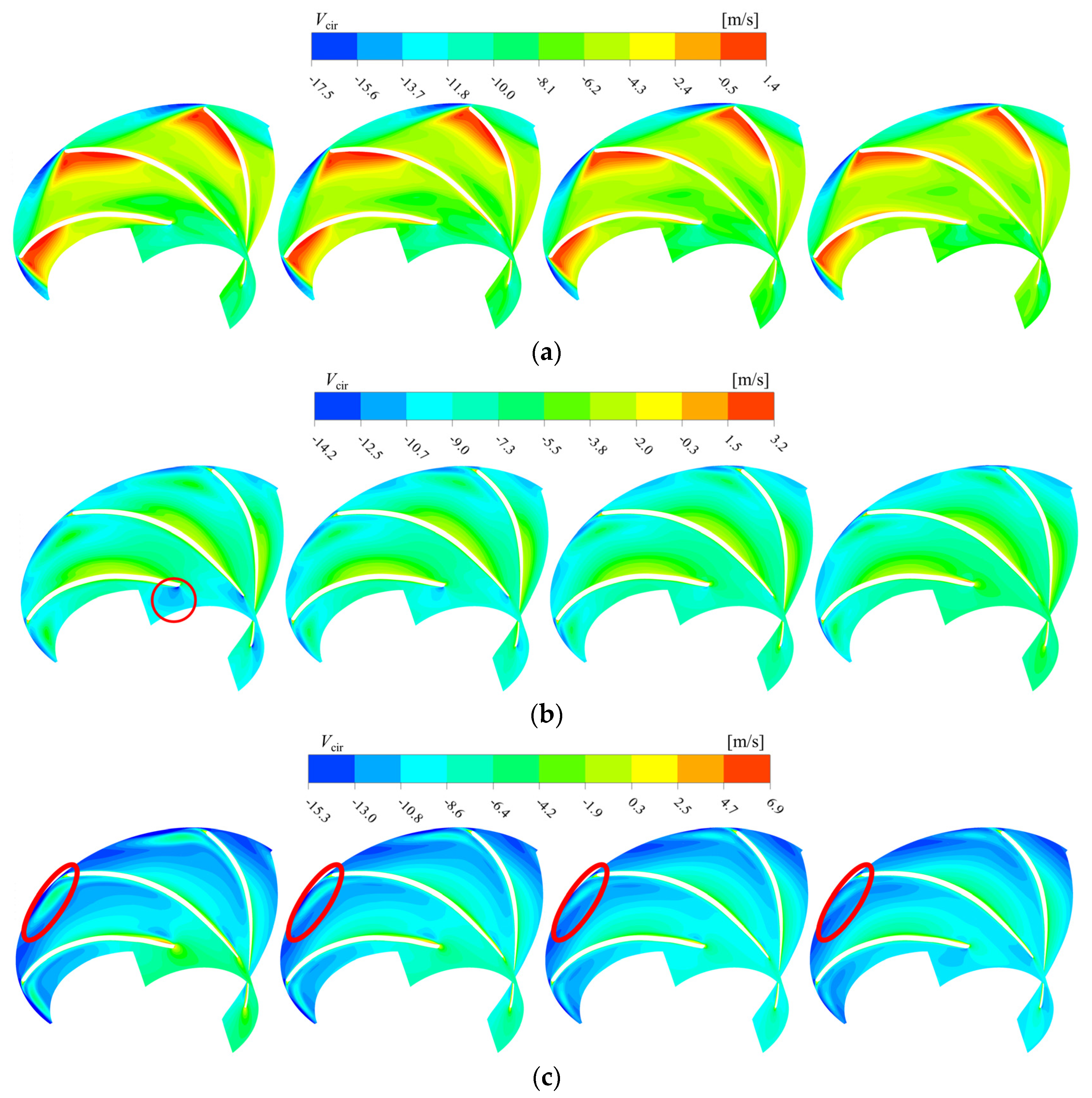
The circumferential velocity at the mid-span of the impeller with different inlet pre-swirl strength is shown in Figure 7. At small flow conditions, the circumferential velocity near the working surface at the blade inlet is slightly larger than that near the back surface. A significant crowding effect on the incoming flow is observed at the inlet edges of the blades. The circumferential velocity at the working surface and the back surface near the blade inlet is significantly reduced with the increase of the inlet pre-swirl angle. This indicates that the match of the blade inlet resting angle and the media flow angle is enhanced, and the intensity of the crowding effect is reduced under small flow rates. The area with high circumferential velocity within the impeller passage under small flow conditions is mainly concentrated at the area near the back surface of the middle and trailing sections. The area with high circumferential velocity is significantly reduced with the increase of the inlet pre-swirl angle. This indicates that the intensity of the secondary flow within the flow path is significantly reduced, which could have a good positive effect on the suppression of the “wake” and “jet” intensity in the pump cavity.
Significant enhancement of the mismatch between the blade inlet resting angle and the media incoming flow angle is observed under rated flow conditions. At an inlet pre-swirl angle of 0°, a red circle inside the pump cavity shows an obvious low-speed zone at the back surface of the blade inlet, indicating that the media tends to enter the flow channel near the working surface side. This is caused by the adoption of positive stroke angles in pump design to enhance its hydraulic performance, which results in uneven distribution of media velocity and pressure in the flow channel and eventually leads to stronger dynamic–static interference. As the inlet pre-swirl angle increases, the low-speed zone range in the red circle area continues to decrease. The highest match between the blade inlet resting angle and the media flow angle is observed at an inlet pre-swirl angle of 30°, which also leads to more uniform velocity distribution in the impeller passage.
With further increase of the flow rate, the impulse angle changes to negative at high flow conditions. A clear low-speed zone appears at the working surface near the blade inlet side, and there is a tendency for this low-speed zone to connect with the low-speed zone in the latter half of the runner. With the increase of inlet pre-swirl angle, the low-speed zone near the inlet gradually shifts from the working surface to the back surface. The circumferential velocity in the first half of the flow channel was significantly reduced, and the circumferential velocity distribution in the second half of the flow channel did not show significant changes. It is worth mentioning that the influence range of the high circumferential velocity jet (within the red elliptical region) developing from the back tail of the blade decreases continuously with increasing inlet pre-swirl angle. This is a useful aid in suppressing the intensity of the jet propagating from the impeller into the chamber, which in turn weakens the intensity of dynamic–static interference.
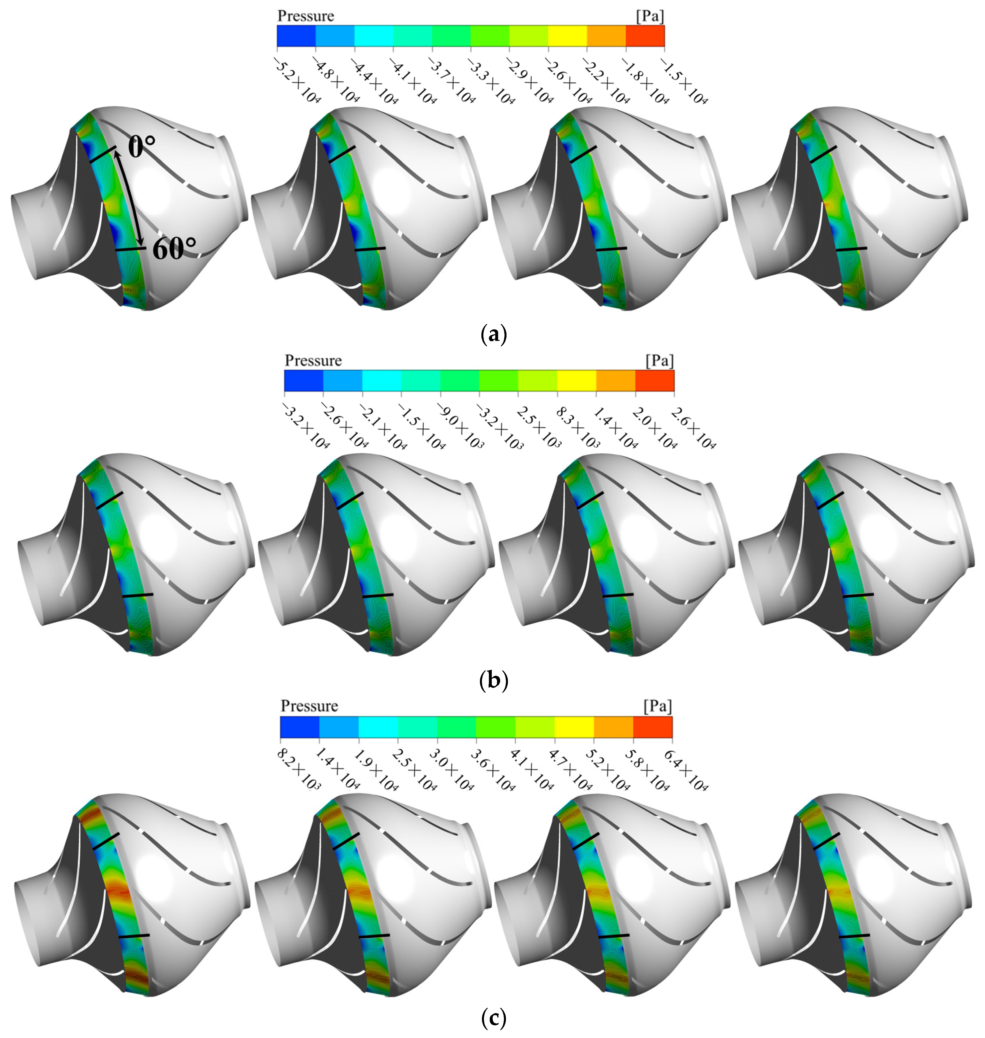
The pressure distribution on the min-span cross section of the chamber at different inlet pre-swirl strengths is shown in Figure 8. For the purpose of analysis, two short black lines differing by 60° in the circumferential direction are positioned and marked in the figure. Since the flow field in the chamber is periodic in the circumferential direction, the area between the two short black lines completely contains the “trailing-jet” phenomenon. Under small flow conditions, the low-pressure region in the pump chamber decreases as the inlet pre-swirl angle increases. This indicates that the intensity of the jet is decreasing, which is consistent with the pattern exhibited in the impeller runners in Figure 7. Therefore, the intensity of dynamic–static interference in the chamber decreases with the increase of the inlet pre-swirl angle. As the flow rate increases, the transient characteristics of the mixed flow pump are significantly weaker at rated flow conditions in comparison to small flow conditions. There is a significant reduction in both wake and jet intensity in the pump cavity. At this point, the pressure distribution is not significantly affected by the increase of the inlet pre-swirl angle. As the flow rate is further increased, the pump’s operating condition deviates from the design condition again, resulting in an elevated inhomogeneity of its flow field. This is demonstrated by a significant increase in the range of red high-pressure areas shown in the figure, indicating an increase in the strength of the trails in the pump chamber. Furthermore, as the inlet pre-swirl angle increases, the pressure in the high-pressure core region is reduced and the diffusion effect of the trails is significantly diminished.
4.3. Comparative Analysis of Pressure Pulsation
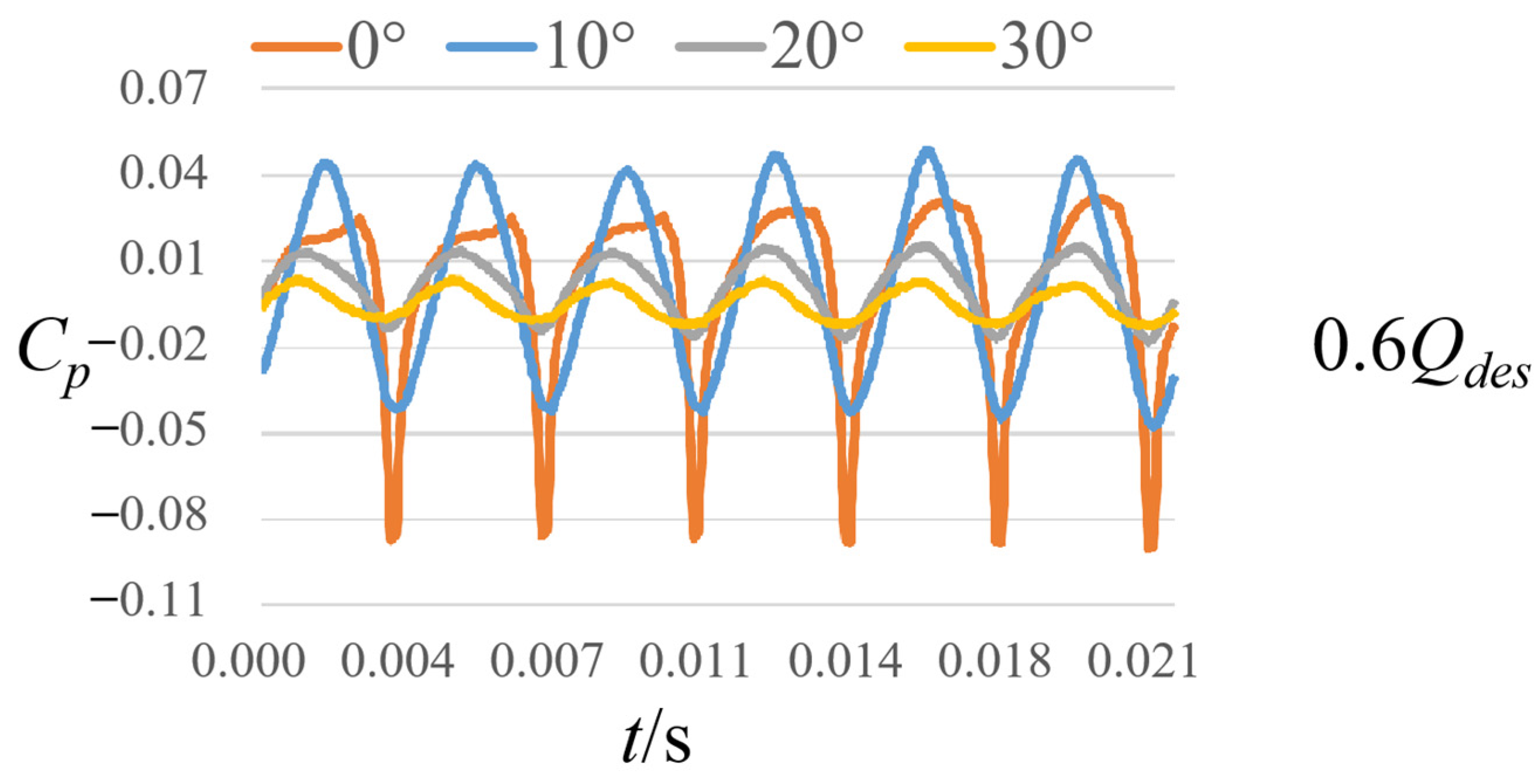
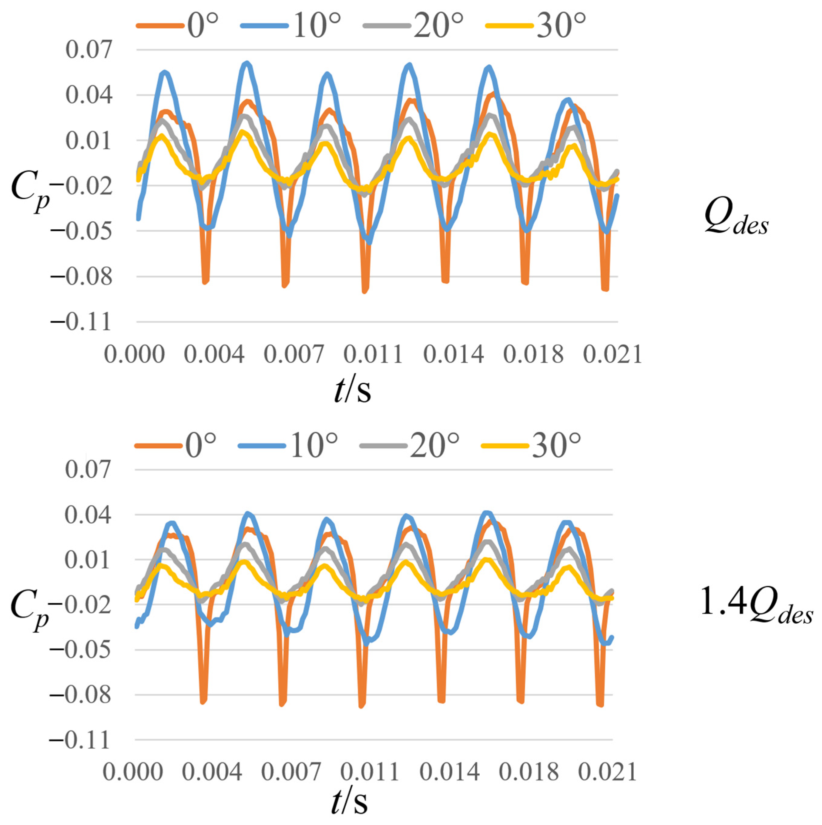
Through the flow field analysis of Figure 7 and Figure 8, it can be seen that the inlet pre-rotation can somewhat weaken the displacement effect of the blade inlet, reducing the secondary flow intensity within the impeller. This, in turn, suppresses the wake and jet in the pump cavity and finally reduces the dynamic–static interference intensity. To verify the results of the above analysis, Figure 9 compares the intensity of pressure pulsation at monitoring point P with different inlet pre-swirl angles. The pressure data were processed in an unmeasured manner to obtain the pressure pulsation coefficient Cp, which was calculated as follows.
where p is the transient pressure, Pa; is the average pressure during the impeller rotation circle, Pa; u2 is the impeller outlet circumferential velocity, m/s; ρ is the density of liquid medium, kg/m3.
At monitoring point P, the pressure pulsation has a clear periodicity. During one cycle of impeller rotation, the pressure pulsation appears for six periods, which is related to the number of impeller blades. As the inlet pre-rotation angle increases, the phase of the pressure pulsation curve does not change, but the amplitude of the pulsation decreases significantly. It is easy to see that the line shape of the pressure pulsation curve does not change significantly for each flow condition. This is due to the fact that the P point is located in the dynamic–static interference region in the pump chamber, which is the source of pressure pulsation within the pump flow path. Selecting the pressure pulsation at this location for analysis eliminates changes in the properties of the pressure pulsation due to propagation, interference, and other factors. In summary, the increase of inlet pre-swirl can reduce the intensity of pressure pulsation within the pump, which is consistent with the results of the above flow field analysis. Meanwhile, the inlet pre-swirl does not change the periodicity of the pressure pulsation and its variation pattern with time.
5. Conclusions
The effect mechanism of inlet pre-swirl on pressure pulsation within a mixed-flow centrifugal pump is investigated in this work. Numerical calculations are performed for scenarios with different inlet pre-swirl angles, and the internal flow fields of each scenario are carefully compared and analyzed. The pressure pulsation at the monitoring points in each scheme is compared, and the main conclusions can be extracted as follows:
(1) The medium is subjected to crowding effect on the inlet side of the impeller blade; the blade inlet resting angle is not exactly matched with the incoming flow angle, resulting in non-uniform distribution of velocity and pressure within the flow channel. The effect of positive impulse angle can be weakened to some extent by the inlet pre-swirl, which leads to a more uniform distribution of the flow field in the impeller and a reduction in the intensity of the secondary flow in the flow channel.
(2) The increase in the inlet pre-swirl angle improves the match between the blade inlet resting angle and the incoming flow angle of the medium. This effectively reduces the intensity of the secondary flow in the impeller flow channel, thus weakening the strength of the “jet” structure propagating from the impeller to the chamber. In particular, an inlet pre-swirl angle of 30° gives the best match between the blade inlet resting angle and incoming flow angle, effectively suppressing the unstable flow structure in the impeller.
(3) As the inlet pre-rotation angle increases, the intensity of the wake and jet in the pump cavity is significantly reduced, significantly weakening the dynamic–static interference phenomenon. Inlet pre-rotation will not change the periodicity and phase of the pressure pulsation but can significantly reduce the amplitude of its pulsation.
Author Contributions
Conceptualization, X.M.; software, M.B.; validation, T.D.; formal analysis, L.T.; investigation, L.T.; resources, J.W.; data curation, M.B.; writing—original draft preparation, Y.Y.; writing—review and editing, X.M.; supervision, X.M. All authors have read and agreed to the published version of the manuscript.
Funding
This work was supported by the Ningxia Hui Autonomous Region Key R&D Projects (No. 2021BEG02012), the Natural Science Foundation of Ningxia Province of China (No. 2021AAC03188) and the National Natural Science Foundation of China (No. 52109085).
Data Availability Statement
Not applicable.
Conflicts of Interest
The authors declare no conflict of interest.
Nomenclature
| Symbols | |
| Q | flow rate, m3/h |
| n | rotational speed, r/min |
| H | head, m |
| ns | specific speed |
| Z1 | number of impeller blade |
| Z2 | number of diffuser vane |
| Din | diameter of inlet, mm |
| DShr | diameter of shroud, mm |
| DHub | diameter of hub, mm |
| DOut | diameter of outlet, mm |
| Dout1 | diameter of outlet outer, mm |
| DOut2 | diameter of outlet inner, mm |
| bOut | width of outlet, mm |
| k | turbulent kinetic energy, m2/s2 |
| ω | turbulent eddy frequency, s−1 |
| ε | turbulent dissipation rate, m2/s3 |
| vt | turbulent viscosity, m2/s |
| F1, F2 | blending function |
| S | vorticity, s−1 |
| y | near-wall distance, m |
| y+ | dimensionless wall distance |
| DH | error in head measurement |
| DT | error in shaft power measurement |
| DQ | error in flow measurement |
| DS | total systematic error |
| p | transient pressure, Pa |
| average pressure during impeller rotation circle, Pa | |
| u2 | impeller outlet circumferential velocity, m/s |
| ρ | density of liquid medium, kg/m3 |
| Abbreviations | |
| SST | shear stress transport |
| GGI | general grid interface |
References
- Muggli, F.A.; Holbein, P.; Dupont, P. CFD calculation of a mixed flow pump characteristic from shutoff to maximum flow. J. Fluids Eng. 2002, 124, 798–802. [Google Scholar]
- Kim, J.H.; Ahn, H.J.; Kim, K.Y. High-efficiency design of a mixed-flow centrifugal pump. Sci. China Ser. E Technol. Sci. 2010, 53, 24–27. [Google Scholar]
- Li, W.; Li, E.; Ji, L.; Zhou, L.; Shi, W.; Zhu, Y. Mechanism and propagation characteristics of rotating stall in a mixed-flow centrifugal pump. Renew. Energy 2020, 153, 74–92. [Google Scholar]
- Miyabe, M.; Maeda, H.; Umeki, I.; Jittani, Y. Unstable head-flow characteristic generation mechanism of a low specific speed mixed flow pump. J. Therm. Sci. 2006, 15, 115–120. [Google Scholar]
- Wang, K.; Liu, H.; Zhou, X.; Wang, W. Experimental research on pressure fluctuation and vibration in a mixed flow pump. J. Mech. Sci. Technol. 2016, 30, 179–184. [Google Scholar]
- Zhang, M.; Tsukamoto, H. Unsteady hydrodynamic forces due to rotor-stator interaction on a diffuser pump with identical number of vanes on the impeller and diffuser. ASME J. Fluids Eng. 2005, 127, 743–751. [Google Scholar]
- Predin, A.; Biluš, I. Prerotation flow measurement. Flow Meas. Instrum. 2003, 14, 243–247. [Google Scholar]
- Figurella, N.; Dehner, R.; Selamet, A.; Miazgowicz, K.; Karim, A.; Host, R. Effect of aerodynamically induced pre-swirl on centrifugal compressor acoustics and performance. SAE Int. J. Passeng. Cars-Mech. Syst 2015, 8, 995–1002. [Google Scholar]
- Liu, Z.; Yang, H.; He, H.; Yu, P.; Wei, Y.; Zhang, W. Flow instability in a volute-free centrifugal fan subjected to non-axisymmetric pre-swirl flow from upstream bended inflow tube. Proc. Inst. Mech. Eng. Part A J. Power Energy 2022, 236, 689–713. [Google Scholar]
- Tan, L.; Cao, S.; Gui, S. Hydraulic design and pre-whirl regulation law of inlet guide vane for centrifugal pump. Sci. China Technol. Sci. 2010, 53, 2142–2151. [Google Scholar]
- Tan, L.; Zhu, B.; Cao, S.; Wang, Y.; Wang, B. Influence of prewhirl regulation by inlet guide vanes on cavitation performance of a centrifugal pump. Energies 2014, 7, 1050–1065. [Google Scholar] [CrossRef]
- Fukutomi, J.; Nakamura, R. Performance and internal flow of cross-flow fan with inlet guide vane. JSME Int. J. Ser. B Fluids Therm. Eng. 2005, 48, 763–769. [Google Scholar] [CrossRef] [Green Version]
- Coppinger, M.; Swain, E. Performance prediction of an industrial centrifugal compressor inlet guide vane system. Proc. Inst. Mech. Eng. Part A J. Power Energy 2000, 214, 153–164. [Google Scholar] [CrossRef]
- Ceyrowsky, T.; Hildebrandt, A.; Schwarze, R. Numerical investigation of the circumferential pressure distortion induced by a centrifugal compressor’s external volute. In Turbo Expo: Power for Land, Sea, and Air; American Society of Mechanical Engineers: New York, NY, USA, 2018; Volume 51005, p. V02BT44A015. [Google Scholar]
- Carretta, M.; Cravero, C.; Marsano, D. Numerical prediction of centrifugal compressor stability limit. In Turbo Expo: Power for Land, Sea, and Air; American Society of Mechanical Engineers: New York, NY, USA, 2017; Volume 50800, p. V02CT44A007. [Google Scholar]
- González, J.; Santolaria, C. Unsteady flow structure and global variables in a centrifugal pump. J. Fluids Eng. 2006, 2006128, 937. [Google Scholar] [CrossRef]
- Yang, J.; Yuan, S.; Yuan, J.; Si, Q.; Pei, J. Numerical and experimental study on flow-induced noise at blade-passing frequency in centrifugal pumps. Chin. J. Mech. Eng. 2014, 27, 606–614. [Google Scholar] [CrossRef]
- Li, H.; Huang, Q.; Pan, G.; Dong, X.; Li, F. An investigation on the flow and vortical structure of a pre-swirl stator pump-jet propulsor in drift. Ocean Eng. 2022, 250, 111061. [Google Scholar] [CrossRef]
- Dong, R.; Chu, S.; Katz, J. Effect of modification to tongue and impeller geometry on unsteady flow, pressure fluctuations, and noise in a centrifugal pump. J. Turbomach. 1997, 119, 506–515. [Google Scholar] [CrossRef] [Green Version]
- Yuan, Z.; Jun, L.; Daqing, Z. Pressure pulsation of model test in large-size axial-flow pump. J. Drain. Irrig. Mach. Eng. 2010, 28, 51–55. [Google Scholar]
- Yang, Y.; Zhou, L.; Shi, W.; He, Z.; Han, Y.; Xiao, Y. Interstage difference of pressure pulsation in a three-stage electrical submersible pump. J. Pet. Sci. Eng. 2021, 196, 107653. [Google Scholar] [CrossRef]
- Yang, Y.; Zhou, L.; Han, Y.; Lv, W.; Shi, W.; Pan, B. Pressure pulsation investigation in an electrical submersible pump based on Morlet continuous wavelet transform. Proc. Inst. Mech. Eng. Part C J. Mech. Eng. Sci. 2021, 235, 6069–6079. [Google Scholar] [CrossRef]
- Karassik, I.J.; Messina, J.P.; Cooper, P.; Heald, C.C. Pump Handbook; McGraw-Hill Education: New York, NY, USA, 2008. [Google Scholar]
- Ji, L.; Li, W.; Shi, W.; Tian, F.; Agarwal, R. Diagnosis of internal energy characteristics of mixed-flow pump within stall region based on entropy production analysis model. Int. Commun. Heat Mass Transf. 2020, 117, 104784. [Google Scholar] [CrossRef]
Figure 1.
Main dimensions of mixed-flow pump.

Figure 2.
Computational domain model and boundary conditions.

Figure 3.
Grid details of main hydraulic components. (a) Impeller; (b) Diffuser.

Figure 4.
Monitoring points arrangement.

Figure 5.
Test bench system.

Figure 6.
Comparison of numerical predictions of pump performance with test results.

Figure 7.
Circumferential velocity at min-span of impeller with different inlet pre-swirl angle. Tips: The inlet pre-swirl angles from left to right clouds are 0, 10, 20, and 30. (a) 0.6Qdes; (b) Qdes; (c) 1.4Qdes.
Figure 7.
Circumferential velocity at min-span of impeller with different inlet pre-swirl angle. Tips: The inlet pre-swirl angles from left to right clouds are 0, 10, 20, and 30. (a) 0.6Qdes; (b) Qdes; (c) 1.4Qdes.

Figure 8.
Pressure distribution on min-span of the chamber with different inlet pre-swirl angle. Tips: The inlet pre-swirl angles from left to right clouds are 0, 10, 20, and 30. (a) 0.6Qdes; (b) Qdes; (c) 1.4Qdes.
Figure 8.
Pressure distribution on min-span of the chamber with different inlet pre-swirl angle. Tips: The inlet pre-swirl angles from left to right clouds are 0, 10, 20, and 30. (a) 0.6Qdes; (b) Qdes; (c) 1.4Qdes.

Figure 9.
Intensity of pressure pulsation at point P with different inlet pre-swirl angle.


Table 1.
Specific features of the impeller and diffuser.
| Impeller | Diffuser | ||
|---|---|---|---|
| Number of blades Z1 | 6 | Number of vanes Z2 | 7 |
| Diameter of shroud DShr (mm) | 120 | Diameter of inlet Din (mm) | 187.2 |
| Diameter of hub DHub (mm) | 45.6 | Diameter of outlet outer Dout1 (mm) | 120 |
| Diameter of outlet DOut (mm) | 162 | Diameter of outlet inner DOut2 (mm) | 66 |
| Width of outlet bOut (mm) | 36 | ||
Table 2.
Grid independence analysis.
| Maximum Grid Size (mm) | 2.4 | 2.2 | 2 | 1.8 | 1.6 |
| Number of Grids (×106) | 2.9 | 4.8 | 5.7 | 7.0 | 9.1 |
| Predicting Head (m) | 22.68 | 22.55 | 22.39 | 22.36 | 22.37 |
| Predicting Efficiency (%) | 84.52 | 83.94 | 83.50 | 83.27 | 83.24 |
Disclaimer/Publisher’s Note: The statements, opinions and data contained in all publications are solely those of the individual author(s) and contributor(s) and not of MDPI and/or the editor(s). MDPI and/or the editor(s) disclaim responsibility for any injury to people or property resulting from any ideas, methods, instructions or products referred to in the content. |
© 2023 by the authors. Licensee MDPI, Basel, Switzerland. This article is an open access article distributed under the terms and conditions of the Creative Commons Attribution (CC BY) license (https://creativecommons.org/licenses/by/4.0/).
Share and Cite
MDPI and ACS Style
Ma, X.; Bian, M.; Yang, Y.; Dai, T.; Tang, L.; Wang, J. Study on the Effect Mechanism of Inlet Pre-Swirl on Pressure Pulsation within a Mixed-Flow Centrifugal Pump. Water 2023, 15, 1223. https://doi.org/10.3390/w15061223
AMA Style
Ma X, Bian M, Yang Y, Dai T, Tang L, Wang J. Study on the Effect Mechanism of Inlet Pre-Swirl on Pressure Pulsation within a Mixed-Flow Centrifugal Pump. Water. 2023; 15(6):1223. https://doi.org/10.3390/w15061223
Chicago/Turabian StyleMa, Xiaogang, Mengying Bian, Yang Yang, Tingting Dai, Lei Tang, and Jun Wang. 2023. "Study on the Effect Mechanism of Inlet Pre-Swirl on Pressure Pulsation within a Mixed-Flow Centrifugal Pump" Water 15, no. 6: 1223. https://doi.org/10.3390/w15061223
Note that from the first issue of 2016, this journal uses article numbers instead of page numbers. See further details here.