
Examining Current and Future Applications of Electrocoagulation in Wastewater Treatment


1
UCD Dooge Centre for Water Resources Research, School of Civil Engineering, University College Dublin, Belfield, D04 V1W8 Dublin, Ireland
2
State Key Laboratory of Eco-Hydraulics in Northwest Arid Region, Xi’an University of Technology, Xi’an 710048, China
*
Author to whom correspondence should be addressed.
Water 2023, 15(8), 1455; https://doi.org/10.3390/w15081455
Submission received: 8 March 2023
/
Revised: 2 April 2023
/
Accepted: 5 April 2023
/
Published: 7 April 2023
(This article belongs to the Section Wastewater Treatment and Reuse)
Abstract
:Electrocoagulation (EC) has gained increasing attention as an effective and environmentally friendly technique for purifying water and wastewater. This review provides a comprehensive analysis of the recent literature on EC and identifies new trends and potentials for further research. Initially, the nature of EC and its operating parameters are discussed, while the research trends are analyzed using the Scopus database and VOSviewer software. From 1977 to 2022, 2691 research articles and review papers on EC for water/wastewater treatment were published, with the number of publications increasing from 2 in 1977 to 293 in 2022. In the past five years, most studies focused on treatment performance and the mechanism of EC systems. However, recent emphasis has been placed on combining EC with other treatment processes and addressing emerging pollutants. The innovative applications of EC are highlighted, including the removal of microplastics and per/polyfluoroalkyl substances, the power supply of EC via microbial fuel cells (MFCs) and electro-wetlands (EWs), and the application of power management systems in EC. The review concludes with suggestions for further research to enhance the technology and expand its scope of applications.
1. Introduction
Water scarcity and pollution have become increasing global problems due to population growth, industrialization, and the overuse of water resources. In 2020, only 74% (5.8 billion) of the global population had access to ‘safely managed’ drinking water services [1,2]. This term refers to access to improved water sources, which are located on their premises, available when needed, and free from fecal and priority chemical contamination. However, the remaining two billion people still live without safely managed drinking water services, with 1.2 billion people lacking even a basic level of service. Approximately 80% live in rural areas, and half live in the least-developed countries. The United Nations Sustainable Development Goal targets 6.1 and 6.A aim to achieve, by 2030, universal and equitable access to safe and affordable drinking water and building support to developing countries in water- and sanitation-related activities and programs, including water harvesting, desalination, water efficiency, wastewater treatment, recycling, and reuse technologies [1].
This has prompted research into developing low-cost, easily constructed and maintained, and sustainable technologies for water treatment and recycling in rural or less-developed areas. Electrocoagulation (EC) is a water purification system that uses micro-electrical current to remove contaminants in aqueous environments. It is an alternative to chemical coagulation (CC), which involves delivering metallic coagulants to water through the electro-dissolution of electrodes. Both methods aim to remove finely dispersed particles from water/wastewater by destabilizing or neutralizing the repulsive forces that keep the particles suspended in the water. This process leads to the formation of larger particles that can settle and be more easily separated from the water.
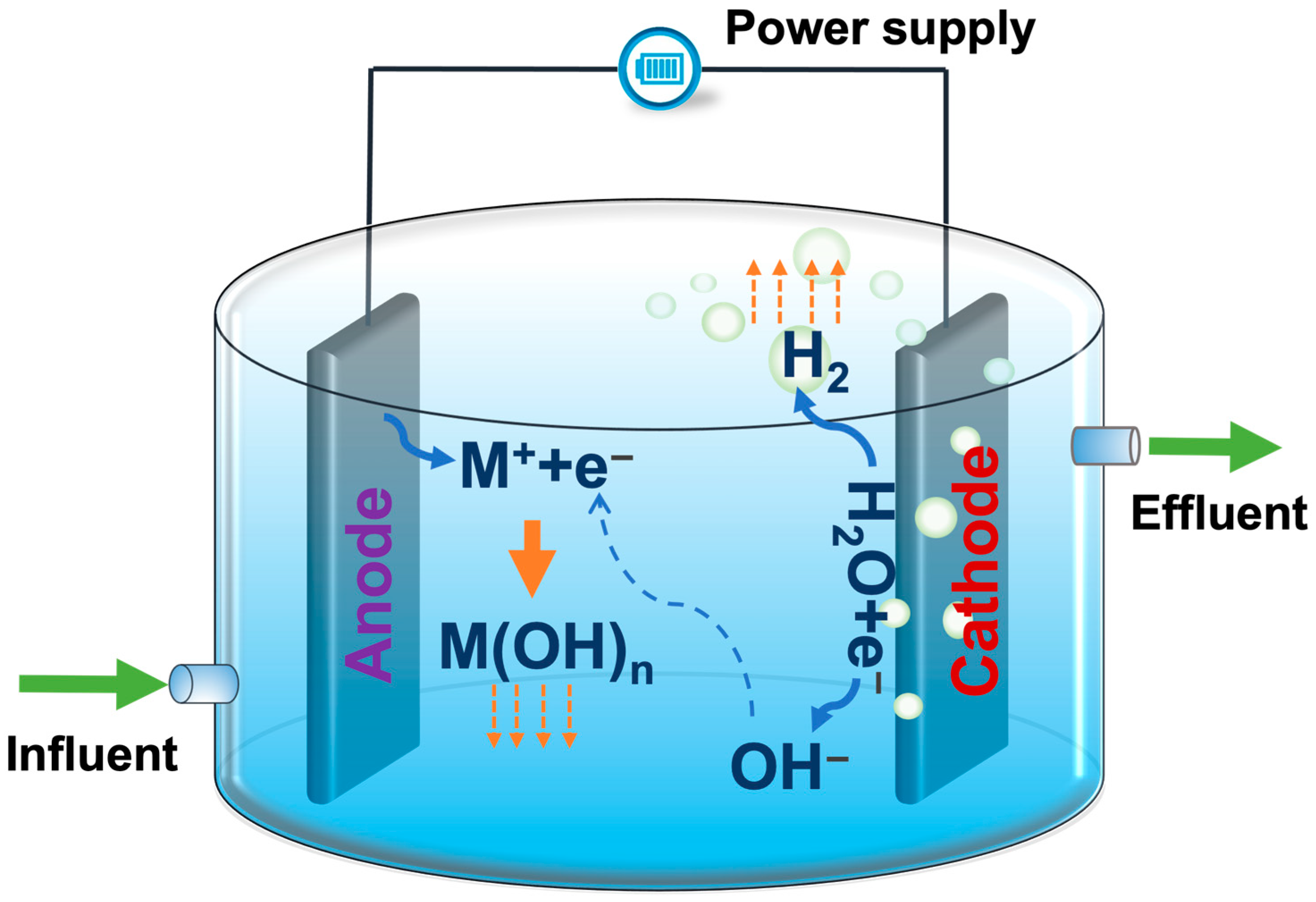
EC combines the benefits of coagulation, flotation, and electrochemistry in one system [3,4]. EC consists of an electrolytic cell with two electrodes (an anode and a cathode) immersed in a conducting solution to be treated and coupled to an external electricity power supplier (Figure 1). There are several steps in the EC process:
- (1)
- When an electric current is supplied from an external power source, the active coagulant cations (usually aluminum or iron) are released into the solution by the electrolytic oxidation of a sacrificial anode Equations (1) and (4);
- (2)
- Simultaneously, hydroxyl ions are produced due to cathode hydrolysis Equation (6);
- (3)
- The metal cations react with hydroxyls to form monomeric and polymeric species Equations (2), (3) and (5);
- (4)
- Neutralization of the surface charge of contaminants, suspended particulate matter, and emulsions is achieved due to its reaction with metal hydroxyls;
- (5)
- Agglomeration of neutralized particles and their coagulation occurs in the aqueous phase as flocs;
- (6)
- Precipitation of heavier flocs takes place by sedimentation via sweep coagulation;
- (7)
- Hydrogen bubbles are produced at the cathode by water electrolysis, resulting in the floatation of flocs at the surface of the solution via sweep coagulation Equation (6).
Anode reactions:
Cathode reactions:
The anode dissociation follows Faraday’s law Equation (7). Where, is the mass of anode dissolved (g), I is the current (A), t is the operation time (s), Mw is the molecular weight of anode (aluminum, 29.89 g/mol), F is Faraday’s constant (96,487 C/mol), and z is the number of electrons involved in the reaction.
In some cases, the actual anode dissolution does not match the theoretical anodic dissolution calculated by Faraday’s law, which indicates that other electrochemical reactions might be taking place at the anode. Several authors suggested that the evolution of oxygen at the anode might take place at alkaline pH and sufficiently high anodic potential Equation (8) [5]
In 1889, the first study to use electricity for sewage treatment was proposed in the United Kingdom [6], and this gained interest and was widely applied globally from the 1970s onwards [7]. There are a vast number of published research papers from the last two decades that sought to investigate the performance of EC for the treatment of different wastewater. Previous studies have reported that EC is effective for the removal of contaminants such as heavy metals [8,9], oil droplets [10], dyes [11], suspended solids [12], natural organic matter (NOM) [13,14], and phosphorous [15,16] in wastewaters including municipal sewage, industrial wastewater, and polluted natural water [5,17,18]. In this review paper, the characteristics of EC and operational parameters are discussed, followed by an analysis of research trends of publications utilizing the Scopus database and VOSviewer software. The paper places particular emphasis on exploring novel applications of EC in recent studies, including treating emerging pollutants, utilizing sustainable bio-current sources (such as microbial fuel cells and electro-wetlands), and implementing power management systems. Additionally, the paper identifies gaps in current research and provides recommendations for future investigations that can address these gaps and overcome operational challenges.
2. Nature of Electrocoagulation and Performance-Influencing Factors
2.1. Pros and Cons of Electrocoagulation
The EC approach to coagulation has several advantages and disadvantages over traditional physio-chemical treatment methods [4,5,18,19] (Table 1). EC has advantages over CC for wastewater treatment, including faster and more efficient organic-matter separation, pH control without chemicals, lower operating costs, less secondary pollution, and easier automation. It also produces gas bubbles to facilitate pollutant removal, larger and more stable flocs and can remove even small colloidal particles. Compared to other electrochemical/chemical processes, such as photocatalysis (PC) and electro-Fenton (EF), EC is relatively inexpensive due to its lower equipment and maintenance costs and because no additional chemicals are required [20,21]. Additionally, EC can function under a wide range of conditions, including high salt and pH levels. In contrast, PC is sensitive to environmental factors such as pH, temperature, and the presence of organic matter [22], while EF only operates under a narrow acidic pH range [17,23].
However, EC has some disadvantages, including cathode passivation, periodic replacement of sacrificial anodes, the need for post-treatment due to high metal-ion concentrations, high power-consumption costs in areas with limited access to electricity, and potential sludge buildup on electrodes during continuous operation. In addition, EC utilizes electrochemical methods exclusively to eliminate pollutants without relying on biological processes, which are not very effective for breaking down biodegradable pollutants and soluble organic substances [20]. However, other treatment methods, such as PC [20,24], EF [21], microbial electrolysis cell (MEC), and microbial fuel cell (MFC) [17], may be more effective at treating water with organic pollutants. These methods involve bio-electrochemical processes or the use of chemicals and light to support the treatment process and, therefore, may be more efficient.
2.2. Removal Mechanisms
The mechanisms of coagulation–flocculation and the series of reactions and processes in the EC and CC are similar. In Al-based EC, when the aluminum anode is dissolved into Al3+ ions, they become hydrated and form the hexaaquoaluminium ion (Al(H2O)63+); see Equations (1)–(8). This ion then undergoes a series of rapid hydrolysis reactions, leading to the formation of soluble monomeric species (Al(OH)(H2O)52+) and polymeric species (Al13O4(OH)247+), as well as solid Al(OH)3 and aluminate ions (Al(OH)4−) [7,25].
For the removal of organic matter, there are several mechanisms including: (1) complexation; (2) charge neutralization or destabilization; (3) entrapment; and (4) adsorption [19]. The predominance of each mechanism depends on the nature of the pollutant (charge, size, hydrophobicity, etc.), the type of coagulant and its dosage, as well as the pH and other factors in the water matrix. It is important to note that the overall mechanism for removing pollutants through coagulation is complex and can often involve multiple mechanisms working together to improve the removal efficiency [19].
Natural organic matter (NOM) refers to organic material which consists of a diverse mix of humic substances (such as humic and fulvic acids and phenolic compounds), hydrophilic acids, proteins, lipids, and carbohydrates. ECs have been reported to treat a variety of NOM-containing waters, including peat water [13,26], river water [27,28], lake water [14,28,29], and synthetic wastewater [30,31]. Low levels of NOM in water can prevent chemical dissolution, pitting corrosion, and chlorine generation during electrolysis, as there are low levels of salinity and chloride ions [32]. In the case of using iron electrodes, Fe(II) can be converted to Fe(OH)3(s) through ‘sweep coagulation’ by increasing pH and dissolved-oxygen concentration in oxygenated water [32]. Aluminum hydroxide is the main oxide formed during Al-based EC in natural water, and the presence of NOM can disrupt its crystalline precipitation, similar to chemical precipitation with aluminum chloride [32]. Oxygen was not released during the anodic dissolution of aluminum/iron, indicating that all electrons participated in the process [32].
Aluminum electrodes can remove phosphates in water through the direct adsorption of phosphate ions, incorporation of soluble phosphates into suspended colloids, and formation of insoluble salts with aluminum [7]. However, the system of the aluminum–orthophosphate is complex, and the removal of phosphates also depends on hydrolysis products of aluminum and the Al3+ ion rather than the formation of individual AlPO4 and Al(OH)3 species [7]. The pH of the solution affects the process, with higher pH leading to the formation of aluminum–hydroxy species that can adsorb onto positively charged aluminum hydrolysis species or act as nucleation points for the further precipitation of aluminum hydrolysis products. The highest removal efficiency occurs when the concentrations of aluminum hydroxy species and phosphates are high, and the solubility of AlPO4 is low [7].
2.3. Influencing Factors
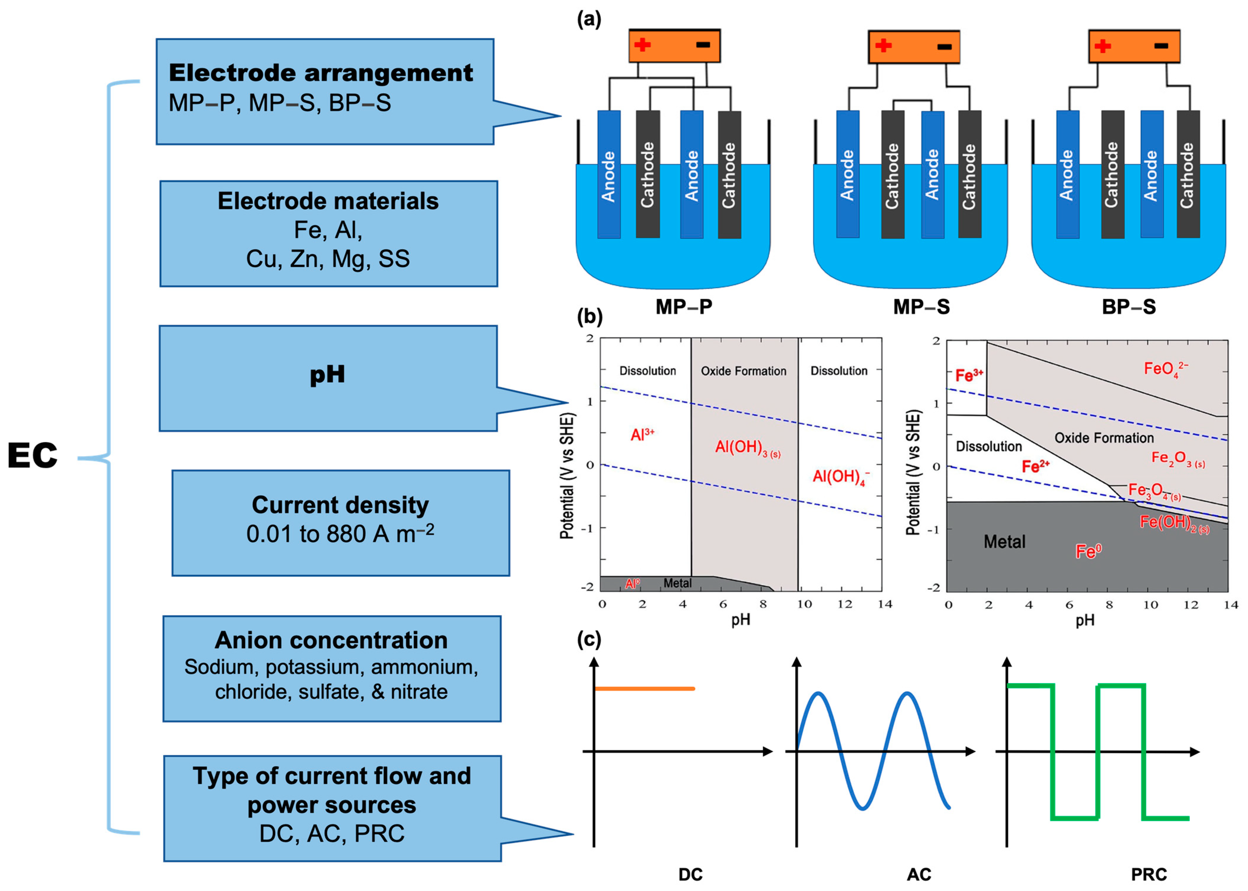
Several parameters influence electrocoagulation efficiency and its ability to remove pollutants from wastewater (Figure 2). The most important parameters include electrode materials and arrangement, pH and anion concentration, type of power sources, and current density. EC-removal efficiencies, power consumption, and operating costs under various operating conditions in previous studies are summarized in Table 2.
2.3.1. Electrode Materials and Its Arrangement
Aluminum and iron are commonly used electrode materials due to their reliability and availability [18]. Aluminum anodes dissolve as Al3+, while iron anodes dissolve as Fe2+ and Fe3+ in solutions, Equations (1) and (4). Fe2+ is highly soluble but a weak coagulant and has a lower pollutant-adsorption capacity compared to Fe3+. Iron electrodes are suitable in specific pH ranges to ensure complete oxidation of Fe2+ to Fe3+ [5]. Aluminum electrodes are more expensive but more efficient than iron electrodes [5,7]. Aluminum anodes can be paired with other materials as cathodes, such as stainless steel [33,34,35] or iron [36], for specific pollutant removal. Alternative anodic materials like copper, zinc, and magnesium can be used instead of iron or aluminum to coagulate contaminants in water. These materials dissolve to form hydroxides and help with coagulation [19,37]. However, iron and aluminum require less coagulant due to their higher charge valence [19]. It is important to note that excessive coagulant residue in treated water can be harmful to health, and EU regulations limit aluminum (200), iron (200), and magnesium (50 /L) concentrations to avoid potential health problems [38].
There are three types of electrode arrangements for electrochemical cells: monopolar–parallel (MP–P), monopolar–series (MP–S), and bipolar–series (BP–S) (Figure 2a). In MP–P, anodes are connected to each other and the power supply in a parallel configuration. In MP–S, the internal electrodes are connected to each other in a series connection. In BP–S, the inner electrodes are separated from each other and the power supply, forming a series connection [4,5]. It is important to note that a series connection requires a higher potential difference, while a parallel connection distributes the electric current among all the interconnected electrodes based on their resistance. However, a parallel-connection configuration offers significant energy savings. Thus, the MP–S connection mode uses a higher potential difference, while the MP–P connection mode has lower energy consumption. Additionally, the BP–S mode provides high pollutant removal [39,40], while the monopolar-configuration mode has a lower cost of operation [40,41].
2.3.2. pH and Anion Concentration
The electrode dissolves and forms different metal ions depending on the initial pH (pHi) of the solution. Aluminum and iron EH-pH diagrams (Figure 2b) show which compound is thermodynamically stable under given conditions. When the cell potential is between −2 V and +2 V, Al3+ is the major species present at pH < 3.5, Al(OH)3(S) for pH 4–9.5, and Al(OH)4− for pH > 10. Al(OH)3 is the main contributor to floccule and aggregate formation through complex precipitation processes [7,19]. Fe ion formation is more complicated, with the ferric ion predominant in highly acidic solutions and the ferrous ion more common in pH < 6.5. Most studies found that Fe2+ is initially formed by iron electrolysis and then oxidized to Fe3+ by dissolved oxygen when conditions are suitable (e.g., pH 5–9), after which it is then hydrolyzed to form insoluble Fe(OH)3(s) and FeOOH(s) [3,5].
In ECs, the solution around the anode is slightly acidic due to H+ formation, and the solution around the cathode is slightly alkaline due to OH− production and H2 evolution. The amphoteric character of Al(OH)3 contributes to a decrease in the solution pH when an aluminum anode is used. EC with Al anode is considered pH-neutralizing and can be used for wastewater treatment with specific pH conditions or pH-enhancement/reducing requirements [3].
The electrolyte used in electrochemical processes is important for improving solution conductivity and reducing energy consumption [42]. The type of cation and anion used can affect the electro-dissolution kinetics of sacrificial anodes and the ability of coagulants to form flocs. Sulfate and nitrate ions can inhibit electro-dissolution [3,43], while chloride (when the ratio of chloride to sulfate ions is greater than 0.1 [7]) and nitrate ions can break down passive films and improve EC processes [3]. However, high levels of chlorine can cause aluminum hydroxide to dissolve into aluminum chloride and reduce treatment effectiveness [44,45]. The supporting electrolyte can also compete with contaminants in the water, potentially affecting contaminant-removal efficiency. For example, sulfate ions can impact fluoride removal due to their ability to form precipitates with Al3+ along with fluoride ions [46]. Electrode corrosion can also be influenced by the type of electrolyte, with sulfate medium causing uniform corrosion, nitrate medium causing crevice corrosion, and chloride medium causing localized pitting corrosion [46].
2.3.3. Type of Power Sources and Current Density
EC processes rely on a power source, usually direct current (DC). Long-term use can lead to electrode passivation, reducing efficiency [47,48]. Alternating pulsed current (AC) or polarity-reversal current (PRC) can prevent passivation [3,5] and have been used in previous studies to improve EC efficiency [49,50]. AC uses a sinusoidal current, while PRC involves switching the direction of a direct current in a square-wave pattern (Figure 2c). PRC is simpler to implement and only requires a DC time relay or manual switching of the positive and negative terminals [3,47]. AC produces smoother electrodes [51,52], while PRC prevents electrode fouling and allows for more uniform metal-ion distribution [31]. It is unclear how passivation is prevented or removed during these processes, but possible mechanisms include hydrogen gas bubbles mechanically removing surface layers or dissolution of the metal beneath [48].
To reduce costs and explore more applications, onsite sustainable/renewable-energy sources with energy-storage systems used as backup power can be employed to power EC processes. These sources include solar photovoltaic [47,53], wind turbines [54,55], biomass [55,56,57], or hydroelectricity [58]. The rate of power generation by theses energy systems highly depends on the natural conditions, such as geographical latitude, the intensity of sunlight, wind speed, gravitational potential, land area, hydraulic loading, etc.
Current density is crucial in the EC process as it affects the amount of coagulant generated and the production rate, size, and density of bubbles produced. The applied current density can vary greatly, typically between 0.01 and 880 A m−2 [40]. Increasing current density produces more coagulant [13,59] and smaller bubbles that adhere better to particles [60,61], increasing removal efficiency. However, excessive current can decrease Faradaic efficiency and removal performance due to secondary reactions and electrode passivation [3,30]. Chen et al. [62] reported that with an increase in current density from 18 mA/cm2 to 52 mA/cm2, the Faradaic efficiency dropped from 116% to 80% in aluminum-based electrocoagulation. A substantial decrease in Faradaic efficiencies (from ~100% to 60%) has also been observed after a 30 min reaction at a current of 1.40 A. The theoretical dissolved rate of the anode may differ from experimental observations due to oxygen evolution and high anodic potential [7]. Excess current may also result in wasted energy and reduced current efficiency [5,63].

Table 2.
Summary of the removal efficiencies, power consumption, and operation cost of EC processes under different operating conditions.
Table 2.
Summary of the removal efficiencies, power consumption, and operation cost of EC processes under different operating conditions.
| EC Configuration | Impactor Factors | Pollutants or Wastewater | Optimum Operation Conditions | Removal Performance (%) and Power Consumption | Operation Cost | Reference |
|---|---|---|---|---|---|---|
| Batch mode; Reaction volume: 2 L; Electrode: Al (5 cm × 16.5 cm × 0.2 cm) and SS (6 cm × 16.5 cm × 0.2 cm), 5 cm apart; Stir rate: 300-rpm | CD, initial concentration, electrolysis duration, and application mode | pharmaceuticals from municipal wastewater | 48%, 44%, and 36% of DCF, CBZ, and AMX removal when the CD of 1.8 mA/cm2 | 0.1, 0.2, 0.81, and 1.57 €/m3 when CD of 0.3, 0.5, 1.15, and 1.8 mA/m2 | [33] | |
| Electrode: Fe-SS, Al-SS (70 mm × 50 mm, distance: 5 mm); Reaction Volume: 500 mL; Stir rate: 200 rpm; Voltage: 40 V; Current: 5 A. | CD, Reaction time (RT) | uranium from mine water | RT: 101.6 min, CD: 59.9 mA/cm2 | Iron system: uranium concentration: 5 μg/L, cumulative uncertainty: 25 μg/L; Power consumption: 461.7 kWh/g-U; Aluminum systerm: 96 μg/L-U; | Iron system: in the United States: 60.0 USD/g-U, South Korea: 55.4 USD/g-U and Finland: 78.5 USD/g-U; Aluminum system: 9 747 USD/g-U) | [34] |
| Batch mode; Reaction volume: 500 mL, Electrode: AL-SS and Fe-SS (70 mm × 50 mm, 5 mm apart); Stir rate: 200 rpm. | Electrode type, CD and RT | uranium from mine water | CD: 70 mA/cm2, RT: 120 min | 99.7% and 97.7% of uranium removal in Fe-SS and AL-SS system | [35] | |
| Batch mode; Reaction volume: 0.35 L; Electrode: titanium, Al, Fe (4.4 cm × 4.7 cm, effective area of 62 cm2, MP-P); Stir rate: 300 rpm | Initial pH, CD, initial phosphorus concentration, and reaction | phosphorus from domestic wastewater | pHi: 4, CD: 20 A/m2, RT: 80 min | 99.99% of removal; Power consumption: 3.422 kWh/m3 | [36] | |
| Batch mode (180 min); Reaction volume: 1000 mL; Electrode: Zn-SS (effective initial area of 33.5 cm2, connect in parallel, distance: 5–20 mm) | pH, CD, distance between electrodes, nature of electrolyte, and kind of cathode | filtered real olive mill | Initial pH: 3.2, CD: 250 A/m2, distance between electrodes: 1.0 cm and NaCl: 1.5g/L | Removal of total phenolic (TPh) and COD: 84.2% and 40.3% with NaCl, 72.3% and 20.9% without NaCl addition; Power consumption: 40 kW h/m3 (simulated WW) and 34 kW h/m3 (real WW) | [37] | |
| Reaction volume: 3 L; Electrode: Four AL (0.15 m × 0.1 m × 0.002 m, distance 0.5 cm, BP/MP connection, effective surface area 4 × 10⁻³ m2). | Initial concentrations of fluoride, electrode connections | fluoride from drinking water | RT: 30 min, CD: 625 A/m2, using BP connection | Fluoride (1 mg/L) | 0.38 US$/m3 (MP) and 0.62 US$/m3 (BP) for the initial fluoride concentration of 10 mg/L1 | [39] |
| Reaction volume: 1L; Electrode: Al or Fe (60 mm × 60 mm × 3 mm, effective area: 96 cm2, distance: 0.8 cm). | MP-P, MP-S, BP-P | textile wastewater | MP-P mode | Turbidity removal of 88.6% and 84.1%, Color removal 90.9% and 80.0%, COD removal of 69.3% and 64.1% of Al and Fe-based EC | Al-based EC: 6.439 €/m3, Fe based EC: 4.732 €/m3 | [41] |
| EC followed by advanced oxidation by photoelectro-Fenton (PEF) process with in-situ H2O2 electrogeneration and UVA light irradiation; EC electrode: Fe or Al anode (3.0 cm × 1.5 cm × 0.25 cm), SS cathode, distance: 1.0 cm. | Anode material, supporting electrolyte, pH, and current | organic pollutants | 0.05 M NaCl, pH: 6.3, CD: 200 mA, RT: 15 min | [43] | ||
| Batch mode; Reaction volume: 2 L; Anode: 10 mesh horizontal Al, Cathode: H2 evolving Al plate (14 cm × 20 cm), distance: 0.5 cm | Initial NO3− concentration, initial pH, applied CD, and NaCl concentration | nitrates | Complete removal after 100 min, 80% removal in 60 min; Power consumption: 3.9 to 96.17 kWh/kg nitrates | [44] | ||
| Anode: Al-Mg (4.0 cm × 6.0 cm), cathode: SS (surface area of 35.1 cm2, Constant CD of 11.0 mA/cm2,300 cm3 of solution | Initial concentration of phosphate | phosphates | Maximum 100% removal in AL-Mg system, 97 ± 2% removal in Al-Al; Power consumption: 3.15 to 0.15 kWh/m3 | [45] | ||
| Batch mode; Reaction volume: 1 L; Electrode: seven Al electrodes (active area: 72 cm2 of each, distance 1 cm, BP connection); Stir rate: 400 rpm | SO42−, Cl−, NO3− | fluoride | Defluoridation = 100% w/o other ions. With other ions, bulk reaction happens, residual fluoride controlled by Al (III) amount. | [46] | ||
| Reactor size: 3 cm × 12 cm. Reaction volume: 40 mL; Electrode: Al plates (thickness of 2 mm, distance of 3 mm, effective surface area of 14 cm2 of each) | DC/AC, current densities, voltages, and operation modes, polarity changing frequency, AC current | Oil from synthetic bilge water | DC powered system: 98.8 ± 0.2%, 0.378 kWh/m3 to 0.977 kWh/m3; AC powered system: 99.2 ± 0.1%, 0.787 kWh/m3 to 0.936 kWh/m3 | [48] | ||
| Batch mode; Reaction volume: 0.9 L; Electrodes: AZ31 alloy and Al plates (effective area of 76.5 cm2 and 46.6 cm2, distance of 0.5 cm), Current intensity of 0.34 A | polarity reversal frequency | Indigo carmine and chloride ions | 69.1% of chloride ions removal and 90.4% of non-purgeable dissolved organic carbon removal with 0 and 2 min polarity changes. | [49] | ||
| Reaction volume: 400 mL; Electrodes: Al-Zn (60 mm × 40 mm × 2 mm, distance 2 cm); PREC: 9 V; reversing period of 10 s; Stir rate: 600 r/min, electrolyte concentration of NaCl: 1 g/L | Voltage, pH, stirring speed | PFAs from synthetic/natural groundwater samples | Voltage: 12.0 V, pH: 7.0, and stirring speed: 400 rpm | Removal of PFBS, PFHxS, and PFOS: 87.4%, 95.6%, and 100% in the synthetic aqueous solutions, and 59.0%, 88.2%, and 100% in the natural groundwater | [50] | |
| Reaction volume: 1.0 L; Electrode: Magnesium alloy (size of 2 dm2 and distance of 0.5 cm) | pH, initial ion concentration, CD, co-existing ions | Copper | CD: 0.025 A/dm2, pH: 7.0 | Removal of 97.8 and 97.2% with an energy consumption of 0.634 and 0.996 kWh/m3 for AC and DC | [51] | |
| Reaction volume: 1 L; Electrodes: Two L-shaped Al (surface area of 100 cm2 at 1 cm distance, and 20 pores with a diameter of 4 mm); Mixing speed of 50 rpm (≈10.47 rad/s). | pHi, process time, conductivity, initial HA concentration, pulse time, current type, electrode shape, electrode surfaces | HA | 0.57 kWh/g and 90% with DC and a simple electrode; 0.43 Wh/gand 91% with DC and a perforated electrode; 0.17 Wh/g and 85% with APC and a simple electrode; 0.18 Wh/g and 87% with APC and a perforated electrode | [31] | ||
| Reaction volume: 1 l; Electrode: 30 Fe and SS rods (50 mm × 5 mm, distance of 2 cm, MP connection) | Electrode type, current type, CD, RT. | Lead and zinc from battery-making industry wastewater | EC with AC and Fe: 96.7%, 95.2%, and 0.69 kWh/m3 of lead removal, zinc removal and power consumption; EC with AC and SS: 93.8%,93.3% and 0.98 kWh/m2; EC with DC and Fe: 97.2%, 95.5% and 1.97 kW h/m2; EC with DC and SS: 93.2%, 92.5% and 2.53 kWh/m3 respectively | [52] | ||
| Reaction volume: 1.0 L; Electrode: six Al plates (distance of 1 cm, effective area of 0.0210 m2, parallel connected) Power source: solar photovoltaic module | CD and detention time, | municipal wastewater | CD: 48 A/m2, hydraulic detention time: 16 min | 90% for COD, 94.56% for turbidity, and 49.78% for TDS; Power consumption: 2.27 kWh/m3 (20 min of RT and 40 A/m2 of CD) | [53] | |
| Reaction volume: 50 mL; Electrodes: Al-AL with a conversion circuit; Power sources: a wind energy harvesting triboelectric nanogenerator | RT | algae wastewater, dye wastewater | SPEC removes 90% of algae and 97% of organic dye with self-powered treatment for 72 h. | [54] | ||
| Reaction volume: 200 mL; Electrodes: two Al plates (effective electrode area of 25.3 cm2 and distance of 0.5 cm) Power sources: 3 MFC cells and DC | Power sources, electrode area, and distance | bilge water (EC) and municipal wastewater (MFC) | MFC stack-powered ECC removed 93% of oily organics | [56] | ||
| Batch mode (60 min of each run); Electrode: AL-SS (surface area: 60 cm2 of each, distance: 3 cm); Power sources: 6 MFCs with two 1.2 V rechargeable batteries | Synthetic and real municipal wastewater, | For synthetic wastewater treatment: 95.4%, 88.4%, and 93.8% of COD, TDS, and TSS removal; For real municipal treatment: 83.7%, 57.5%, and 85.8% of each. | 3600 $/m3 per year | [57] | ||
| Continuous mode; Reaction volume: 1 L; Stir rate: 250 rpm; Electrode: Al–Al (distance 2 cm, 6.3 cm × 7.9 cm) | HRT, drug concentration | NOM, acetaminophen | HRT at 40 min with 0.5 mg/L AP exhibited the best removal efficiency for NOM (55.9%) and AP (53.4%) removal. | US$ 0.03/m3, 0.05/m3, 0.08/m3, 0.10/m3 in 10 min, 20 min, 30 min, and 40 min HRT | [60] | |
| Reaction volume: 150 mL; Electrode: two rods (1.2 cm × 5 cm, 2.5 cm apart). | current intensity, TDS | Boron (B) from river water, oilfield produced water | 50% B removal from river water (C0 = 10 mg/L, current = 0.2 A) in 2 h; 80% B removal from produced water (C0 = 50 mg/L, current = 1.0 A) in 2 h. | [62] | ||
| EC–ultrafiltration; EC: two Fe anode (dimensions of 15 cm × 12 cm × 0.3 cm) and two graphite cathodes (15 cm × 12 cm × 1 cm), distance of electrode: 1.5 cm. | RT, CD, Initial pH | Sulfonated Humic Acid | RT: 7 min, CD: 10 mA/cm2, pH: 5. | Higher CD and operation time, lower pH, and improved SHA removal. Max removal: 89.12%. | [63] | |
| Batchwise mode: recirculation of the liquid medium at 1.0 L/min; Electrode: Fe plates (parallel connected, 10 cm × 17 cm × 0.2 cm, effective area: 170 cm2, 2.0 cm apart); CD of 318–481 A/m2 | CD, RT, and initial pH, cl− and Fe | shale gas wastewater | For turbidity removal: 318 mA/cm2, 20 min and 4.4 (pHi); for TOC removal: 481 mA/cm2, 20 min and 2.4, and for Ca2+ removal: 400 A/m2, 20 min, 3.9 (pHi) | 98.3%, 78.5%, and 56.5% for turbidity, TOC, and Ca2+ removal under the optimum conditions | 0.80 US$/m3 | [64] |
2.4. Process Economy of EC
The implementation of EC technology in water and wastewater processes not only depends on its technical feasibility but also on its cost-effectiveness. Therefore, it is essential to calculate the operational costs to determine the viability of using EC technology to evaluate not only removal efficiencies but also the economic impact of this technology. The total EC operating costs typically ( include the cost of materials (), chemicals (), electricity (), sludge generated (), maintenance (), depreciation (), and labor () [11,19,64], as Equations (9)–(12):
where is the electricity price, is the chemical price, c is the electrode material price, e is sludge dehydration and disposal cost. U is the applied voltage (V), I is the current (A), t is the time of reaction(s), V is the volume (m3) of the sample, and is the mass of NaCl addition (to increase the electrical conductivity of solutions). The mass consumption of the electrode was calculated by a function of Faraday’s law, Equation (7).
It is clear that the TOCtotal with EC is influenced by various factors, including the prices of consumables and costs related to sludge management, along with the cost of labor. The cost of electrochemical cells alone is reported to account for 30–60% of the total treatment cost in many cases [55,65]. The operating cost can be reduced by optimizing current density and treatment time and selecting appropriate electrode material and configuration [40]. However, factors such as electrode passivation and electrode thickness can increase the operating cost of materials and energy and need to be carefully evaluated [40]. These factors should be considered when calculating the cost and designing the reactor for the EC process. Additional measures such as periodically reversing electrode polarity [3,5], auto-cleaning of electrodes, and post-treatment methods can further reduce the operating cost [40].
The cost of electricity is a significant factor in the overall operating cost, particularly in areas where commercial energy networks are not available or where electricity is costly. Using renewable energy for EC could be one of the viable options to reduce costs. However, it is crucial to consider the high investment associated with some renewable energy facilities, such as solar photovoltaics [55]. This cost has been identified as a major obstacle to the widespread adoption of these technologies [66], especially for powering electrochemical treatment processes like EC.
3. Process Developments in the Past and Up to Now
3.1. Earlier Work and Updated Studies
Electrocoagulation was first proposed for sewage treatment using electrochemical processes and mixing domestic wastewater with saline water in 1887, as described in patents from Britain and France [6]. The UK carried out the first studies on the application of these patents to treat water in 1889 [6]. Two water treatment plants in the UK utilized electrochemical techniques with iron electrodes and chlorine disinfection with seawater as the source. One of these plants operated successfully for 10 years [6,67]. Thereafter, electrocoagulation was further developed and refined by researchers in Europe and the United States. In 1906, the electrocoagulation principle was patented by A. E. Dietrich for the treatment of bilge water from ships [68]. In 1909, J.T. Harries was awarded a patent in the United States for wastewater treatment by electrolysis using sacrificial aluminum and iron anodes [6]. Later, advances in chemical coagulation saw mass-produced alternatives for chemical coagulant dosing. The EC process for wastewater treatment, however, did not find widespread applications worldwide due to the relatively large capital investment and the cost of supplying electricity [69]. During the 1970s to 1980s, significant and growing interest in the use of electrocoagulation for water treatment was generated by Russian scientists [7]. Thereafter, a wide range of water and wastewater applications for electrocoagulation followed.
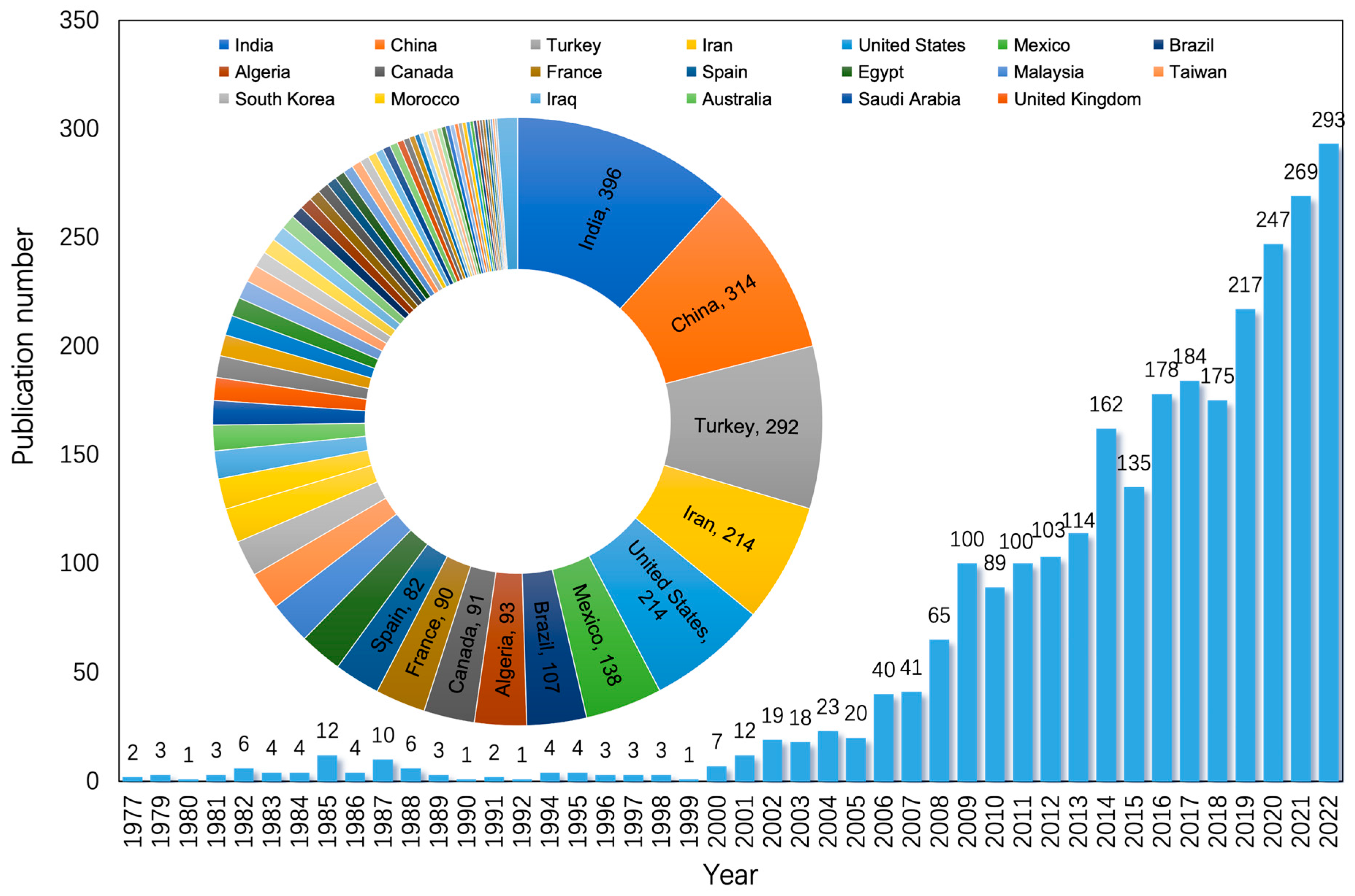
There are a total of 2691 articles published on electrocoagulation between 1977 and 2022 (Figure 3). The number of papers published annually on this topic has increased from just 2 papers in 1977 to 293 published in 2022. The first EC study published in 1977 (based on a Scopus.com search) used an EC with a continuous flow to treat fish paste manufacturing wastewater. Since 2001, the use of EC for water and wastewater treatment has gained significant attention. The majority of publications are from researchers in India (396), followed by researchers from China (314), Turkey (292), Iran (214), and the United States (214) (Figure 3). Around 7.4% (201) of these articles were review papers.
Literature reviews include Karimifard et al. [70], who discussed the use of response surface methodology (RSM) in the treatment of dye-containing wastewater through physico-chemical processes such as adsorption, advanced oxidation processes, coagulation/flocculation, and electrocoagulation. Samsami et al. [71] summarized the technologies commonly used for the removal of dyes from wastewater, including biological methods, advanced oxidation processes, electrocoagulation, adsorption, membrane technology, and photocatalytic reactors using nanomaterials. Peng and Guo [72] discussed the potential toxicity and carcinogenicity of chromium and the various methods for removing it from wastewater, including membrane filtration, chemical precipitation, ion exchange, adsorption, electrocoagulation, electrochemical reduction, electrodialysis, electrodeionization, photocatalysis, and nanotechnology. The use of EC for the treatment of different wastewaters was reviewed by Shahedi et al. and Tahreen et al. [73,74], including its effectiveness in removing various pollutants, the main challenges associated with EC, and the effects of various parameters on the effectiveness of EC. Tahreen et al. [74] also discussed emerging hybrid technologies of EC with integrated separation technologies and their limitations for enhanced wastewater treatment systems, with a focus on the hybrid EC-membrane process as a promising future technology for wastewater treatment. Moreover, the use of EC for the removal of arsenic and pharmaceutical contaminants in wastewater was reviewed by Kobya et al. and Zaied et al. [75,76], respectively, which include the mechanism and theoretical aspects of removal by EC, the effects of operational parameters on the efficiency of the process, and the reactor configurations and operating costs. Kobya et al. [75] further discussed the amount of sludge produced during EC and the characterization and disposal methods for it.
3.2. Application and Development Trends
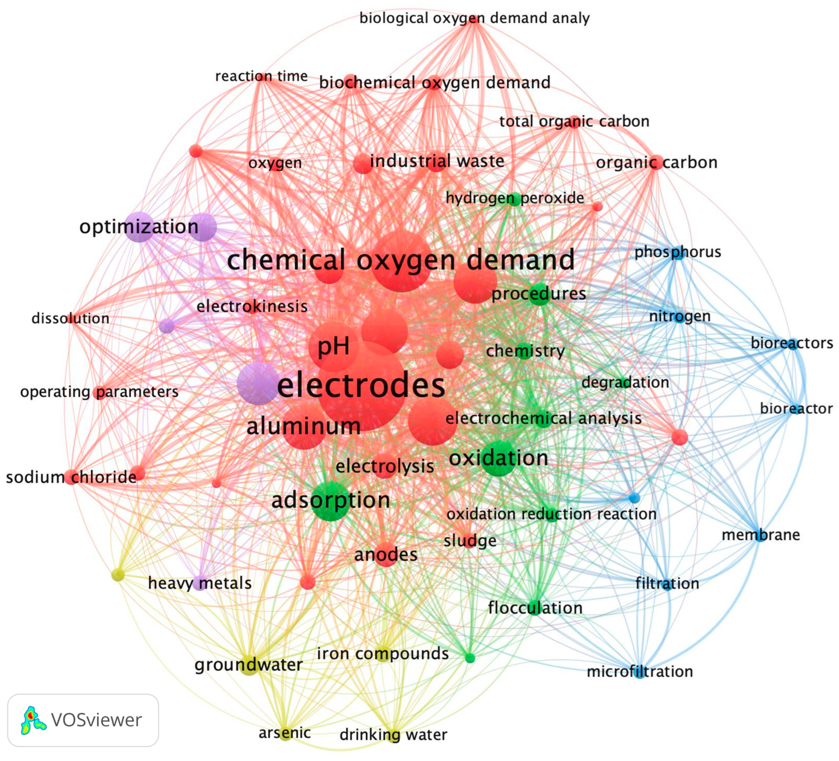
To better understand research trends in the field of EC, key terms in EC research papers (and review articles) from the past 5 years (2018–2022) were searched on the Scopus database and analyzed using VOSviewer software. By using the keywords of “electrocoagulation” and “wastewater treatment” or “water treatment” and limiting the document type to “article” or “review”, the language to “English”, and the publishing year to “2018 to 2022”, 1201 EC papers were yielded in the Scopus database. These papers were then selected manually again to exclude unrelated papers. A network map showing the resultant top 100 terms of co-occurrence is shown in Figure 4.
There are five clusters of terms of publication of EC for wastewater treatment, represented by different colors, which have been identified by the VOSviewer software (Figure 4). The size of the circles indicates the frequency of the terms in EC studies. The terms “electrodes” (532 occurrences), “chemical oxygen demand” (215 occurrences), “pH” (175 occurrences), “Iron” (173 occurrences), “aluminium” (156 occurrences), and “current density” (161 occurrences) were most frequently studied in the past 5 years. In general, the red cluster consists of terms primarily related to the treatment performance of EC with a focus on the role of “electrodes”, “pH”, “COD”, “Iron”, “aluminum” and “anodes”. Terms relating to the energy aspects of the EC process, such as “current density”, and “energy consumption” also occurred frequently. The green cluster includes terms related to the mechanisms of EC, such as “adsorption”, “oxidation”, “procedures”, “electrochemistry analysis”, “chemistry”, “flocculation”, and “oxidation-reduction reactions”. The blue cluster represents the integration of EC with other water treatment technologies, such as “bioreactors”, “membrane”, “filtration”, and “microfiltration”. The yellow cluster focuses on the removal of specific contaminants in portable water, such as “heavy metal”, “arsenic”, “iron compounds”, “ground water”, and “drinking water”. The purple cluster consists of terms related to the analysis and optimization of EC operations, including “optimization”, “response surface methodology”, and “kinetics”.
Based on the analysis through the VOS reviewer, these five clusters could represent the five main areas of research currently being conducted on EC at a global level: (1) pollutant removal performance and energy consumption, with a total weight of occurrences of 2719; (2) studies to understand the mechanisms of the EC reaction, with 705 total occurrences; (3) integration of EC with other treatment processes, with 351 occurrences; (4) the removal of emerging contaminants, with a total of 282 occurrences; and (5) analysis and optimization of operation, with 471 occurrences.
The development trends towards the evolution of EC studies could also be noticed from the highly cited articles. The top-cited experiment-based studies in the last 5 years were searched on Scopus; it can be found that most of them were conducted to assess the effectiveness of EC in removing various contaminants from water, including the removal of microplastics [77], phosphate [78], mental pollutants [79,80], and the treatment of textile wastewater [81,82,83] and oil wastewater [80]. In 2018, Perren et al. [77] looked at the use of EC to remove microplastic contaminants from artificial wastewater containing polyethylene microbeads and found that EC was effective with removal efficiencies above 90% across a range of pH values. The highest removal efficiency of 99.24% was observed at a pH of 7.5, and the optimal concentration of NaCl for the reactor was found to be between 0 and 2 g/L. Additionally, the specific mass-removal rate was highest for the lowest-tested current density of 11 A/m2, indicating that a low current density is more energy-efficient for microbead removal. After that, Hashim et al. [78] used a new aluminum-based electrochemical cell to remove phosphate from water, and it was found that 99% of phosphate could be removed within 60 min at certain operating conditions. Three studies focused on the treatment of textile wastewater were also conducted [81,82,83] and showed the removal of 86% to 98% of color, 82% and 83.5% of turbidity, and 18.6% to 59% of COD, respectively, under their optimum operation conditions.
The perspective of EC studies towards the integration of EC with other water/wastewater treatment processes, such as ozonation [84], electrochemical advanced-oxidation process (EAOP) [85,86], and microfiltration [80], was also highly interesting for researchers. Bilińska et al. [84] examined the use of EC and ozonation as a one-step and two-step process for the treatment of industrial textile wastewater and found that more than 95% of color removed could be achieved in a short treatment time. The EC and O3 combination was found to be more cost-effective when used in a two-step process, and the purified wastewater produced by the treatment process was suitable for recycling. When considering the coupling of EC with EAOPs for dyeing wastewater, Zazou et al. found that the sequential EC-EF treatment was the most effective process for the degradation of organic pollutants, achieving removals of 97% for TOC, 100% for turbidity, and 100% for color [86]. Additionally, the EAOP followed by EC was a better approach than EC followed by EAOP, as it yielded a higher COD reduction of 93.5% with a lower specific energy consumption and less sludge generated [85]. A study by Changmai et al. utilized ceramic membranes that were prepared locally to perform microfiltration with the aim of eliminating flocs produced during the electrocoagulation process. The results showed that 75–85% of the initial flux was lost when performing microfiltration on the samples that had undergone electrocoagulation [80].
4. New Developments
4.1. Emerging Pollutants Removal by EC
4.1.1. Removal of Microplastics
Plastic is a popular polymer material used in various industries because of its light weight, strength, durability, and low cost. A large amount of plastic waste is being discharged into the environment, creating microplastics (MPs) with particle sizes less than 5 mm in diameter [23,87,88,89]. Microplastics can be found in various sizes worldwide, mainly originating from household sewage discharge, plastic manufacturing, and plastic debris fragmentation [89]. Wastewater treatment plants are a significant contributor to microplastics release into the environment, as they cannot efficiently remove them, leading to their accumulation in aquatic ecosystems [89]. MPs cannot be completely degraded due to their polymeric structure and their ability to be easily transported between different habitats [89]. In water environments, planktonic and invertebrate organisms are highly susceptible to accumulating microplastics, which then transfer through the food chain and the human body, and may lead to physical harm, decreased nutritional value, and exposure to pathogens [89,90]. Additionally, raw plastics contain chemical additives such as phthalates, bisphenol A, and polybrominated diphenyl ethers, which can cause toxic effects when consumed by living organisms [89].
Coagulation-based processes have great potential for MPs separation from water/wastewater [88]. The potential benefit of using the EC process to remove MPs is its simple operation, high efficiency, and low cost [88,91]. While EC has been a well-studied area of research, there are relatively few studies specifically focused on MPs removal. These studies indicate that EC could effectively remove MPs, i.e., more than 90% removal in optimum reaction conditions from real wastewater [92,93,94,95] and artificial wastewater [77,96].
EC uses metal electrodes to generate coagulants in situ, which can adsorb charged pollutants and even degrade MPs. The main removal mechanisms of MPs by EC include:
- (1)
- Sorption, electrical neutralization, and flotation, whereby the positive charge on the surface of the flocculants allows for the adsorption of negatively charged ionic MPs. The production of H2 and O2 bubbles during the EC process could also help bring the flocs to the surface, where they can be removed through skimming [23].
- (2)
- Oxidation reaction, where the reactive chlorine species (RCS, such as ClO− and Cl2) and reactive oxygen species (ROS, such as O2, O2•−, H2O2, and OH−) and Fe(IV) generated on the anode accompanied by the metal-ion precipitation, can oxidize the MPs into small molecules of non-toxic substrates [23].
4.1.2. Removal of PFASs
Per- and polyfluoroalkyl substances (PFAS) are a group of synthetic chemicals comprised of a hydrophobic fluorinated alkyl chain at one end and a hydrophilic functional group at the other [97,98]. The high thermal and chemical stability owing to the strong C-F bonds, make PFAS extremely suitable in applications where they need to repel water and oil and resist friction [97] with over 4700 different compounds in use (e.g., Perfluorooctanoic acid (PFOA) and perfluorooctane sulfonic acid (PFOS)) [99]. PFAS are produced on a large scale for various industrial purposes, such as the production of textiles, paper, pesticides, leather, medical devices, metals, minerals, and oil, as well as for consumer applications like non-stick cookware, food packaging, cosmetics, paints, inks, surfactants, waterproof products, and firefighting foams [97]. They are known for their persistence, bioaccumulation, and occurrence in drinking-water sources and the effluent of wastewater treatment plants. A nationwide study in the US found PFAS in all 25 drinking-water treatment plants studied at levels exceeding the maximum contaminant levels in some state-level regulations [100]. Previous studies have reported that exposure to PFAS is associated with various acute and chronic human diseases [97,101,102], and some perfluoroalkyl carboxylic acids have demonstrated immunotoxicity, carcinogenicity, and hormonal disorder effects in animals [97,103,104].
EC has the ability to eliminate PFAS through either non-destructive phase separation or destructive oxidative pathways. Compared to other PFAS treatment methods that are destructive, such as sonolysis, ultraviolet (UV) advanced oxidation, advanced reduction, and photocatalysis, EC requires less energy input [105]. Most studies using EC to remove PFAS have concentrated on non-destructive methods that involve the sorption of PFAS to metal hydroxide flocs created using sacrificial electrodes [105]. Iron and aluminum are the commonly used electrodes, while zinc has shown greater PFOA removal compared to iron and aluminum [106]. PFAS sorption to hydroxides was primarily attributed to hydrophobic interactions between PFAS species and the metal hydroxide surface via multilayer sorption [106]. Moreover, studies suggest that EC can produce oxidation reactions through anode-surface oxidation, reactive iron intermediates, or Fenton processes (presuming there is H2O2 in the matrix) at low pH, which may lead to PFAS degradation [105]. Recent research has demonstrated the oxidative ability of iron-electrocoagulation for PFAS removal, which involves direct electron transfer and oxidant generation, leading to the production of shorter-chain PFAS compounds [107]. The removal rate was independent of pH, making it a potential oxidative process for drinking-water treatment under neutral conditions [19].
Wang et al. [108] found that using a stainless steel rod as the cathode was more effective than those using an aluminum rod as the cathode for the removal of PFOA. Hydroxide flocs generated in situ in the EC process in the presence of Cl−/NO3− could effectively remove PFOA from an aqueous solution (99.7%/98.1% and 98.9%/97.3%), while the PFOA removal ratios were lower in the presence of SO42− and CO32−/HCO3− (96.2%/4.1% and 7.4%/4.6%). The study also demonstrated that Zn0.61Al0.39(OH)2(CO3)0.195·xH2O and ZnO generated in situ in the electrocoagulation process using a zinc anode and aluminum/stainless steel rod cathode governed the sorption of PFOA. Liu et al. [109] found that 99.6% and 79.4% of PFOA could be removed by EC with Al-Zn electrodes from a simulated solution (1 mag/L PFOA) and natural groundwater in optimum conditions. PFOA contamination was found to be adsorbed on the flocs of Zn0.61Al0.39(OH)2(CO3)0.195·xH2O through the mechanism of adsorption bringing enmeshment, mainly resulting from the hydrophobic interaction of PFOA and Al-Zn hydroxide flocs. Kim et al. [107] found that an increase in the current density from 2.4 to 80.0 mA/cm2 in EC using an Fe electrode led to a significant increase in the removal efficiency of PFOA from 10.0 to 100.0% within 6 h. Formate (HCOO−) ions and three shorter-chain perfluorocarboxylates were observed as organic byproducts during the EC of PFOA, indicating that the C-C bond between C7F15 was firstly broken down and then degraded into short carbon-chain compounds by PFOA decomposition. Aside from metal electrodes, air cathodes have also been applied in EC for PFAS removal. Mu et al. [110] showed that EC with an air cathode could remove high PFOA concentrations (99.8%) with significantly less energy consumption than traditional electrocoagulation with aeration. At low PFOA concentrations, EC with an air cathode was found to be less effective 41.1 ± 11.6% than EC with aeration. PFOS removal rates were generally lower (76.4–88.5%) than PFOA but were better at low concentrations due to a higher hydrophobicity.
4.2. EC Powered by Bio-Current
4.2.1. Power Supply via Microbial Fuel Cells (MFCs)
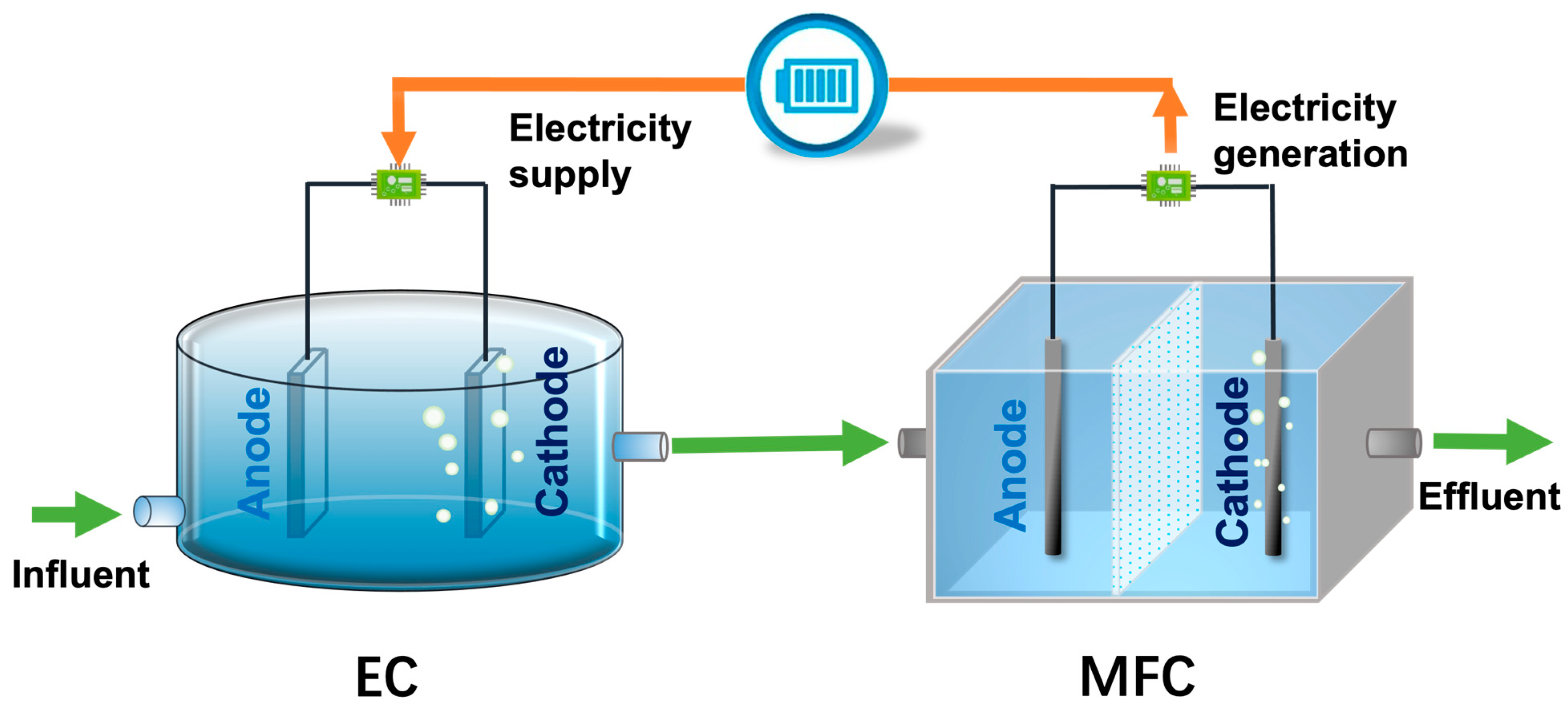
In recent years, bio-electrochemical systems (BESs) such as microbial fuel cells (MFCs) have received increased attention for their ability to simultaneously treat wastewater and generate electricity [111,112,113]. MFCs are a promising technology that can convert chemical energy in biomass or organic matter found in wastewater into electricity. It operates based on the principles of oxidation and reduction processes. They typically consist of two chambers: an anode chamber (anaerobic/anoxic) and a cathode chamber (aerobic/oxic), which are separated by a proton-exchange membrane or sufficient distance (Figure 5). MFCs facilitate the degradation of organics or pollutants at the anode and generate an electron flow through a series of redox potentials, where oxygen is reduced, and electricity is produced [112].
Despite the advantages of using wastewater to generate energy, the voltage produced by MFCs is limited. The maximum theoretical open-circuit voltage that can be generated is 1.14 V, which is the result of subtracting the oxygen redox potential (−0.32 V) from the NADH redox potential (+0.82 V) when oxygen is used as the cathode’s electron acceptor. However, in practical applications, the working voltage of the MFC is typically only between 0.2 V and 0.7 V. In order to increase the overall voltage, MFCs can be stacked together (i.e., linked together in series or parallel), resulting in a nearly additive increase in total voltage [114,115,116]. The stacking of pure MFCs has been well-demonstrated with a wide variety of examples of how the power generated could be reused [116]. MFC stacks could be classified in two ways: electrical stacking and hydraulic stacking, with the connection arrangement of either of these approaches being either series or parallel [116]. The resulting power output from the system can be used to run electronic appliances and sensors that require low levels of power. To improve the current output of MFCs, the internal resistance needs to be reduced [117,118]. In a stacked configuration, the internal resistance of the MFC is affected by factors such as transport resistance, kinetic resistance, and ohmic resistance [117,118].
There has been only a very limited number of studies that have attempted to use MFCs to power EC. The system configuration is schematically illustrated in Figure 5. Mei et al. (2019) explored the possibility of using an integrated EC and MFC stack (three MFCs connected in series) to not only remove contaminants but to achieve energy neutrality by using the electricity produced by the MFC stack to power the EC. Results show that the MFC stack-powered EC was able to remove 93% of oily organics, similar to the performance of an externally (DC) powered EC. The EC electrode area and distance were found to have a significant impact on current generation and contaminant removal [56]. Safwat et al. (2018) also investigated the potential for integrating MFCs and ECs into a single system for two types of wastewater treatment: synthetic wastewater and real municipal wastewater. In contrast to the study by Mei et al. (2019), which connected MFC stacks directly to EC via wires, this study employed two rechargeable batteries to store the electricity generated from the MFCs stacks (which were comprised of 6 cells connected in series). The batteries were then discharged once they were full, providing power to the EC. The results showed that the system was able to effectively remove COD, TDS, and TSS from both types of wastewater. The energy harvested from MFCs to power ECs was higher when using synthetic wastewater. While the initial capital cost of the integrated system is high, it is expected to significantly reduce operational costs compared to using ECs alone [57]. Nevertheless, the investigations referred to herein solely addressed the EC operations carried out for brief periods of 7 h and 1 h in batch mode. The research used various MFCs linked in series as energy sources, but there remains a gap in understanding the impact that different numbers and modes of MFC connections may have. Consequently, further research is imperative to study the energy pathways in MFCs and evaluate the EC system’s long-term performance.
4.2.2. Power Supply via EW
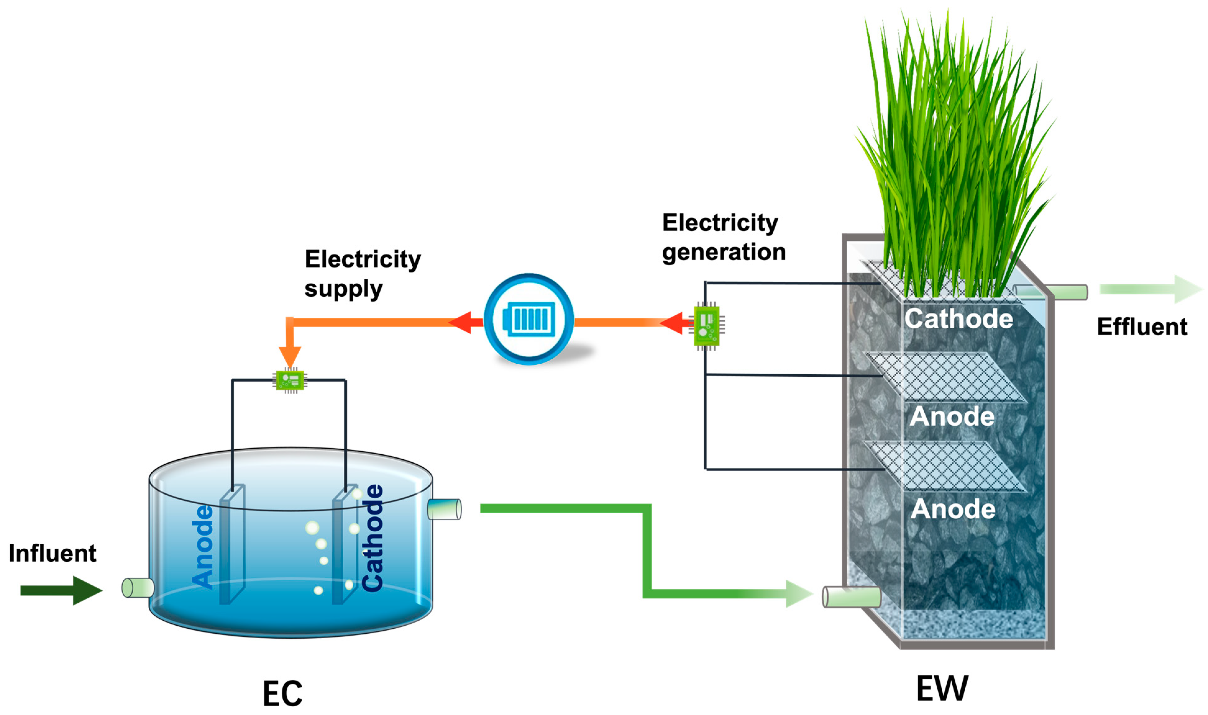
MFC has the ability to convert more than 90% of bioenergy into electrical energy [113,119]. This encourages the exploration of larger-scale MFC-based systems that can extend the technical and economic capability of MFCs [120]. The combination of a low-cost wastewater treatment technology, constructed wetlands (CW), with MFCs [121,122,123], has been termed CW-MFC [123,124], METland [125], bioelectrochemical-wetland [120] and electroactive wetland [112], and electro-wetland (EW) [126]. EW shares a similar configuration as MFCs, whereby the naturally existing stratified redox conditions in EW are highly consistent with the requirements for MFCs. EW typically consist of electrodes, substrate material, and plants (Figure 6). The cathode is typically placed in the aerobic zone or on the surface as an air cathode, while the anode is embedded deep in the anaerobic zone. Substances such as alum sludge, activated carbon, and graphite are the most commonly used materials and have been proven to improve the efficiency of these systems through biogeochemical processes [127]. Plants are also one of the key components in the system and are typically located in the cathode area, with their roots embedded in the substrate [128]. The electroactive bacteria presented in the system break down organic matter at the anode and produce electrons that flow through external electric wires to the cathode [112,123,127]. In the cathode area, oxygen is used as the most common electron acceptor. In reduction reactions at the cathode, hydrogen peroxide, a strong oxidizing substance, can be produced as a by-product and used to enhance the efficiency of pollutant removal [113]. This electron transfer creates a potential difference between the anaerobic and aerobic regions, which allows for electricity generation in EWs [112,113,121].
Given the sustainability and wastewater treatment capabilities of EWs, it is important to carefully consider which applications of this ‘green energy’ technology would be suitable for retrofitting existing EWs. During the last few years, the power output of EWs has been significantly improved [126,129,130]. However, the volumetric power densities of EWs are still in the milliwatts range [131]. The power density of EWs tends to be lower than MFCs, as a result of the large ohmic losses due to the internal resistance increment and the electrode potential losses (activation losses) [132]. Therefore, a greater electricity-generation performance may be achieved through the direct utilization of the bioenergy produced. Some researchers have suggested that the limited energy recovered from wastewater in EWs could potentially be used to power small electronic devices [57,133], such as bioelectrochemical/electrochemical systems. Xu et al. (2019) also mentioned that the energy produced by EW could possibly offset the energy consumed in the process, such as supporting bio-current to in situ or ex situ electrically related treatment process for electro-Fenton or bio-electrolysis process.
The application of EWs as power sources is currently very limited, with only two related studies reported. A proposed system configuration is schematically illustrated in Figure 6. Zhang et al. [134] used EWs stacks (2 cells connected in series) to power a bio-electrochemical system (BES) for sulfamethoxazole (SMX) removal. The results showed that EWs could provide enough stable electricity (between 0.84 and 1.01 volts) to support the BES in breaking down SMX without the need for additional energy. The low current levels powered by CW-MFCs did not impact the degradation products but did increase the rate of SMX removal [134]. Another study was conducted by Srivastava et al. [135], which explored the use of a power management system (PMS) to store the power output of EWs and boost voltage to power a small air pump for providing oxygen in the cathode area of the EW system. With intermittent aeration, the maximum power generation by one of the EW increased from 54.6 W to 90 W, and ammonium removal increased by 10% [135].
EC applies the micro-electrical current to remove contaminants in an aqueous environment and therefore presents the best possibility to use the power generated from EW [136]. It is reasonable to assume that the utilization of EW for powering EC could be an effective way to reduce not only the cost of energy consumed by EC but also to maintain the high treatment performance of both processes.
4.3. Unilizaiton of Power Management Systems in EC
A power management system (PMS) is an electronic circuit that harvests energy from an MFC/EW and shapes it into a usable form [137]. The system could capture and store the unstable and limited power output from MFCs/EWs and boost voltage to a relatively higher and constant level in a certain range [116,138], and subsequently prevent voltage reversal occurring in stacked MFCs/EWs during long-time reactions [138]. The system usually consists of a harvesting system, including maximum power point (MPP) tracking and an energy storage unit by means of supercapacitors [135]. It is different from external resistors, which only show energy output potential but do not capture usable energy, as the current flowing through the resistor is lost as heat [137,138]. Thus the combination of PMS with MFC-based technology is essential for the functioning of EC and provides the possibility of creating a self-sufficient power supply for EC throughout the duration of a long-term reaction.
As mentioned before, a rise in the current density in EC leads to more efficient removal. The current density also affects the bubble production rate and size [13,60,61]. A standard potential (1.229 V) between the cathode and anode is necessary to carry out water electrolysis in EC, resulting in floatation and enhanced treatment performance. Hence when considering using MFC/EW to power EC, the working voltage has to be sufficient to ensure the treatment performance of EC. Considering that the power generated from a single cell of EW is limited, using a stack of modular EWs could potentially increase the total voltage generated and make it sufficient to power low-energy devices [57,139]. However, the bio-current generated in MFCs/EWs relies heavily on the bioactivities of bacteria, which vary with reaction performance conditions. Increased power production cannot be achieved simply by constructing larger MFCs/EWs or connecting MFCs/EWs in series or parallel, owing to the non-linear characteristics of MFCs/EWs [138]. Stacked modular EWs often experience an unpredictable voltage reversal when some of the unit cells act as power-supplying batteries and others as power-consuming loads [140,141,142].
The PMS has been used with MFCs in previous studies for practical usage. Wang et al. [138] gave a detailed description of these updated PMS for pure MFCs, and summarized them as three energy-harvesting processes: (a) a concise process from MFCs (energy generator) to electronic devices (energy consumer); (b) a classic and widely adopted PMS circuit composed of a charge pump and a boost converter with accessory components; (c) a two-layer energy-harvesting scheme, which is operated in alternative ‘charge’ and ‘discharge’ phases [138].
So far, the use of PMS with EWs is very limited, and there have only been two related studies published. Xu et al. [129] first reported tests of a novel strategy of PMS, called a capacitator-engaged duty cycling (CDC) strategy, to harvest energy from an open-air bio-cathode EW. An investigation was conducted to compare the energy harvest performance of three working regimes: (1) continuous loading mode (CL), a continuous connection of external resistor to the circuit; (2) duty-cycling mode (DC), intermittent loading of an external resistor; and (3) CDC, intermittent consumption of energy stored in three external capacitors (4700 ) through an external resistor. The results indicate that the CDC strategy (intermittent energy consumption) leads to a 19.81% higher effective charge than the CL (continuous loading) mode at a duty cycle value of 31.6%. With a lower duty cycle of 20%, the total charge harvested increases by 25.0%. This study is the first to use PMS to harvest energy in EW systems, which have not previously dealt with the application of energy from EW. Srivastava et al. [135] unitized a PMS with two supercapacitors (55 F) to harvest and boost voltage from EWs, and to power a small air pump to provide oxygen to the cathode area in EWs. With the connection of PMS, the voltage of EWs (394 ± 53 mV and 307 ± 34 mV) was boosted to 1.7 V to power the air pump. The ammonium removal and power generation of EW were subsequently increased. However, the initial energy harvested took a long time (60 days) to reach the start-up voltage of 1.5 V. Once 1.5 V was reached, the air pump was connected to the circuit, but every 60 s of aeration required 6 days of harvest time to withdraw power from the EW. Further studies are needed to focus on the optimization of the PMS circuits, including smaller supercapacitors and a lower start-up voltage to improve the system.
5. Research Gap and Further Research Direction of EC
Considering the complexities and high investments in supplying commercial energy to a field site, the application of EC in remote locations is limited [136]. Previous studies have explored renewable energy sources, such as photovoltaic energy, wind energy, or hydroelectricity. However, the power-generation rate of these energy systems is largely influenced by natural conditions, such as geographical latitude, sunlight intensity, wind speed, gravitational potential, land area, hydraulic loading, and other similar factors. The high cost of implementation of such technologies has limited their application [66], especially for powering electrochemical treatment processes like EC, which has only limited lab-scale studies published. Therefore, integration with compatible and economical bioenergy technologies (e.g., MFCs or EW) seems necessary and important. Compared with other power sources (e.g., fossil fuels, solar photovoltaic, wind turbines, hydroelectricity power), EW/MFC could recycle the ‘green’ energy in wastewater and output as electricity energy, which owns more advantages of sustainability, easy construction/maintaining, and lower investment. Therefore, EW/MFC may act as a capable and green energy source of EC for water/wastewater treatment in a field or rural area. There are only a few studies of EC powered by MFC and no published studies of EW powering EC. As such, further development is highly desirable for this proposed approach. The PMS and stacking EWs could be considered to manage and improve the energy output. Furthermore, energy flow pathways between the electron accepters and electron donor and their contribution on pollutants removal and power generation/consumption in systems should be identified.
EC systems are designed to remove pollutants using electrochemical processes only, without relying on biological processes. While this approach is effective in removing many pollutants, it may face practical limitations when it comes to removing new biodegradable and soluble organic pollutants. To overcome this limitation, the EC process can be combined with other biological treatment technologies to improve the efficiency of pollutant removal. It is crucial to select the appropriate combination of treatments to ensure optimal results. Systems that rely on bio-electrochemical processes, such as EW or MFC, can serve as suitable external power sources for EC systems, but they are susceptible to toxic or recalcitrant pollutants. Hence, combining EC and EW/MFC systems into a self-powered hybrid system can effectively enhance water-treatment performance and achieve energy neutrality in a single treatment process (Figure 5 and Figure 6). This combination of processes can be utilized to optimize treatment efficiency by allowing the removal of toxic pollutants before the EW/MFC stage, followed by the removal of biodegradable contaminants that may still be present after the EC pre-treatment stage. The proposed method could also serve as a sustainable alternative for treating complex wastewater, especially in scenarios where electricity is scarce or when dealing with field applications. At present, there is a dearth of literature on the feasibility of a hybrid EC-EW/MFC system. Hence, it may be necessary to conduct a feasibility study on the combination of these technologies. To ensure protection of the environment and human health, it is crucial to focus on the removal of emerging pollutants, such as antibiotics, pesticides, surfactants, and endocrine-disrupting compounds (EDCs). These compounds are likely to be subject to increasingly stringent water treatment regulations and thus require further attention.
6. Conclusions
EC is a highly efficient and environmentally friendly technology for removing contaminants from water and wastewater. This review offers valuable insights into the current state of EC technology and highlights opportunities for further research and development. The paper presents an overview of the advantages and limitations, fundamental mechanisms, and operational factors of EC. To determine the current state of EC research, a comprehensive literature search was conducted using the Scopus database, and relevant keywords were analyzed and classified using VOSviewer software. The review highlights new developments in EC, including the removal of emerging pollutants, the use of MFC and EW for power supply, and the application of PMS in EC. The paper concludes with a discussion of future research opportunities, including:
- Optimizing operating conditions of EC to achieve both low power consumption and high removal efficiency;
- Exploring the techno-economic feasibility of coupling EC and EW/MFC systems;
- Identifying the energy pathways and energy application/management of hybrid systems;
- Focusing on the effective removal of emerging pollutants using a hybrid EC system.
Author Contributions
Conceptualization, Y.M. and Y.Z.; literature review, Y.M. and Y.Z.; software, Y.M.; formal analysis, Y.M.; writing—original draft preparation, Y.M.; writing—review and editing, Y.Z. and S.C.; visualization, Y.M., Y.Z. and S.C.; supervision, Y.Z. and S.C. All authors have read and agreed to the published version of the manuscript.
Funding
The first author acknowledges financial support from the China Scholarship Council and University College Dublin, Ireland, for the Ph.D. scholarship.
Data Availability Statement
All data presented in this study will be available upon request to the corresponding author via email.
Conflicts of Interest
The authors declare that they have no known competing financial interests or personal relationships that could have appeared to influence the work reported in this paper.
References
- United Nations. The Sustainable Development Goals Report 2022; United Nations: New York, NY, USA, 2022. [Google Scholar]
- WHO. World Health Statistics 2022 (Monitoring Health of the SDGs); WHO: Geneva, Switzerland, 2022; ISBN 9789240051140. [Google Scholar]
- Ingelsson, M.; Yasri, N.; Roberts, E.P.L. Electrode Passivation, Faradaic Efficiency, and Performance Enhancement Strategies in Electrocoagulation—A Review. Water Res. 2020, 187, 116433. [Google Scholar] [CrossRef] [PubMed]
- Almukdad, A.; Hafiz, M.; Yasir, A.T.; Alfahel, R.; Hawari, A.H. Unlocking the Application Potential of Electrocoagulation Process through Hybrid Processes. J. Water Process Eng. 2021, 40, 101956. [Google Scholar] [CrossRef]
- Moussa, D.T.; El-Naas, M.H.; Nasser, M.; Al-Marri, M.J. A Comprehensive Review of Electrocoagulation for Water Treatment: Potentials and Challenges. J. Environ. Manag. 2017, 186, 24–41. [Google Scholar] [CrossRef]
- Vik, E.A.; Carlson, D.A.; Eikum, A.S.; Gjessing, E.T. Electrocoagulation of Potable Water. Water Res. 1984, 18, 1355–1360. [Google Scholar] [CrossRef]
- Dura, A. Electrocoagulation for Water Treatment: The Removal of Pollutants Using Aluminium Alloys, Stainless Steels and Iron Anodes; National University of Ireland: Maynooth, Ireland, 2013; pp. 1–306. [Google Scholar]
- Song, P.; Yang, Z.; Zeng, G.; Yang, X.; Xu, H.; Wang, L.; Xu, R.; Xiong, W.; Ahmad, K. Electrocoagulation Treatment of Arsenic in Wastewaters: A Comprehensive Review. Chem. Eng. J. 2017, 317, 707–725. [Google Scholar] [CrossRef]
- Abdulhadi, B.; Kot, P.; Hashim, K.; Shaw, A.; Muradov, M.; Al-Khaddar, R. Continuous-Flow Electrocoagulation (EC) Process for Iron Removal from Water: Experimental, Statistical and Economic Study. Sci. Total Environ. 2021, 760, 143417. [Google Scholar] [CrossRef] [PubMed]
- Sari-Erkan, H. Wastewater Treatment from the Biodiesel Production Using Waste Cooking Oil by Electrocoagulation: A Multivariate Approach. Water Sci. Technol. 2019, 79, 2366–2377. [Google Scholar] [CrossRef] [PubMed]
- Criado, S.P.; Gonçalves, M.J.; Ballod Tavares, L.B.; Bertoli, S.L. Optimization of Electrocoagulation Process for Disperse and Reactive Dyes Using the Response Surface Method with Reuse Application. J. Clean. Prod. 2020, 275, 122690. [Google Scholar] [CrossRef]
- Ni’am, M.F.; Othman, F. Experimental Design of Electrocoagulation and Magnetic Technology for Enhancing Suspended Solids Removal from Synthetic Wastewater. Int. J. Sci. Eng. 2014, 7, 178–192. [Google Scholar] [CrossRef] [Green Version]
- Rahman, N.A.; Jol, C.J.; Linus, A.A.; Ismail, V. Emerging Application of Electrocoagulation for Tropical Peat Water Treatment: A Review. Chem. Eng. Process.-Process Intensif. 2021, 165, 108449. [Google Scholar] [CrossRef]
- McBeath, S.T.; Nouri-Khorasani, A.; Mohseni, M.; Wilkinson, D.P. In-Situ Determination of Current Density Distribution and Fluid Modeling of an Electrocoagulation Process and Its Effects on Natural Organic Matter Removal for Drinking Water Treatment. Water Res. 2020, 171, 115404. [Google Scholar] [CrossRef] [PubMed]
- Zeng, J.; Ji, M.; Zhao, Y.; Pedersen, T.H.; Wang, H. Optimization of Electrocoagulation Process Parameters for Enhancing Phosphate Removal in a Biofilm-Electrocoagulation System. Water Sci. Technol. 2021, 83, 2560–2574. [Google Scholar] [CrossRef] [PubMed]
- Bakshi, A.; Verma, A.K.; Dash, A.K. Electrocoagulation for Removal of Phosphate from Aqueous Solution: Statistical Modeling and Techno-Economic Study. J. Clean. Prod. 2020, 246, 118988. [Google Scholar] [CrossRef]
- Priyadarshini, M.; Ahmad, A.; Das, S.; Ghangrekar, M.M. Application of Innovative Electrochemical and Microbial Electrochemical Technologies for the Efficacious Removal of Emerging Contaminants from Wastewater: A Review. J. Environ. Chem. Eng. 2022, 10, 108230. [Google Scholar] [CrossRef]
- Mousazadeh, M.; Niaragh, E.K.; Usman, M.; Khan, S.U.; Sandoval, M.A.; Al-Qodah, Z.; Khalid, Z.B.; Gilhotra, V.; Emamjomeh, M.M. A Critical Review of State-of-the-Art Electrocoagulation Technique Applied to COD-Rich Industrial Wastewaters. Environ. Sci. Pollut. Res. 2021, 28, 43143–43172. [Google Scholar] [CrossRef] [PubMed]
- Garcia-Segura, S.; Eiband, M.M.S.G.; de Melo, J.V.; Martínez-Huitle, C.A. Electrocoagulation and Advanced Electrocoagulation Processes: A General Review about the Fundamentals, Emerging Applications and Its Association with Other Technologies. J. Electroanal. Chem. 2017, 801, 267–299. [Google Scholar] [CrossRef] [Green Version]
- Ghaffarian Khorram, A.; Fallah, N. Comparison of Electrocoagulation and Photocatalytic Process for Treatment of Industrial Dyeing Wastewater: Energy Consumption Analysis. Environ. Prog. Sustain. Energy 2020, 39, 13288. [Google Scholar] [CrossRef]
- Akyol, A.; Can, O.T.; Demirbas, E.; Kobya, M. A Comparative Study of Electrocoagulation and Electro-Fenton for Treatment of Wastewater from Liquid Organic Fertilizer Plant. Sep. Purif. Technol. 2013, 112, 11–19. [Google Scholar] [CrossRef]
- Gao, T.; Lin, J.; Zhang, K.; Padervand, M.; Zhang, Y.; Zhang, W.; Shi, M.; Wang, C. Porous Defective Bi/Bi3NbO7 Nanosheets for Efficient Photocatalytic NO Removal under Visible Light. Processes 2023, 11, 115. [Google Scholar] [CrossRef]
- Liu, F.; Zhang, C.; Li, H.; Offiong, N.-A.O.; Bi, Y.; Zhou, R.; Ren, H. A Systematic Review of Electrocoagulation Technology Applied for Microplastics Removal in Aquatic Environment. Chem. Eng. J. 2023, 456, 141078. [Google Scholar] [CrossRef]
- Padervand, M.; Rhimi, B.; Wang, C. One-Pot Synthesis of Novel Ternary Fe3N/Fe2O3/C3N4 Photocatalyst for Efficient Removal of Rhodamine B and CO2 Reduction. J. Alloys Compd. 2021, 852, 156955. [Google Scholar] [CrossRef]
- Belongia, B.M.; Haworth, P.D.; Baygents, J.C.; Raghavan, S. Treatment of Alumina and Silica Chemical Mechanical Polishing Waste by Electrodecantation and Electrocoagulation. J. Electrochem. Soc. 1999, 146, 4124. [Google Scholar] [CrossRef]
- Rahman, N.A.; Muhammad Firdaus Kumar, N.K.; Gilan, U.J.; Jihed, E.E.; Phillip, A.; Linus, A.A.; Nen@Shahinan, D.; Ismail, V. Kinetic Study & Statistical Modelling of Sarawak Peat Water Electrocoagulation System Using Copper and Aluminium Electrodes. J. Appl. Sci. Process Eng. 2020, 7, 439–456. [Google Scholar] [CrossRef]
- Kumari, S.; Kumar, R.N. River Water Treatment Using Electrocoagulation for Removal of Acetaminophen and Natural Organic Matter. Chemosphere 2021, 273, 128571. [Google Scholar] [CrossRef] [PubMed]
- Snehi, S.; Singh, H.; Priya, T.; Mishra, B.K. Understanding the Natural Organic Matter Removal Mechanism from Mine and Surface Water through the Electrocoagulation Method. J. Water Supply Res. Technol.-AQUA 2019, 68, 523–534. [Google Scholar] [CrossRef]
- Ulu, F.; Gengec, E.; Kobya, M. Removal of Natural Organic Matter from Lake Terkos by EC Process: Studying on Removal Mechanism by Floc Size and Zeta Potential Measurement and Characterization by HPSEC Method. J. Water Process Eng. 2019, 31, 100831. [Google Scholar] [CrossRef]
- El-Ghenymy, A.; Alsheyab, M.; Khodary, A.; Sirés, I.; Abdel-Wahab, A. Corrosion Behavior of Pure Titanium Anodes in Saline Medium and Their Performance for Humic Acid Removal by Electrocoagulation. Chemosphere 2020, 246, 125674. [Google Scholar] [CrossRef]
- Hasani, G.; Maleki, A.; Daraei, H.; Ghanbari, R.; Safari, M.; McKay, G.; Yetilmezsoy, K.; Ilhan, F.; Marzban, N. A Comparative Optimization and Performance Analysis of Four Different Electrocoagulation-Flotation Processes for Humic Acid Removal from Aqueous Solutions. Process Saf. Environ. Prot. 2019, 121, 103–117. [Google Scholar] [CrossRef]
- Chellam, S.; Sari, M.A. Aluminum Electrocoagulation as Pretreatment during Microfiltration of Surface Water Containing NOM: A Review of Fouling, NOM, DBP, and Virus Control. J. Hazard. Mater. 2016, 304, 490–501. [Google Scholar] [CrossRef] [Green Version]
- Ensano, B.M.B.; Borea, L.; Naddeo, V.; Belgiorno, V.; de Luna, M.D.G.; Balakrishnan, M.; Ballesteros, F.C. Applicability of the Electrocoagulation Process in Treating Real Municipal Wastewater Containing Pharmaceutical Active Compounds. J. Hazard. Mater. 2019, 361, 367–373. [Google Scholar] [CrossRef]
- Choi, A.E.S.; Futalan, C.C.M.; Yee, J.-J. Fuzzy Optimization for the Removal of Uranium from Mine Water Using Batch Electrocoagulation: A Case Study. Nucl. Eng. Technol. 2020, 52, 1471–1480. [Google Scholar] [CrossRef]
- Nariyan, E.; Sillanpää, M.; Wolkersdorfer, C. Uranium Removal from Pyhäsalmi/Finland Mine Water by Batch Electrocoagulation and Optimization with the Response Surface Methodology. Sep. Purif. Technol. 2018, 193, 386–397. [Google Scholar] [CrossRef]
- Omwene, P.I.; Kobya, M.; Can, O.T. Phosphorus Removal from Domestic Wastewater in Electrocoagulation Reactor Using Aluminium and Iron Plate Hybrid Anodes. Ecol. Eng. 2018, 123, 65–73. [Google Scholar] [CrossRef]
- Fajardo, A.S.; Rodrigues, R.F.; Martins, R.C.; Castro, L.M.; Quinta-Ferreira, R.M. Phenolic Wastewaters Treatment by Electrocoagulation Process Using Zn Anode. Chem. Eng. J. 2015, 275, 331–341. [Google Scholar] [CrossRef]
- S.I. No. 122/2014-European Union (Drinking Water) Regulations 2014. Available online: https://www.irishstatutebook.ie/eli/2014/si/122/made/en/print (accessed on 11 January 2023).
- Ghosh, D.; Medhi, C.R.; Purkait, M.K. Treatment of Fluoride Containing Drinking Water by Electrocoagulation Using Monopolar and Bipolar Electrode Connections. Chemosphere 2008, 73, 1393–1400. [Google Scholar] [CrossRef]
- Das, P.P.; Sharma, M.; Purkait, M.K. Recent Progress on Electrocoagulation Process for Wastewater Treatment: A Review. Sep. Purif. Technol. 2022, 292, 121058. [Google Scholar] [CrossRef]
- Demirci, Y.; Pekel, L.C.; Alpbaz, M. Investigation of Different Electrode Connections in Electrocoagulation of Textile Wastewater Treatment. Int. J. Electrochem. Sci. 2015, 10, 2685–2693. [Google Scholar]
- Sahu, O.; Mazumdar, B.; Chaudhari, P.K. Treatment of Wastewater by Electrocoagulation: A Review. Environ. Sci. Pollut. Res. 2014, 21, 2397–2413. [Google Scholar] [CrossRef]
- Thiam, A.; Zhou, M.; Brillas, E.; Sirés, I. Two-Step Mineralization of Tartrazine Solutions: Study of Parameters and by-Products during the Coupling of Electrocoagulation with Electrochemical Advanced Oxidation Processes. Appl. Catal. B Environ. 2014, 150–151, 116–125. [Google Scholar] [CrossRef]
- Abdel-Aziz, M.H.; El-Ashtoukhy, E.-S.Z.; Zoromba, M.S.; Bassyouni, M.; Sedahmed, G.H. Removal of Nitrates from Water by Electrocoagulation Using a Cell with Horizontally Oriented Al Serpentine Tube Anode. J. Ind. Eng. Chem. 2020, 82, 105–112. [Google Scholar] [CrossRef]
- Dura, A.; Breslin, C.B. The Removal of Phosphates Using Electrocoagulation with Al-Mg Anodes. J. Electroanal. Chem. 2019, 846, 113161. [Google Scholar] [CrossRef]
- Hu, C.Y.; Lo, S.L.; Kuan, W.H. Effects of Co-Existing Anions on Fluoride Removal in Electrocoagulation (EC) Process Using Aluminum Electrodes. Water Res. 2003, 37, 4513–4523. [Google Scholar] [CrossRef] [PubMed]
- Lu, J.; Zhang, P.; Li, J. Electrocoagulation Technology for Water Purification: An Update Review on Reactor Design and Some Newly Concerned Pollutants Removal. J. Environ. Manag. 2021, 296, 113259. [Google Scholar] [CrossRef] [PubMed]
- Bian, Y.; Ge, Z.; Albano, C.; Lobo, F.L.; Ren, Z.J. Oily Bilge Water Treatment Using DC/AC Powered Electrocoagulation. Environ. Sci. Water Res. Technol. 2019, 5, 1654–1660. [Google Scholar] [CrossRef]
- Donneys-Victoria, D.; Marriaga-Cabrales, N.; Machuca-Martínez, F.; Benavides-Guerrero, J.; Cloutier, S.G. Indigo Carmine and Chloride Ions Removal by Electrocoagulation. Simultaneous Production of Brucite and Layered Double Hydroxides. J. Water Process Eng. 2020, 33, 101106. [Google Scholar] [CrossRef]
- Bao, J.; Yu, W.-J.; Liu, Y.; Wang, X.; Liu, Z.-Q.; Duan, Y.-F. Removal of Perfluoroalkanesulfonic Acids (PFSAs) from Synthetic and Natural Groundwater by Electrocoagulation. Chemosphere 2020, 248, 125951. [Google Scholar] [CrossRef] [PubMed]
- Kamaraj, R.; Ganesan, P.; Lakshmi, J.; Vasudevan, S. Removal of Copper from Water by Electrocoagulation Process—Effect of Alternating Current (AC) and Direct Current (DC). Environ. Sci. Pollut. Res. 2013, 20, 399–412. [Google Scholar] [CrossRef]
- Mansoorian, H.J.; Mahvi, A.H.; Jafari, A.J. Removal of Lead and Zinc from Battery Industry Wastewater Using Electrocoagulation Process: Influence of Direct and Alternating Current by Using Iron and Stainless Steel Rod Electrodes. Sep. Purif. Technol. 2014, 135, 165–175. [Google Scholar] [CrossRef]
- Nawarkar, C.J.; Salkar, V.D. Solar Powered Electrocoagulation System for Municipal Wastewater Treatment. Fuel 2019, 237, 222–226. [Google Scholar] [CrossRef]
- Jeon, S.-B.; Kim, S.; Park, S.-J.; Seol, M.-L.; Kim, D.; Chang, Y.K.; Choi, Y.-K. Self-Powered Electro-Coagulation System Driven by a Wind Energy Harvesting Triboelectric Nanogenerator for Decentralized Water Treatment. Nano Energy 2016, 28, 288–295. [Google Scholar] [CrossRef]
- Ganiyu, S.O.; Martínez-Huitle, C.A.; Rodrigo, M.A. Renewable Energies Driven Electrochemical Wastewater/Soil Decontamination Technologies: A Critical Review of Fundamental Concepts and Applications. Appl. Catal. B Environ. 2020, 270, 118857. [Google Scholar] [CrossRef]
- Mei, X.; Wang, H.; Hou, D.; Lobo, F.L.; Xing, D.; Ren, Z.J. Shipboard Bilge Water Treatment by Electrocoagulation Powered by Microbial Fuel Cells. Front. Environ. Sci. Eng. 2019, 13, 53. [Google Scholar] [CrossRef]
- Safwat, S.M. Coupling Microbial Fuel Cells with Electrocoagulation Cells to Form an Integrated System for Wastewater Treatment. Pol. J. Environ. Stud. 2018, 28, 1909–1915. [Google Scholar] [CrossRef] [PubMed]
- Cho, H.; Kim, I.; Park, J.; Kim, D. A Waterwheel Hybrid Generator with Disk Triboelectric Nanogenerator and Electromagnetic Generator as a Power Source for an Electrocoagulation System. Nano Energy 2022, 95, 107048. [Google Scholar] [CrossRef]
- Tegladza, I.D.; Xu, Q.; Xu, K.; Lv, G.; Lu, J. Electrocoagulation Processes: A General Review about Role of Electro-Generated Flocs in Pollutant Removal. Process Saf. Environ. Prot. 2021, 146, 169–189. [Google Scholar] [CrossRef]
- Kumari, S.; Kumar, R.N. River Water Treatment by Continuous Electrocoagulation: Insights into Removal of Acetaminophen, and Natural Organic Matter. Water Supply 2022, 22, 4055–4066. [Google Scholar] [CrossRef]
- Liu, Y.; Zhang, X.; Jiang, W.M.; Wu, M.R.; Li, Z.H. Comprehensive Review of Floc Growth and Structure Using Electrocoagulation: Characterization, Measurement, and Influencing Factors. Chem. Eng. J. 2021, 417, 129310. [Google Scholar] [CrossRef]
- Chen, M.; Dollar, O.; Shafer-Peltier, K.; Randtke, S.; Waseem, S.; Peltier, E. Boron Removal by Electrocoagulation: Removal Mechanism, Adsorption Models and Factors Influencing Removal. Water Res. 2020, 170, 115362. [Google Scholar] [CrossRef]
- Han, N.; Huang, G.; An, C.; Zhao, S.; Yao, Y.; Fu, H.; Li, W. Removal of Sulfonated Humic Acid through a Hybrid Electrocoagulation-Ultrafiltration Process. Ind. Eng. Chem. Res. 2015, 54, 5793–5801. [Google Scholar] [CrossRef]
- Zhang, H.; Wu, B.; Li, X.; Zhang, X.; Wang, Y. Electrocoagulation Treatment of Shale Gas Drilling Wastewater: Performance and Statistical Optimization. Sci. Total Environ. 2021, 794, 148436. [Google Scholar] [CrossRef]
- Martínez-Huitle, C.A.; Rodrigo, M.A.; Sirés, I.; Scialdone, O. Single and Coupled Electrochemical Processes and Reactors for the Abatement of Organic Water Pollutants: A Critical Review. Chem. Rev. 2015, 115, 13362–13407. [Google Scholar] [CrossRef]
- Abraham, T.; Luthra, A. Socio-Economic & Technical Assessment of Photovoltaic Powered Membrane Desalination Processes for India. Desalination 2011, 268, 238–248. [Google Scholar] [CrossRef]
- Matteson, M.J.; Dobson, R.L.; Glenn, R.W.; Kukunoor, N.S.; Waits, W.H.; Clayfield, E.J. Electrocoagulation and Separation of Aqueous Suspensions of Ultrafine Particles. Colloids Surfaces A Physicochem. Eng. Asp. 1995, 104, 101–109. [Google Scholar] [CrossRef]
- Karhu, M.; Kuokkanen, V.; Kuokkanen, T.; Rämö, J. Bench Scale Electrocoagulation Studies of Bio Oil-in-Water and Synthetic Oil-in-Water Emulsions. Sep. Purif. Technol. 2012, 96, 296–305. [Google Scholar] [CrossRef]
- Kobya, M.; Can, O.T.; Bayramoglu, M. Treatment of Textile Wastewaters by Electrocoagulation Using Iron and Aluminum Electrodes. J. Hazard. Mater. 2003, 100, 163–178. [Google Scholar] [CrossRef] [PubMed]
- Karimifard, S.; Alavi Moghaddam, M.R. Application of Response Surface Methodology in Physicochemical Removal of Dyes from Wastewater: A Critical Review. Sci. Total Environ. 2018, 640–641, 772–797. [Google Scholar] [CrossRef] [PubMed]
- Samsami, S.; Mohamadi, M.; Sarrafzadeh, M.-H.; Rene, E.R.; Firoozbahr, M. Recent Advances in the Treatment of Dye-Containing Wastewater from Textile Industries: Overview and Perspectives. Process Saf. Environ. Prot. 2020, 143, 138–163. [Google Scholar] [CrossRef]
- Peng, H.; Guo, J. Removal of Chromium from Wastewater by Membrane Filtration, Chemical Precipitation, Ion Exchange, Adsorption Electrocoagulation, Electrochemical Reduction, Electrodialysis, Electrodeionization, Photocatalysis and Nanotechnology: A Review. Environ. Chem. Lett. 2020, 18, 2055–2068. [Google Scholar] [CrossRef]
- Shahedi, A.; Darban, A.K.; Taghipour, F.; Jamshidi-Zanjani, A. A Review on Industrial Wastewater Treatment via Electrocoagulation Processes. Curr. Opin. Electrochem. 2020, 22, 154–169. [Google Scholar] [CrossRef]
- Tahreen, A.; Jami, M.S.; Ali, F. Role of Electrocoagulation in Wastewater Treatment: A Developmental Review. J. Water Process Eng. 2020, 37, 101440. [Google Scholar] [CrossRef]
- Kobya, M.; Soltani, R.D.C.; Omwene, P.I.; Khataee, A. A Review on Decontamination of Arsenic-Contained Water by Electrocoagulation: Reactor Configurations and Operating Cost along with Removal Mechanisms. Environ. Technol. Innov. 2020, 17, 100519. [Google Scholar] [CrossRef]
- Zaied, B.K.; Rashid, M.; Nasrullah, M.; Zularisam, A.W.; Pant, D.; Singh, L. A Comprehensive Review on Contaminants Removal from Pharmaceutical Wastewater by Electrocoagulation Process. Sci. Total Environ. 2020, 726, 138095. [Google Scholar] [CrossRef] [PubMed]
- Perren, W.; Wojtasik, A.; Cai, Q. Removal of Microbeads from Wastewater Using Electrocoagulation. ACS Omega 2018, 3, 3357–3364. [Google Scholar] [CrossRef] [PubMed] [Green Version]
- Hashim, K.S.; Al Khaddar, R.; Jasim, N.; Shaw, A.; Phipps, D.; Kot, P.; Pedrola, M.O.; Alattabi, A.W.; Abdulredha, M.; Alawsh, R. Electrocoagulation as a Green Technology for Phosphate Removal from River Water. Sep. Purif. Technol. 2019, 210, 135–144. [Google Scholar] [CrossRef]
- Khaled, B.; Wided, B.; Béchir, H.; Elimame, E.; Mouna, L.; Zied, T. Investigation of Electrocoagulation Reactor Design Parameters Effect on the Removal of Cadmium from Synthetic and Phosphate Industrial Wastewater. Arab. J. Chem. 2019, 12, 1848–1859. [Google Scholar] [CrossRef]
- Changmai, M.; Pasawan, M.; Purkait, M.K. Treatment of Oily Wastewater from Drilling Site Using Electrocoagulation Followed by Microfiltration. Sep. Purif. Technol. 2019, 210, 463–472. [Google Scholar] [CrossRef]
- Khorram, A.G.; Fallah, N. Treatment of Textile Dyeing Factory Wastewater by Electrocoagulation with Low Sludge Settling Time: Optimization of Operating Parameters by RSM. J. Environ. Chem. Eng. 2018, 6, 635–642. [Google Scholar] [CrossRef]
- Bener, S.; Bulca, Ö.; Palas, B.; Tekin, G.; Atalay, S.; Ersöz, G. Electrocoagulation Process for the Treatment of Real Textile Wastewater: Effect of Operative Conditions on the Organic Carbon Removal and Kinetic Study. Process Saf. Environ. Prot. 2019, 129, 47–54. [Google Scholar] [CrossRef]
- Núñez, J.; Yeber, M.; Cisternas, N.; Thibaut, R.; Medina, P.; Carrasco, C. Application of Electrocoagulation for the Efficient Pollutants Removal to Reuse the Treated Wastewater in the Dyeing Process of the Textile Industry. J. Hazard. Mater. 2019, 371, 705–711. [Google Scholar] [CrossRef]
- Bilińska, L.; Blus, K.; Gmurek, M.; Ledakowicz, S. Coupling of Electrocoagulation and Ozone Treatment for Textile Wastewater Reuse. Chem. Eng. J. 2019, 358, 992–1001. [Google Scholar] [CrossRef]
- Chanikya, P.; Nidheesh, P.V.; Syam Babu, D.; Gopinath, A.; Suresh Kumar, M. Treatment of Dyeing Wastewater by Combined Sulfate Radical Based Electrochemical Advanced Oxidation and Electrocoagulation Processes. Sep. Purif. Technol. 2021, 254, 117570. [Google Scholar] [CrossRef]
- Zazou, H.; Afanga, H.; Akhouairi, S.; Ouchtak, H.; Addi, A.A.; Akbour, R.A.; Assabbane, A.; Douch, J.; Elmchaouri, A.; Duplay, J.; et al. Treatment of Textile Industry Wastewater by Electrocoagulation Coupled with Electrochemical Advanced Oxidation Process. J. Water Process Eng. 2019, 28, 214–221. [Google Scholar] [CrossRef]
- Luo, M.; Wang, Z.; Fang, S.; Song, B.; Cao, P.; Liu, H.; Yang, Y. Removal and Toxic Forecast of Microplastics Treated by Electrocoagulation: Influence of Dissolved Organic Matter. Chemosphere 2022, 308, 136309. [Google Scholar] [CrossRef]
- Nabi, I.; Bacha, A.-U.-R.; Zhang, L. A Review on Microplastics Separation Techniques from Environmental Media. J. Clean. Prod. 2022, 337, 130458. [Google Scholar] [CrossRef]
- Mohsen, P.; Eric, L.; Didier, R.; Wang, C. Removal of Microplastics from the Environment. A Review. Environ. Chem. Lett. 2020, 18, 807–828. [Google Scholar] [CrossRef]
- Liu, S.; Song, H.; Wei, S.; Yang, F.; Li, X. Bio-Cathode Materials Evaluation and Configuration Optimization for Power Output of Vertical Subsurface Flow Constructed Wetland—Microbial Fuel Cell Systems. Bioresour. Technol. 2014, 166, 575–583. [Google Scholar] [CrossRef]
- Shen, M.; Song, B.; Zhu, Y.; Zeng, G.; Zhang, Y.; Yang, Y.; Wen, X.; Chen, M.; Yi, H. Removal of Microplastics via Drinking Water Treatment: Current Knowledge and Future Directions. Chemosphere 2020, 251, 126612. [Google Scholar] [CrossRef]
- Elkhatib, D.; Oyanedel-Craver, V.; Carissimi, E. Electrocoagulation Applied for the Removal of Microplastics from Wastewater Treatment Facilities. Sep. Purif. Technol. 2021, 276, 118877. [Google Scholar] [CrossRef]
- Akarsu, C.; Kumbur, H.; Kideys, A.E. Removal of Microplastics from Wastewater through Electrocoagulation-Electroflotation and Membrane Filtration Processes. Water Sci. Technol. 2021, 84, 1648–1662. [Google Scholar] [CrossRef]
- Akarsu, C.; Deniz, F. Electrocoagulation/Electroflotation Process for Removal of Organics and Microplastics in Laundry Wastewater. CLEAN—Soil Air Water 2021, 49, 2000146. [Google Scholar] [CrossRef]
- Kim, K.T.; Park, S. Enhancing Microplastics Removal from Wastewater Using Electro-Coagulation and Granule-Activated Carbon with Thermal Regeneration. Processes 2021, 9, 617. [Google Scholar] [CrossRef]
- Shen, M.; Zhang, Y.; Almatrafi, E.; Hu, T.; Zhou, C.; Song, B.; Zeng, Z.; Zeng, G. Efficient Removal of Microplastics from Wastewater by an Electrocoagulation Process. Chem. Eng. J. 2022, 428, 131161. [Google Scholar] [CrossRef]
- Lenka, S.P.; Kah, M.; Padhye, L.P. A Review of the Occurrence, Transformation, and Removal of Poly- and Perfluoroalkyl Substances (PFAS) in Wastewater Treatment Plants. Water Res. 2021, 199, 117187. [Google Scholar] [CrossRef]
- Arvaniti, O.S.; Andersen, H.R.; Thomaidis, N.S.; Stasinakis, A.S. Sorption of Perfluorinated Compounds onto Different Types of Sewage Sludge and Assessment of Its Importance during Wastewater Treatment. Chemosphere 2014, 111, 405–411. [Google Scholar] [CrossRef] [Green Version]
- Cousins, I.T.; DeWitt, J.C.; Glüge, J.; Goldenman, G.; Herzke, D.; Lohmann, R.; Miller, M.; Ng, C.A.; Scheringer, M.; Vierke, L.; et al. Strategies for Grouping Per- and Polyfluoroalkyl Substances (PFAS) to Protect Human and Environmental Health. Environ. Sci. Process. Impacts 2020, 22, 1444–1460. [Google Scholar] [CrossRef]
- Boone, J.S.; Vigo, C.; Boone, T.; Byrne, C.; Ferrario, J.; Benson, R.; Donohue, J.; Simmons, J.E.; Kolpin, D.W.; Furlong, E.T.; et al. Per- and Polyfluoroalkyl Substances in Source and Treated Drinking Waters of the United States. Sci. Total Environ. 2019, 653, 359–369. [Google Scholar] [CrossRef] [PubMed]
- Jian, J.-M.; Guo, Y.; Zeng, L.; Liang-Ying, L.; Lu, X.; Wang, F.; Zeng, E.Y. Global Distribution of Perfluorochemicals (PFCs) in Potential Human Exposure Source—A Review. Environ. Int. 2017, 108, 51–62. [Google Scholar] [CrossRef] [PubMed]
- Ruan, Y.; Lalwani, D.; Kwok, K.Y.; Yamazaki, E.; Taniyasu, S.; Kumar, N.J.I.; Lam, P.K.S.; Yamashita, N. Assessing Exposure to Legacy and Emerging Per-and Polyfluoroalkyl Substances via Hair–The First Nationwide Survey in India. Chemosphere 2019, 229, 366–373. [Google Scholar] [CrossRef]
- Rand, A.A.; Mabury, S.A. Is There a Human Health Risk Associated with Indirect Exposure to Perfluoroalkyl Carboxylates (PFCAs)? Toxicology 2017, 375, 28–36. [Google Scholar] [CrossRef]
- Poothong, S.; Papadopoulou, E.; Padilla-Sánchez, J.A.; Thomsen, C.; Haug, L.S. Multiple Pathways of Human Exposure to Poly-and Perfluoroalkyl Substances (PFASs): From External Exposure to Human Blood. Environ. Int. 2020, 134, 105244. [Google Scholar] [CrossRef]
- Ryan, D.R.; Mayer, B.K.; Baldus, C.K.; McBeath, S.T.; Wang, Y.; McNamara, P.J. Electrochemical Technologies for Per- and Polyfluoroalkyl Substances Mitigation in Drinking Water and Water Treatment Residuals. AWWA Water Sci. 2021, 3, e1249. [Google Scholar] [CrossRef]
- Lin, H.; Wang, Y.; Niu, J.; Yue, Z.; Huang, Q. Efficient Sorption and Removal of Perfluoroalkyl Acids (PFAAs) from Aqueous Solution by Metal Hydroxides Generated in Situ by Electrocoagulation. Environ. Sci. Technol. 2015, 49, 10562–10569. [Google Scholar] [CrossRef] [PubMed]
- Kim, M.-K.; Kim, T.; Kim, T.-K.; Joo, S.-W.; Zoh, K.-D. Degradation Mechanism of Perfluorooctanoic Acid (PFOA) during Electrocoagulation Using Fe Electrode. Sep. Purif. Technol. 2020, 247, 116911. [Google Scholar] [CrossRef]
- Wang, Y.; Lin, H.; Jin, F.; Niu, J.; Zhao, J.; Bi, Y.; Li, Y. Electrocoagulation Mechanism of Perfluorooctanoate (PFOA) on a Zinc Anode: Influence of Cathodes and Anions. Sci. Total Environ. 2016, 557–558, 542–550. [Google Scholar] [CrossRef]
- Liu, Y.; Hu, X.M.; Zhao, Y.; Wang, J.; Lu, M.X.; Peng, F.H.; Bao, J. Removal of Perfluorooctanoic Acid in Simulated and Natural Waters with Different Electrode Materials by Electrocoagulation. Chemosphere 2018, 201, 303–309. [Google Scholar] [CrossRef] [PubMed]
- Mu, T.; Park, M.; Kim, K.Y. Energy-Efficient Removal of PFOA and PFOS in Water Using Electrocoagulation with an Air-Cathode. Chemosphere 2021, 281, 130956. [Google Scholar] [CrossRef]
- Chen, S.; Xu, Z.; Yang, J.; Xu, H.; Yan, W. Research Progress of Microbial Fuel Cell in Wastewater Treatment. Huagong Jinzhan/Chem. Ind. Eng. Prog. 2022, 41, 951–963. [Google Scholar] [CrossRef]
- Srivastava, P.; Abbassi, R.; Yadav, A.K.; Garaniya, V.; Asadnia, M. A Review on the Contribution of Electron Flow in Electroactive Wetlands: Electricity Generation and Enhanced Wastewater Treatment. Chemosphere 2020, 254, 126926. [Google Scholar] [CrossRef]
- Xu, L. Integrating Microbial Fuel Cell into Traditional Constructed Wetland: From Fundamentals towards Practical Applications. Ph.D. Thesis, University College Dublin, Dublin, Ireland, 2018. [Google Scholar]
- Degrenne, N. Power Management for Microbial Fuel Cells. Ph.D. Thesis, Ecole Centrale de Lyon, Écully, France, 2012. [Google Scholar]
- An, J.; Lee, Y.S.; Kim, T.; Chang, I.S. Significance of Maximum Current for Voltage Boosting of Microbial Fuel Cells in Series. J. Power Sources 2016, 323, 23–28. [Google Scholar] [CrossRef]
- Jadhav, D.A.; Mungray, A.K.; Arkatkar, A.; Kumar, S.S. Recent Advancement in Scaling-up Applications of Microbial Fuel Cells: From Reality to Practicability. Sustain. Energy Technol. Assess. 2021, 45, 101226. [Google Scholar] [CrossRef]
- Santoro, C.; Winfield, J.; Theodosiou, P.; Ieropoulos, I. Supercapacitive Paper Based Microbial Fuel Cell: High Current/Power Production within a Low Cost Design. Bioresour. Technol. Rep. 2019, 7, 100297. [Google Scholar] [CrossRef] [PubMed]
- Mehravanfar, H.; Mahdavi, M.A.; Gheshlaghi, R. Economic Optimization of Stacked Microbial Fuel Cells to Maximize Power Generation and Treatment of Wastewater with Minimal Operating Costs. Int. J. Hydrogen Energy 2019, 44, 20355–20367. [Google Scholar] [CrossRef]
- Lovley, D.R. Bug Juice: Harvesting Electricity with Microorganisms. Nat. Rev. Microbiol. 2006, 4, 497–508. [Google Scholar] [CrossRef] [PubMed]
- Xu, L.; Yu, W.; Graham, N.; Zhao, Y.; Qu, J. Application of Integrated Bioelectrochemical-Wetland Systems for Future Sustainable Wastewater Treatment. Environ. Sci. Technol. 2019, 53, 1741–1743. [Google Scholar] [CrossRef] [Green Version]
- Doherty, L.; Zhao, Y.; Zhao, X.; Hu, Y.; Hao, X.; Xu, L.; Liu, R. A Review of a Recently Emerged Technology: Constructed Wetland—Microbial Fuel Cells. Water Res. 2015, 85, 38–45. [Google Scholar] [CrossRef]
- Doherty, L.; Zhao, Y.; Zhao, X.; Wang, W. Nutrient and Organics Removal from Swine Slurry with Simultaneous Electricity Generation in an Alum Sludge-Based Constructed Wetland Incorporating Microbial Fuel Cell Technology. Chem. Eng. J. 2015, 266, 74–81. [Google Scholar] [CrossRef]
- Yadav, A.K.; Dash, P.; Mohanty, A.; Abbassi, R.; Mishra, B.K. Performance Assessment of Innovative Constructed Wetland-Microbial Fuel Cell for Electricity Production and Dye Removal. Ecol. Eng. 2012, 47, 126–131. [Google Scholar] [CrossRef]
- Zhao, Y.; Collum, S.; Phelan, M.; Goodbody, T.; Doherty, L.; Hu, Y. Preliminary Investigation of Constructed Wetland Incorporating Microbial Fuel Cell: Batch and Continuous Flow Trials. Chem. Eng. J. 2013, 229, 364–370. [Google Scholar] [CrossRef] [Green Version]
- Aguirre-Sierra, A.; Bacchetti-De Gregoris, T.; Berná, A.; Salas, J.J.; Aragón, C.; Esteve-Núñez, A. Microbial Electrochemical Systems Outperform Fixed-Bed Biofilters in Cleaning up Urban Wastewater. Environ. Sci. Water Res. Technol. 2016, 2, 984–993. [Google Scholar] [CrossRef]
- Yang, Y.; Zhao, Y.; Tang, C.; Mao, Y.; Shen, C. Significance of Water Level in Affecting Cathode Potential in Electro-Wetland. Bioresour. Technol. 2019, 285, 121345. [Google Scholar] [CrossRef]
- Doherty, L.; Zhao, Y. Operating a Two-Stage Microbial Fuel Cell-Constructed Wetland for Fuller Wastewater Treatment and More Efficient Electricity Generation. Water Sci. Technol. 2015, 72, 421–428. [Google Scholar] [CrossRef] [PubMed]
- Li, K.; Qi, J.; Zhang, F.; Miwornunyuie, N.; Amaniampong, P.S.; Koomson, D.A.; Chen, L.; Yan, Y.; Dong, Y.; Setordjie, V.E.; et al. The Role of Wetland Plants on Wastewater Treatment and Electricity Generation in Constructed Wetland Coupled with Microbial Fuel Cell. Appl. Sci. 2021, 11, 7454. [Google Scholar] [CrossRef]
- Xu, L.; Wang, B.; Liu, X.; Yu, W.; Zhao, Y. Maximizing the Energy Harvest from a Microbial Fuel Cell Embedded in a Constructed Wetland. Appl. Energy 2018, 214, 83–91. [Google Scholar] [CrossRef]
- Tang, C.; Zhao, Y.; Kang, C.; Yang, Y.; Morgan, D.; Xu, L. Towards Concurrent Pollutants Removal and High Energy Harvesting in a Pilot-Scale CW-MFC: Insight into the Cathode Conditions and Electrodes Connection. Chem. Eng. J. 2019, 373, 150–160. [Google Scholar] [CrossRef]
- Gupta, S.; Nayak, A.; Roy, C.; Yadav, A.K. An Algal Assisted Constructed Wetland-Microbial Fuel Cell Integrated with Sand Filter for Efficient Wastewater Treatment and Electricity Production. Chemosphere 2021, 263, 128132. [Google Scholar] [CrossRef]
- Wang, Y.; Zhao, Y.; Xu, L.; Wang, W.; Doherty, L.; Tang, C.; Ren, B.; Zhao, J. Constructed Wetland Integrated Microbial Fuel Cell System: Looking Back, Moving Forward. Water Sci. Technol. 2017, 76, 471–477. [Google Scholar] [CrossRef]
- Zhang, S.; Yang, X.L.; Li, H.; Song, H.L.; Wang, R.C.; Dai, Z.Q. Degradation of Sulfamethoxazole in Bioelectrochemical System with Power Supplied by Constructed Wetland-Coupled Microbial Fuel Cells. Bioresour. Technol. 2017, 244, 345–352. [Google Scholar] [CrossRef]
- Zhang, S.; Song, H.L.; Yang, X.L.; Huang, S.; Dai, Z.Q.; Li, H.; Zhang, Y.Y. Dynamics of Antibiotic Resistance Genes in Microbial Fuel Cell-Coupled Constructed Wetlands Treating Antibiotic-Polluted Water. Chemosphere 2017, 178, 548–555. [Google Scholar] [CrossRef]
- Srivastava, P.; Belford, A.; Abbassi, R.; Asadnia, M.; Garaniya, V.; Yadav, A.K. Low-Power Energy Harvester from Constructed Wetland-Microbial Fuel Cells for Initiating a Self-Sustainable Treatment Process. Sustain. Energy Technol. Assess. 2021, 46, 101282. [Google Scholar] [CrossRef]
- Mao, Y.; Cotterill, S.; Morgan, D.; Regan, S.; Zhao, Y. Electrocoagulation of Peatland Runoff: Statistical Optimization and Economic Analysis. J. Water Process Eng. 2022, 49, 103113. [Google Scholar] [CrossRef]
- Dewan, A.; Ay, S.U.; Karim, M.N.; Beyenal, H. Alternative Power Sources for Remote Sensors: A Review. J. Power Sources 2014, 245, 129–143. [Google Scholar] [CrossRef]
- Wang, H.; Park, J.-D.; Ren, Z.J. Practical Energy Harvesting for Microbial Fuel Cells: A Review. Environ. Sci. Technol. 2015, 49, 3267–3277. [Google Scholar] [CrossRef] [PubMed]
- Gupta, S.; Srivastava, P.; Patil, S.A.; Yadav, A.K. A Comprehensive Review on Emerging Constructed Wetland Coupled Microbial Fuel Cell Technology: Potential Applications and Challenges. Bioresour. Technol. 2021, 320, 124376. [Google Scholar] [CrossRef] [PubMed]
- Gajda, I.; Obata, O.; Jose Salar-Garcia, M.; Greenman, J.; Ieropoulos, I.A. Long-Term Bio-Power of Ceramic Microbial Fuel Cells in Individual and Stacked Configurations. Bioelectrochemistry 2020, 133, 107459. [Google Scholar] [CrossRef] [PubMed]
- Tamta, P.; Rani, N.; Yadav, A.K. Enhanced Wastewater Treatment and Electricity Generation Using Stacked Constructed Wetland–Microbial Fuel Cells. Environ. Chem. Lett. 2020, 18, 871–879. [Google Scholar] [CrossRef]
- Xu, L.; Zhao, Y.; Wang, T.; Liu, R.; Gao, F. Energy Capture and Nutrients Removal Enhancement through a Stacked Constructed Wetland Incorporated with Microbial Fuel Cell. Water Sci. Technol. 2017, 76, 28–34. [Google Scholar] [CrossRef]
Figure 1.
Schematic diagram of the electrocoagulation process.

Figure 2.
Factors influencing EC’s removal performance (a); Electrode arrangement, monopolar parallel (MP-P), monopolar series (MP-S), and bipolar series (BP-S) [5]; (b) EH-pH diagrams at 25 °C of aluminum and iron in water, the dashed lines represent the electrochemical stability range of water [3]; (c) Current flow type for EC-direct current (DC), alternating pulsed current (AC), polarity-reversal current (PRC).

Figure 3.
The number of publications per year and each of the productive countries in EC study.

Figure 4.
Key terms occurrences network visualization map in a study of EC from 2018 to 2022.

Figure 5.
Schematic diagram of the EC powered by MFC.

Figure 6.
Schematic diagram of the EC powered by EW.

Table 1.
Advantages and disadvantages of electrocoagulation over traditional physio-chemical treatment methods.
Table 1.
Advantages and disadvantages of electrocoagulation over traditional physio-chemical treatment methods.
| Pros | Cons |
|---|---|
| Produces larger and more stable flocs for easy filtration, compared with CC. | Cathode passivation can occur due to the hydroxides of calcium, magnesium, and other substances, inhibiting the flow of current and the release of hydrogen. |
| pH control without chemicals. | Sacrificial anodes must be replaced periodically due to corrosion. |
| Lower operating costs compared to CC, PC, and EF processes due to lower equipment and maintenance costs and no addition of chemical costs. | Post-treatment may be necessary to remove high concentrations of iron and aluminum ions from effluent. |
| No secondary pollution or added chemicals means less sludge production. | Electrochemical methods may be costly in areas with limited access to electricity. |
| Produces gas bubbles to aid pollutant removal. | Sludge buildup on electrodes can inhibit the electrolytic process during continuous operation. |
| Simple equipment with automation potential. | Electrochemical methods may not be as effective as biological processes for removing biodegradable pollutants and soluble organic substances. |
| Can remove even the smallest colloidal particles through faster collision and facilitated coagulation. | |
| Can operate under a wide range of conditions compared with PC and EF, including high salt and pH levels. |
Disclaimer/Publisher’s Note: The statements, opinions and data contained in all publications are solely those of the individual author(s) and contributor(s) and not of MDPI and/or the editor(s). MDPI and/or the editor(s) disclaim responsibility for any injury to people or property resulting from any ideas, methods, instructions or products referred to in the content. |
© 2023 by the authors. Licensee MDPI, Basel, Switzerland. This article is an open access article distributed under the terms and conditions of the Creative Commons Attribution (CC BY) license (https://creativecommons.org/licenses/by/4.0/).
Share and Cite
MDPI and ACS Style
Mao, Y.; Zhao, Y.; Cotterill, S. Examining Current and Future Applications of Electrocoagulation in Wastewater Treatment. Water 2023, 15, 1455. https://doi.org/10.3390/w15081455
AMA Style
Mao Y, Zhao Y, Cotterill S. Examining Current and Future Applications of Electrocoagulation in Wastewater Treatment. Water. 2023; 15(8):1455. https://doi.org/10.3390/w15081455
Chicago/Turabian StyleMao, Yi, Yaqian Zhao, and Sarah Cotterill. 2023. "Examining Current and Future Applications of Electrocoagulation in Wastewater Treatment" Water 15, no. 8: 1455. https://doi.org/10.3390/w15081455
Note that from the first issue of 2016, this journal uses article numbers instead of page numbers. See further details here.