Article

Chlorine-Resistant Loose Nanofiltration Membranes Fabricated via Interfacial Polymerization Using Sulfone Group-Containing Amine Monomer for Dye/Salt Separation

1
School of Environment and Energy, South China University of Technology, Guangzhou Higher Education Mega Center, Guangzhou 510006, China
2
The Key Laboratory of Pollution Control and Ecosystem Restoration in Industry Clusters, Ministry of Education, South China University of Technology, Guangzhou Higher Education Mega Center, Guangzhou 510006, China
3
School of Civil Engineering and Transportation, South China University of Technology, Guangzhou 510640, China
4
College of Resource and Environmental Engineering, Guizhou University, Guiyang 550003, China
*
Authors to whom correspondence should be addressed.
Water 2023, 15(8), 1456; https://doi.org/10.3390/w15081456
Submission received: 4 March 2023 / Revised: 29 March 2023 / Accepted: 4 April 2023 / Published: 8 April 2023
(This article belongs to the Special Issue Advanced Technology of Wastewater Treatment)

Abstract

:
Fabrication of high-dye/salt-separation-performances and chlorine-resistant nanofiltration (NF) membranes are crucial for dye desalination. In this study, a thin-film composite NF membrane (PES–DPS) was prepared through the interfacial polymerization of 3,3′-diaminodiphenyl sulfone (DPS) and trimesoyl chloride. Because of the low reactivity and the presence of the sulfone group (O=S=O) of DPS, the prepared PES–DPS membrane provided a relatively loose polyamide layer and exhibited excellent chlorine resistance, enhancing the membrane water flux and dye/salt separation performances. Furthermore, the influence of DPS concentration was systematically investigated. The optimal membrane PES–DPS–1 exhibited high direct Blue 71 rejection (99.1%) and low NaCl rejection (8.7%). Meanwhile, the PES–DPS–1 membrane displayed highly pure water flux (49.4 L·m−2·h−1·bar−1) even at a low-operating pressure (2 bar). Moreover, no significant difference in dye rejection was observed when the membrane was immersed in NaClO solution (pH = 4.0, 2000 ppm) for 12 h, thereby demonstrating its outstanding chlorine stability. In summary, this work provided a new monomer for the preparation of novel polyamide membranes to achieve excellent separation performances and chlorine resistances.

1. Introduction

Numerous inorganic salts and dyes in wastewater have a high recovery value, and the discharge of dye wastewater without treatment not only wastes several valuable resources but can also critically damage the environment. To treat dye wastewater, conventional technologies, including Fenton oxidation, adsorption [1,2,3], biological degradation, coagulation, and ultrafiltration were proposed [4]. Unfortunately, these methods cannot allow the recovery of valuable substances from dye wastewater and may cause secondary pollution [5]. Consequently, it is crucial to find effective ways for the recycling of dyes and removal of salts from dye wastewater.
Recently, nanofiltration (NF) technology has been increasingly valued for its environmentally friendly nature and low energy consumption in the treatment of dye wastewater [6,7]. Nevertheless, conventional NF membranes have low water flux and high rejection of inorganic salts, which is not conducive to dye recovery and salt removal. Loose NF membranes have gained attention recently for the treatment of dye wastewater due to their relatively low salt rejection and high dye rejection, which contribute to recycling of the valuable substances. For this reason, the fabrication of loose NF membranes with good separation performance has become a hot research topic for many scholars. For example, Li et al. fabricated novel loose NF membranes via interfacial polymerization (IP) of hydroxyl-containing porous organic polymers (POPs) and trimesoyl chloride (TMC) on substrate membranes: the fabricated NF membranes showed a high dye rejection (>95%), and a low salt rejection (<30%) [8]. Liu et al. generated a loose NF membrane by co-depositing the 2-aminophenol-4-sulfonic acid (APS) onto a PES substrate via IP process to form an active layer [9]. The optimal APS-incorporated membrane showed a high flux (22.9 L·m−2·h−1·bar−1) and an outstanding removal rate to dyes (98.0% for crystal violet). Xu et al. developed a high-performance self-cleaning loose NF membrane via the IP process, using melamine as the aqueous-phase monomer [10]. The optimal membrane showed an outstanding permeability (63.2 L·m−2·h−1·bar−1), and a high dye rejection (>96%). Generally, monomer choice contributes to customizable membranes with specific functions for particular applications. Nevertheless, improving the water flux of loose NF membranes while maintaining excellent sieving ability remains a major challenge due to the physicochemical structure of water-soluble monomers [11]. Therefore, novel functional monomers must be developed to construct high-efficiency loose NF membranes for the desired separation of dye elements.
Chlorine is a commonly used disinfectant in water-treatment facilities, and it can lead to the degradation and oxidation of membrane materials, especially those with small pore sizes, which are essential for achieving high dye rejection rates. To ensure consistent and effective dye rejection, the development of chlorine-resistant membranes is imperative. Scholars have conducted several studies on the mechanism of chlorination. Based on recent reports, the chlorination process possibly contains two main stages: (i) the partial substitution of the hydrogen atom on the amide (NHCO–) by the chlorine atom; (ii) Orton rearrangement leading to chlorination of the aromatic ring [12]. According to the chlorination mechanism, many studies have attempted to develop the chlorine resistance of polyamide thin-film composite (PA–TFC) membranes. For instance, a chlorine-resistant TFC membrane was prepared using the use of cross-linked monomers with multi-hydroxyl groups, which were immersed in 3450-ppm NaClO aqueous solution for 10 h with pH 9.8 and maintained a good separation performance [13]. The prepared membrane exhibited a high chlorine resistance as it did not contain any active sites susceptible to chlorine attack because of the absence of N–H bonds on the amide. Nevertheless, the dye/salt separation efficiency of the membrane prepared by this method was weaker than the conventional PA–TFC membranes. Kang et al. applied N,N-dimethylaminoethyl methacrylate to the surface of a PA–TFC membrane to form a protective layer [14], thus making it less susceptible to chlorine attack. After one month of immersion in 5000-ppm NaClO solution, the MgSO4 rejection of the membrane only decreased by about 0.5%. Although surface coating improved the chlorine resistance, the method also reduced its water permeability. Moreover, thermal initiation of free-radical grafting modification could improve membrane chloride stability [15]. However, this approach affected other membrane properties, including water flux and dye rejection, and the modified parts would peel off after long-term separation operations [16]. Consequently, a method for the fabrication of efficient and stable chlorine-resistant desalination PA–TFC NF membranes is greatly desired. Based on the formation mechanism of the PA–TFC membrane, water-soluble monomers can fundamentally and significantly contribute to the structure and properties of the separation layer [17]. Thus, the selection or design of a proper (functionalized) monomer provides a possible solution to the aforementioned issues.
In this work, 3,3′-diaminodiphenyl sulfone (DPS) was chosen as the reactive amine monomer to prepare polyamide (PA) loose NF membranes via IP process. DPS can only be dissolved in acidic aqueous solutions, thereby restraining the IP process to a certain extent, and forming a relatively loose PA layer. Additionally, DPS contains strong electron-withdrawing groups (O=S=O), which will shield the exposed N–H groups from chlorination. Therefore, based on its distinctive physicochemical properties and functional groups, DPS can be a potential amine monomer for fabricating chlorine-resistant PA membranes by IP process reaction for highly effective dye/salt separations. In summary, this work provides a novel monomer for the preparation of novel PA membranes to achieve excellent separation performance and chlorine resistance.

2. Materials and Methods

2.1. Materials

PES membrane (MWCO of 50,000 Da) was provided by RisingSun Membrane (Beijing, China). TMC (98%) was obtained from Sigma-Aldrich Co., (St. Louis, MO, USA). Hydrochloric acid (HCl, 37%) was acquired from Guangzhou Chemical Reagent Factory (Guangzhou, China); and n-hexane (97%), sodium hypochlorite solution (NaClO, 37%), and magnesium sulphate (MgSO4, 99%) were provided by Energy Chemical (Shanghai, China). Further, DPS (>98%), polyethylene glycol (PEG, Mw = 200–1500 Da), Crystal Violet (CV), Congo Red (CR), Coomassie Brilliant Blue G-250 (G-250), Direct Blue 71 (DB71), Direct Red 80 (DR80), were supplied by Aladdin Industrial Corporation (Shanghai, China). Detailed information of the dyes is listed in Table 1.

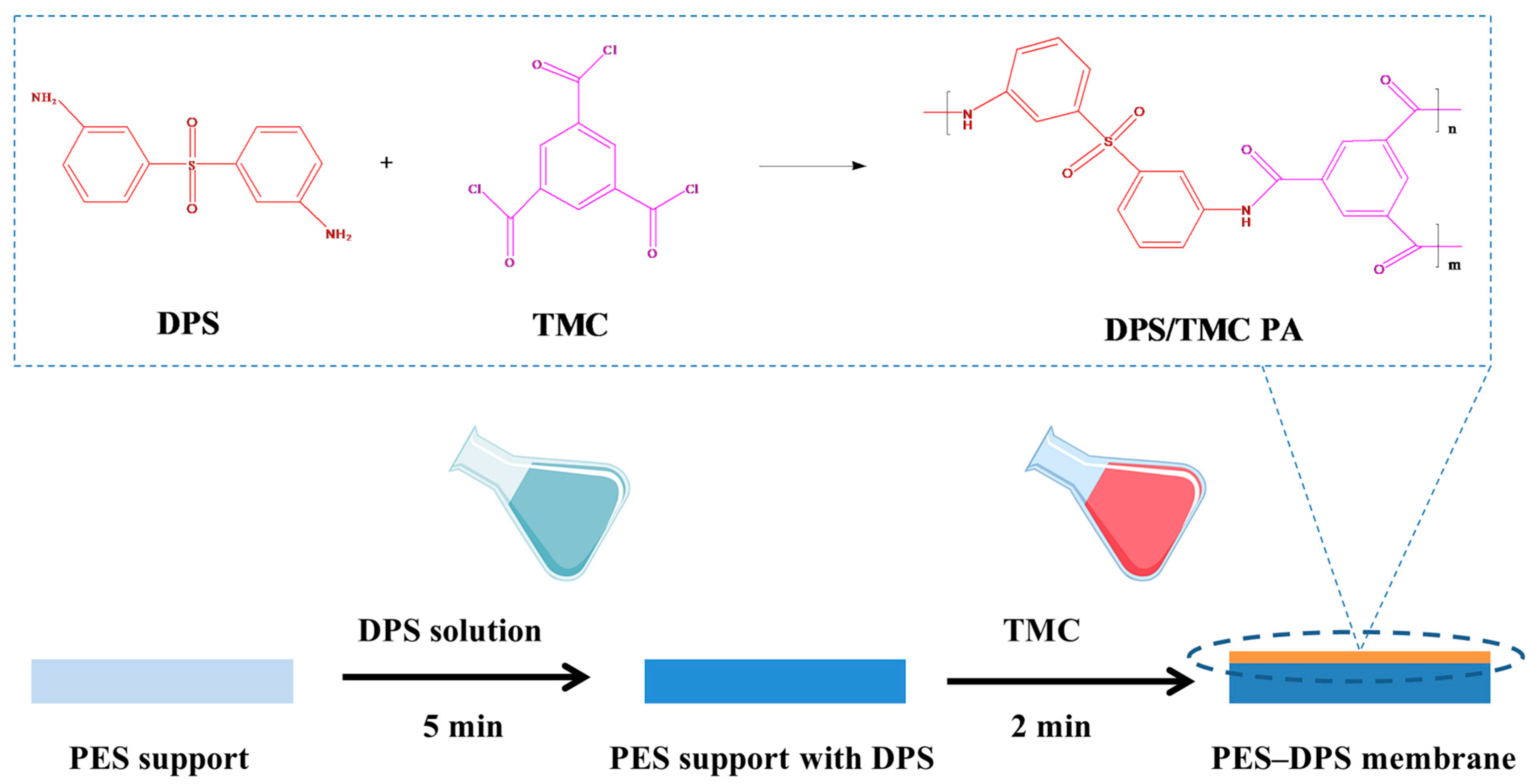
2.2. Fabrication of Loose TFC NF Membranes

The PES substrate was soaked in deionized (DI) water for 12 h before use. Loose TFC NF membranes were fabricated via IP process to form a PA layer on the substrate, as illustrated in Figure 1. A certain amount of DPS was added into 0.2 wt% HCl to form a homogeneous DPS solution (DPS concentration is 0.5, 0.75, 1.0, 2.0, or 3.0 wt%). After immersing the PES substrate into the DPS solution for 5 min, excess solution was cleared away from its surface using a nitrogen gas knife. Then, the PES substrate was brought into contact with a 0.1 w/v% TMC n-hexane solution for 2 min, followed by drying in a fume hood for 5 min. Then the resultant membrane was dried at 60 °C for 10 min. The obtained membrane was rinsed and stored in DI water until use. The loose NF membranes fabricated using different DPS concentrations (0.5, 0.75, 1.0, 2.0, 3.0 wt%) were designated as PES–DPS–0.5, PES–DPS–0.75, PES–DPS–1, PES–DPS–2, and PES–DPS–3, respectively.

2.3. Characterization of Membranes

A Fourier transform infrared spectrometer (FTIR, Nicolet IS50-Nicolet Continuum, Madison, WI, USA) and X-ray photoelectron spectroscopy (XPS, Thermo Scientific K-Alpha, Waltham, MA, USA) were used to analyze the chemical characteristics and composition of the as-prepared membrane surfaces. The morphology of the membranes was inspected by a high-resolution field emission scanning electron microscope (FESEM, Merlin, Oberkochen, Germany). The surface roughness of the membranes was observed using an atomic force microscope (AFM, Multimode 8, Baden-Württemberg, Germany). The charge properties of the membrane surfaces were evaluated using a solid surface zeta potential analyzer (SurPASS, Anton Paar, Graz, Austria). Before characterization, all the above membranes were dried in a vacuum freeze dryer (FD-1B-50, TENLIN, Jiangsu, China) for 12 h.

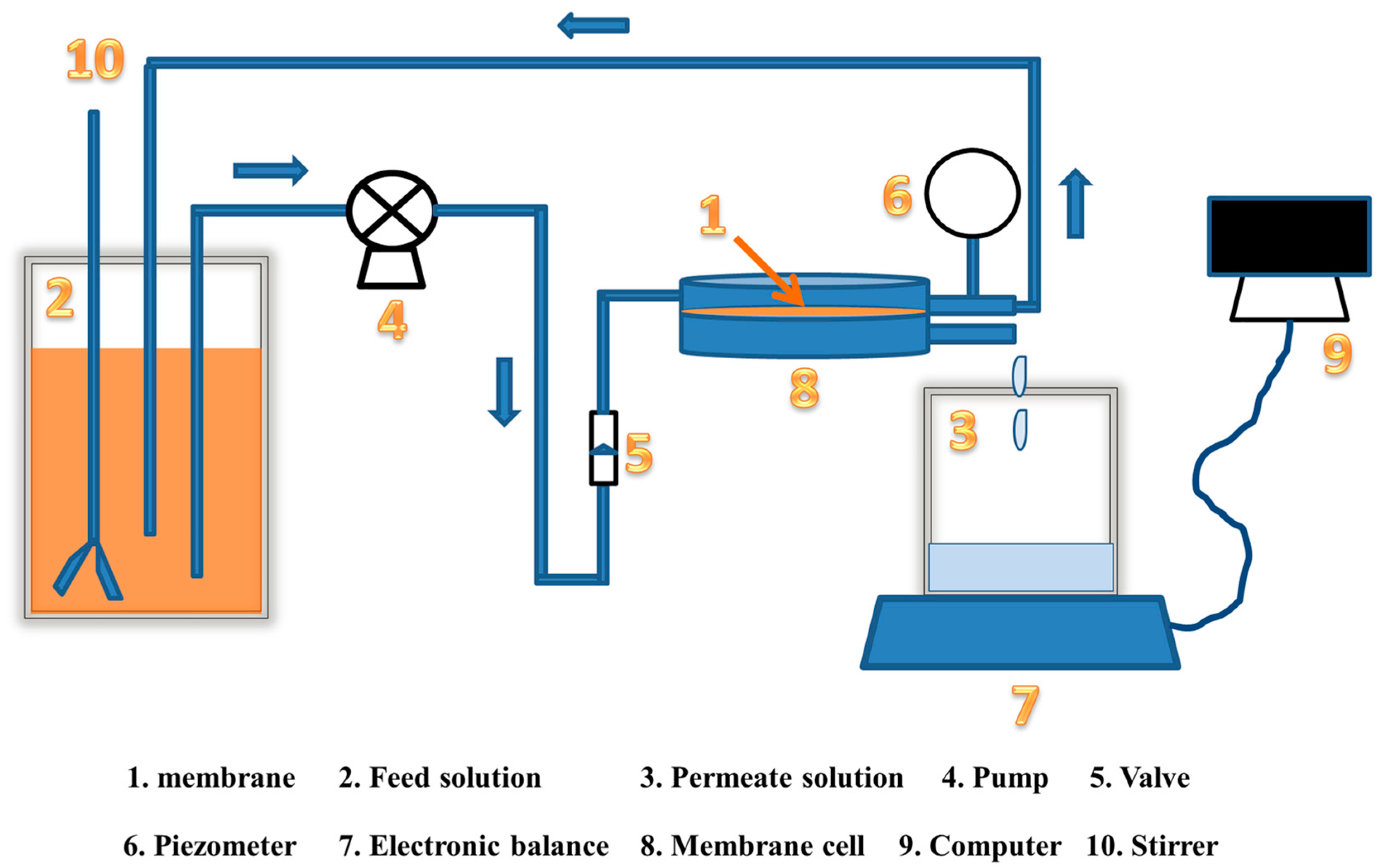
2.4. Filtration Performance of the Membranes

The filtration performance of the prepared loose NF membranes was tested by a crossflow filtration setup with an effective area of 10.17 cm2, as illustrated in Figure 2. Before the performance measurement, membranes were prepressed with DI water at 2 bar for 0.5 h to obtain a steady flux. The filtration performance assessments were tested using 0.2 g·L−1 dye aqueous solutions (CV, CR, G-250, DB71, DR80) or 2 g·L−1 salt solutions (NaCl, MgCl2, MgSO4, Na2SO4). Moreover, dye/salt mixtures containing DB71 (0.05, 0.075, 0.1, 0.2, or 0.3 g·L−1) and Na2SO4 (0.5, 1.0, 2.0, 3.0, or 4.0 g·L−1) were used as the simulated textile wastewater in the dye/salt separation test. The water flux (JW) and the rejection (R) values of the membranes were tested under 2 bar and determined using the following equations:
J w = V A × T × Δ P      
where JW is the water flux (L·m−2·h−1·bar−1), V (L) is the volume of the permeate collected over a duration of T (h), A (m2) is the effective area of the filtration system, and ΔP (bar) is the transmembrane hydraulic pressure.
R = 1 C p C f × 100 %      
where R is the rejection rate to dye or salt (%), Cp and Cf refer to the permeate and feed concentrations, respectively. All performance tests were repeated at least three times to minimize errors in the experimental system.
Molecular weight cut-off (MWCO) of the prepared loose NF membranes was assessed through rejection experiments, utilizing 0.2 g·L−1 PEG solution with different molecular weights (from 200 Da to 1500 Da) at 0.2 MPa. The concentration of PEG solution is measured by total organic carbon analyzer (TOC, Shimadu TOC-L, Tokyo, Japan). The Stokes radius (r) of PEG was calculated according to the following equation:
log r = 1.3363 + 0.395 log ( M w )    
where r is stokers radius and Mw is molecular weight.

2.5. Chlorine Resistance Performance of the Membranes

Chlorine resistance test was performed based on the literature [18]. Specifically, the prepared membranes were submerged in a NaClO solution (pH = 4.0 and active chlorine concentration = 2000 ppm) for specific durations (3, 6, 9, or 12 h). The solution pH was adjusted to 4.0 using HCl to render hypochlorous acid as the active chlorine species [19]. Subsequently, the membranes were rinsed thrice with DI water and tested again to determine their water flux and dye (DB71) rejection performances based on the methods described in Section 2.4. The comparison of the difference in their water flux and dye rejection before and after chlorination was adopted to assess the chlorine resistance performance of the membranes. The total free-chlorine exposure amount (ppm·h) was applied to describe the degree of chlorination of membranes.

3. Results and Discussion

3.1. Membrane Characterization

3.1.1. Morphology of Membranes

Surface morphologies of the prepared membranes were studied via FESEM and AFM tests (Figure 3). Furthermore, a new layer on the TFC membranes covering the pores on the PES membrane surface was observed, which confirms the successful IP process, as seen in Figure 3c–f. Thus, no obvious pores can be seen on the PES–DPS–0.75 to PES–DPS–3 TFC membranes; however, a few pores can be seen on the PES–DPS–0.5 TFC membrane (Figure 3b), possibly because IP process with limited DPS cannot form a sufficiently dense PA layer to completely cover the substrate surface. Meanwhile, more microspherical structures emerged on the membrane surfaces as the DPS concentration increased, mainly due to the accelerated diffusion of DPS as a result of increased concentration [20]. Moreover, microspheres can increase the surface roughness and the filtration area of the obtained membranes, which would be favorable to water transport [21]. Additionally, the surface roughness of membranes was determined via AFM analysis. The AFM results of the prepared membranes are presented in Figure 3a’–f’, which demonstrate that the average roughness (Ra) of the membranes first declined and then mildly increased. The decreased roughness could be explained as a result of massive pores on the substrate surface that were covered with the PA layer. A similar phenomenon was reported in a related research study [8]. Additionally, an increase in the surface roughness may be due to agglomeration of excessive DPS. According to the AFM analysis, all TFC NF membranes surfaces were obviously smoother than the original PES-substrate surface, thus indicating pronounced better antifouling properties of the prepared membranes [22].
Figure 4 shows that the cross-section of the prepared membranes consists of a PA layer and a substrate. The thickness of the PA layer increased from 162 nm for PES to 375 nm for PES–DPS–3 with the increasing DPS concentration. This could be because more DPS penetrated the PES substrate and reacted with TMC as a result of the increased DPS concentration, thus forming a thicker PA layer. Flawless and compact PA layers were observed on the surface of all TFC NF membranes, indicating that the PA structures were tightly adhered to the PES substrates.

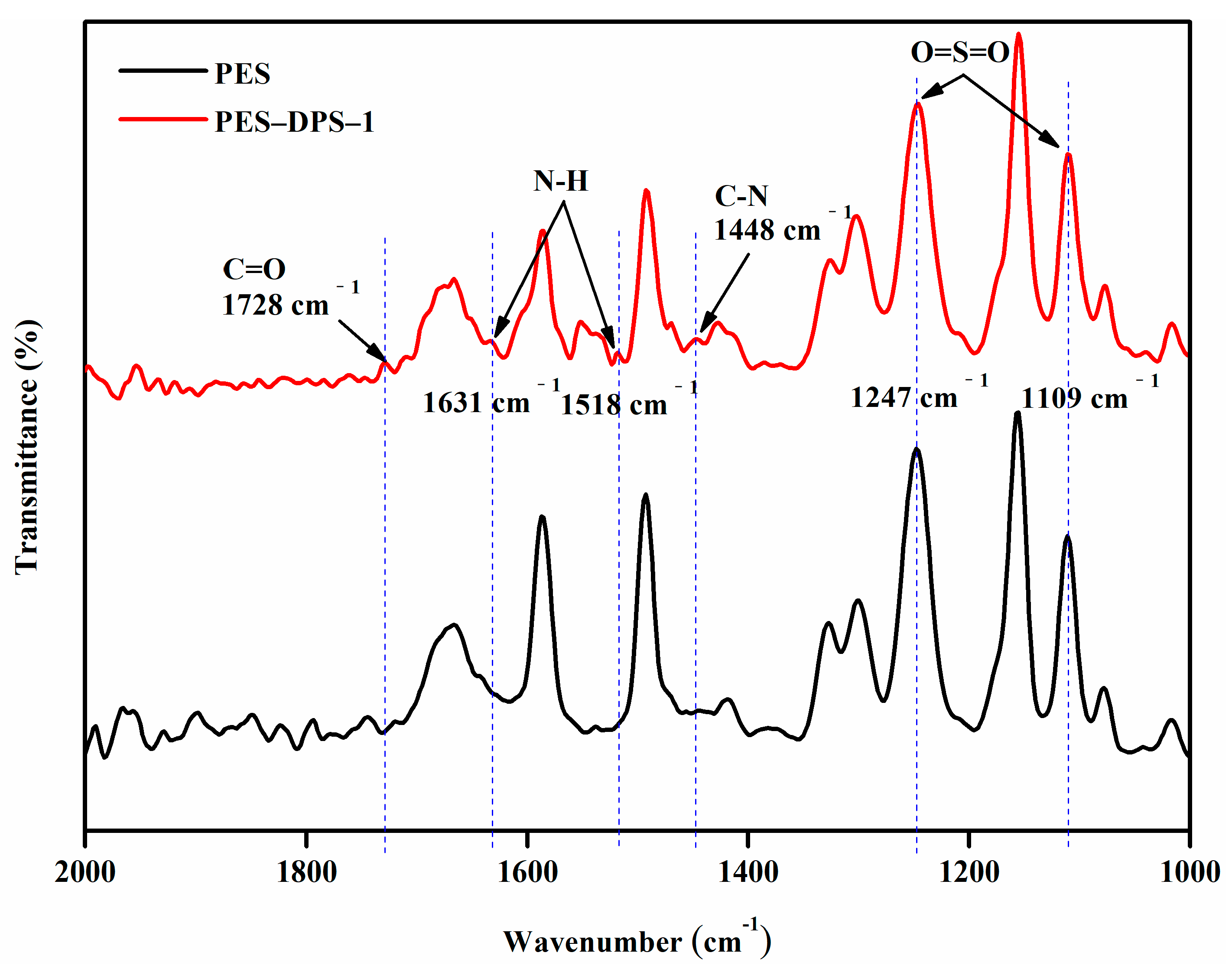
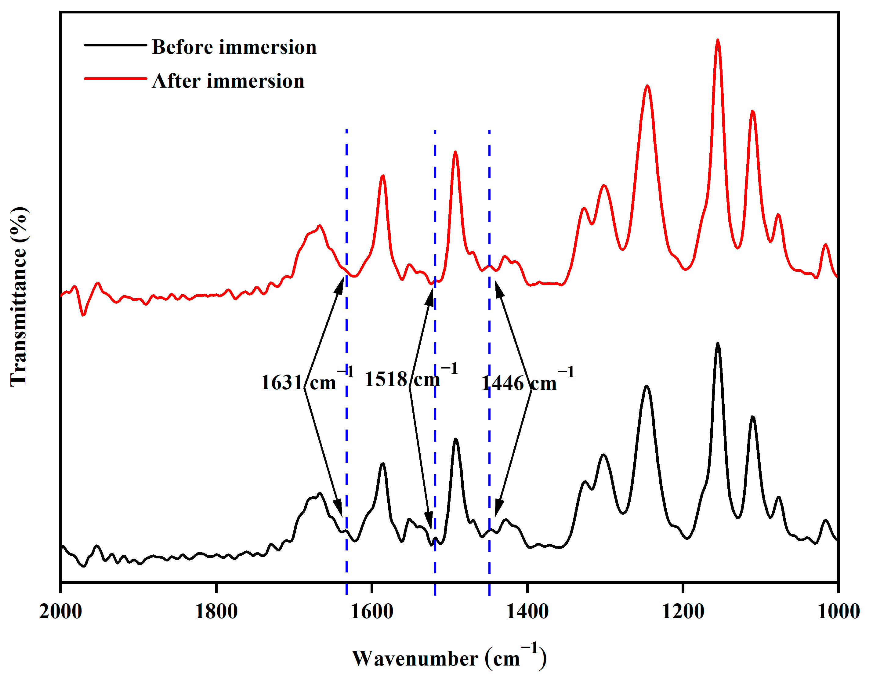
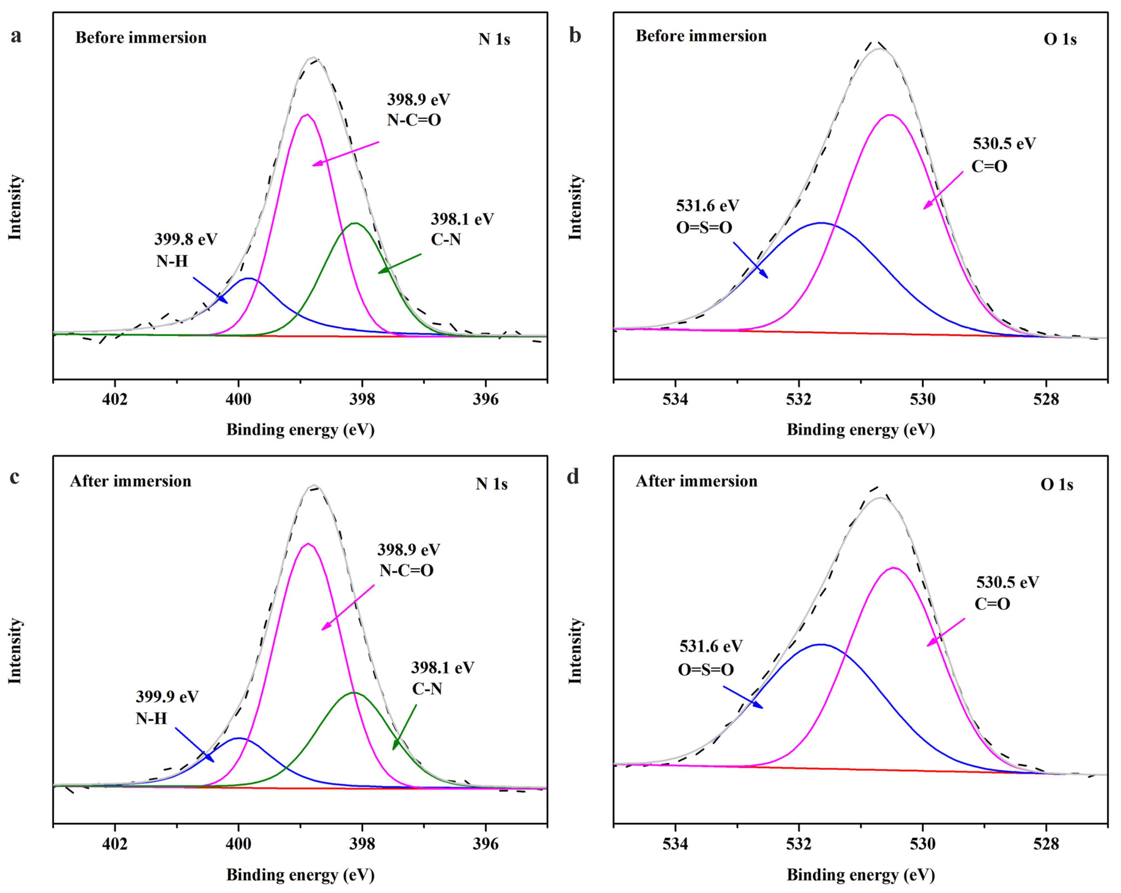
3.1.2. Chemical Composition of the Membranes

FTIR tests of the PES substrate and the PES–DPS–1 membrane were investigated to explore the chemical compositions of the substrate and loose NF membrane. In Figure 5, two obvious absorption peaks can be seen at 1247 cm−1 and 1109 cm−1 from the PES substrate and the PES–DPS–1 membrane, respectively, which could be ascribed to the stretching vibrations of the O=S=O group [23]. Notably, both the PES substrate and the PA layer (derived from DPS) contained O=S=O groups. Different from the PES substrate, new absorption peaks at 1728, 1631, 1518, and 1448 cm−1 corresponding to the C=O bond of the amide groups or –COOH groups, N–H coupling vibration (Amide II), stretching vibration (Amide I), and C–N stretching vibration (Amide III) appeared, verifying the generation of the PA layer via the IP process [24,25].
The elemental composition of the PA layer was obtained via XPS analysis. Figure 6a,b shows the atomic percentage of each element (C, N, O, S) of the PES substrate and PES–DPS–1. Among them, the nitrogen content on PES–DPS–1 surface increased as compared to PES, indicating that the substrate was coated with a PA layer. In addition, the PES–DPS–1 membrane showed a lower S/O ratio than the pristine PES substrate. In fact, S/O ratio decreased with the increasing oxygen atoms on the membrane surfaces, which further confirmed the successful synthesis of the PA layer. Moreover, the high-resolution C1s spectra of PES and PES–DPS–1 were shown in Figure 6c,d. The C1s spectra of PES substrate could be resolved to two deconvolution peaks: a major peak is at 284.1 eV corresponding to C–C bonds and a second peak at 285.6 eV assigned to C–O or C–S or C–N. However, a new deconvolution peak at 287.1 eV was found in the C1s spectra of the PES–DPS–1 membrane suggesting the existence of N–C=O [9], which originated from the amide groups of the PA layer. These results again confirmed the presence of an active PA layer on the membrane surface.

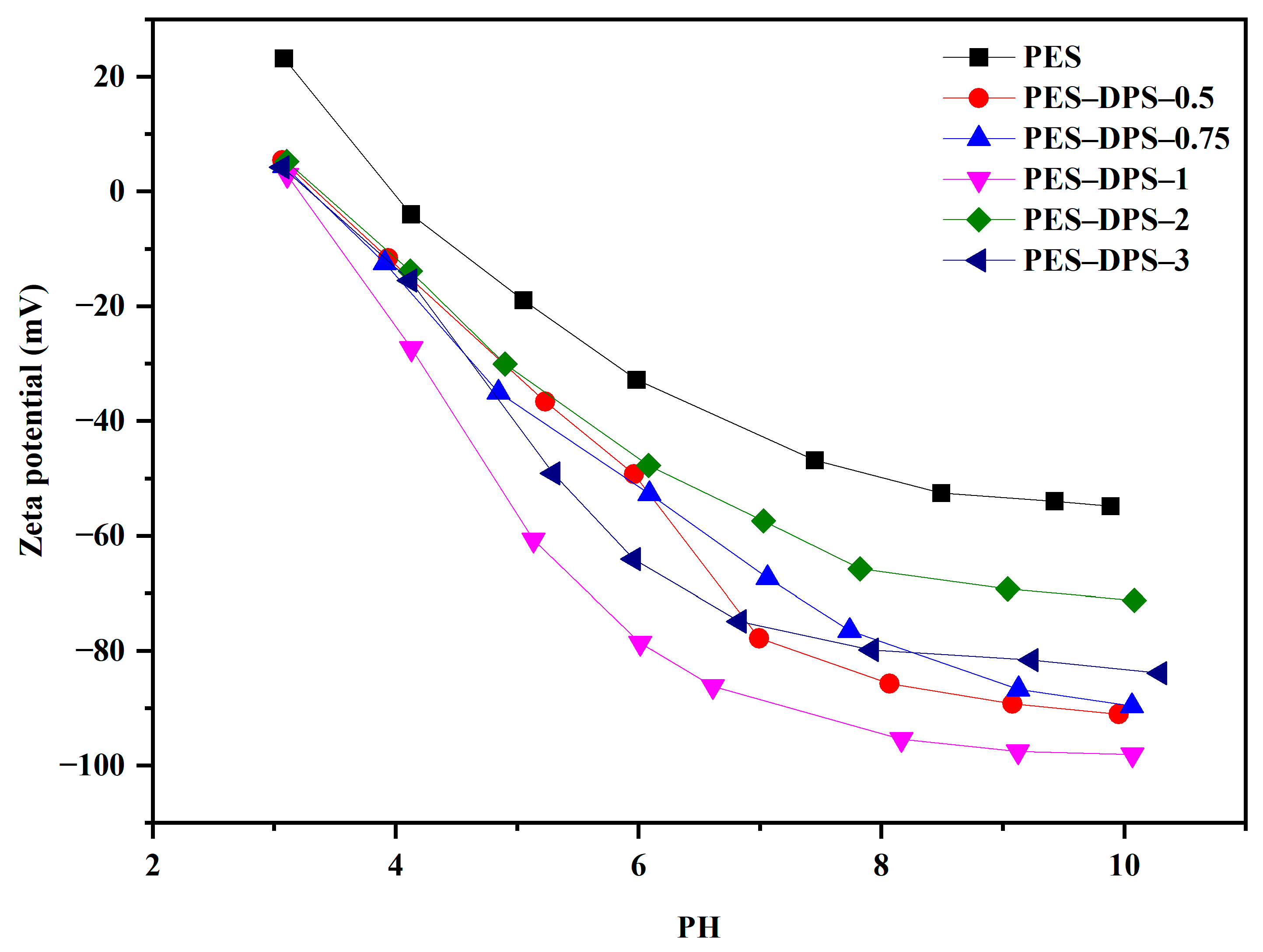
3.1.3. Surface Charge of Membranes

The surface zeta potentials of loose TFC NF membranes and the pristine PES membrane were measured in the pH range of 3–10 to evaluate the surface charge. As shown in Figure 7, all membranes were negatively charged for the pH range of 4–10. Moreover, all loose TFC NF membranes consistently carried more negative charges than pristine PES, which was attributed to the hydrolysis of more acyl chlorides in the PA layer [24]. Notably, more negative charges on the membrane surface will contribute to a more optimal separation of negatively charged dyes.

3.2. Membrane Separation Performance

3.2.1. Pure Water Flux of the Membranes

Pure water flux (PWF) is a key parameter that directly reflects the transfer ability of membranes [26]. The PWF values of pristine PES and loose TFC NF membranes are presented in Figure 8, wherein the PWF of the PES membrane was 105.1 L·m−2·h−1·bar−1, which dramatically decreased to 10.4 L·m−2·h−1·bar−1 after the IP process on the PES substrate when the DPS concentration increased to 3 wt%. This is mainly due to the fact that the PES membrane was covered with an active layer in the IP process, which may have markedly reduced the number of water channels on the surface. Notably, the PES–DPS–1 membrane showed a relatively high flux (49.4 L·m−2·h−1·bar−1).

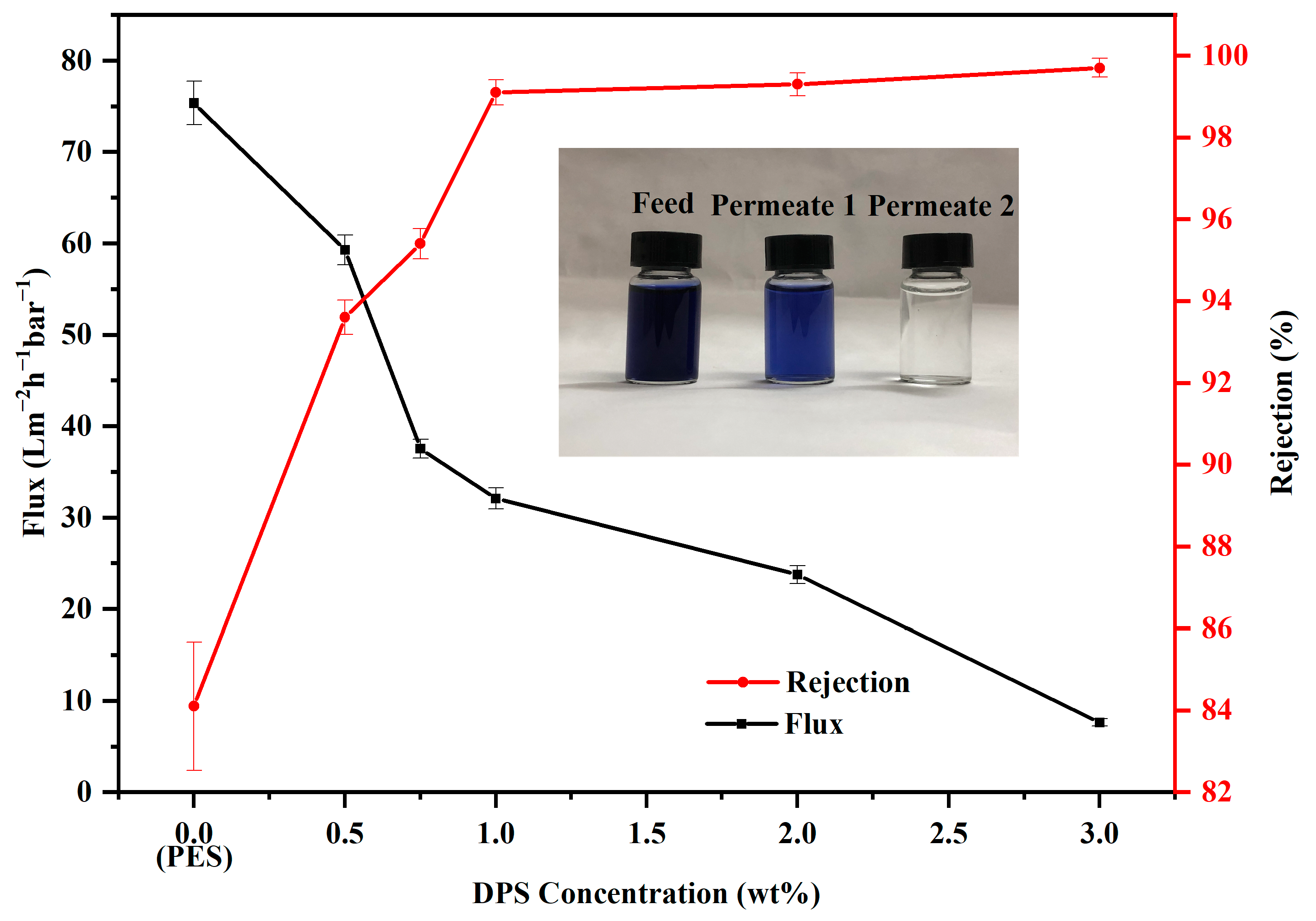
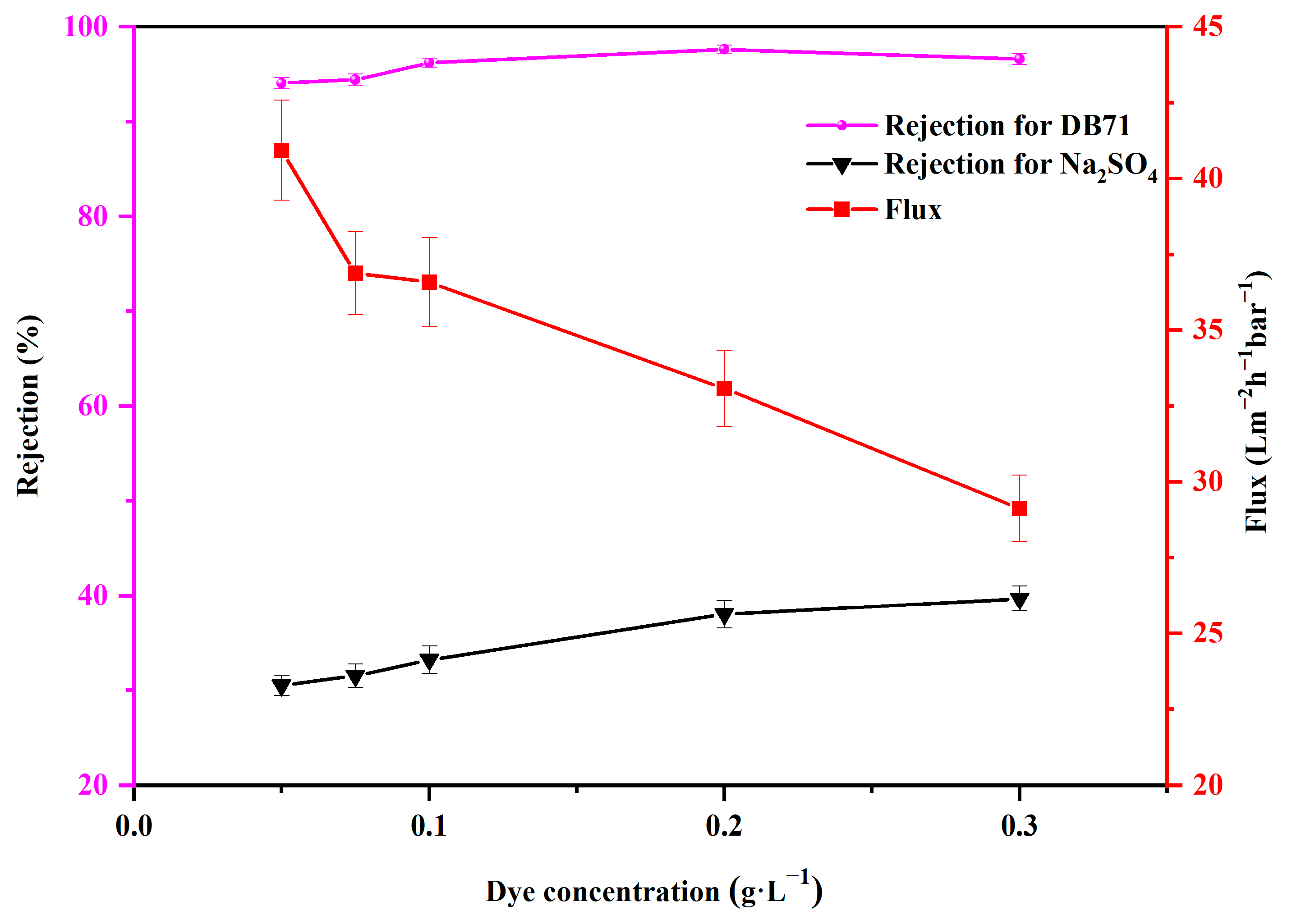
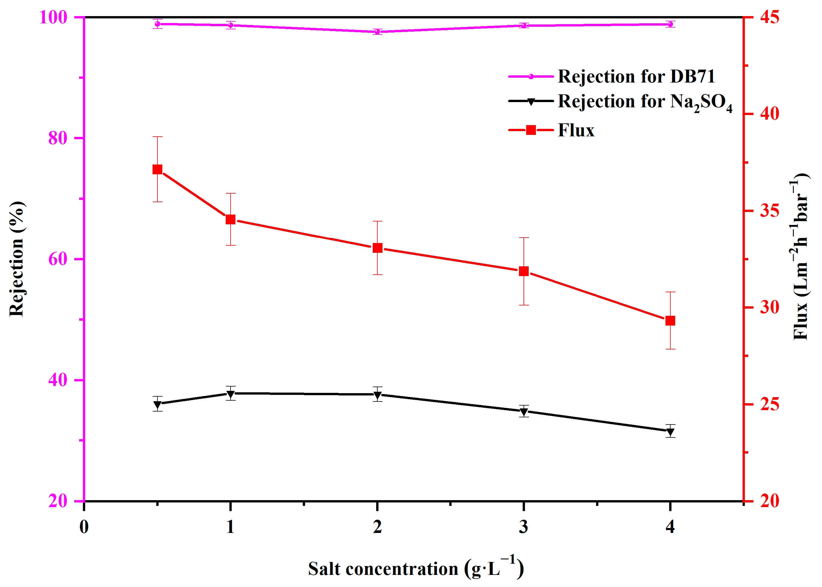
3.2.2. Optimization of the Separation Performance

Membrane separation performance was investigated via filtration of DB71 aqueous solutions. The effect of DPS concentrations on the separation performance of the prepared membranes is displayed in Figure 9. As we can see, the water flux and the DB71 rejection by the support membrane (PES) were 75.34 L·m−2·h−1·bar−1 and 84.1%. When the concentration of DPS increased from 0.5 wt% to 3.0 wt%, it can be seen the water flux decreased significantly from 59.27 L·m−2·h−1·bar−1 to 7.64 L·m−2·h−1·bar−1, whereas DB71 rejection increased from 93.6% to 99.7%. The decline in flux was primarily attributed to the fact that when the concentration of DPS increased, it was easier to form thicker and more compact separation layers through the IP process, thus increasing the mass transfer resistance of the membranes. Membranes with low DPS concentrations exhibited high water flux and low DB71 rejection. A low DPS concentration did not provide enough amine groups for the IP process, thus forming a relatively loose and thin separation layer on the membrane surface. When the DPS concentration was further increased, fewer water channels and a thicker separation layer noticeably decreased the water flux and increased the DB71 rejection. For optimal water flux and dye rejection, the most suitable DPS concentration was 1.0 wt%. Therefore, PES–DPS–1 membrane was used for further explorations in this study.

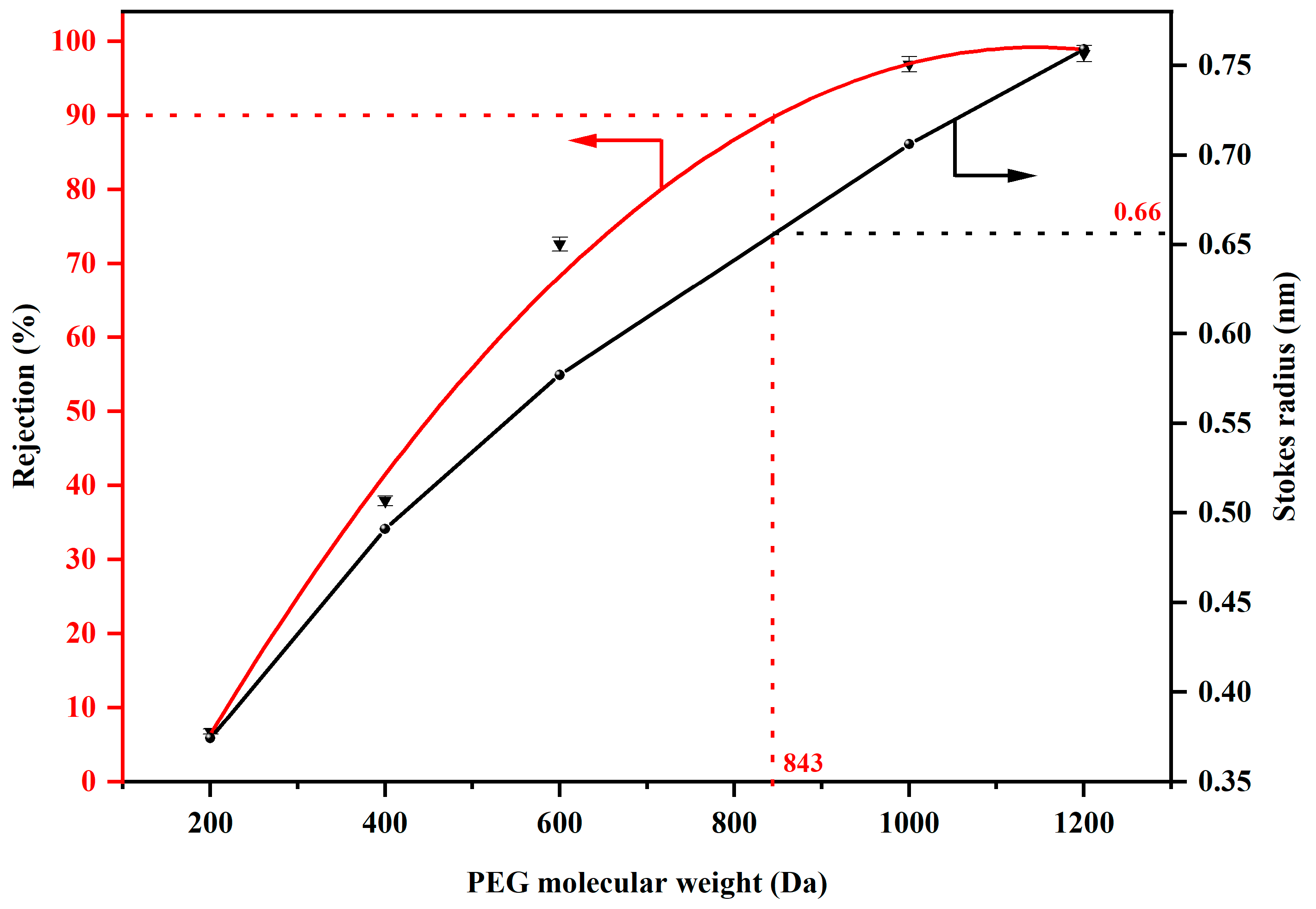
3.2.3. MWCO of the PES–DPS–1 Membrane

We employed various molecular weights of PEG to conduct size characterization of the membrane, and the results were displayed in Figure 10. As we can see, the PES–DPS–1 membrane exhibited a low MWCO of 843 Da and it corresponds to a pore size of 1.32 nm (Equation (3) of Section 2.3).

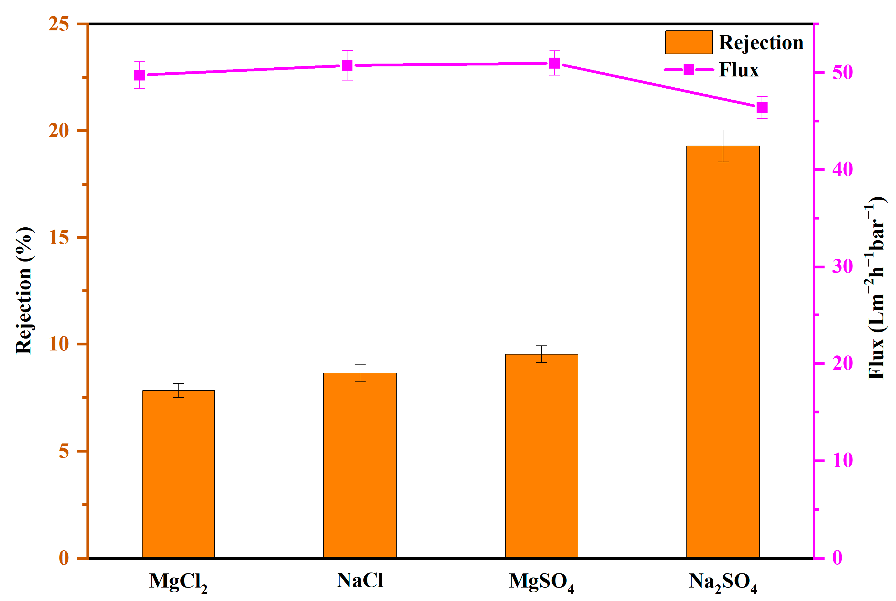
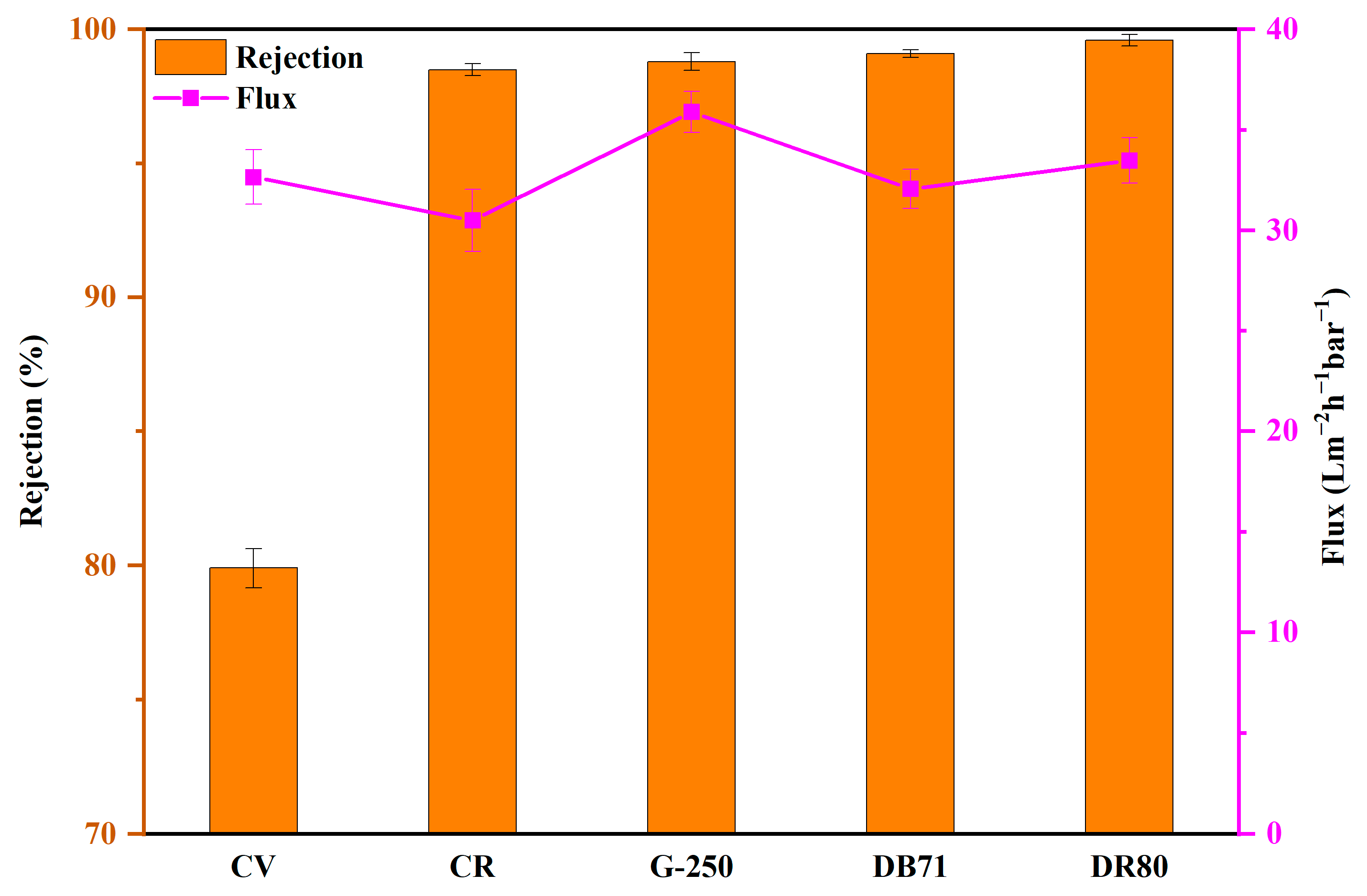
3.2.4. Solute Rejection by the PES–DPS–1 Membrane

The performance of solute rejection was evaluated by using four common salts: NaCl, MgCl2, MgSO4, Na2SO4 and six types of dyes: CV, CR, G-250, DB71, and DR80. More detailed information about these dyes is provided in Table 1. As illustrated in Figure 11, the rejection rates for inorganic salts by the membrane were as follows: Na2SO4 (19.3%), MgSO4 (9.5%), NaCl (8.7%), and MgCl2 (7.8%). The electrostatic repulsion between the negative membrane surface and SO42− (divalent anions) was stronger than that with Cl (monovalent anions), leading to a higher rejection of sulfates than chlorides [23,27]. Additionally, Mg2+ experienced a lower rejection compared with Na+, possibly due to their greater affinity towards the negatively charged surface of the membrane, which enables them to pass through more readily. The following are the hydration radii of the four ions: Cl (0.33 nm), Na+ (0.36 nm), SO42− (0.38 nm), and Mg2+ (0.43 nm) [28]. Another reason why the membrane exhibited low inorganic salt rejections is because the average pore size (1.32 nm) of the membrane is much larger than the hydration radius of all four ions mentioned above. It is also worth noting that the low salt rejection may be attributed to the presence of defects in the polyamide membrane, which could have been caused by the rapid quenching of the reaction during interfacial polymerization, particularly with the emergence of additional acid. Moreover, the water flux values of PES–DPS–1 for MgCl2, NaCl, MgSO4, and Na2SO4 were 49.7, 50.7, 50.9, and 46.4 L·m−2·h−1·bar−1, respectively. Consequently, PES–DPS–1 membrane exhibited low inorganic salt rejections for different salts and a relatively higher water flux owing to the negatively charged surface and a relatively loose membrane structure.
In addition, the removal rate and the water flux of the PES–DPS–1 membrane for the tested dyes with different molecular weights are shown in Figure 12. PES–DPS–1 membrane exhibited high rejections toward CR (98.5%), G-250 (98.8%), DB71 (99.1%), and DR80 (99.6%), with relatively low rejection toward CV (79.9%). The negative dye molecules (CR, G-250, DB71, and DR80) were repelled by the negatively charged PES–DPS–1 membrane surface. In contrary, the negatively charged PES-DPS-1 surface exhibits a powerful electrostatic adsorption effect on positively charged CV molecules, thereby diminishing the negative charge density present on the surface of the membrane. Therefore, the rejection of CR, G-250, DB71, and DR80 was higher than CV. Interestingly, both CR (696.66) and G-250 (825.97) dyes have molecular weights smaller than the MWCO (843) of the PES-DPS membrane; nevertheless, the membrane rejected both dyes with high efficiency. However, previous research has indicated that dyes with ring structures do not exist as individual dye molecules in a solution, but instead have a tendency to aggregate and form larger molecular clusters [29]. Therefore, pore-size characterization by dye molecules weight may not be accurate and cannot present the actual rejection behavior. Compared with PWF (46.4 L·m−2·h−1·bar−1), water flux slightly decreased to 30.5, 35.9, 32.1, 33.5, and 32.7 L·m−2·h−1·bar−1 for CR, G-250, DB71, DR80 and CV, respectively. This was primarily ascribed to the increased permeation resistance due to the dye molecule deposition on the membrane surface and pore blockage. In short, PES–DPS–1 exhibited a relatively low salt rejection (<20%) and a high dye-removal efficiency (>98%), indicating a good separation performance for dyes and salts.

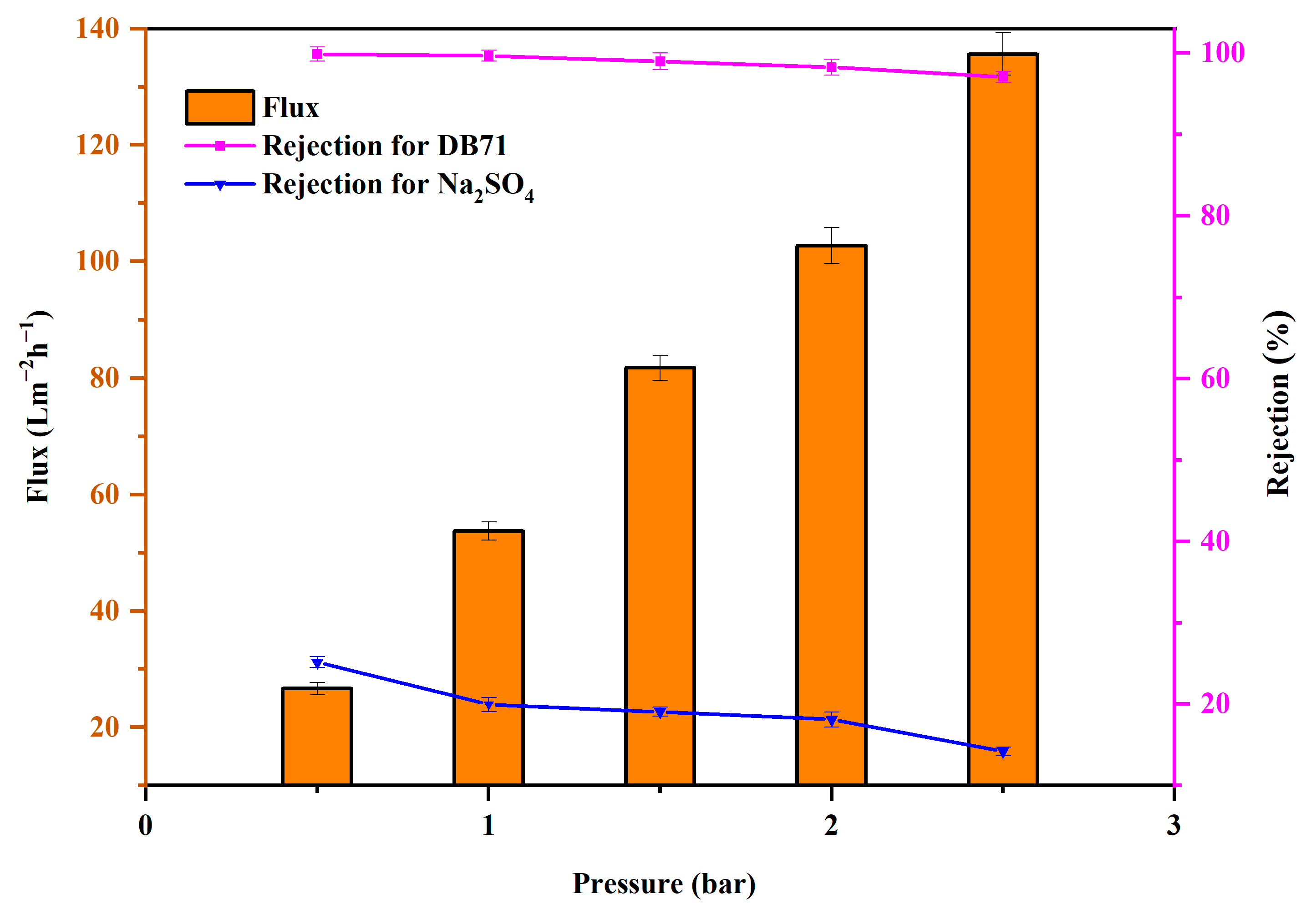
3.2.5. Effect of Operating Pressure on the Separation Performance

To further explore the properties of the PES–DPS–1 membrane, the influence of the operating pressure on the membrane’s dye/salt separation performance was studied. Figure 13 shows the PWF and solute rejection by PES–DPS–1 at 0.5, 1.0, 1.5, 2.0, 2.5 bar. With an increase in the operating pressure from 0.5 to 2.5 bar, the rejection of DB71 and Na2SO4 decreased from 99.8% to 97.1% and from 25.2% to 14.2%, respectively. These experimental results are consistent with those in previous studies [30,31,32]. The decline in the solute rejection may be attributed to the increase of operating pressure, allowing for an easier passage of a dye or a salt. Meanwhile, the membrane’s PWF regularly increased from 26.6 L·m−2·h−1 to 135.6 L·m−2·h−1 as the test pressure increased, and it confirmed the formation of a stable separation layer on the PES substrate. The PES–DPS–1 membrane displayed good permeability even at a low operating pressure, thus saving energy [33].
In loose NF, the transmembrane pressure can be relatively low compared to other types of membranes because of several factors: (i) loose NF membranes have larger pore sizes compared to conventional NF membranes. This means that the membranes are less restrictive, and the flow of liquid through the membrane is easier; and (ii) loose NF membranes have lower resistance to the flow of liquid than tight NF membranes. This is because the pores in loose membranes are larger, and the membrane structures are more flexible.

3.2.6. Dye Desalination Performance of PES–DPS–1 Membrane

Meanwhile, the separation performance of PES–DPS–1 was studied at different dye (DB71) and salt (Na2SO4) concentrations. Figure 14 displays the effect of dye (DB71) concentrations on the desalination efficiency of the PES–DPS–1. The rejections of DB71 and Na2SO4 slightly increased by increasing the DB71 concentration, while the water flux decreased from 40.9 L·m−2·h−1·bar−1 to 29.1 L·m−2·h−1·bar−1. This could be explained by the deposition of dyes on the membrane surface and the blockage of the pores. Based on previous relevant articles, this could also be due to dye aggregation as well as concentration polarization [34].
Figure 15 displays the effect of salt (Na2SO4) concentration on dye desalination performance of PES–DPS–1, wherein DB71 rejection slightly decreased from 98.9% to 98.7% when the Na2SO4 content was increased from 0.5 g·L−1 to 4.0 g·L−1, indicating that the increase in the Na2SO4 concentration showed no obvious effect on the separation performance of the membrane, a trend consistent with other literature studies [24]. Additionally, the water flux decreased from 37.2 L·m−2·h−1·bar−1 to 29.3 L·m−2·h−1·bar−1, as induced by the concentration polarization of Na2SO4. The rejection of Na2SO4 slightly declined (from 36.1% to 31.6%) with the increasing Na2SO4 concentration, possibly because high Na2SO4 concentrations could facilitate the electrostatic shield effect [35,36,37]. Thus, we inferred that PES–DPS–1 demonstrated a good separation performance despite high DB71 or Na2SO4 concentrations. The relatively low reactivity of the DPS molecules contributed to the formation of a loose PA separation layer, which enhanced the water flux and dye desalination performance of the membrane. This proved the potential of the PES–DPS–1 membrane in dye desalination.

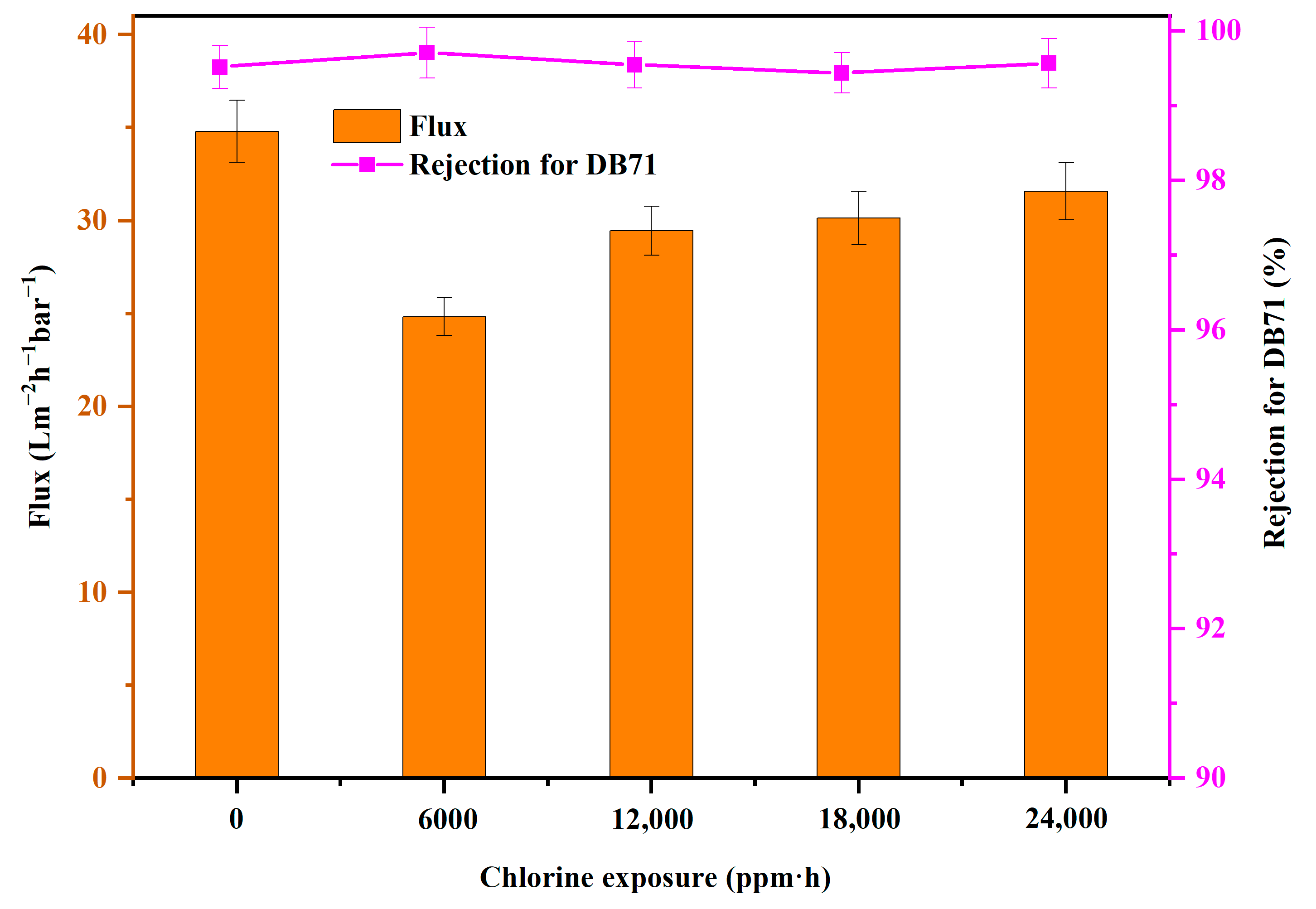
3.3. Membrane Chlorine Resistance Evaluations

Chlorine-resistance performance is a significant evaluation index for PA membranes, since the NaClO solution is universally used for cleaning membrane fouling [38,39]. Chlorine resistance by composite NF membranes is directly related to their lifetime [40]. The dye rejection ability and water flux of PES–DPS–1 at different chlorine exposure amounts are exhibited in Figure 16, wherein the water flux of the PES–DPS–1 membrane decreased at the 6000-ppm·h chlorine exposure amount. This phenomenon was attributed to the conversion of the N–H groups into N–Cl by partial chlorination, thus forming a more compact membrane [41]. Nevertheless, the water flux of the membrane was relatively stable after 12,000-ppm·h chlorine exposure, which was consistent with the previous literature [42]. Notably, the dye rejection did not change significantly before and after chlorine immersion. This demonstrated that the PES–DPS–1 membrane possessed excellent chlorine resistance.
Furthermore, the FTIR analysis of PES–DPS–1 after its immersion in chlorine was performed to determine the stability of the PA layer. As shown in Figure 17, the absorption peaks at 1631 cm−1, 1518 cm−1, and 1446 cm−1 corresponding to the amide bond of the PA layer on the PES–DPS–1 membrane surface were still present after the membrane immersion in chlorine. The N 1s and O 1s high-resolution spectra of PES–DPS–1 (Figure 18) barely changed after membrane immersion in chlorine. These results indicate the maintained stability of the amide-rejection layer. The excellent chlorine resistance by the PES–DPS–1 membrane could be explained by the strong electron-withdrawing effect of the O=S=O groups of DPS. The introduction of O=S=O groups as the protective groups can significantly reduce the density of electron clouds and make the aromatic ring less reactive, thus inhibiting the conversion of N–H groups into N–Cl and Orton rearrangement [43,44].

4. Conclusions

In this study, novel loose NF membranes with outstanding chlorine stability and high dye/salt separation efficiency were fabricated via IP technology. The optimal membrane, PES–DPS–1 exhibited high rejections toward CR (98.5%), G-250 (98.8%), DB71 (99.1%), and DR80 (99.6%) dyes and low inorganic salt rejections (Na2SO4 19.3%, MgSO4 9.5%, NaCl 8.7%, MgCl2 7.8%). Meanwhile, the PES–DPS–1 membrane displayed a relatively high PWF (49.4 L·m−2·h−1·bar−1) even at a low-operating pressure (2 bar). Specifically, the membrane showed outstanding chlorine stability, and the strong electron-withdrawing effect of the O=S=O groups of DPS contributed to the formation of a PA layer with excellent chlorine resistance. No significant changes in the dye rejection performance of PES–DPS–1 were observed post immersion in NaClO solution (pH = 4.0, 2000 ppm) for 12 h. Based on such promising results, the current work provides a novel approach to develop loose NF membranes with an outstanding chlorine stability and a high dye/salt selectivity.

Author Contributions

Conceptualization, S.Z. and K.Z.; methodology, K.Z. and L.H.; validation, Y.J.; formal analysis, L.H.; inverstigation, L.H.; resources, L.H.; data curation, Y.J.; writing-original draft preparation, L.H.; writing-review and editing, L.H.; visualization, Y.J.; supervision, K.Z.; project administration, S.Z.; funding acquisition, S.Z. All authors have read and agreed to the published version of the manuscript.

Funding

This research was funded by Guangdong Basic and Applied Basic Research Foundation, grant number 2021A1515110369 and the Ministry of Science and Technology of China for State Key Research and Development Project, grant number 2022YFC3705003.

Data Availability Statement

The data that support the findings of this study are available from the corresponding author upon reasonable request.

Conflicts of Interest

The authors declare that they have no known competing financial interests or personal relationships that could have appeared to influence the work reported in this paper.

Abbreviations

NFnanofiltration
DPS3,3′-diaminodiphenyl sulfone
IPinterfacial polymerization
POPsporous organic polymers
TMCtrimesoyl chloride
APS2-aminophenol-4-sulfonic
PESpolyethersulfone
DIdeionized
FTIRfourier transform infrared spectrometer
FESEMfield emission scanning electron microscope
Raaverage roughness
PEGpolyethylene glycol
PA–TFCpolyamide thin-film composite
PApolyamide
CVcrystal violet
CRcongo red
G-250coomassie brilliant blue G-250
DB71direct blue 71
DR80direct red 80
TFCthin-film composite
XPSX-ray photoelectron spectroscopy
AFMatomic force microscope
PWFpure water flux
MWCOmolecular weight cut-off

References

  1. Naeim, S.; Emam, A.A.; Mobarak, M.F.; Hosny, R. Textile water treatment via adsorption of basic brown 1 dye on ZnO/PVC nanocomposite membrane through membrane adsorption process. Desalination Water Treat. 2021, 227, 58–67. [Google Scholar] [CrossRef]
  2. Mubarak, M.F.; Ragab, A.H.; Hosny, R.; Ahmed, I.A.; Ahmed, H.A.; El-Bahy, S.M.; El Shahawy, A. Enhanced Performance of Chitosan via a Novel Quaternary Magnetic Nanocomposite Chitosan/Grafted Halloysitenanotubes@ZnγFe3O4 for Uptake of Cr (III), Fe (III), and Mn (II) from Wastewater. Polymers 2021, 13, 2714. [Google Scholar] [CrossRef] [PubMed]
  3. El-Saeed, R.A.; Hosny, R.; Mubarak, M.F.; Abdou, M.M.; Shoueir, K.R. An innovative SiO2-pyrazole nanocomposite for Zn(II) and Cr(III) ions effective adsorption and anti-sulfate-reducing bacteria from the produced oilfield water. Arab. J. Chem. 2022, 15, 103949. [Google Scholar] [CrossRef]
  4. Li, C.; Wang, H.; Lu, D.; Wu, W.; Ding, J.; Zhao, X.; Xiong, R.; Yang, M.; Wu, P.; Chen, F.; et al. Visible-light-driven water splitting from dyeing wastewater using Pt surface-dispersed TiO2-based nanosheets. J. Alloys Compd. 2017, 699, 183–192. [Google Scholar] [CrossRef]
  5. Tavangar, T.; Karimi, M.; Rezakazemi, M.; Reddy, K.R.; Aminabhavi, T.M. Textile waste, dyes/inorganic salts separation of cerium oxide-loaded loose nanofiltration polyethersulfone membranes. Chem. Eng. J. 2020, 385, 123787. [Google Scholar] [CrossRef]
  6. Liu, S.; Wang, Z.; Song, P. Free Radical Graft Copolymerization Strategy To Prepare Catechin-Modified Chitosan Loose Nanofiltration (NF) Membrane for Dye Desalination. ACS Sustain. Chem. Eng. 2018, 6, 4253–4263. [Google Scholar] [CrossRef]
  7. Safarpour, M.; Vatanpour, V.; Khataee, A. Preparation and characterization of graphene oxide/TiO2 blended PES nanofiltration membrane with improved antifouling and separation performance. Desalination 2016, 393, 65–78. [Google Scholar] [CrossRef]
  8. Li, R.; Mai, Z.; Peng, D.; Xu, S.; Wang, J.; Zhu, J.; Zhang, Y. In situ formation of porous organic polymer-based thin polyester membranes for loose nanofiltration. J. Membr. Sci. 2022, 644, 120074. [Google Scholar] [CrossRef]
  9. Liu, L.; Zuo, X.; He, J.; Zhou, Y.; Xiong, J.; Ma, C.; Chen, Z.; Yu, S. Fabrication and characterization of 2-aminophenol-4-sulfonic acid-integrated polyamide loose nanofiltration membrane. J. Membr. Sci. 2021, 640, 119867. [Google Scholar] [CrossRef]
  10. Xu, M.; Feng, X.; Liu, Z.; Han, X.; Zhu, J.; Wang, J.; Van der Bruggen, B.; Zhang, Y. MOF laminates functionalized polyamide self-cleaning membrane for advanced loose nanofiltration. Sep. Purif. Technol. 2021, 275, 119150. [Google Scholar] [CrossRef]
  11. Zheng, J.; Zhao, R.; Uliana, A.A.; Liu, Y.; de Donnea, D.; Zhang, X.; Xu, D.; Gao, Q.; Jin, P.; Liu, Y.; et al. Separation of textile wastewater using a highly permeable resveratrol-based loose nanofiltration membrane with excellent anti-fouling performance. Chem. Eng. J. 2022, 434, 134705. [Google Scholar] [CrossRef]
  12. Glater, J.; Zachariah, M.R. A Mechanistic Study of Halogen Interaction with Polyamide Reverse-Osmosis Membranes. In Reverse Osmosis and Ultrafiltration; ACS Symposium Series; ACS Publications: Washington, DC, USA, 1985; pp. 345–358. [Google Scholar]
  13. Kim, Y.K.; Lee, S.Y.; Kim, D.H.; Lee, B.S.; Nam, S.Y.; Rhim, J.W. Preparation and characterization of thermally crosslinked chlorine resistant thin film composite polyamide membranes for reverse osmosis. Desalination 2010, 250, 865–867. [Google Scholar] [CrossRef]
  14. Kang, G.-D.; Gao, C.-J.; Chen, W.-D.; Jie, X.-M.; Cao, Y.-M.; Yuan, Q. Study on hypochlorite degradation of aromatic polyamide reverse osmosis membrane. J. Membr. Sci. 2007, 300, 165–171. [Google Scholar] [CrossRef]
  15. Liu, M.; Chen, Q.; Wang, L.; Yu, S.; Gao, C. Improving fouling resistance and chlorine stability of aromatic polyamide thin-film composite RO membrane by surface grafting of polyvinyl alcohol (PVA). Desalination 2015, 367, 11–20. [Google Scholar] [CrossRef]
  16. Xue, J.; Jiao, Z.; Bi, R.; Zhang, R.; You, X.; Wang, F.; Zhou, L.; Su, Y.; Jiang, Z. Chlorine-resistant polyester thin film composite nanofiltration membranes prepared with β-cyclodextrin. J. Membr. Sci. 2019, 584, 282–289. [Google Scholar] [CrossRef]
  17. Kim, S.H.; Kwak, S.-Y.; Suzuki, T. Positron Annihilation Spectroscopic Evidence to Demonstrate the Flux-Enhancement Mechanism in Morphology-Controlled Thin-Film-Composite (TFC) Membrane. Environ. Sci. Technol. 2005, 39, 1764–1770. [Google Scholar] [CrossRef]
  18. Wu, B.; Weng, X.-D.; Wang, N.; Yin, M.-J.; Zhang, L.; An, Q.-F. Chlorine-resistant positively charged polyamide nanofiltration membranes for heavy metal ions removal. Sep. Purif. Technol. 2021, 275, 119264. [Google Scholar] [CrossRef]
  19. Lounder, S.J.; Asatekin, A. Fouling- and Chlorine-Resistant Nanofiltration Membranes Fabricated from Charged Zwitterionic Amphiphilic Copolymers. ACS Appl. Polym. Mater. 2022, 4, 7998–8008. [Google Scholar] [CrossRef]
  20. Jin, P.; Chergaoui, S.; Zheng, J.; Volodine, A.; Zhang, X.; Liu, Z.; Luis, P.; Van der Bruggen, B. Low-pressure highly permeable polyester loose nanofiltration membranes tailored by natural carbohydrates for effective dye/salt fractionation. J. Hazard. Mater. 2022, 421, 126716. [Google Scholar] [CrossRef]
  21. Tan, Z.; Chen, S.; Peng, X.; Zhang, L.; Gao, C. Polyamide membranes with nanoscale Turing structures for water purification. Science 2018, 360, 518–521. [Google Scholar] [CrossRef] [Green Version]
  22. Al-Mhyawi, S.R.; Mubarak, M.F.; Hosny, R.; Amine, M.; Abdelraheem, O.H.; Zayed, M.A.; Ragab, A.H.; El Shahawy, A. Enhanced Nanofiltration Process of Thin Film Composite Membrane Using Dodecyl Phenol Ethoxylate and Oleic Acid Ethoxylate for Oilfield Calcite Scale Control. Membranes 2021, 11, 855. [Google Scholar] [CrossRef]
  23. Mi, Y.F.; Wang, N.; Qi, Q.; Yu, B.; Peng, X.D.; Cao, Z.H. A loose polyamide nanofiltration membrane prepared by polyether amine interfacial polymerization for dye desalination. Sep. Purif. Technol. 2020, 248, 117079. [Google Scholar] [CrossRef]
  24. Feng, X.; Liu, D.; Ye, H.; Peng, D.; Wang, J.; Han, S.; Zhang, Y. High-flux polyamide membrane with improved chlorine resistance for efficient dye/salt separation based on a new N-rich amine monomer. Sep. Purif. Technol. 2021, 278, 119533. [Google Scholar] [CrossRef]
  25. Fathy, M.; Hosny, R.; Keshawy, M.; Gaffer, A. Green synthesis of graphene oxide from oil palm leaves as novel adsorbent for removal of Cu(II) ions from synthetic wastewater. Graphene Technol. 2019, 4, 33–40. [Google Scholar] [CrossRef]
  26. Mahmoudian, M.; Kochameshki, M.G. The performance of polyethersulfone nanocomposite membrane in the removal of industrial dyes. Polymer 2021, 224, 123693. [Google Scholar] [CrossRef]
  27. Ye, C.-C.; An, Q.-F.; Wu, J.-K.; Zhao, F.-Y.; Zheng, P.-Y.; Wang, N.-X. Nanofiltration membranes consisting of quaternized polyelectrolyte complex nanoparticles for heavy metal removal. Chem. Eng. J. 2019, 359, 994–1005. [Google Scholar] [CrossRef]
  28. Nightingale, E.R., Jr. Phenomenological Theory of Ion Solvation. Effective Radii of Hydrated Ions. J. Phys. Chem. 1959, 63, 1381–1387. [Google Scholar] [CrossRef]
  29. Lu, X.; Gabinet, U.R.; Ritt, C.L.; Feng, X.; Deshmukh, A.; Kawabata, K.; Kaneda, M.; Hashmi, S.M.; Osuji, C.O.; Elimelech, M. Relating Selectivity and Separation Performance of Lamellar Two-Dimensional Molybdenum Disulfide (MoS2) Membranes to Nanosheet Stacking Behavior. Environ. Sci. Technol. 2020, 54, 9640–9651. [Google Scholar] [CrossRef] [PubMed]
  30. Wang, X.-L.; Dong, S.-Q.; Qin, W.; Xue, Y.-X.; Wang, Q.; Zhang, J.; Liu, H.-Y.; Zhang, H.; Wang, W.; Wei, J.-F. Fabrication of highly permeable CS/NaAlg loose nanofiltration membrane by ionic crosslinking assisted layer-by-layer self-assembly for dye desalination. Sep. Purif. Technol. 2022, 284, 120202. [Google Scholar] [CrossRef]
  31. Liu, S.; Wang, Z.; Ban, M.; Song, P.; Song, X.; Khan, B. Chelation–assisted in situ self-assembly route to prepare the loose PAN–based nanocomposite membrane for dye desalination. J. Membr. Sci. 2018, 566, 168–180. [Google Scholar] [CrossRef]
  32. Wang, X.-L.; Qin, W.; Wang, L.-X.; Zhao, K.-Y.; Wang, H.-C.; Liu, H.-Y.; Wei, J.-F. Desalination of dye utilizing carboxylated TiO2/calcium alginate hydrogel nanofiltration membrane with high salt permeation. Sep. Purif. Technol. 2020, 253, 117475. [Google Scholar] [CrossRef]
  33. Bera, A.; Trivedi, J.S.; Jewrajka, S.K.; Ghosh, P.K. In situ manipulation of properties and performance of polyethyleneimine nanofiltration membranes by polyethylenimine-dextran conjugate. J. Membr. Sci. 2016, 519, 64–76. [Google Scholar] [CrossRef]
  34. Ye, W.; Lin, J.; Borrego, R.; Chen, D.; Sotto, A.; Luis, P.; Liu, M.; Zhao, S.; Tang, C.Y.; Van der Bruggen, B. Advanced desalination of dye/NaCl mixtures by a loose nanofiltration membrane for digital ink-jet printing. Sep. Purif. Technol. 2018, 197, 27–35. [Google Scholar] [CrossRef]
  35. Peydayesh, M.; Mohammadi, T.; Bakhtiari, O. Effective treatment of dye wastewater via positively charged TETA-MWCNT/PES hybrid nanofiltration membranes. Sep. Purif. Technol. 2018, 194, 488–502. [Google Scholar] [CrossRef]
  36. Zhao, F.Y.; Ji, Y.L.; Weng, X.D.; Mi, Y.F.; Ye, C.C.; An, Q.F.; Gao, C.J. High-Flux Positively Charged Nanocomposite Nanofiltration Membranes Filled with Poly(dopamine) Modified Multiwall Carbon Nanotubes. ACS Appl. Mater. Interfaces 2016, 8, 6693–6700. [Google Scholar] [CrossRef]
  37. Ye, W.; Liu, H.; Lin, F.; Lin, J.; Zhao, S.; Yang, S.; Hou, J.; Zhou, S.; Van der Bruggen, B. High-flux nanofiltration membranes tailored by bio-inspired co-deposition of hydrophilic g-C3N4 nanosheets for enhanced selectivity towards organics and salts. Environ. Sci. Nano 2019, 6, 2958–2967. [Google Scholar] [CrossRef]
  38. Liu, S.; Wu, C.; Hou, X.; She, J.; Liu, S.; Lu, X.; Zhang, H.; Gray, S. Understanding the chlorination mechanism and the chlorine-induced separation performance evolution of polypiperazine-amide nanofiltration membrane. J. Membr. Sci. 2019, 573, 36–45. [Google Scholar] [CrossRef]
  39. Zhu, X.; Cheng, X.; Xing, J.; Wang, T.; Xu, D.; Bai, L.; Luo, X.; Wang, W.; Li, G.; Liang, H. In-situ covalently bonded supramolecular-based protective layer for improving chlorine resistance of thin-film composite nanofiltration membranes. Desalination 2020, 474, 114197. [Google Scholar] [CrossRef]
  40. Fan, X.; Dong, Y.; Su, Y.; Zhao, X.; Li, Y.; Liu, J.; Jiang, Z. Improved performance of composite nanofiltration membranes by adding calcium chloride in aqueous phase during interfacial polymerization process. J. Membr. Sci. 2014, 452, 90–96. [Google Scholar] [CrossRef]
  41. Zhang, Z.; Wang, S.; Chen, H.; Liu, Q.; Wang, J.; Wang, T. Preparation of polyamide membranes with improved chlorine resistance by bis-2,6-N,N-(2-hydroxyethyl) diaminotoluene and trimesoyl chloride. Desalination 2013, 331, 16–25. [Google Scholar] [CrossRef]
  42. Geng, X.; Wang, J.; Ding, Y.; Zhang, W.; Wang, Y.; Liu, F. Poly(vinyl alcohol)/polydopamine hybrid nanofiltration membrane fabricated through aqueous electrospraying with excellent antifouling and chlorine resistance. J. Membr. Sci. 2021, 632, 119385. [Google Scholar] [CrossRef]
  43. Gao, C.; Lu, X.; Bao, Z. Polysulfone amide (PSA) asymmetric RO membrane. Desalination 1991, 83, 271–278. [Google Scholar] [CrossRef]
  44. Iborra, M.I.; Lora, J.; Alcaina, M.I.; Arnal, J.M. Effect of oxidation agents on reverse osmosis membrane performance to brackish water desalination. Desalination 1997, 108, 83–89. [Google Scholar] [CrossRef]
Figure 1. Schematic illustration of the fabrication process of the PES–DPS loose TFC NF membranes (The orange section in the PES-DPS membrane corresponds to DPS/TMC PA, while the blue section corresponds to PES support).
Water 15 01456 g001
Figure 2. The crossflow filtration setup for loose nanofiltration.
Water 15 01456 g002
Figure 3. Surface morphologies images of loose TFC NF membranes and PES membrane by FESEM and AFM: (a,a’) PES; (b,b’) PES–DPS–0.5; (c,c’) PES–DPS–0.75; (d,d’) PES–DPS–1; (e,e’) PES–DPS–2; and (f,f’) PES–DPS–3.
Water 15 01456 g003
Figure 4. Cross-section morphologies images of loose TFC NF membranes and PES membranes by FESEM: (a) PES; (b) PES–DPS–0.5; (c) PES–DPS–0.75; (d) PES–DPS–1; (e) PES–DPS–2; and (f) PES–DPS–3 (Dashed lines are intended to facilitate observing the thickness of the PA layer).
Water 15 01456 g004
Figure 5. ATR-FTIR spectra of PES and PES–DPS–1 membranes (Blue dashed lines are intended to help locate the corresponding absorption peak).
Water 15 01456 g005
Figure 6. (a,b) XPS survey spectrum and atomic content (C, N, O, S) of PES and PES–DPS–1 membranes; and (c,d) high-resolution C1s spectra of PES and PES–DPS–1 membranes (Black dashed lines represent the original value, green lines represent the fitted value, and red lines represent the background value in the subfigures c,d, respectively).
Water 15 01456 g006
Figure 7. Zeta potentials of loose TFC NF membranes and PES membrane.
Water 15 01456 g007
Figure 8. PWF of loose TFC NF membranes and PES membrane.
Water 15 01456 g008
Figure 9. The effect of DPS concentrations on NF performance of the prepared membranes (Feed: 0.2 g·L−1 DB71 solution, Permeate 1: permeate by the PES support membrane, Permeate 2: permeate by the PES–DPS–1 membrane).
Water 15 01456 g009
Figure 10. The MWCO of PES–DPS–1 membrane (the PEG concentration was 0.2 g·L−1).
Water 15 01456 g010
Figure 11. The rejection of PES–DPS–1 for various inorganic salts (the concentration was 2 g·L−1).
Water 15 01456 g011
Figure 12. The rejection of PES–DPS–1 for various dyes (the concentration was 0.2 g·L−1).
Water 15 01456 g012
Figure 13. Water flux and rejection of PES–DPS–1 at different pressures (dye: 0.2 g·L−1; salt: 2 g·L−1).
Water 15 01456 g013
Figure 14. The effect of DB71 concentrations (0.05~0.30 g·L−1) with 2 g·L−1 Na2SO4 solution on PES–DPS–1 separation performance.
Water 15 01456 g014
Figure 15. The effect of Na2SO4 concentrations (0.5~4.0 g·L−1) with 0.2 g·L−1 DB71 solution on PES–DPS–1 separation performance.
Water 15 01456 g015
Figure 16. The dye rejection and water flux of PES–DPS–1 with different chlorine expose amount.
Water 15 01456 g016
Figure 17. FTIR spectra of PES–DPS–1 before and after chlorine immersion (Blue dashed lines are intended to help locate the corresponding absorption peak).
Water 15 01456 g017
Figure 18. High-resolution XPS spectra of PES–DPS–1 before (a,b); and after (c,d) chlorine immersion (N 1s: a,c; O 1s: b,d; Black dashed lines represent the original value, gray lines represent the fitted value, and red lines represent the background value, respectively).
Water 15 01456 g018
Table 1. Characteristics of the tested dyes.
DyesMolecular Weight (Da)Absorption Wavelength (nm)Charge (±)Molecular Structure
Crystal Violet373.53590+1Water 15 01456 i001
Congo Red696.66497−2Water 15 01456 i002
Coomassie Brilliant Blue G-250825.97595−2Water 15 01456 i003
Direct Blue 711029.87594−4Water 15 01456 i004
Direct Red 801373.07528−6Water 15 01456 i005
Disclaimer/Publisher’s Note: The statements, opinions and data contained in all publications are solely those of the individual author(s) and contributor(s) and not of MDPI and/or the editor(s). MDPI and/or the editor(s) disclaim responsibility for any injury to people or property resulting from any ideas, methods, instructions or products referred to in the content.

