
Design and Optimization of a Spiral-Tube Instantaneous Water Heater Using Response Surface Methodology

1
Industrial Engineering Department, University of Bojnord, Bojnord 945 3155111, Iran
2
Mechanical Engineering Department, University of Bojnord, Bojnord 945 3155111, Iran
*
Author to whom correspondence should be addressed.
Water 2023, 15(8), 1458; https://doi.org/10.3390/w15081458
Submission received: 28 February 2023
/
Revised: 30 March 2023
/
Accepted: 5 April 2023
/
Published: 8 April 2023
(This article belongs to the Special Issue Feature Papers of Water-Energy Nexus, Volume II)
Abstract
:In this paper, the fabrication and optimization of a spiral-tube heat exchanger (STHE) were considered for improving the heat transfer rate and efficiency of traditional instantaneous water heaters. The large number of instantaneous water heaters exported from the customers of the “Garman Gas Toos” company, which was mainly due to corrosion and leakage, imposed a lot of cost and credit reduction for this company. The high energy consumption was the second reason that justified working on a new STHE. The main innovation of this research is the design and construction of a new heat exchanger with a smaller size and higher efficiency with the help of identifying the factors affecting its efficiency and heat transfer rate. In order to optimize the responses, three variables were considered, including fin number (per unit area), exhaust outlet diameter, and water flow rate. Implementing face-centered central composite design (CCD), the proposed levels of factors and the corresponding response variables were measured in the “Garman Gas Toos” laboratory. Using the design of experiments (DoE), the effects of the three factors and their mutual interaction effects were evaluated. Response surface methodology (RSM) was devised to build a prediction model and obtain the values of the factors for which the responses were optimal. Based on the results, optimum conditions for the STHE were found to be an exhaust diameter of 4 cm and a water flow rate of 6 L/min coupled with six fins. At this optimal point, the values of efficiency and heat transfer rate, as response variables, were obtained as 85% and 8480 W, respectively.
1. Introduction
Heat exchangers (HEs) have found applications in a variety of different industries. The main task for an HE is to transfer heat from a hot fluid to a cooler fluid (or environment) to establish thermal equilibrium. In general, there are three approaches, i.e., passive [1,2], active [3,4], and compound [5,6] methods, which are introduced for heat transfer enhancement in HEs. Furthermore, the optimization of HEs is largely essential because of the ever-intensifying shortage of energy resources, energy-saving considerations, and environmental issues. Single-flow HEs are designed solely for transferring heat to a fluid and are used in most instantaneous water heaters. Based on their geometry, these HEs can be classified under different categories: (1) plate HEs, (2) spiral-tube heat exchangers (STHEs), and (3) finned-tube HEs. In the present research, the focus is on STHEs.
1.1. Heat Transfer in STHEs
Here, the available studies on the heat transfer enhancement of STHEs are reviewed. Abdelmagied [7,8] worked on the thermal behavior of a triple spirally coiled tube HE, which was designed by adding a third tube to existing double spirally coiled tube HEs. Comparison between the newly designed Hes and the traditional ones showed that the triple spirally coiled tube HE has better performance, especially at higher coil inclination angles. Abraham et al. [9] conducted several experiments on multi-row spiral finned-tube Hes to use in a new defrosting technique. Their reports indicated that there is no noteworthy difference in the air-side convective coefficient for the Hes with four and five rows of spiral finned-tubes that were manufactured for these experiments. Kiatpachai et al. [10] investigated the influences of fin pitch and fin–base connections by considering different embedded and welded spiral finned tube HEs. The results indicated that the embedded and welded spiral finned tube HEs generally have better thermal behavior than the other type. Additionally, Kiatpachai et al. [11] studied the thermal behavior of a louver spiral finned tube HE. The impact of fin patterns on the convective heat transfer coefficient was examined by considering radial, curved, and mixed-louver spiral fins. The results showed that Louver spiral fin patterns increase the performance of HEs in comparison with plain ones. Keawkamrop et al. [12] studied the impact of segmented fin height on the thermal behavior of serrated welded spiral finned tube HEs. The experiments showed that these types of fins have better thermal behavior than the plain ones. Moria [13] used non-circular cross-section spring wire as a turbulator in the STHEs. The results showed that triangular cross-section spring wire has the highest impact on the heat transfer enhancement of HEs. Zeinali and Neshat [14] presented an exergy and exergoeconomic study for a shell and spiral tube HE with different geometries. They used a k-ε turbulent model for this numerical simulation. The results indicated that the maximum and minimum effective geometrical constraints are the coil radius and smallest radius of the spiral, respectively. Pongsoi et al. [15] presented a review paper on the heat transfer and fluid flow of spiral finned tube HEs, which are usually used in waste heat recovery units.
1.2. RSM for the Optimization of HEs
In this section, the application of RSM for the optimization of different kinds of HEs is discussed. Arjmandi et al. [22] used RSM and CCD to optimize a double-pipe HE equipped with vortex generators, a twisted tape turbulator, and an Al2O3-H2O nanofluid. The authors claimed that the pitch ratio has the most significant effect on the Nusselt number increment and the friction factor reduction and is able to increase efficiency up to five times. Xie et al. [23] worked on the optimal design of fin-tube HEs equipped with vortex generators using RSM and Artificial Neural Network (ANN). In their research, the explanatory variables included arc angle, attack angle, and length of the vortex generators, and target variables included the friction factor and Nusselt number. The results showed that both optimization approaches achieved reliable data. Zhou et al. [24] investigated the optimization of a perforated-finned heat sink. The design variables included the fins’ size and cross-sectional shape and the Reynolds number. Additionally, the Nusselt number and drag forces were considered as target parameters. The authors suggested the optimal design variables based on computational fluid dynamics and RSM methods. Additionally, a multi-objective RSM was used for a new design of a heat sink [25]. In this study [25], the effects of heights, angles, and circumferences of the fins were examined, and the optimal values were introduced. The results stated that heat-dissipation efficiency would be increased by the synchromesh of the display field [25]. Chananipoor et al. [26] optimized a double-pipe HE, which used nano-encapsulated phase change material (NPCM) slurry as the working flow. The authors used RSM to improve the convection heat transfer caused by NPCM slurry. The input parameters were NPCM concentration, inlet temperature, and Reynolds number (Re). The maximum improvement of thermal efficiency was considered the target parameter. The results showed that the inlet temperature and the mass fraction of NPCM have the most influence on the heat transfer behavior. Liu et al. [27] worked on the optimization of a fuel-air tube-in-tube helical coil HE using a combination of RSM and a multi-objective genetic algorithm. The results demonstrated that the hydraulic diameter of the HE’s annulus side and the inner diameter of the HE’s inner tube were the most influential parameters in the thermal and hydraulic characteristics of this kind of HE. Additionally, an optimization study on the same HE was conducted by Liu et al. [28] using RSM. Dagdevir [29] used Taguchi-based Grey relational analysis and RSM to obtain the lowest pressure drop and the highest convective coefficient in a dimpled HE tube. The design parameters of dimple diameter, dimple pitch length, and dimple height were considered. The results indicated that dimple pitch length has the most effect on the target parameters. Furthermore, the RSM optimization of spiral ground HEs was focused on in many studies [30,31].
Considering the limited research that exists for the optimization of STHEs, and also the scattered results of the previous studies for the other types of HEs, it seems that more efforts are needed in the field of STHE optimization. Several motivations existed for the implementation of this research. One of them was the many deported HEs from customers in the “Garman Gas Toos” company because of corrosion and leakage. This volume of deported products imposed high costs, as well as credit reduction, for this company. The high rate of energy consumption was the second reason which worried the company’s managers. These reasons persuaded the authors to design a new HE. After the initial design, it was essential to identify the factors affecting the efficiency and heat transfer rate. Additionally, it was important to obtain the level of the factors which optimize these two response variables. In this research, first, a new design was proposed for STHEs in an attempt to address the mentioned drawbacks of existing instantaneous water heaters. Next, factors affecting the efficiency and heat transfer rate (HTR) of this newly designed STHE were investigated and optimized. This was conducted with the help of face-centered central composite design (CCD). The results of the present work can significantly assist in the more efficient design of instantaneous water heaters as a highly popular HE with lower energy consumption.
2. Materials and Methods
Usually made from copper tubes, STHEs are incorporated in most instantaneous water heaters. Some of the fundamental problems encountered by these HEs upon their extended use include water leakage due to corrosion and scaling. Moreover, such an HE exhibits an abrupt temperature drop right after the interruption of the energy source.
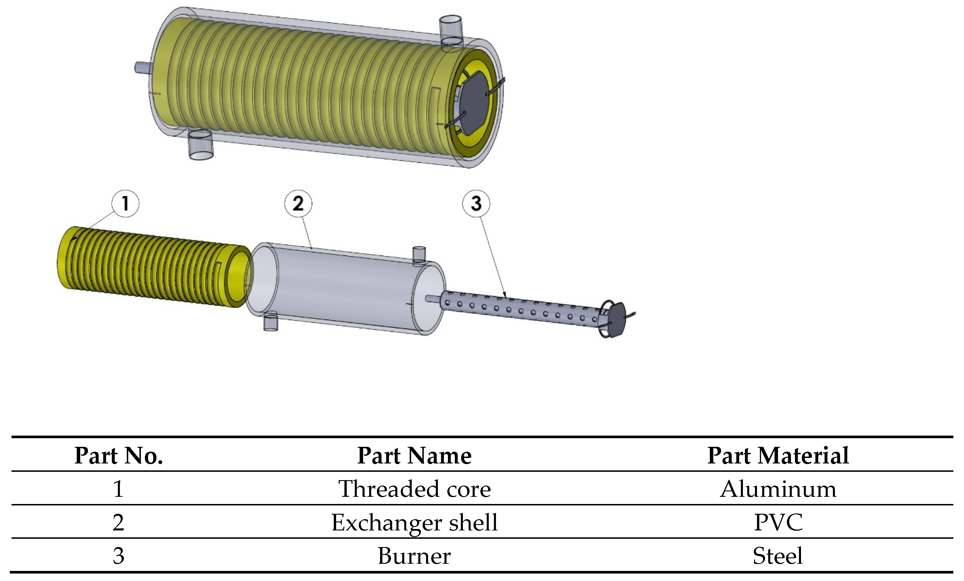
In the present work, considering the mentioned problems, a particular type of instantaneous water heater was designed to minimize the reported drawbacks. The schematic and specifications of the designed STHE are presented in Figure 1.
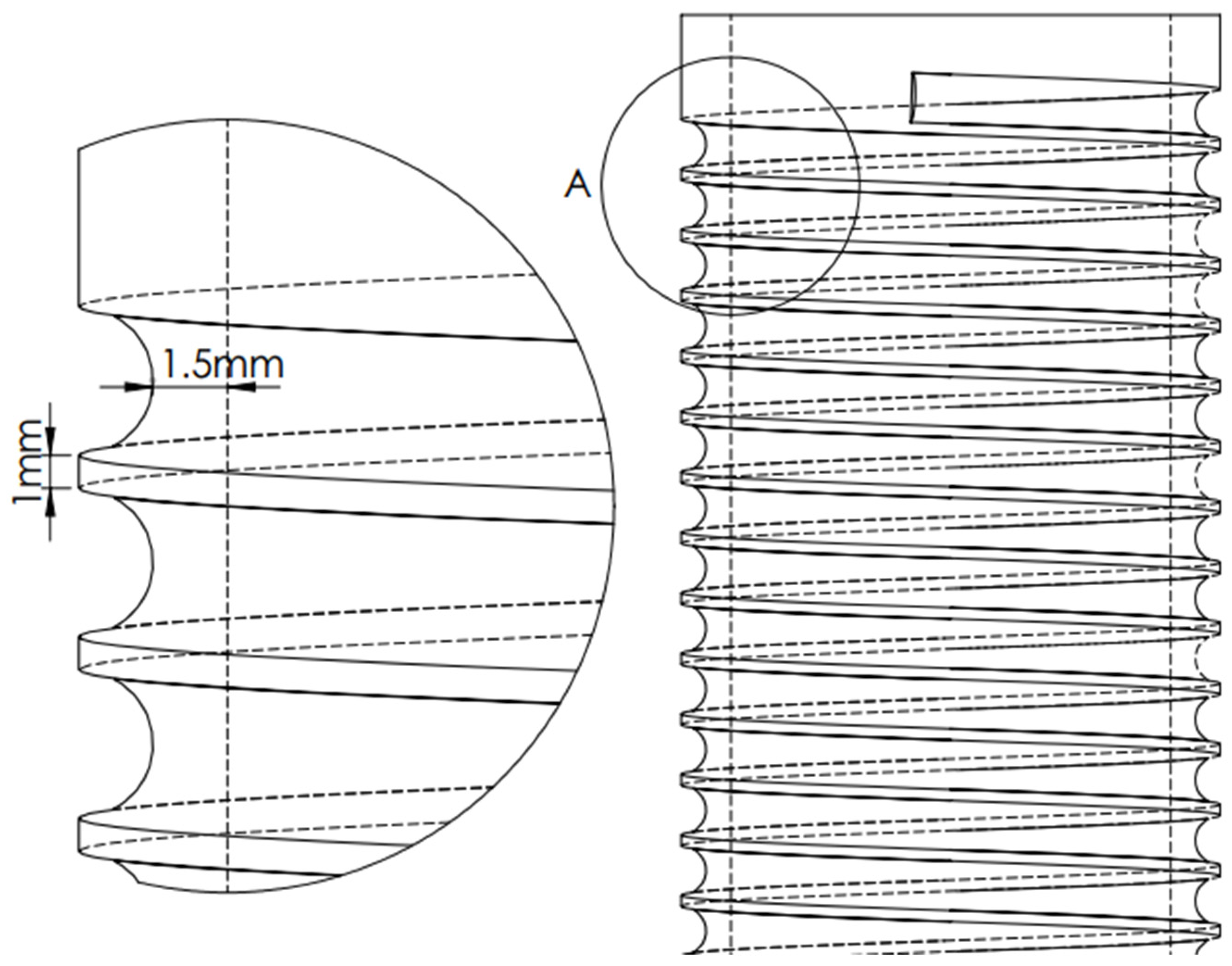
For this purpose, an aluminum tube 30 cm in length and 5 mm in wall thickness, which was threaded to a depth of 3.5 mm, was used. The final thickness of the tube in which the fluid flowed was 1.5 mm (Figure 2). A PVC pipe that coated the aluminum tube like an insulator was used to manufacture the shell of the HE (Figure 1). Considering the research topic, the main objective was to properly find the factors that impose the most considerable impacts on the efficiency of the HE. We further sought to identify the factors that impose significant effects on one another, as well as the response variable, and then devise them to formulate a solution for the design and optimization of the HE.
A number of important factors that affect the design and manufacturing of an instantaneous water heater include heat transfer area, the HE’s material, the HE’s wall thickness, exhaust temperature, the geometry of the HE, and water flow rate (WFR).
The proposed instantaneous water heater was designed and manufactured considering all of these factors. In order to optimize the HE, one should select a number of effective adjustable factors and investigate HE performance at different levels of the selected factors. The best approach to such an assessment is offered by the response surface methodology (RSM). The following factors were selected for optimizing the instantaneous water heater: heat transfer area (i.e., fin number), exhaust temperature (i.e., chimney diameter), and WFR.
Based on the investigation results and considering the instantaneous water heater’s geometry and scale, we opted for the circular fins for the HE. Additionally, inverse conical chimneys were designed and manufactured with three different base diameters.
Since this is a field study, the required data were collected through actual observations. The topic should be analyzed on a large scale, and an ideal (optimal) solution cannot be achieved unless accurate details of the topic are collected and verified. The data were furnished in the “Garman Gas Toos” laboratory, where multiple tests were conducted on the designed instantaneous water heater. In these tests, an attempt was made to establish identical sets of conditions when evaluating the dependent variables (i.e., responses), namely efficiency and HTR. To evaluate the efficiency, the gas consumption rate (mc) in an ideal case was set to 40 L/min. A thermometer was used to calculate the temperature difference between the water and the HE’s surface. In the experimental work, tests were performed at different levels of the three major factors, i.e., fin number, exhaust, and flow rate. The observed values of water temperature difference, WFR, and hot water output time were recorded (Table 1).
2.1. RSM
RSM refers to a set of statistical procedures and practical mathematics used for building experimental models [32,33]. This methodology seeks to optimize a particular response (i.e., output variable) that is affected by multiple independent variables (i.e., input variables) [34,35]. An experiment herein refers to a series of runs herein referred to as an implementation. In each experiment, input variables were changed to see the resultant change in the response variable. Design of experiment (DoE) by RSM was first introduced in 1950 for particular applications in chemical industries. Later on, however, RSM was widely utilized for quality enhancement, product design, and uncertainty study. There are two common approaches to the DoE via RSM, including CCD and Box–Behnken design (BBD).
In RSM, once finished with identifying the most effective variables on the response, regression analysis is devised to propose a mathematical equation (usually a quadratic function) to relate the response variable to the effective factors. Next, investigations are conducted to find the levels of the factors at which the response is optimal. RSM is an iterative procedure. Once an approximation model is found, it is tested, as per the goodness-of-fit, to see whether the response is acceptable or not. Should the response not be established, the approximation process is restarted to perform more experiments [36].
2.2. DoE Using CCD
In this research, a three-factor design including fin number (A, ranging from 1 to 6 fins per unit area), exhaust outlet diameter (B, ranging from 2 to 4 cm), and WFR (C, ranging from 2 to 14 L/min) was formulated based on CCD with 6 central points, taking efficiency and HTR as the response variables (Table 2). Design Expert 13 software was employed for the DoE, while the central points were devised to evaluate the experimentation error and repeatability of the data.
The HTR (Q) and efficiency (η) responses were calculated from Equations (1) and (2), respectively [37,38].
where h, , and are the convective coefficient, area, and temperature difference, respectively. In addition, , R, and C denote gas consumption, the heat value of the fuel, and specific heat capacity, respectively.
2.3. DoE and Presentation of the Mathematical Model
Once finished selecting the design, the equation of the model was determined, and its coefficients were predicted. The model used with RSM is usually a complete quadratic model. A quadratic model can be expressed as Equation (3) [39].
in which y is the predicted response, B0 is a constant coefficient, n is the number of variables, Bi is a linear coefficient, Bij denotes an interaction coefficient, Bii refers to quadratic coefficients, and Xi and Xj are coded values of the independent variables (e.g., factors) [40]. Each variable must be coded within its range to normalize it into a [–1, 1] interval. This is conducted to ensure that the regression analysis works properly, because independent variables may come in different units or different ranges. The normalization can be achieved through Equation (4) [39].
where is the dimensionless central value of the ith variable, Xi is the natural value of the ith variable, and Xmax and Xmin are the maximum and minimum levels of the ith variable, respectively.
Coefficients of Equation (3) can be obtained with a regression analysis coupled with the least squares method. Next, one should verify the model using the testing data. A variety of methods have been proposed to perform this task, including residual analysis, predicted root-mean-square error, and an incompliance test. The general predictive power of the model was assessed by the determination coefficient (R2), while its statistical significance was examined by an F-test (i.e., F-value). The significance of different regression coefficients was also calculated using the so-called t-test. It should be considered that R2 alone is not able to clarify the model accuracy adequately, as it expresses the variations around the mean response [41]. Accordingly, practitioners use another index called adjusted R2 (R2adj). For calculating this index, in contrast to R2, the average sum of squares is utilized as a substitute for the sum of squares. Equations (5) and (6) express the relations for calculating these parameters.
where K and N refer to the number of predicted variables and the total number of observations, respectively. Additionally, SS and DF stand for sum of squares and degree of freedom, respectively. R2 measures the quality of fitting the experimental data to the model, while R2adj is an adjusted representation of R2, into which the degree of freedom is further incorporated. The higher the number of data points and the closer the values of R2 and R2adj are to 1, the more acceptable the fitting results will be.
3. Results and Discussion
Factors affecting the efficiency and HTR of the HE, including fin number, exhaust outlet diameter, and WFR, were considered. Entering the ranges of the considered factors into the software and running CCD, a total of 20 experiments were proposed, of which 6 tests referred to central points, with the remaining 14 experiments relating to non-central points (Table 3). Experiments were performed at the laboratory of “Garman Gas Toos” Company, and the initial and final amounts of water (upon passing through the instantaneous water heaters) were measured. The assumptions of the experiments included constant environment temperature, the steady flow rate of gas, and low conductive thermal resistance of the heater body. Additionally, we tried to consider the assumptions of “design of experiments”. Furthermore, the order of experiments has been performed randomly to ensure the independence of experimental errors. According to these observations and applying Equations (1) and (2), the values of efficiency and HTR were obtained. Measured values of the response variables (i.e., efficiency and HTR) are reported in Table 3.
3.1. Final Equations for Obtaining the Effect of Factors on Responses
The approximated quadratic equations for relating the response variables to the factors are expressed in the following.
The positive sign behind the terms of these equations indicates their synergetic effects, while negative signs characterize inversely-acting actors. The coefficients of the model for the response were estimated by multivariate regression analysis techniques incorporated into the RSM. The models had their goodness-of-fit evaluated based on relevant correlation coefficients.
3.2. Results of ANOVA for the Efficiency Response
ANOVA was conducted for the efficiency response and the factors by the software, with their results listed in Table 4. The p-value for fin number (A), WFR (C), mutual effect of fin number and WFR (AC), and squared fin number (A2), exhaust outlet diameter (B2), and WFR (C2) were close to zero, indicating their strong impacts on the response variable. The p-value for the mutual effect of fin number and exhaust outlet diameter (AB) was calculated at 0.022, i.e., below the significance level of 0.05, indicating the acceptable significance of this factor. The obtained p-values for the exhaust outlet diameter (B) and the mutual effect of the exhaust outlet diameter and WFR (BC) were higher than 0.05, indicating the insignificant impacts of these factors, especially for the exhaust outlet diameter.
According to Table 5, the obtained quadratic equation ended up with an R2adj of 0.9835, indicating proper agreement of the experimental data with the predicted results by the model developed for optimizing the HE.
3.3. Summary of Statistical Results for the HTR Response
ANOVA was conducted for the HTR response and the factors by the software, with their results listed in Table 6. The p-value for fin number (A), WFR (C), mutual effect of fin number and WFR (AC), and squared fin number (A2), exhaust outlet diameter (B2), and WFR (C2) were close to zero, while p-value for the mutual effect of fin number and exhaust outlet diameter (AB) was calculated at 0.0427, i.e., below the significance level of 0.05. These results indicate the significance of the mentioned variables for optimizing the HE. The exhaust outlet diameter (B) and the mutual effect of the exhaust outlet diameter and WFR (BC) exhibited p-values higher than 0.05, indicating their insignificant effects.
According to Table 7, the obtained quadratic equation ended up with an R2adj of 0.9992, indicating proper agreement of the experimental data with the predicted results by the developed model.
3.4. Graphical Demonstration of Response Surface and Contour Lines
In order to better demonstrate the effects of the factors on the response variable, it is beneficial to present 3D graphs and contour lines. A contour line indicates different compositions of the effective factors for which the response is the same, making it suitable for finding the ranges of the factors for which the response is optimal.
Using these graphical representations, one can investigate the effects of different factors on the response at different points. Subsequently, by identifying the intersection of different variables, it is possible to find and record the accurate values of the measured response.
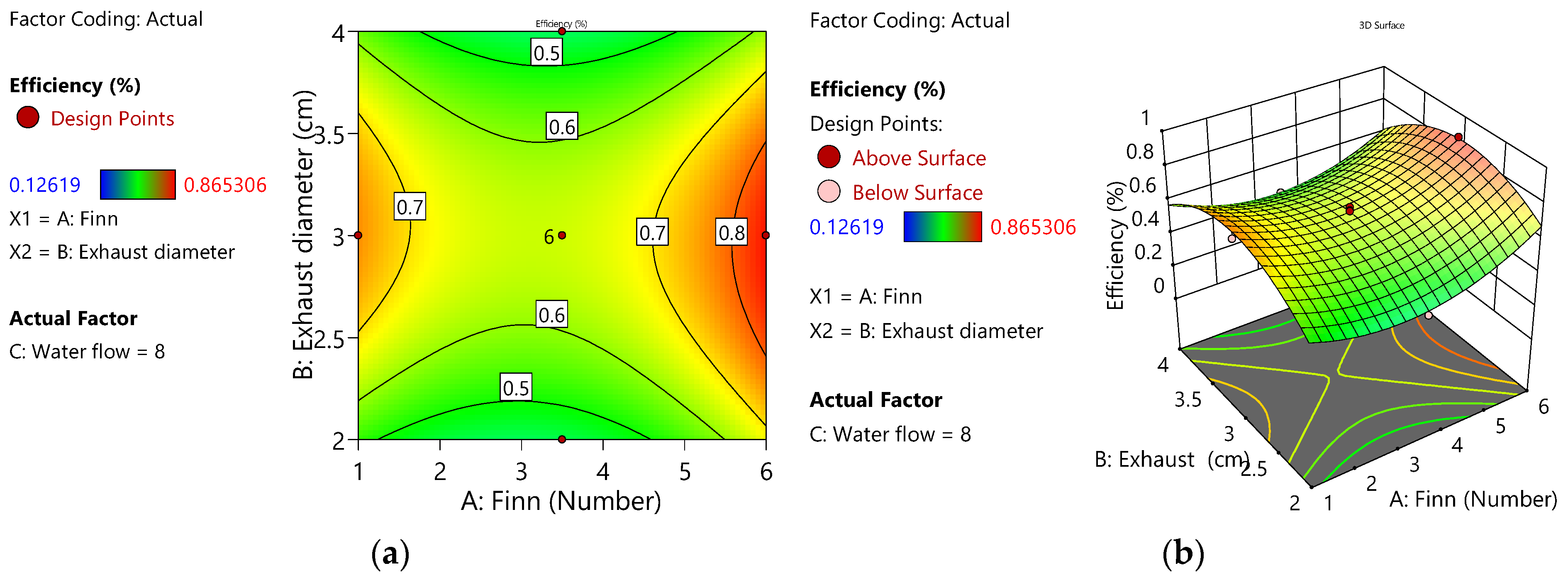
3.5. Response Surface and Contour Lines for Efficiency Response
Figure 3a shows the response surface for efficiency as a function of fin number and WFR. In this figure, the red color indicates a stronger effect of the corresponding factor on the response. Accordingly, as one moves toward red zones, the response value increases, while the blue color reflects a decrease in the response value. Figure 3b shows contour lines for the efficiency as a function of fin number and WFR. Based on this representation, the highest fin number (i.e., six) coupled with a WFR of about 8 L/min led to the highest efficiency response. The greenish zones indicate the weakest impact on the response.
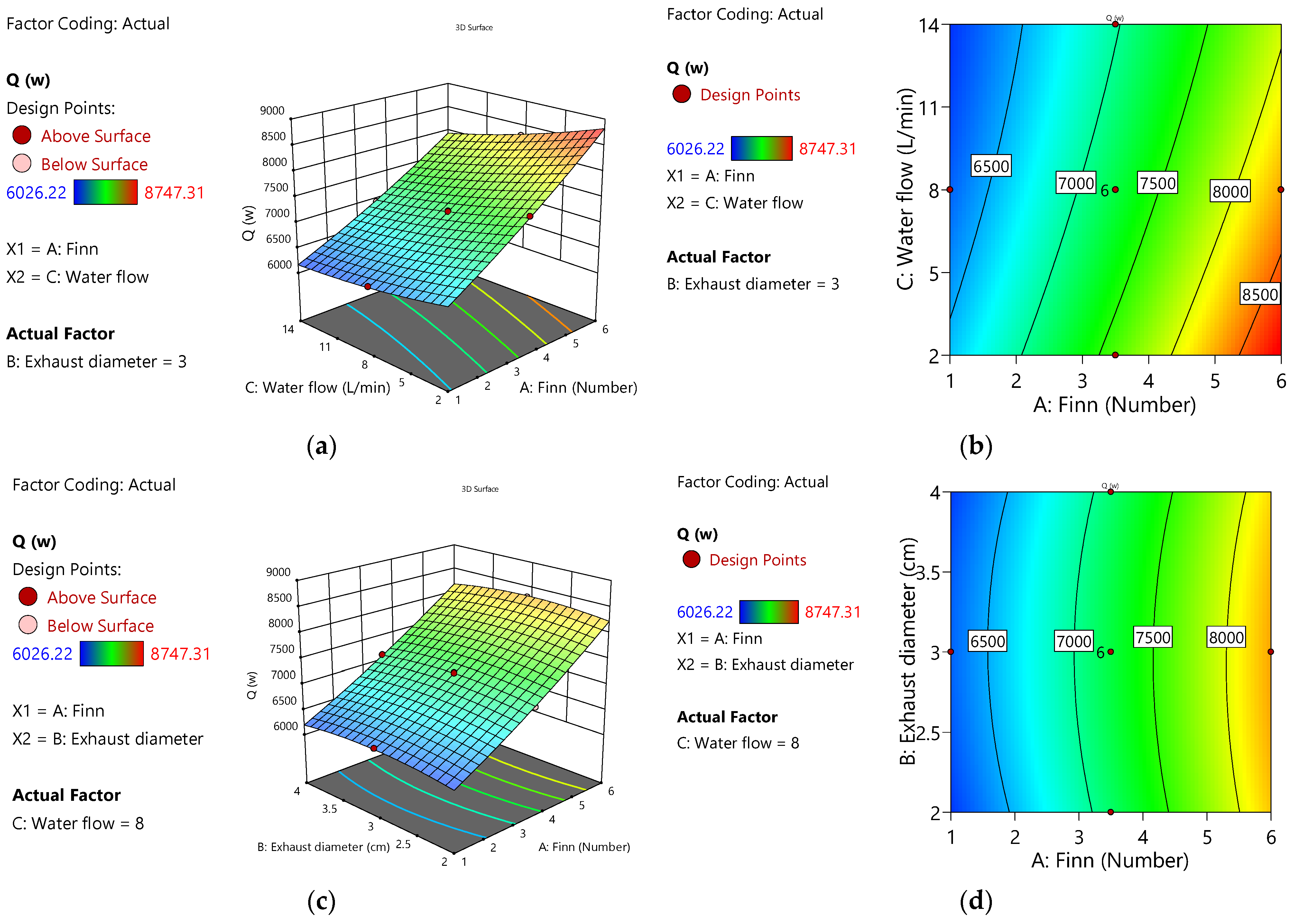
3.6. Response Surface and Contour Lines for HTR Response
Figure 4a shows the response surface for HTR as a function of fin number and WFR. In this figure, the red color indicates a more substantial effect of the corresponding factor on the response. Figure 4b shows contour lines for the HTR as a function of fin number and WFR. From these two figures, it is evident that the HTR is maximal, with a maximum fin number (i.e., six) coupled with a WFR of about 2 L/min.
3.7. Optimization
Using the utility function in the Design Expert 13 software, a total of 11 solutions were presented for achieving the optimal levels of efficiency and HTR of the HE at a utility index of 0.94 for the testing data. The solutions proposed by the utility functions showed that optimal levels of efficiency and HTR were expected with six fins, an exhaust outlet diameter of 3 cm, and a WFR of 6 L/min. The software determined the optimal values of the independent variables to maximize the response variables. In this research, optimality was defined as the maximization of efficiency and HTR responses. At the optimal points, the expected values of efficiency and HTR were obtained as 85% and 8478 W, respectively (Table 8). Considering the optimal conditions, it was observed that the lowest efficiency was related to WFRs above 13 L/min or below 3 L/min, while the lowest HTRs were measured when the fin number was below two. In this research, we figured out that the exhaust outlet diameter imposes no remarkable impact on the response variables. In most of the solutions proposed by the software, the fin number was set to maximum (i.e., six), the exhaust outlet diameter was set to 3 cm, and the WFR was set to something between 5 and 6 L/min. Considering the optimal conditions proposed by the software, it is recommended to use more fins with a WFR of 5–6 L/min to increase the efficiency and HTR in the designed instantaneous water heater.
4. Conclusions
In this research, heat transfer in an STHE (as a type of instantaneous water heater) was experimentally investigated. First, factors affecting the heat transfer in this type of instantaneous water heater were identified. Next, the identified factors were experimentally analyzed to improve the research objectives, namely the efficiency and HTR of the HE. Additionally, in the previous studies, the researchers focused on the efficiency and heat transfer enhancement of HEs, while the physical problems in traditional instantaneous water heaters (such as leakage, sedimentation, and rusting) have received less attention. In this research, by identifying and investigating the causes of failure and return of instantaneous water heaters (brand: Garman Gas Toos), it was decided to design and manufacture a new HE to minimize these issues. The geometric shape of the HE is designed so that the shell can be easily separated from the aluminum thread. Additionally, the aluminum material of the thread has caused it to have the lowest amount of rust. In this study, the effects of fin number, exhaust outlet diameter, and WFR on the efficiency and HTR of the instantaneous water heater were investigated. Moreover, optimal levels of the factors were evaluated by RSM. Under optimal conditions in terms of fin number (six), exhaust outlet diameter (3 cm), and WFR (6 L/min), we ended up with an HE efficiency and heat transfer of 85% and 8480 W, respectively. Experiments show that the factors of fin number and water flow rate have significant effects on the efficiency and heat transfer rate, while the exhaust diameter factor has a very small effect compared with the other two factors. The findings of the present research can be highly advantageous to optimize and improve instantaneous water heaters used in different industries and domestic environments, helping reduce energy consumption in these areas.
Author Contributions
Conceptualization, P.R.; Methodology, H.R.M. and A.A.D.; Formal analysis, H.R.M. and A.A.D.; Investigation, P.R., H.R.M. and A.A.D.; Writing—original draft, P.R.; Writing—review & editing, P.R., H.R.M. and A.A.D. All authors have read and agreed to the published version of the manuscript.
Funding
P. Rezaei thanks the “Garman Gas Toos” company for the financial support (project number 29/20429).
Data Availability Statement
The data presented in this study are available on request from the corresponding author.
Acknowledgments
Additionally, the authors appreciate Alireza Dehghani, Sina Sheybani, and Ishaq Nia for their guidance.
Conflicts of Interest
The authors declare no conflict of interest.
Nomenclature
| η | Efficiency (%) |
| m | Water mass flow rate (L/min) |
| mc | Gas consumption (kcal/min) |
| R | Fuel heat value (kcal/m3) |
| C | Specific heat capacity of water (J/kg.°C) |
| Q | Heat transfer rate (W) |
| h | Heat transfer coefficient (W/m2k) |
| Heat transfer area (m2) | |
| ΔT | Temperature difference (k) |
Abbreviations
| CCD | Central Composite Design |
| DoE | Design of Experiments |
| HE | Heat Exchanger |
| HTR | Heat Transfer Rate |
| NPCM | Nano-Encapsulated Phase Change Material |
| RSM | Response Surface Methodology |
| STHE | Spiral-Tube Heat Exchanger |
| WFR | Water Flow Rate |
References
- Arabkoohsar, A.; Khosravi, M.; Alsagri, A.S. Effect of various twisted-tape designs on the thermal and environmental performance of line-heaters in city gate stations. Int. J. Heat Mass Transf. 2020, 148, 119123. [Google Scholar] [CrossRef]
- Amiri Delouei, A.; Karimnejad, S.; Gharajeh, A.; Sajjadi, H.; Atashafrooz, M.; Xie, G.; Arabkoohsar, A. Bath heaters using alternative heat transfer medium: A thermo-economic analysis. J. Braz. Soc. Mech. Sci. Eng. 2023, 45, 73. [Google Scholar] [CrossRef]
- Bayati Chaleshtari, M.H.; Jafari, M.; Khoramishad, H.; Craciun, E.M. Mutual Influence of Geometric Parameters and Mechanical Properties on Thermal Stresses in Composite Laminated Plates with Rectangular Holes. Mathematics 2021, 9, 311. [Google Scholar] [CrossRef]
- Amiri Delouei, A.; Sajjadi, H.; Ahmadi, G. Ultrasonic Vibration Technology to Improve the Thermal Performance of CPU Water-Cooling Systems: Experimental Investigation. Water 2022, 14, 4000. [Google Scholar] [CrossRef]
- Amiri Delouei, A.; Atashafrooz, M.; Sajjadi, H.; Karimnejad, S. The thermal effects of multi-walled carbon nanotube concentration on an ultrasonic vibrating finned tube heat exchanger. Int. Commun. Heat Mass Transf. 2022, 135, 106098. [Google Scholar] [CrossRef]
- Shen, G.; Ma, L.; Zhang, S.; Zhang, S.; An, L. Effect of ultrasonic waves on heat transfer in Al2O3 nanofluid under natural convection and pool boiling. Int. J. Heat Mass Transf. 2019, 138, 516–523. [Google Scholar] [CrossRef]
- Abdelmagied, M. Thermal performance characteristics of a triple spiral tube heat exchanger. Chem. Eng. Process. Process Intensif. 2020, 149, 107707. [Google Scholar] [CrossRef]
- Abdelmagied, M. Experimental study of a triple spirally coiled tube heat exchanger thermo-fluid characteristics. Appl. Therm. Eng. 2020, 180, 115803. [Google Scholar] [CrossRef]
- Abraham, P.; Sharqawy, M.H.; Shawkat, M.E. Thermal and hydraulic characteristics of multiple row spiral finned tube heat exchangers. Int. J. Refrig. 2021, 130, 56–66. [Google Scholar] [CrossRef]
- Kiatpachai, P.; Kaewkamrop, T.; Mesgarpour, M.; Ahn, H.S.; Dalkılıç, A.S.; Mahian, O.; Wongwises, S. Air-side performance of embedded and welded spiral fin and tube heat exchangers. Case Stud. Therm. Eng. 2022, 30, 101721. [Google Scholar] [CrossRef]
- Kiatpachai, P.; Keawkamrop, T.; Asirvatham, L.G.; Mesgarpour, M.; Dalkılıc, A.S.; Ahn, H.S.; Mahian, O.; Wongwises, S. An experimental study of the air-side performance of a novel louver spiral fin-and-tube heat exchanger. Alex. Eng. J. 2022, 61, 9811–9818. [Google Scholar] [CrossRef]
- Keawkamrop, T.; Mesgarpour, M.; Dalkılıç, A.S.; Ahn, H.S.; Mahian, O.; Wongwises, S. Effect of the segmented fin height on the air-side performance of serrated welded spiral fin-and-tube heat exchangers. Case Stud. Therm. Eng. 2022, 35, 102128. [Google Scholar] [CrossRef]
- Moria, H. A comprehensive geometric investigation of non-circular cross section spring-wire turbulator through the spiral-tube based heat exchangers. Results Eng. 2023, 17, 100906. [Google Scholar] [CrossRef]
- Zeinali, S.; Neshat, E. Energy, exergy, economy analysis and geometry optimization of spiral coil heat exchangers. Case Stud. Therm. Eng. 2023, 42, 102708. [Google Scholar] [CrossRef]
- Pongsoi, P.; Pikulkajorn, S.; Wongwises, S. Heat transfer and flow characteristics of spiral fin-and-tube heat exchangers: A review. Int. J. Heat Mass Transf. 2014, 79, 417–431. [Google Scholar] [CrossRef]
- Liang, B.; Chen, M.; Fu, B.; Li, H. Investigation on the thermal and flow performances of a vertical spiral-tube ground heat exchanger in sand combined with kaolin additive. Energy Build. 2019, 190, 235–245. [Google Scholar] [CrossRef]
- Liang, B.; Chen, M.; Fu, B.A.; Guan, J. Thermal and flow characteristics in a vertical spiral-type ground heat exchanger based on linear non-equilibrium thermodynamic principle. Energy Build. 2022, 266, 112111. [Google Scholar] [CrossRef]
- Dinh, B.H.; Kim, Y.S.; Yoon, S. Experimental and numerical studies on the performance of horizontal U-type and spiral-coil-type ground heat exchangers considering economic aspects. Renew. Energy 2022, 186, 505–516. [Google Scholar] [CrossRef]
- Yoon, S.; Kim, M.J.; Jeon, J.S.; Jung, Y.B. Significance evaluation of performance factors on horizontal spiral-coil ground heat exchangers. J. Build. Eng. 2021, 35, 102044. [Google Scholar] [CrossRef]
- Yang, W.; Xu, R.; Wang, F.; Chen, S. Experimental and numerical investigations on the thermal performance of a horizontal spiral-coil ground heat exchanger. Renew. Energy 2020, 147, 979–995. [Google Scholar] [CrossRef]
- Suzuki, M.; Yoneyama, K.; Amemiya, S.; Oe, M. Development of a Spiral Type Heat Exchanger for Ground Source Heat Pump System. Energy Procedia 2016, 96, 503–510. [Google Scholar] [CrossRef] [Green Version]
- Arjmandi, H.; Amiri, P.; Saffari Pour, M. Geometric optimization of a double pipe heat exchanger with combined vortex generator and twisted tape: A CFD and response surface methodology (RSM) study. Therm. Sci. Eng. Prog. 2020, 18, 100514. [Google Scholar] [CrossRef]
- Xie, C.; Yan, G.; Ma, Q.; Elmasry, Y.; Singh, P.K.; Algelany, A.M.; Wae-hayee, M. Flow and heat transfer optimization of a fin-tube heat exchanger with vortex generators using Response Surface Methodology and Artificial Neural Network. Case Stud. Therm. Eng. 2022, 39, 102445. [Google Scholar] [CrossRef]
- Zhou, Y.; He, K.; Alizadeh, A.; AL-Khafaji, M.O.; Alawadi, A.H.R.; Maleki, H.; Ismail, M.M.; Shamsborhan, M.; Mohammed, S.H.; Adhab, A.H.; et al. Computational fluid dynamics and multi-objective response surface methodology optimization of perforated-finned heat sinks. J. Taiwan Inst. Chem. Eng. 2023, 104823. [Google Scholar] [CrossRef]
- Lin, M.C.; Lin, R.F. Design Analysis of Heat Sink Using the Field Synergy Principle and Multitarget Response Surface Methodology. Energies 2022, 15, 8399. [Google Scholar] [CrossRef]
- Chananipoor, A.; Azizi, Z.; Raei, B.; Tahmasebi, N. Optimization of the thermal performance of nano-encapsulated phase change material slurry in double pipe heat exchanger: Design of experiments using response surface methodology (RSM). J. Build. Eng. 2021, 34, 101929. [Google Scholar] [CrossRef]
- Liu, P.; Han, H.; Bao, Z. Multi-objective optimization of fuel-air tube-in-tube helical coil heat exchangers for cooled cooling air system applied in aeroengines. Aerosp. Sci. Technol. 2022, 130, 107933. [Google Scholar] [CrossRef]
- Liu, S.; Huang, W.; Bao, Z.; Zeng, T.; Qiao, M.; Meng, J. Analysis, prediction and multi-objective optimization of helically coiled tube-in-tube heat exchanger with double cooling source using RSM. Int. J. Therm. Sci. 2021, 159, 106568. [Google Scholar] [CrossRef]
- Dagdevir, T. Multi-objective optimization of geometrical parameters of dimples on a dimpled heat exchanger tube by Taguchi based Grey relation analysis and response surface method. Int. J. Therm. Sci. 2022, 173, 107365. [Google Scholar] [CrossRef]
- Liu, Q.; Tao, Y.; Shi, L.; Zhou, T.; Huang, Y.; Peng, Y.; Wang, Y.; Tu, J. Parametric optimization of a spiral ground heat exchanger by response surface methodology and multi-objective genetic algorithm. Appl. Therm. Eng. 2023, 221, 119824. [Google Scholar] [CrossRef]
- Serageldin, A.A.; Radwan, A.; Katsura, T.; Sakata, Y.; Nagasaka, S.; Nagano, K. Parametric analysis, response surface, sensitivity analysis, and optimization of a novel spiral-double ground heat exchanger. Energy Convers. Manag. 2021, 240, 114251. [Google Scholar] [CrossRef]
- Hadiyat, M.A.; Sopha, B.M.; Wibowo, B.S. Response Surface Methodology Using Observational Data: A Systematic Literature Review. Appl. Sci. 2022, 12, 10663. [Google Scholar] [CrossRef]
- Samson, J.S.C.; Murugan, K.; Abhra, P.R.; Makarand, U.; Venugopal, N.; Gnanasekaran, S. Optimization of process parameters using response surface methodology: A review. Mater. Today Proc. 2021, 37, 1301–1304. [Google Scholar] [CrossRef]
- Mäkelä, M. Experimental design and response surface methodology in energy applications: A tutorial review. Energy Convers. Manag. 2017, 151, 630–640. [Google Scholar] [CrossRef]
- Tsai, C.Y.; Kim, J.; Jin, F.; Jun, M.; Cheong, M.; Yammarino, F.J. Polynomial regression analysis and response surface methodology in leadership research. Leadersh. Q. 2022, 33, 101592. [Google Scholar] [CrossRef]
- Montgomery, D.C. Design and Analysis of Experiments, 6th ed.; John Wiley and Sons: New York, NY, USA, 2005. [Google Scholar]
- Bergman, T.L.; Lavine, A.S.; Incropera, F.P.; Dewitt, D.P. Fundamentals of Heat and Mass Transfer; John Wiley & Sons: New York, NY, USA, 2011. [Google Scholar]
- Holman, J. Heat Transfer; McGraw-Hill Education: New York, NY, USA, 2009. [Google Scholar]
- Akyürek, E.F.; Geliş, K.; Şahin, B.; Manay, E. Experimental Analysis for Heat Transfer of Nanofluid with Wire Coil Turbulators in a Concentric Tube Heat Exchanger. Results Phys. 2018, 9, 376–389. [Google Scholar] [CrossRef]
- Yang, Z.H.; Huang, J.; Zeng, G.M.; Ruan, M.; Zhou, C.S.; Li, L.; Rong, Z.G. Optimization of flocculation conditions for kaolin suspension using the composite flocculant of MBFGA1 and PAC by response surface methodology. Bioresour. Technol. 2009, 100, 4233–4239. [Google Scholar] [CrossRef]
- Esfe, M.H.; Motallebi, S.M.; Hatami, H.; Amiri, M.K.; Esfandeh, S.; Toghraie, D. Optimization of density and coefficient of thermal expansion of MWCNT in thermal oil nanofluid and modeling using MLP and response surface methodology. Tribol. Int. 2023, 183, 108410. [Google Scholar] [CrossRef]
Figure 1.
Schematic and specifications of the designed STHE.

Figure 2.
A view of the internal structure of the aluminum threaded core. The figure on the right is a magnification of the “A” region.
Figure 2.
A view of the internal structure of the aluminum threaded core. The figure on the right is a magnification of the “A” region.

Figure 3.
(a) Response surface representing efficiency as a function of fin number and WFR, and (b) contour lines representing efficiency as a function of fin number and WFR.
Figure 3.
(a) Response surface representing efficiency as a function of fin number and WFR, and (b) contour lines representing efficiency as a function of fin number and WFR.

Figure 4.
(a) Response surface representing HTR as a function of fin number and WFR, (b) contour lines representing HTR as a function of fin number and WFR, (c) response surface representing HTR as a function of fin number and exhaust outlet diameter, and (d) contour lines representing HTR as a function of fin number and exhaust outlet diameter.


Table 1.
Obtained values of efficiency and HTR at different levels of the studied factors.
| Test No. | Tube’s Internal Area (m2) | Fin Area (m2) | Total Area (m2) | Fin Numbers | Exhaust Outlet Diameter (cm) | Flow Rate(L/min) | Efficiency (%) | HTR (W) |
|---|---|---|---|---|---|---|---|---|
| 1 | 0.0753 | 0.01673 | 0.09203 | 3.5 | 2 | 8 | 40.8616780 | 7101.352304 |
| 2 | 0.0753 | 0.02868 | 0.10398 | 6 | 4 | 14 | 16.8253968 | 7838.943021 |
| 3 | 0.0753 | 0.02868 | 0.10398 | 6 | 2 | 14 | 25.2380952 | 7867.329561 |
| 4 | 0.0753 | 0.00478 | 0.08008 | 1 | 4 | 14 | 23.5555556 | 6054.636588 |
| 5 | 0.0753 | 0.01673 | 0.09203 | 3.5 | 4 | 8 | 43.2653061 | 7113.914399 |
| 6 | 0.0753 | 0.01673 | 0.09203 | 3.5 | 3 | 8 | 64.8979592 | 7226.973254 |
| 7 | 0.0753 | 0.01673 | 0.09203 | 3.5 | 3 | 14 | 21.031746 | 6950.607164 |
| 8 | 0.0753 | 0.02868 | 0.10398 | 6 | 4 | 2 | 37.2562358 | 8662.152681 |
| 9 | 0.0753 | 0.01673 | 0.09203 | 3.5 | 3 | 2 | 36.0544218 | 7641.522389 |
| 10 | 0.0753 | 0.00478 | 0.08008 | 1 | 3 | 8 | 72.1088435 | 6321.351036 |
| 11 | 0.0753 | 0.01673 | 0.09203 | 3.5 | 3 | 8 | 65.3786848 | 7229.485673 |
| 12 | 0.0753 | 0.01673 | 0.09203 | 3.5 | 3 | 8 | 65.3786848 | 7229.485673 |
| 13 | 0.0753 | 0.01673 | 0.09203 | 3.5 | 3 | 8 | 65.3786848 | 7229.485673 |
| 14 | 0.0753 | 0.00478 | 0.08008 | 1 | 4 | 2 | 24.0362812 | 6430.660236 |
| 15 | 0.0753 | 0.00478 | 0.08008 | 1 | 2 | 14 | 12.6190476 | 6026.216196 |
| 16 | 0.0753 | 0.01673 | 0.09203 | 3.5 | 3 | 8 | 65.3786848 | 7229.485673 |
| 17 | 0.0753 | 0.02868 | 0.10398 | 6 | 2 | 2 | 40.861678 | 8747.312301 |
| 18 | 0.0753 | 0.00478 | 0.08008 | 1 | 2 | 2 | 25.2380952 | 6452.522076 |
| 19 | 0.0753 | 0.01673 | 0.09203 | 3.5 | 2 | 8 | 67.3015873 | 7239.535349 |
| 20 | 0.0753 | 0.02868 | 0.10398 | 6 | 2 | 8 | 86.5306122 | 8293.127661 |
Table 2.
Effective factors on the HE and their levels.
| Factor | Unit | Min. | Max. |
|---|---|---|---|
| Fins | Count per unit area | 1 | 6 |
| Water flow rate | L/min | 2 | 14 |
| Exhaust | cm | 2 | 4 |
Table 3.
Experimental results and their comparison with the corresponding predicted responses.
| Std | Run | Space Type | Factor 1 | Factor 2 | Factor 3 | Response 1 | Response 2 | ||
|---|---|---|---|---|---|---|---|---|---|
| A: Fin (Number) | B: Exhaust Diameter (cm) | C: Water Flow (L/min) | Predicted Value | Efficiency (%) | Predicted Value | Q (W) | |||
| 11 | 1 | Axial | 3.5 | 2 | 8 | 43.58 | 40.8617 | 7118.83 | 7101.35 |
| 8 | 2 | Factorial | 6 | 4 | 14 | 19.16 | 16.8254 | 7829.27 | 7838.94 |
| 6 | 3 | Factorial | 6 | 2 | 14 | 22.74 | 25.2381 | 7846.17 | 7867.33 |
| 7 | 4 | Factorial | 1 | 4 | 14 | 20.50 | 23.5556 | 6078.18 | 6080.87 |
| 12 | 5 | Axial | 3.5 | 4 | 8 | 43.61 | 43.2653 | 7105.19 | 7113.91 |
| 20 | 6 | Center | 3.5 | 3 | 8 | 64.60 | 64.898 | 7227.82 | 7226.97 |
| 14 | 7 | Axial | 3.5 | 3 | 14 | 23.66 | 21.0317 | 6975.89 | 6938.05 |
| 4 | 8 | Factorial | 6 | 4 | 2 | 35.90 | 37.2562 | 8664.27 | 8662.15 |
| 13 | 9 | Axial | 3.5 | 3 | 2 | 36.49 | 36.0544 | 7612.44 | 7641.52 |
| 9 | 10 | Axial | 1 | 3 | 8 | 75.93 | 72.1088 | 6301.90 | 6321.35 |
| 19 | 11 | Center | 3.5 | 3 | 8 | 64.60 | 65.3787 | 7227.82 | 7229.49 |
| 18 | 12 | Center | 3.5 | 3 | 8 | 64.60 | 65.3787 | 7227.82 | 7229.49 |
| 16 | 13 | Center | 3.5 | 3 | 8 | 64.60 | 65.3787 | 7227.82 | 7229.49 |
| 3 | 14 | Factorial | 1 | 4 | 2 | 25.77 | 24.0363 | 6449.63 | 6430.66 |
| 5 | 15 | Factorial | 1 | 2 | 14 | 13.21 | 12.619 | 6021.91 | 6026.22 |
| 17 | 16 | Center | 3.5 | 3 | 8 | 64.60 | 65.3787 | 7227.82 | 7229.49 |
| 2 | 17 | Factorial | 6 | 2 | 2 | 43.15 | 40.8617 | 8747.82 | 8747.31 |
| 1 | 18 | Factorial | 1 | 2 | 2 | 22.14 | 25.2381 | 6460.01 | 6452.52 |
| 15 | 19 | Center | 3.5 | 3 | 8 | 64.60 | 67.3016 | 7227.82 | 7239.54 |
| 10 | 20 | Axial | 6 | 3 | 8 | 85.77 | 86.5306 | 8321.34 | 8293.13 |
Table 4.
Analysis of variance (ANOVA) for the efficiency response.
| Source | Sum of Squares | df | Mean Square | F-Value | p-Value | |
|---|---|---|---|---|---|---|
| Model | 0.9208 | 9 | 0.1023 | 126.85 | <0.0001 | significant |
| A-Fin | 0.0242 | 1 | 0.0242 | 29.96 | 0.0003 | |
| B-Exhaust diameter | 1.44 × 10⁻⁷ | 1 | 1.44 × 10⁻⁷ | 0.0002 | 0.9896 | |
| C-Water flow | 0.0412 | 1 | 0.0412 | 51.07 | <0.0001 | |
| AB | 0.0059 | 1 | 0.0059 | 7.33 | 0.0220 | |
| AC | 0.0066 | 1 | 0.0066 | 8.17 | 0.0170 | |
| BC | 0.0007 | 1 | 0.0007 | 0.8329 | 0.3829 | |
| A2 | 0.0726 | 1 | 0.0726 | 90.05 | <0.0001 | |
| B2 | 0.1213 | 1 | 0.1213 | 150.43 | <0.0001 | |
| C2 | 0.3278 | 1 | 0.3278 | 406.41 | <0.0001 | |
| Residual | 0.0081 | 10 | 0.0008 | |||
| Lack of Fit | 0.0077 | 5 | 0.0015 | 21.52 | 0.0022 | significant |
| Pure error | 0.0004 | 5 | 0.0001 | |||
| Cor total | 0.9289 | 19 |
Table 5.
Summary of statistical results for the efficiency response.
| Summary of Statistical Results for the Efficiency Response | ||||
|---|---|---|---|---|
| Std. Dev. | 0.0284 | R2 | 0.9913 | |
| Mean | 0.4496 | Adjusted R2 | 0.9835 | |
| C.V. % | 6.32 | Predicted R2 | 0.8830 | |
| Adeq. Precision | 36.1303 | |||
Table 6.
Results of ANOVA for the HTR response.
| Source | Sum of Squares | df | Mean Square | F-Value | p-Value | |
|---|---|---|---|---|---|---|
| Model | 1.14 × 10⁷ | 9 | 1.26 × 10⁶ | 2542.29 | <0.0001 | significant |
| A-Fin | 1.02 × 10⁷ | 1 | 1.02 × 10⁷ | 20,508.95 | <0.0001 | |
| B-Exhaust diameter | 465.01 | 1 | 465.01 | 0.9354 | 0.3563 | |
| C-Water flow | 1.01 × 10⁶ | 1 | 1.01 × 10⁶ | 2037.73 | <0.0001 | |
| AB | 2676.88 | 1 | 2676.88 | 5.38 | 0.0427 | |
| AC | 1.08 × 10⁵ | 1 | 1.07 × 10⁵ | 216.12 | <0.0001 | |
| BC | 2220.76 | 1 | 2220.76 | 4.47 | 0.0607 | |
| A2 | 19,311.08 | 1 | 19,311.08 | 38.85 | <0.0001 | |
| B2 | 36,881.20 | 1 | 36,881.20 | 74.19 | <0.0001 | |
| C2 | 12,103.84 | 1 | 12,103.84 | 24.35 | 0.0006 | |
| Residual | 4971.21 | 10 | 497.12 | |||
| Lack of fit | 4873.37 | 5 | 974.67 | 49.81 | 0.0003 | significant |
| Pure error | 97.84 | 5 | 19.57 | |||
| Cor total | 1.14 × 10⁷ | 19 |
Table 7.
Summary of statistical results for the HTR response.
| Summary of Statistical Results for the HTR Response | |||
|---|---|---|---|
| Std. Dev. | 22.30 | R2 | 0.9996 |
| Mean | 7244.99 | Adjusted R2 | 0.9992 |
| C.V. % | 0.3077 | Predicted R2 | 0.9967 |
| Adeq Precision | 172.9001 | ||
Table 8.
Results of optimizing the efficiency and HTR of STHE using RSM.
| Number | Fin | Exhaust Diameter (cm) | Water Flow (L/min) | Efficiency (%) | Q (W) | Desirability |
|---|---|---|---|---|---|---|
| 1 | 6.000 | 2.920 | 5.952 | 85.0 | 8479.001 | 0.940 |
| 2 | 6.000 | 2.910 | 5.959 | 85.0 | 8478.532 | 0.940 |
| 3 | 6.000 | 2.929 | 5.934 | 85.0 | 8480.356 | 0.940 |
| 4 | 6.000 | 2.931 | 5.991 | 85.1 | 8475.718 | 0.940 |
| 5 | 6.000 | 2.906 | 5.923 | 84.9 | 8481.438 | 0.940 |
| 6 | 6.000 | 2.940 | 5.984 | 85.1 | 8476.132 | 0.940 |
| 7 | 6.000 | 2.929 | 5.851 | 84.8 | 8486.981 | 0.940 |
| 8 | 6.000 | 2.895 | 5.950 | 85.0 | 8479.350 | 0.940 |
| 9 | 6.000 | 2.905 | 6.065 | 85.3 | 8470.079 | 0.940 |
| 10 | 6.000 | 2.945 | 6.041 | 85.2 | 8471.528 | 0.940 |
| 11 | 6.000 | 2.937 | 6.082 | 85.3 | 8468.378 | 0.940 |
Disclaimer/Publisher’s Note: The statements, opinions and data contained in all publications are solely those of the individual author(s) and contributor(s) and not of MDPI and/or the editor(s). MDPI and/or the editor(s) disclaim responsibility for any injury to people or property resulting from any ideas, methods, instructions or products referred to in the content. |
© 2023 by the authors. Licensee MDPI, Basel, Switzerland. This article is an open access article distributed under the terms and conditions of the Creative Commons Attribution (CC BY) license (https://creativecommons.org/licenses/by/4.0/).
Share and Cite
MDPI and ACS Style
Rezaei, P.; Moheghi, H.R.; Amiri Delouei, A. Design and Optimization of a Spiral-Tube Instantaneous Water Heater Using Response Surface Methodology. Water 2023, 15, 1458. https://doi.org/10.3390/w15081458
AMA Style
Rezaei P, Moheghi HR, Amiri Delouei A. Design and Optimization of a Spiral-Tube Instantaneous Water Heater Using Response Surface Methodology. Water. 2023; 15(8):1458. https://doi.org/10.3390/w15081458
Chicago/Turabian StyleRezaei, Pedram, Hamid Reza Moheghi, and Amin Amiri Delouei. 2023. "Design and Optimization of a Spiral-Tube Instantaneous Water Heater Using Response Surface Methodology" Water 15, no. 8: 1458. https://doi.org/10.3390/w15081458
Note that from the first issue of 2016, this journal uses article numbers instead of page numbers. See further details here.