Article

Research on the Capacity of Underground Reservoirs in Coal Mines to Protect the Groundwater Resources: A Case of Zhangshuanglou Coal Mine in Xuzhou, China

1
School of Earth Sciences and Engineering, Sun Yat-sen University, Zhuhai 519080, China
2
School of Resources and Geosciences, China University of Mining and Technology, Xuzhou 221116, China
3
College of Ecology, Taiyuan University of Technology, Taiyuan 030024, China
*
Author to whom correspondence should be addressed.
Water 2023, 15(8), 1468; https://doi.org/10.3390/w15081468
Submission received: 27 March 2023 / Revised: 5 April 2023 / Accepted: 8 April 2023 / Published: 9 April 2023
(This article belongs to the Special Issue Mine Water Safety and Environment)

Abstract

:
This study analyzes the ability of coal mine underground reservoirs to protect groundwater resources. As the demand for coal mining continues to increase, the potential impact on groundwater resources around mines has become a growing problem. Underground water reservoirs, also known as coal mine underground reservoirs, have been constructed as a solution to protect water wastage in mining operations. However, there is a lack of awareness related to the ability of underground water reservoirs in mines to protect groundwater resources. In this study, we used FLAC3D software to analyze the formation process, water storage volume, and central storage location of the underground water reservoir in Zhangshuanglou Coal Mine. The results show that the damaged volume is 3.39 × 10⁶ m3, and the groundwater resources that can be protected by coal mine underground reservoirs in the study area amount to 1.98 × 10⁵ m3. We found that the storage capacity of underground reservoirs is more significantly affected by the extent of mining, which can be expressed as y = 49,056.44 + 255.75x + 1.46x2 (R2 = 0.995) (x ≠ 0). Additionally, the water storage location obtained through simulation can provide a reference for the construction of underground reservoir regulation and water storage projects. The results of the water quality analysis indicate that the concentrations of SO42− decreased by 42% with the closure of the mining area, and the pH also gradually converged to neutral. This highlights the significant role of underground water reservoirs in coal mines in promoting green production and protecting water resources and the environment.

1. Introduction

According to incomplete statistics, 6.88 billion tons of water resource is discharged annually in China. However, the utilization rate of mine water is only 35%, resulting in a large amount of water waste [1,2,3,4,5]. The construction of underground water reservoirs in coal mines can store mine water, which can effectively alleviate the problem of the waste of groundwater resources caused by coal mining [1,6,7,8]. Moreover, the mine water stored in the underground reservoir of the coal mine can also supply water to the surrounding areas during the dry season, which alleviates the shortage of regional groundwater resources [9,10,11,12]. Mine water utilization projects are rapidly evolving. For example, Daliuta coal mine uses mine water as a source of water for working face production and dust spraying [13,14,15,16,17]. Underground reservoirs in coal mines can also build pumped storage power stations to supply electricity-using equipment [18,19,20,21,22,23]. The abundant water, heat and space resources of underground coal mine reservoirs can be used to develop low-enthalpy geothermal resources [10,24,25]. In addition, recent studies have shown that mine water systems can self-purify over time [26,27,28,29,30,31,32,33,34], mitigating contamination concerns and making the water safer and more eco-friendly to use. These examples all show that the construction of underground water reservoirs in coal mines is of great significance in reducing the waste of water resources in mines.
The main indicator for evaluating whether underground reservoirs in coal mines can protect groundwater resources is their storage capacity, which greatly affects their water storage capacity. Thus, it is essential to calculate the storage capacity of these reservoirs. Water storage capacity refers to the series of storage spaces, such as voids or fractures, formed after the upper strata of the mining area are destroyed [35,36,37,38], with some authors calculating the storage capacity based on the storage water level at different positions in the overlying fracture zone. Pang et al. [39] proposed a theory of storage space for underground water reservoirs in coal mines with different rock formations. Rudakov et al. [40] developed an analytical model that allows realistic prediction of transient mine water rebound and inflows into a mine with layered heterogeneity of rocks, irregular form of the drained area, and the inflow/outflow to a neighboring mine and the volume of voids as a distributed parameter without gridding the flow domain performed in numerical models. Kong et al. [7] used theoretical analysis and similar simulation experiments to optimize the trench depth of the underground reservoir in the Wulanmulun coal mine. Wang et al. [41,42] conducted an experimental study on the deformation characteristics of rock and coal bodies under stress-fluid interaction in underground reservoirs of coal mines. González et al. and Menéndez et al. [43,44] explore the viability of a network of tunnels in NW Spain as an underground water reservoir. However, these methods have limitations in accurately calculating the volume in three-dimensional space and determining the specific location and morphology of underground coal mine reservoirs. In contrast, 3D numerical simulation methods are more accurate and efficient for analyzing the morphological characteristics and storage space of these reservoirs [45,46,47]. Nevertheless, there are still relatively few studies that apply numerical simulation methods to analyze the storage capacity of underground water reservoirs in coal mines.
The object of this study, Zhangshuanglou Coal Mine, discharges a large amount of mine water during the production process. If the mine water can be stored in the mining area, it can not only protect the groundwater resources but also provide more than 95% of the production and domestic water in mining areas, saving nearly USD 14.53 million in costs each year, which can effectively solve the waste of regional groundwater resources. In order to realize “turning trouble into a blessing”, this study analyzed the damage of the rock layer on top of the extraction area through FLAC3D numerical simulation, optimized the general analysis method, and calculated the capacity of the underground water reservoir. Meanwhile, the analysis of the mechanism of self-purification of mine water in the study area shows that underground water reservoirs in coal mines can not only store water but also improve the quality of mine water. Therefore, it is very necessary to construct underground water reservoirs in coal mines, and this study also hopes to provide a new research method for the construction of underground water reservoirs.

2. Geologic Setting

2.1. Geological Overview of the Study Area

Zhangshuanglou Coal Mine is located at the junction of faults and folds structures (Figure 1). The coal mine was put into operation in 1986, covering an area of about 37.86 square kilometers, with a designed production capacity of about 1.8 million tons/year. The mine is surrounded by boundary faults to the east, west and south. There is a natural water body 10 kilometers to the north. Therefore, the groundwater’s east, west, and south flow paths in the study area are relatively closed. The extraction of coal resources and drainage of groundwater would reduce the ecological groundwater level and change the groundwater’s spatial and temporal distribution. In addition, the discharge of mine water may cause water pollution in rivers or lakes in the north. The protection of groundwater resources is the focus of local government departments.
Therefore, if underground water reservoirs for coal mines are built to store mine water in situ, the mine water can be applied to domestic or industrial production and other uses after natural filtration and artificial purification underground. It also turns the waste mine water generated from coal production back into a usable water resource, thereby achieving the protection of groundwater resources.

2.2. Principles of Underground Water Reservoirs in Coal Mines

As mining ensues, the rock formation at the roof of the mined-out section undergoes severe deformation and damage, resulting in many voids. The caving zone (I) and the fissure zone (II) (Figure 2) are the major areas of destruction [48,49,50]. Water then gradually fills these voids and remains, forming an ample underground water storage space similar to a reservoir. According to the formation process of underground reservoirs in coal mines, it is known that the storage volume of underground reservoirs is equal to the storage volume [51], and that water is mainly stored in the interspace of the caving zone (I) and the fissure zone (II). Therefore, obtaining the volume of the failure zone in both zone (I) and zone (II) is the precondition for calculating the storage capacity. The storage capacity is then obtained.
As can be seen from the schematic diagram (Figure 2), these crack spaces are extremely unevenly distributed, and therefore, they cannot be accurately calculated using the general calculation method. It is especially important to establish a numerical model of the same scale size to solve the volume of these spaces reasonably and accurately.

3. Materials and Methods

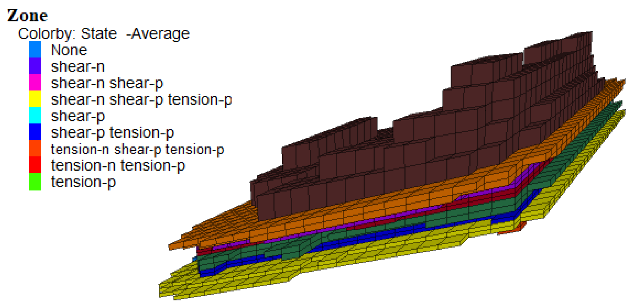
3.1. Principle of FLAC3D Numerical Simulation

FLAC3D uses a discrete hybrid method, so its calculations are performed on a tetrahedron. The finite-difference approximation process of derivatives in computation is illustrated by a tetrahedron. Let the nodes of the tetrahedron be numbered from 1 to 4, and the nth face denotes the face opposite to node n. Assuming that the rate component at any point within it is vi, Equation (1) can be obtained from the Gaussian formula [52,53]
v i , j d V = v i n j d S
where v—volume of the tetrahedron, S—external surface of the tetrahedron, and nj—unit normal vector component of the outer surface.
The forces and masses of FLAC3D software are concentrated on the nodes of the tetrahedron, which are used as the object of calculation and then solved in the time domain by the equations of motion. The equations of motion of the nodes can be expressed as [52,53]:
v i l t = F i l t m l
where F i l t —the unbalanced force component of l-node in the i-direction at time t, which can be deduced by the principle of virtual work, and m l —the concentrated mass of the i-node, which is used to ensure numerical stability when analyzing the static problem with virtual mass, and the actual concentrated mass when analyzing the dynamic problem. In this study, Morh–Coulomb’s large deformation model is used for the solution, and the simulation process is shown below (Figure 3).

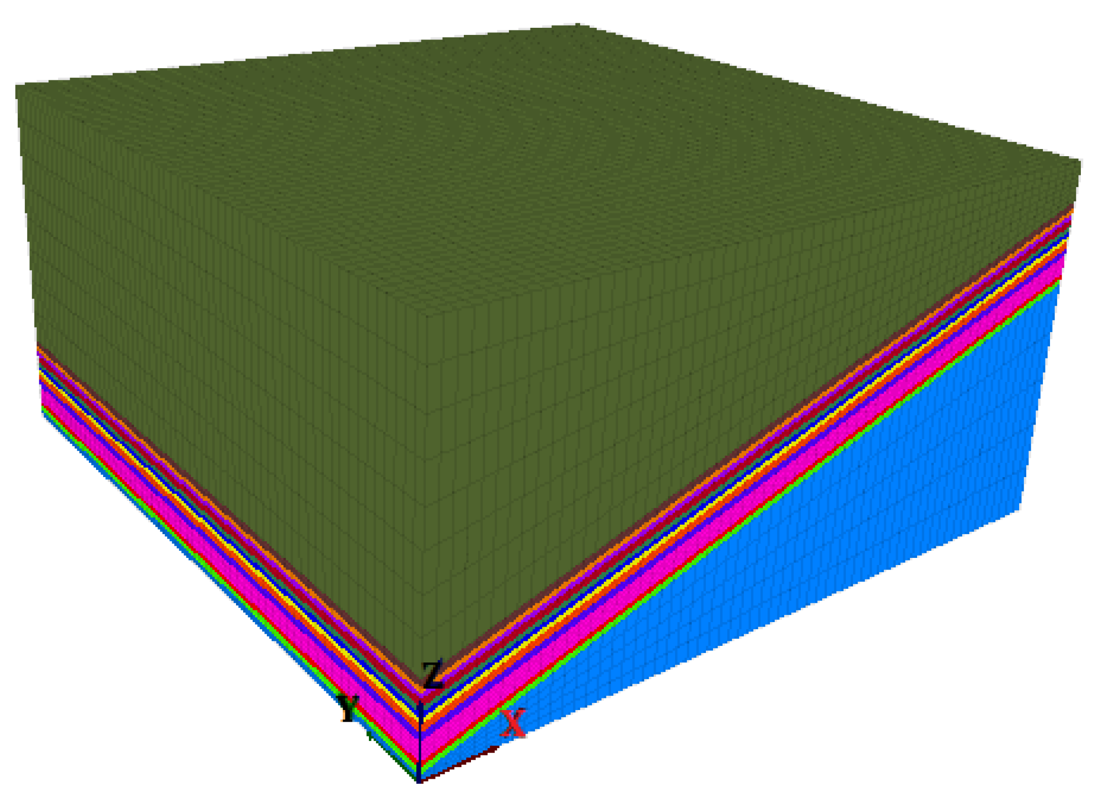
3.2. Numerical Model Settings

Table 1 shows the rock mechanics test parameters and thickness of each rock layer in the study area. The main research objective of this study is the failure of the roof of the No.7 coal seam. A thicker layer of rock is set at the bottom of the model to serve as a substrate. There are 11 rock layers, including coal seams, in the model, with a size of 600 m × 600 m × 300 m (Figure 4). In addition, the mesh of the adjacent No.7 coal roof plate is encrypted to ensure the accuracy of the simulation, and the edges of the model are fixed or constrained. In addition, this numerical model is set up with a scale of 1:1.
In the model schematic, the rock mechanics parameters of each rock layer are assigned from top to bottom, as shown in the table above. It is worth noting that this mining range is set inside the model in order to eliminate the calculation errors caused by boundary effects. The actual mining size of this model is 180 m wide, 250 m long, and 4 m thick.

3.3. Method of Calculating the Capacity of Underground Water Reservoirs in Coal Mines

According to incomplete statistics, there are five popular analytical methods for calculating the capacity of underground water reservoirs in coal mines [1,38,54,55,56]. These methods calculate the capacity of underground water reservoirs in coal mines from different aspects. However, there are still some shortcomings to be overcome. These methods all require the water level in the underground reservoir to be measured before the storage capacity can be calculated, making the storage capacity unpredictable if the water level is unknown. Safety State Administration of Work [54] and Wang et al. [55] only consider rocks in the caving zone as part of the storage capacity, which is unreasonable. Therefore, it is necessary to explore a new method to calculate the reservoir capacity based on numerical simulation.
In this study, we optimized the calculation method for determining the underground water storage space in coal mines. We proposed Formula (3) (Figure 5), which considers the porosity resulting from the residual rock hulking coefficient, as well as the relationship between the rock crush expansion coefficient and the water storage coefficient:
Vs = Vf × (KP’ − 1) × k
where k—the water storage coefficient after failure, k = (KP − 1)/KP, Vs—the storage capacity, Vf—damage volume, KP’—the hulking residual coefficient of rock, and KP—the hulking coefficient of rock.
We use the FISH language to identify the damaged volume (Vf) generated by the numerical simulation. The identification process involves traversing individual cells in the model to determine whether they are in a damaged state. If a cell is found to be broken, the volume of the damaged cell is added to a running total. If not, the algorithm moves on to the next cell until all cells have been traversed.
In addition, to verify whether the simulation results are reasonable, the damage range is measured using a parallel electrical detection technique team [57]. The principle of the parallel electrical method is to equip each electrode with an A/D converter on the basis of a high-density electrical method so that each motor becomes an intelligent electrode that realizes automatic sampling [58,59,60,61]. The electrodes maintain real-time contact with the host computer through a network protocol and send voltage data and current data back to the host computer in real-time through a communication line. Then, we process the data into a simple image profile. Such image data can provide us with an interpretation of the rock damage in the study area.
The resistivity of a rock formation increases when it is damaged and becomes discontinuous. Consequently, a higher resistivity value indicates greater damage to the formation. The horizontal and vertical axes in the figure represent length and height, respectively, in meters. Initially, the overall rock formation shows low resistance, although some areas on the right side exhibit high resistance values. When the roof of the mining area is damaged, the apparent resistivity is higher in the heavily damaged areas. The damage at the bottom gradually extends upwards (as shown in Figure 6).

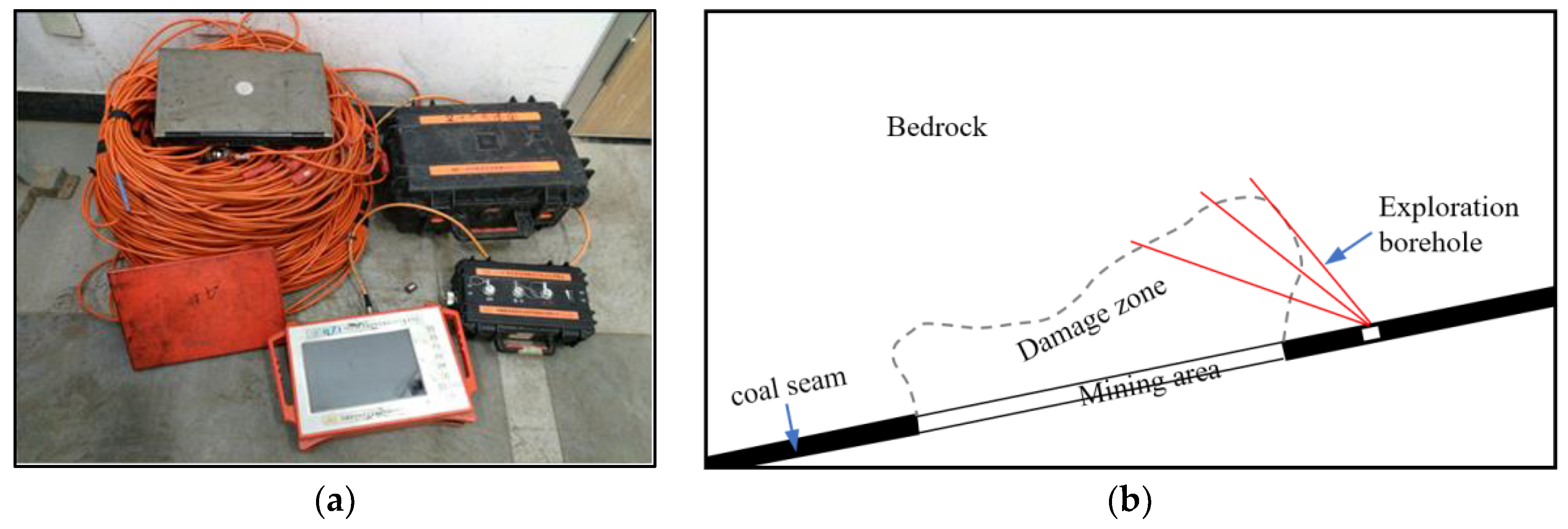
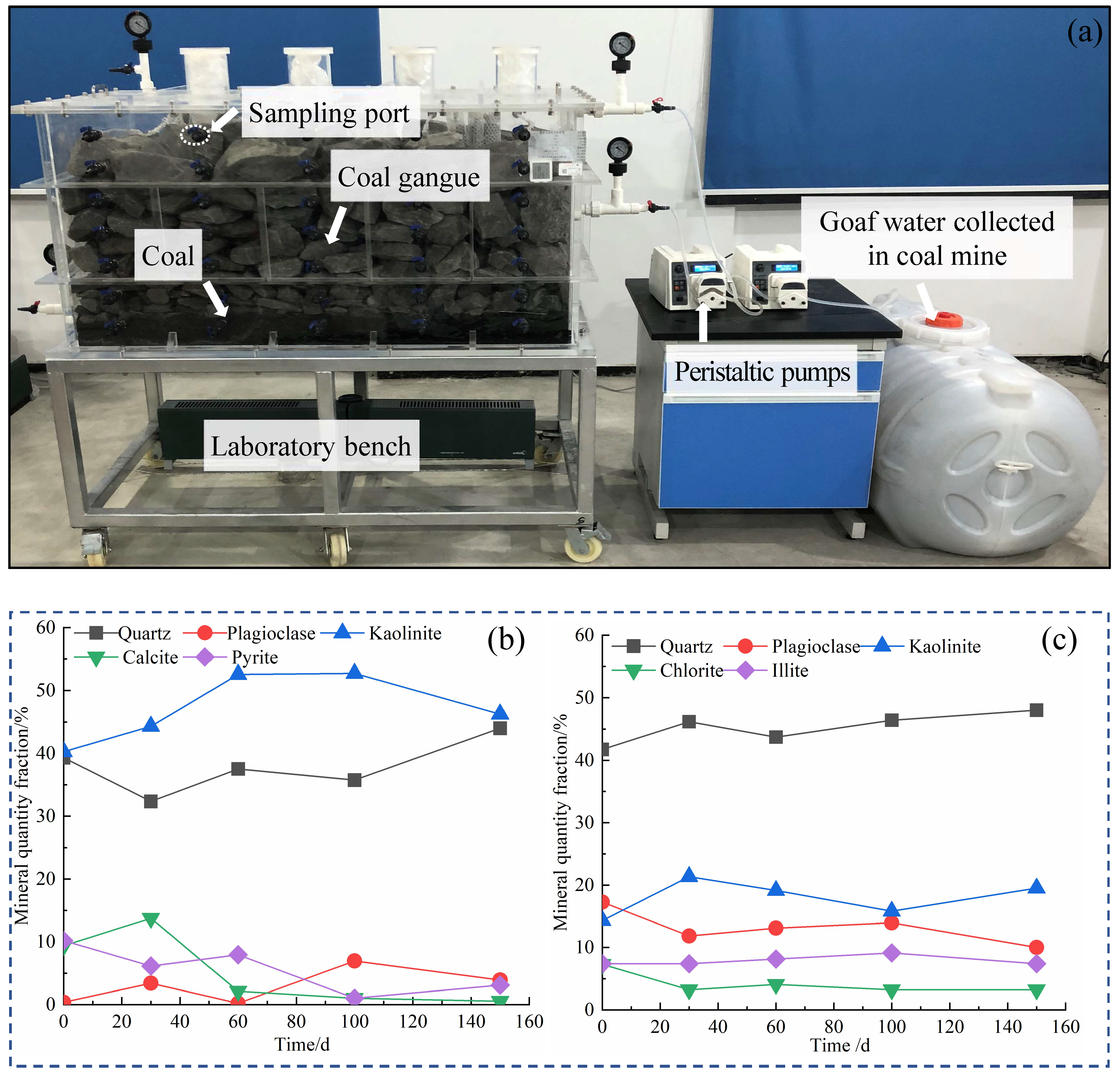
3.4. Water Quality Testing

The contents of Na+, Ca2+, Mg2+, K+, and NH4+ in the water samples during the test were determined using a Varian ICP-OES 720 inductively coupled plasma emission spectrometer. The content of Cl, F, NO3 and SO42− in the water samples was determined by Metrohm IC 925 ion chromatography. Free CO2 and HCO3/CO32− were measured in the laboratory within 48 h after sampling using alkali titration and acid titration, respectively. Water samples of conventional indicators pH, turbidity, dissolved oxygen, redox potential, TDS and other conventional water quality indicators using the Hanna HI98195 Multifunctional Multi-Parameter Water Quality Tester.

4. Results and Discussion

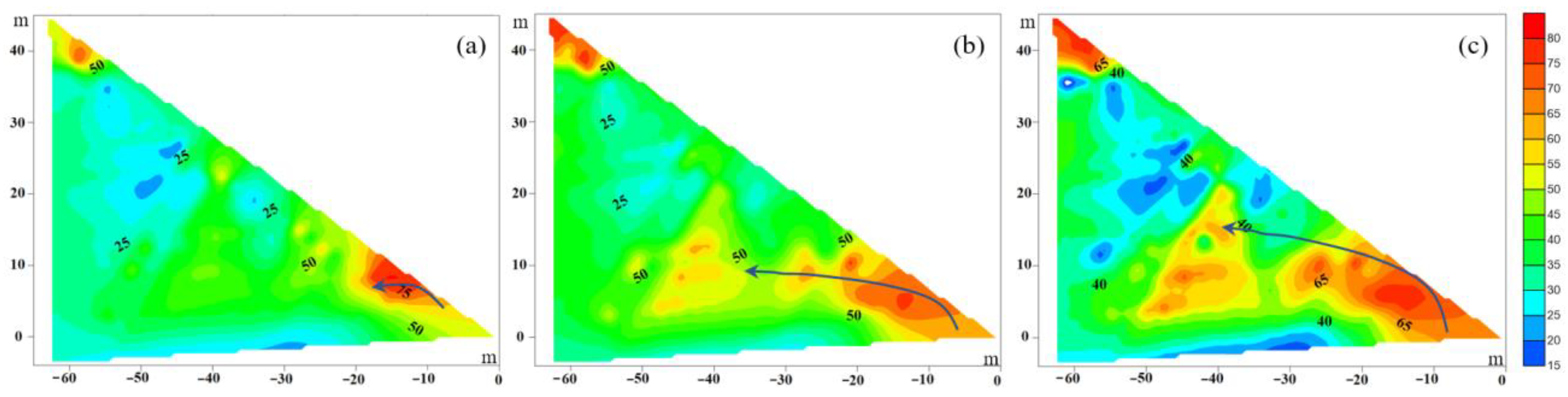
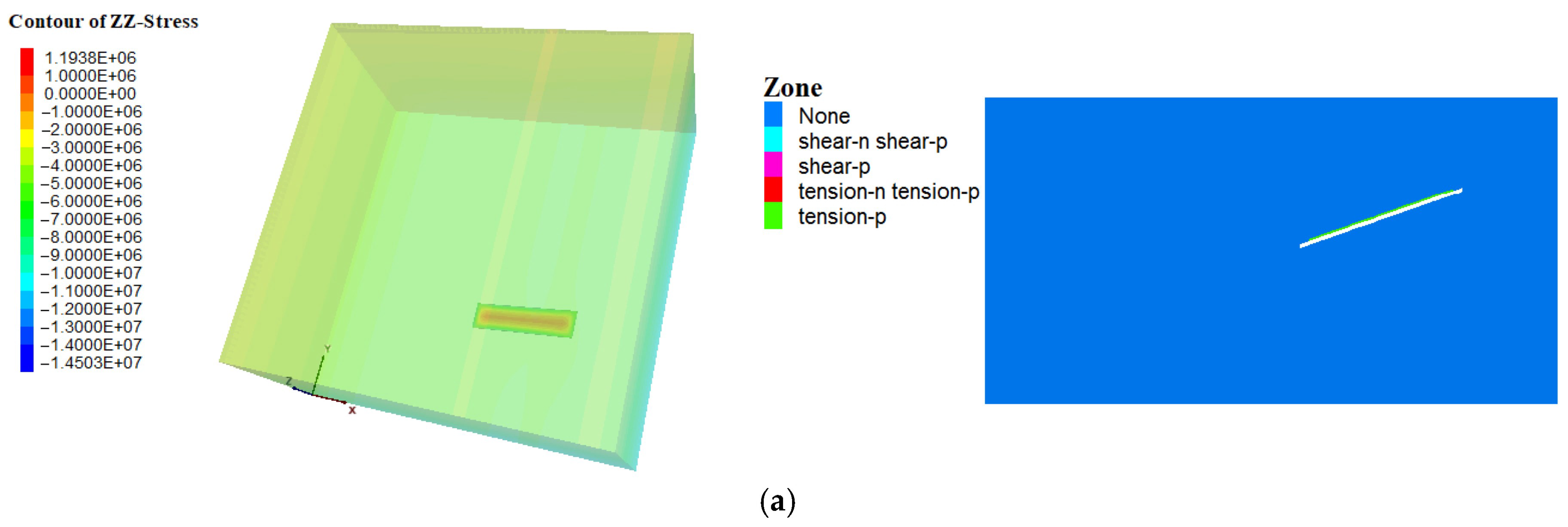
4.1. Analysis of Water Storage Location

According to z-stress (Figure 7 left) and plastic damage (Figure 7 right), the coal seam roof gradually deforms and destroys with the increase of mining area. According to the method described in Section 3.3, it is possible to obtain the damage volume for each mining step. Due to the inclination of the rock stratum, plastic failure began to appear in the upper right area of the coal seam roof when the excavation distance was 30 m, and the damage volume was about 9.89 × 10⁵ m3. When the excavation distance reached 50 m, the damage volume increased to 1.03 × 10⁶ m3. This phenomenon is because the roof strength of the mined-out area cannot resist the overlying compressive stress, which leads to significant instability and damage to the rock stratum. Subsequently, the failure height increases regularly stepwise with the excavation distance. When the excavation reaches 250 m, the damaged height of the top of the No.7 coal seam is about 43.5 m, and the damaged volume is 3.39 × 10⁶ m3.
The testing equipment used in our research area includes one centralized parallel electro-method test system collector, one parallel electro-method collection mainframe, one power converter, three sets of cables dedicated to dielectric electro-method signals, one server, 160 m of cables, and several measuring electrodes (Figure 8a). These devices can help us quickly measure the extent of damage in the study area.
The arrangement of the detection equipment is shown in Figure 8b. The red line represents the monitoring borehole, with evenly distributed monitoring electrodes in the borehole with an interval of two meters. When the rock layer is disturbed, the resistivity will change, and the electrical detection technology can monitor the potential change of the surrounding rock layer in real-time to obtain the damage scope of the mined-out area. The field monitoring period is 45 days, with three soundings per day and an eight-hour interval between each monitoring session. Eventually, the rock 40 m below the coal seam roof is damaged. This finding is consistent with the numerical simulation results, which indicates the reliability of the simulation.
Based on the above results, it is evident that the damaged area of the coal seam roof gradually increases with the expansion of the mining area. The inclined seam causes stress to concentrate on the right side of the model, resulting in a “gentle slope” shape with greater damage in the upper right corner than on the left side. By extracting the damaged cells, a clear three-dimensional shape of the underground coal mine reservoir can be seen (Figure 9). The morphology indicates that the damage range of the mining surface is higher on the right and left sides compared to the middle. The analysis suggests that this is due to the overall sinking of the middle area after the rupture of both sides of the mining face and is not caused by a large-scale rupture of the rock layer. As the numerical model is set at a 1:1 ratio with the actual situation, it is easy to map the simulated water storage location to its actual geographical location. This advantage of 1:1 modeling helps to identify the specific location of underground water storage in coal mines, which is beneficial for future engineering construction of groundwater resource regulation. Based on these findings, the best location for water extraction can be quickly determined on both sides of the mining face, greatly facilitating the implementation of water extraction projects.

4.2. The Storage Capacity of Underground Water Reservoirs in Coal Mines

The damage volume Vf is obtained in Section 4.1 as 3.39 × 10⁶ m3. Miao et al. (1997) [62] and Qian et al. (2010) [63] reported the principles of the rock’s crush coefficient KP and the residual crush coefficient KP′ with respect to rocks. After testing, we obtained KP = 1.65 and KP′ = 1.15. By taking the value of KP, KP′ and Vf into Formula (3), the storage capacity of the underground reservoir in the coal mine after excavation is estimated to be 1.98 × 10⁵ m3. We compared the calculated results with the other two methods, as shown in Figure 5. It is apparent that the other methods yield either excessively small or large results. However, our improved approach, coupled with numerical simulation, produces more reasonable outcomes. Furthermore, we found that the storage capacity of the underground coal mine reservoir increases with the excavation distance after the first damage. This relationship can provide a reference for studying the coal mine underground reservoirs in other areas, which can be expressed as:
y = 49,056.44 + 255.75x + 1.46x2 (R2 = 0.995) (x ≠ 0)
where y is the water storage capacity (m3), x is the excavation distance (m), and R2 is the correlation coefficient. However, a special case needs to be stated, when x is equal to 0, y is 0. In addition, this model is only applicable to mining thicknesses below four meters.

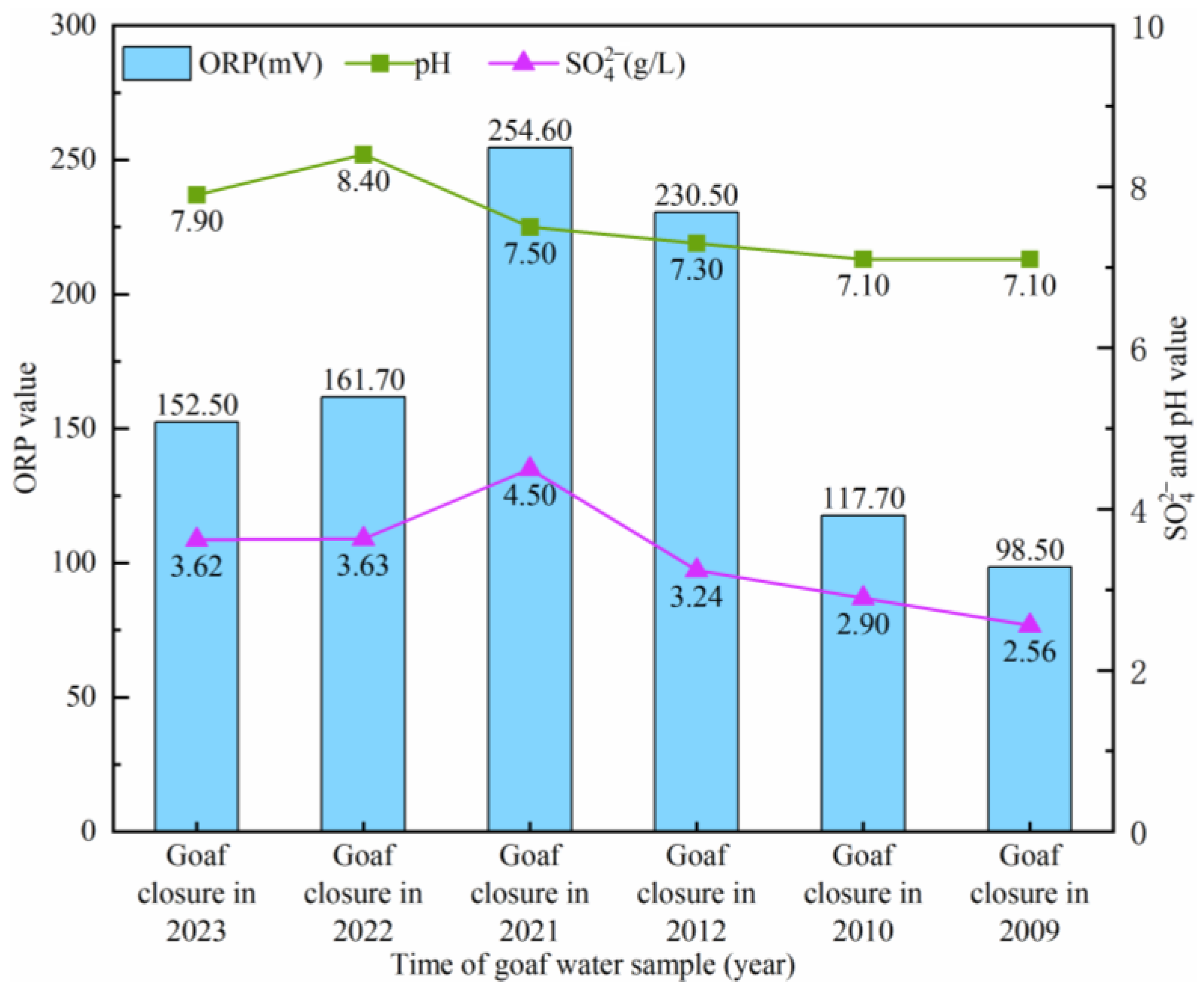
4.3. Water Quality Changes in Underground Water Reservoirs of Coal Mines

Previously, it was believed that mine water quality would worsen with the length of time it remained in the mine. To investigate the factors that influence mine water variation, we conducted a laboratory model test, as shown in Figure 10a. Figure 10b,c illustrate the changes in coal and gangue mineral fractions. The water samples, coal gangue and coal inside the experimental bench were taken from the original location of the coal mine. Notably, the relative contents of stable minerals such as kaolinite and quartz increased compared to their initial levels. On the other hand, the content of calcite and pyrite in coal decreased significantly from 9.8% and 10.2% to 0.6% and 3.1%, respectively. In the gangue rock mass, plagioclase, rhodochrosite, and chlorite showed a decreasing trend, particularly in the first 30 days of the experiment. Similarly, the relative content of plagioclase, potassium feldspar, rhodochrosite, and chlorite in the collapsed rock showed a decreasing trend in the initial 30 days of the test, while other mineral components changed less. Given the realistic test conditions and limitations of our testing instruments, the test period in this study was relatively short, and the model scale was small. Therefore, we collected data on the water quality of goaf water over the past decade.
Limitations on the number of materials received, we chose three factors that are particularly sensitive to change: sulfate ion, pH, and redox potential for the purpose of our research (all ion data are in the Supplementary Information provided). The sulfate ions, redox potential and pH in the old void water show an increasing trend when the water is just formed in the mining area. With the time since goaf closure, the oxygen condition and the degree of water-rock interaction changed, possibly resulting in the change of the hydrochemical characteristics. Figure 11 shows that the concentrations of SO42− (4.5–2.6 g/L) decreased by 42% with the closure of the mining area, and pH also gradually converged to neutral. The trends in redox potential are highly consistent with those of SO42− and pH. Changes in mine water quality occur across all ions in a coherent manner rather than in isolation.
Through the above analysis, it is known that the gangue, which is rich in carbon and has a loose structure, has a strong filtering and purifying effect on water. The sewage can be naturally purified after a long slow flow in the gangue seam. In addition to the occurrence of water-rock reactions, the weak water exchange between mine water and the surrounding aquifers and the action of microorganisms will also lead to a gradual improvement of water quality [64]. Moreover, Donovan et al. (2003) [65] reported similar findings, with SO42− concentrations in water pumped from underground acidic coal mines decreasing significantly after 4 to 18 years. All studies mentioned above suggest that long-term closure has a self-purification effect. We consider that it takes a long time to achieve the purification of mine water. There are also potential negative impacts associated with unpurified reusing mine water. Mine water can contain elevated levels of contaminants, including heavy metals and other toxic substances, which can pose a risk to human health and the environment. Reusing contaminated mine water can lead to the accumulation of these contaminants in soil and water bodies, which can have long-term impacts on the ecosystem. In order to mitigate the potential negative impacts of reusing mine water, several measures can be taken: (1) Mine water should be treated to remove contaminants by physical, chemical, or biological processes, depending on the specific contaminants present in the water before it is reused. (2) Regular monitoring of the quality of the reused mine water is essential to ensure that it does not pose a risk to human health or the environment. (3) It is important to control the rate and timing of water reuse, minimize the area of land that is irrigated with reused water, and implement measures to prevent the accumulation of contaminants in soil and water bodies.

5. Conclusions

In this study, the optimization methods of rock fragmentation and water storage rate are considered to analyze the water storage capacity of an underground water reservoir in a coal mine. Additionally, the simulation allowed us to identify the optimal location for water storage, which can inform future regulation and engineering decisions. The relationship between the storage capacity of underground coal mine reservoirs and the extent of mining is obtained by numerical simulation as y = 49,056.44 + 255.75x + 1.46x2 (R2 = 0.995) (x ≠ 0). The strong relationship between the storage capacity of underground coal mine reservoirs and the extent of mining can provide a basis for the construction of underground coal mine reservoirs in other areas. Therefore, this study can be used as a new method to analyze the underground water reservoir storage in coal mines. Furthermore, the study’s findings indicate that mine water has a self-purification ability, as shown by the significant reduction in sulfate ions and neutralization of pH values. This discovery highlights the potential for reusing the mine water.
Due to the limitations of the study conditions, the results obtained from the current experiments are applicable to mining thicknesses below four meters. The analysis of water quality conditions in the laboratory may be less accurate than actual field experiments, and the evolution of water quality is itself a long-term study. Despite the limitations of the above factors, with the continuous mining of coal resources, the construction of underground water reservoirs in coal mines is a key step for mining companies to achieve green production, protect groundwater resources, and promote water recycling. Therefore, a new, simple and highly accurate method of water storage capacity analysis is needed. The numerical simulation-based water storage capacity analysis shows good potential for application: exactly what is needed. We also hope to receive more funding in the future to invest more effort and time in this area.

Supplementary Materials

The following supporting information can be downloaded at: https://www.mdpi.com/article/10.3390/w15081468/s1, Table S1: Major chemical constituents of water samples in different zones of Coal Mine.

Author Contributions

Conceptualization, C.Z. and Y.S.; formal analysis, Z.X.; funding acquisition, B.L. and Z.X.; investigation, C.Z., B.L. and L.F.; methodology, C.Z., Z.X. and Y.S.; resources, Y.S.; writing—original draft, C.Z. All authors have read and agreed to the published version of the manuscript.

Funding

This research is supported by the National Natural Science Foundation of China (No. 41772245). Natural Science Basic Research Program of Shanxi (No. 20210302124438).

Data Availability Statement

The datasets used and/or analyzed during the current study are available from the corresponding author upon reasonable request.

Acknowledgments

The authors are grateful to the anonymous reviewers for their helpful comments on the manuscript.

Conflicts of Interest

The authors declare no conflict of interest.

References

  1. Gu, D. Theory framework and technological system of coal mine underground reservoir. J. China Coal Soc. 2015, 40, 239–246. [Google Scholar] [CrossRef]
  2. Gu, D.; Zhang, Y.; Cao, Z. Technical progress of water resource protection and utilization by coal mining in China. Coal Sci. Technol. 2016, 44, 1–7. [Google Scholar] [CrossRef]
  3. Sun, Y.; Zhang, L.; Xu, Z.; Chen, G.; Zhao, X.; Li, X.; Gao, Y.; Zhang, S.; Zhu, L. Multi-field action mechanism and research progress of coal mine water quality formation and evolution. J. China Coal Soc. 2022, 47, 423–437. [Google Scholar] [CrossRef]
  4. Yuan, S.; Sui, W.; Han, G.; Duan, W. An Optimized Combination of Mine Water Control, Treatment, Utilization, and Reinjection for Environmentally Sustainable Mining: A Case Study. Mine Water Environ. 2022, 41, 828–839. [Google Scholar] [CrossRef]
  5. Ma, J.; Zhang, G.; Zhou, G.; Zhang, Y.; Meng, X.; Zhao, Y.; Chen, M. Stability analysis of artificial dam in coal mine underground water reservoir based on the hydro-mechanical damage model. Geomat. Nat. Hazards Risk 2023, 14, 2190855. [Google Scholar] [CrossRef]
  6. Wang, X.; Sun, Y.; Xu, Z.; Zheng, J.; Zhang, C. Feasibility prediction analysis of groundwater reservoir construction based on GMS and Monte Carlo analyses: A case study from the Dadougou Coal Mine, Shanxi Province, China. Arab. J. Geosci. 2019, 13, 18. [Google Scholar] [CrossRef]
  7. Kong, X.; Xu, Z.; Shan, R.; Liu, S.; Xiao, S. Investigation on groove depth of artificial dam of underground reservoir in coal mines. Environ. Earth Sci. 2021, 80, 214. [Google Scholar] [CrossRef]
  8. Chen, Y.; Tang, L.; Zhu, S. Comprehensive study on identification of water inrush sources from deep mining roadway. Environ. Sci. Pollut. Res. 2022, 29, 19608–19623. [Google Scholar] [CrossRef] [PubMed]
  9. Zhang, S.; Wang, H.; He, X.; Guo, S.; Xia, Y.; Zhou, Y.; Liu, K.; Yang, S. Research progress, problems and prospects of mine water treatment technology and resource utilization in China. Crit. Rev. Environ. Sci. Technol. 2020, 50, 331–383. [Google Scholar] [CrossRef]
  10. Zhang, C.; Jia, S.; Wu, S.; Liu, J.; Jiao, Y.; Zhang, C. Research status and prospect of underground space utilization mode and key technology in goaf based on underground reservoir. Sci. Technol. Rev. 2021, 39, 36–46. [Google Scholar]
  11. Zhang, C.; Wang, F.; Bai, Q. Underground space utilization of coalmines in China: A review of underground water reservoir construction. Tunn. Undergr. Space Technol. 2021, 107, 103657. [Google Scholar] [CrossRef]
  12. Gu, D.; Li, J.; Cao, Z.; Wu, B.; Jiang, B.; Yang, Y.; Yang, J.; Chen, Y. Technology and engineering development strategy of water protection and utilization of coal mine in China. J. China Coal Soc. 2021, 46, 3079–3089. [Google Scholar] [CrossRef]
  13. Zhang, K.; Gao, J.; Jiang, B.; Han, J.; Chen, M. Experimental study on the mechanism of water-rock interaction in the coal mine underground reservoir. J. China Coal Soc. 2019, 44, 3760–3772. [Google Scholar] [CrossRef]
  14. Zhang, H.; Xu, G. Research on caving structure and water filling characteristic of goaf. Coal Geol. Explor. 2018, 46, 99–102. [Google Scholar]
  15. Zhang, K.; Deng, X.; Gao, J.; Liu, S.; Wang, F.; Han, J. Insight into the Process and Mechanism of Water–Rock Interaction in Underground Coal Mine Reservoirs Based on Indoor Static Simulation Experiments. ACS Omega 2022, 7, 36387–36402. [Google Scholar] [CrossRef] [PubMed]
  16. Xie, H.; Hou, Z.; Gao, F.; Zhou, L.; Gao, Y. A new technology of pumped-storage power in underground coal mine: Principles, present situation and future. J. China Coal Soc. 2015, 40, 965–972. [Google Scholar] [CrossRef]
  17. Pujades, E.; Willems, T.; Bodeux, S.; Orban, P.; Dassargues, A. Underground pumped storage hydroelectricity using abandoned works (deep mines or open pits) and the impact on groundwater flow. Hydrogeol. J. 2016, 24, 1531–1546. [Google Scholar] [CrossRef] [Green Version]
  18. Kitsikoudis, V.; Archambeau, P.; Dewals, B.; Pujades, E.; Orban, P.; Dassargues, A.; Pirotton, M.; Erpicum, S. Underground Pumped-Storage Hydropower (UPSH) at the Martelange Mine (Belgium): Underground Reservoir Hydraulics. Energies 2020, 13, 3512. [Google Scholar] [CrossRef]
  19. Pujades, E.; Orban, P.; Archambeau, P.; Kitsikoudis, V.; Erpicum, S.; Dassargues, A. Underground Pumped-Storage Hydropower (UPSH) at the Martelange Mine (Belgium): Interactions with Groundwater Flow. Energies 2020, 13, 2353. [Google Scholar] [CrossRef]
  20. Pujades, E.; Poulain, A.; Orban, P.; Goderniaux, P.; Dassargues, A. The Impact of Hydrogeological Features on the Performance of Underground Pumped-Storage Hydropower (UPSH). Appl. Sci. 2021, 11, 1760. [Google Scholar] [CrossRef]
  21. Pujades, E.; Orban, P.; Archambeau, P.; Erpicum, S.; Dassargues, A. Numerical study of the Martelange mine to be used as underground reservoir for constructing an Underground Pumped Storage Hydropower plant. Adv. Geosci. 2018, 45, 51–56. [Google Scholar] [CrossRef] [Green Version]
  22. Menéndez, J.; Schmidt, F.; Konietzky, H.; Fernández-Oro, J.M.; Galdo, M.; Loredo, J.; Díaz-Aguado, M.B. Stability analysis of the underground infrastructure for pumped storage hydropower plants in closed coal mines. Tunn. Undergr. Space Technol. 2019, 94, 103117. [Google Scholar] [CrossRef]
  23. Menéndez, J.; Fernández-Oro, J.M.; Galdo, M.; Loredo, J. Pumped-storage hydropower plants with underground reservoir: Influence of air pressure on the efficiency of the Francis turbine and energy production. Renew. Energy 2019, 143, 1427–1438. [Google Scholar] [CrossRef]
  24. Sun, Y.; Chen, G.; Xu, Z.; Yuan, H.; Zhang, Y.; Zhou, L.; Wang, X.; Zhang, C.; Zheng, J. Research progress of water environment, treatment and utilization in coal mining areas of China. J. China Coal Soc. 2020, 45, 304–316. [Google Scholar] [CrossRef]
  25. Pu, H.; Bian, Z.; Zhang, J.; Xu, J. Research on a reuse mode of geothermal resources in abandoned coal mines. J. China Coal Soc. 2021, 46, 677–687. [Google Scholar] [CrossRef]
  26. Edwards, P. Mine Water and the Environment in Wales. Mine Water Environ. 2021, 40, 813–814. [Google Scholar] [CrossRef]
  27. Jiang, B.; Gao, J.; Du, K.; Deng, X.; Zhang, K. Insight into the water–rock interaction process and purification mechanism of mine water in underground reservoir of Daliuta coal mine in China. Environ. Sci. Pollut. Res. 2022, 29, 28538–28551. [Google Scholar] [CrossRef]
  28. Li, J.; Huang, Y.; Li, W.; Guo, Y.; Ouyang, S.; Cao, G. Study on dynamic adsorption characteristics of broken coal gangue to heavy metal ions under leaching condition and its cleaner mechanism to mine water. J. Clean. Prod. 2021, 329, 129756. [Google Scholar] [CrossRef]
  29. Zhang, K.; Gao, J.; Men, D.; Zhao, X.; Wu, S. Insight into the heavy metal binding properties of dissolved organic matter in mine water affected by water-rock interaction of coal seam goaf. Chemosphere 2021, 265, 129134. [Google Scholar] [CrossRef] [PubMed]
  30. Zhao, L.; Zhang, Y.; Du, C.; Jiang, B.; Wei, L.; Li, Y. Characterization of dissolved organic matter derived from coal gangue packed in underground reservoirs of coal mines using fluorescence and absorbance spectroscopy. Environ. Sci. Pollut. Res. 2021, 28, 17928–17941. [Google Scholar] [CrossRef]
  31. Jiang, B.-b.; Ji, K.-m.; Xu, D.-j.; Cao, Z.-g.; Wen, S.-k.; Song, K.; Ma, L. Effects of Coal Gangue on the Hydrochemical Components under Different Types of Site Karst Water in Closed Mines. Water 2022, 14, 3110. [Google Scholar] [CrossRef]
  32. Liang, Z.; Gao, Q.; Wu, Z.; Gao, H. Removal and kinetics of cadmium and copper ion adsorption in aqueous solution by zeolite NaX synthesized from coal gangue. Environ. Sci. Pollut. Res. 2022, 29, 84651–84660. [Google Scholar] [CrossRef] [PubMed]
  33. Jin, Y.; Liu, Z.; Han, L.; Zhang, Y.; Li, L.; Zhu, S.; Li, Z.P.J.; Wang, D. Synthesis of coal-analcime composite from coal gangue and its adsorption performance on heavy metal ions. J. Hazard. Mater. 2022, 423, 127027. [Google Scholar] [CrossRef]
  34. Li, Q.; Ju, J.; Cao, Z.; Gao, F.; Li, J. Suitability evaluation of underground reservoir technology based on the discriminant of the height of water conduction fracture zone. J. China Coal Soc. 2017, 42, 2116–2124. [Google Scholar] [CrossRef]
  35. Pummer, E.; Schüttrumpf, H. Reflection Phenomena in Underground Pumped Storage Reservoirs. Water 2018, 10, 504. [Google Scholar] [CrossRef] [Green Version]
  36. Song, H.Q.; Xu, J.J.; Fang, J.; Cao, Z.G.; Yang, L.Z.; Li, T.X. Potential for mine water disposal in coal seam goaf: Investigation of storage coefficients in the Shendong mining area. J. Clean. Prod. 2020, 244, 118646. [Google Scholar] [CrossRef]
  37. Wang, F.; Wei, X.; Shao, D.; Zhang, C. The progressive failure mechanism for coal pillars under the coupling of mining stress and water immersion in underground reservoirs. Bull. Eng. Geol. Environ. 2023, 82, 103. [Google Scholar] [CrossRef]
  38. Ju, J.; Xu, J.; Zhu, W. Storage capacity of underground reservoir in the Chinese western water-short coalfield. J. China Coal Soc. 2017, 42, 381–387. [Google Scholar] [CrossRef]
  39. Pang, Y.; Li, Q.; Cao, G.; Zhou, B. Analysis and calculation method of underground reservoir water storage space composition. J. China Coal Soc. 2019, 44, 557–566. [Google Scholar] [CrossRef]
  40. Rudakov, D.; Westermann, S. Analytical modeling of mine water rebound: Three case studies in closed hard-coal mines in Germany. Min. Miner. Depos. 2021, 15, 22–30. [Google Scholar] [CrossRef]
  41. Chi, M.; Cao, Z.; Li, Q.; Zhang, Y.; Wu, B.; Zhang, B.; Yang, Y.; Liu, X. Water Supply and Regulation of Underground Reservoir in Coal Mine considering Coal-Water Occurrence Relationship. Geofluids 2022, 2022, 2892964. [Google Scholar] [CrossRef]
  42. Wang, B.F.; Xing, J.C.; Liang, B.; Zhang, J. Experimental study on deformation characteristics of rock and coal under stress-fluid interactions in coal mine underground water reservoir. Energy Sources Part A Recovery Util. Environ. Eff. 2020. [Google Scholar] [CrossRef]
  43. González-Quirós, A.; Fernández-Álvarez, J.P. Conceptualization and finite element groundwater flow modeling of a flooded underground mine reservoir in the Asturian Coal Basin, Spain. J. Hydrol. 2019, 578, 124036. [Google Scholar] [CrossRef]
  44. Menéndez, J.; Loredo, J.; Galdo, M.; Fernández-Oro, J.M. Energy storage in underground coal mines in NW Spain: Assessment of an underground lower water reservoir and preliminary energy balance. Renew. Energy 2019, 134, 1381–1391. [Google Scholar] [CrossRef]
  45. Bader, M.; Mehl, M.; Rude, U.; Wellein, G. Simulation software for supercomputers. J. Comput. Sci. 2011, 2, 93–94. [Google Scholar] [CrossRef]
  46. Hariri-Ardebili, M.A.; Furgani, L.; Salamon, J.; Rezakhani, R.; Xu, J. Numerical simulation of large-scale structural systems. Adv. Mech. Eng. 2019, 11. [Google Scholar] [CrossRef] [Green Version]
  47. Liu, J.Q.; Zhao, J.X.; Liu, Q.H.; Su, A.J.; Zhang, Q.H.; Zhang, S.; Wang, Z.L.; Wang, Z.H. Integration and application of 3D visualization technology and numerical simulation technology in geological research. Environ. Earth Sci. 2021, 80, 776. [Google Scholar] [CrossRef]
  48. Chi, M.; Li, Q.; Cao, Z.; Fang, J.; Wu, B.; Zhang, Y.; Wei, S.; Liu, X.; Yang, Y. Evaluation of water resources carrying capacity in ecologically fragile mining areas under the influence of underground reservoirs in coal mines. J. Clean. Prod. 2022, 379, 134449. [Google Scholar] [CrossRef]
  49. Xu, Z.; Sun, Y.; Gao, S.; Zhang, C.; Bi, Y.; Chen, Z.; Wu, J. Law of mining induced water conduction fissure in arid mining area and its significance in water-preserved coal mining. J. China Coal Soc. 2019, 44, 767–776. [Google Scholar] [CrossRef]
  50. Zhang, Y.; Zhang, Z. Research progress of mining overlying stratas failure law and control technology. Coal Sci. Technol. 2020, 48, 85–97. [Google Scholar] [CrossRef]
  51. Liu, Q.; Sun, Y.J.; Xu, Z.M.; Jiang, S.; Zhang, P.; Yang, B.B. Assessment of Abandoned Coal Mines as Urban Reservoirs. Mine Water Environ. 2019, 38, 215–225. [Google Scholar] [CrossRef]
  52. Nagtegaal, J.C.; Parks, D.M.; Rice, J. On Numerically Accurate Finite Element Solutions in the Fully Plastic Range. Comp. Meth. Appl. Mech. Eng. 1974, 4, 153–177. [Google Scholar] [CrossRef]
  53. Bathe, K.J.; Wilson, E.L. Numerical Methods in Finite Element Analysis; Prentice-Hall Inc.: Englewood Cliffs, NJ, USA, 1976. [Google Scholar]
  54. Wang, B.F.; Liang, B.; Wang, J.G.; Sun, K.M.; Sun, W.J.; Chi, H.B. Experiment study on rock bulking of coal mine underground reservoir. Rock Soil Mech. 2018, 39, 4086. [Google Scholar] [CrossRef]
  55. Safety State Administration of Work. Coal Mine Safety Regulation; China Coal Industry Publishing House: Beijing, China, 2011. [Google Scholar]
  56. Shi, X. Research progress and prospect of underground mines in coal mines. Coal Sci. Technol. 2022, 1–10. Available online: https://kns.cnki.net/kcms/detail/11.2402.TD.20210429.1746.002.html (accessed on 30 April 2021).
  57. Lu, T.; Liu, S.D.; Wang, B.; Wu, R.X.; Hu, X.W. A Review of Geophysical Exploration Technology for Mine Water Disaster in China: Applications and Trends. Mine Water Environ. 2017, 36, 331–340. [Google Scholar] [CrossRef]
  58. Wu, R.; Zhang, P.; Liu, S. Exploration of two-gateway network parallel electrical technology for exploring thin-coal area within coal face. Chin. J. Rock Mech. Eng. 2009, 28, 1834–1838. [Google Scholar]
  59. Wu, R.; Zhang, W.; Zhang, P. Exploration of parallel electrical technology for the dynamic variation of caving zone strata in coal face. J. China Coal Soc. 2012, 37, 571–577. [Google Scholar] [CrossRef]
  60. Liu, B.; Guo, C.; Yang, H. Research on the integrated electric exploration system for coal mines and its application. Coal Geol. Explor. 2021, 49, 247–252. [Google Scholar]
  61. Su, B.Y.; Liu, S.D.; Deng, L.; Gardoni, P.; Krolczyk, G.M.; Li, Z.X. Monitoring Direct Current Resistivity During Coal Mining Process for Underground Water Detection: An Experimental Case Study. IEEE Trans. Geosci. Remote Sens. 2022, 60, 5915308. [Google Scholar] [CrossRef]
  62. Miao, X.; Mao, X.; Hu, G. Research on broken expend and express and press solid characteristics of rocks and coals. J. Exp. Mech. 1997, 3, 64–70. [Google Scholar]
  63. Qian, M.; Shi, P.; Xu, J. Ground Pressure and Strata Control; China University of Mining and Technology Press: Xuzhou, China, 2010. [Google Scholar]
  64. Zhang, L.; Xu, Z.; Sun, Y.; Gao, Y.; Zhu, L. Coal Mining Activities Driving the Changes in Microbial Community and Hydrochemical Characteristics of Underground Mine Water. Int. J. Environ. Res. Public Health 2022, 19, 13359. [Google Scholar] [CrossRef] [PubMed]
  65. Donovan, J.J.; Leavitt, B.R.; Werner, E. Long-term changes in water chemistry as a result of mine flooding in closed mines of the Pittsburgh Coal Basin, USA. In Proceedings of the 6th International Conference on Acid Rock Drainage, Cairns, Australia, 14–17 July 2003; pp. 869–875. [Google Scholar]
Figure 1. Regional tectonic diagram (① Fengfei fault; ② Subei fault; ③ Fengyong fault; ④ Guzhen fault; ⑤ Taihe-Wuhe fault; ⑥ Fuyang deep fault; ⑦ Sunzhuang fault; ⑧ Wain Yellow River fault; ⑨ Shaolou fault; ⑩ Weishanhu lake).
Water 15 01468 g001
Figure 2. Schematic diagram of the main water storage space (wherein: I: Caving Zone; II: Fissure Zone; the light blue area is the main water storage space).
Water 15 01468 g002
Figure 3. Numerical simulation calculation process.
Water 15 01468 g003
Figure 4. Numerical model schematic.
Water 15 01468 g004
Figure 5. Relationship between excavation distance and water storage capacity [54,55].
Water 15 01468 g005
Figure 6. Development monitoring map of the damaged area: (a) damage at the beginning of mining, (b) damage at the middle of mining, and (c) damage at the end of mining.
Water 15 01468 g006
Figure 7. The contour of z-stress (left) and plastic damage profile in the extraction zone (right): (a) excavation 30 m, (b) excavation 50 m, and (c) excavation 250 m.
Water 15 01468 g007aWater 15 01468 g007b
Figure 8. Parallel electric prospecting instrument (a) and monitoring layout schematic (b).
Water 15 01468 g008
Figure 9. Water storage location obtained by numerical simulation.
Water 15 01468 g009
Figure 10. Experimental tests (a) experimental setup; (b) change in mineral mass of coal; (c) change in mineral mass of coal gangue.
Water 15 01468 g010
Figure 11. The change characteristics of mine water ions (the red arrows in the graph indicate the trend of ion changes).
Water 15 01468 g011
Table 1. Rock mechanics parameters for numerical models.
Layer NumberhρKGCφRm
125019600.280.10.85250.35
2526903.352.33.6412.96
3425502.611.353.6362.0
4326702.611.353.6362.0
5 (No.7 Coal seam)414002.080.541.2200.64
6326903.352.33.6412.96
7526503.051.923.1402.8
8426702.611.353.6362.0
9325502.611.353.6363.0
10414002.080.541.2200.64
111526903.352.33.6412.96
Notes: Abbreviations: h—thickness (m); ρ—density (kg/m3); K—Bulk modulus (GPa); G—Shear modulus (GPa); C—Cohesion (MPa); φ—Friction angle (°); Rm—Tensile strength (MPa).
Disclaimer/Publisher’s Note: The statements, opinions and data contained in all publications are solely those of the individual author(s) and contributor(s) and not of MDPI and/or the editor(s). MDPI and/or the editor(s) disclaim responsibility for any injury to people or property resulting from any ideas, methods, instructions or products referred to in the content.

