

Analysis of Flow Characteristics around a Square Cylinder with Boundary Constraint

State Key Laboratory of Hydrology-Water Resources and Hydraulic Engineering, Nanjing Hydraulic Research Institute, Nanjing 210098, China
*
Author to whom correspondence should be addressed.
Water 2023, 15(8), 1507; https://doi.org/10.3390/w15081507
Submission received: 31 January 2023
/
Revised: 20 March 2023
/
Accepted: 10 April 2023
/
Published: 12 April 2023
(This article belongs to the Special Issue Advanced Research on Hydraulic Engineering and Hydrological Modelling)
Abstract
:Based on the two-dimensional hydrodynamic model of the finite volume method and structured multigrid, the flow characteristics around a square cylinder with boundary constraint are analysed. The gap ratio G/D (G is the distance from the cylinder to the channel boundary, and D is the side length of the square cylinder) does not change the four flow patterns. Under the laminar vortex street phase, the boundary constraint only reduces the scale of the vortices. The vortex centres are pressed toward the boundaries of the channel, and a low velocity zone is formed near the boundary, but the law of vorticity attenuation along the flow direction is not changed. The flow pattern classification map shows that the boundary constraint increases the Reynolds number required to generate the turbulence flow pattern, and the range of the Reynolds number in the flow pattern of the laminar vortex street has a maximum increase range. The correlation between the time-averaged drag coefficient or the vortex shedding frequency and Reynolds number under different gap ratios indicates that the resistance of the square cylinder and the vortex shedding frequency increase accordingly with the strengthening of the boundary constraint. When G/D < 3.5, the increase is particularly obvious. Meanwhile, the correlation characteristics between the resistance or the vortex shedding frequency of the square cylinder and the Reynolds number are unrelated to the boundary constraint strength.
1. Introduction
Flow around a square cylinder is a classic problem in fluid mechanics. When fluids such as air and water flow through square components such as high-rise buildings, bridge piers, and floodgate pillars, they are affected by the cylinder, and flow patterns with different characteristics are produced. The characteristics are related to the Reynolds number of fluids, the shape and size of the cylinder, the space size, etc. The pulsation and resonance effects caused by fluid separation and vortex shedding of the flow around a cylinder can affect the safety of the building itself. Therefore, the complex flow characteristics around a square cylinder have always been a hotspot and a challenge in academic research, and they provide important references for related practical applications.
Flow around a cylinder is a typical phenomenon of the flow around a blunt body. The development of the flow around a cylinder is closely related to the boundary layer of the cylinder. Because of the retarding action of the boundary mutation of the cylinder, the velocity and pressure gradient near the cylinder are obvious. Under large gradients, the thickness of the fluid boundary layer increases and separates from the cylinder boundaries, forming a backflow in the downstream direction of the cylinder. The above process is the origin of the flow around a cylinder. The separation and shedding of the boundary layer, the flow changes of the shear layer, and the flow pattern distribution of the wake are coupled with each other to form a complete flow around a cylinder. The Reynolds number is a key factor in determining the flow pattern around a cylinder. At different Reynolds numbers, the flow around a cylinder exhibits completely different fluid characteristics. According to the flow characteristics under different Reynolds numbers, the flow around a square cylinder can usually be divided into four types of flow pattern classifications, namely L1, L2, L3, and T. The four types of flow pattern classifications and their main characteristics are shown in Table 1 (Williamson, 1988 [1]; Wang, et al., 2001 [2]); Behara and Mittal, 2010 [3]).
A physical model test and numerical simulation are the main methods for the study of the flow around a cylinder. Using a tracer (Coutanceau and Defaye, 1991 [8]), aluminium powder (Taneda, 1956 [4]), soap liquid film (Wu, et al., 2004 [9]; Couder, 1981 [10]; Chomaz, 2001 [11]; Beizaie and Gharib, 1997 [12]), PIV (Kim, et al., 2015 [13]; Palau-Salvador et al., 2010 [14]) and other tools, physical model tests have been widely used to study the flow around a cylinder, but these tests have been limited in terms of their scale effect correction, boundary layer restoration, and measurement accuracy. Compared with the physical model test, the numerical simulation has the characteristics of accurate data extraction, no scaling effect, and low cost. Thus, it is widely used in the study of the flow around a cylinder. However, the mutation of boundaries of the flow around a cylinder, the complexity of the local flow pattern, and the strong turbulence characteristics demand high requirements in terms of the accuracy of the numerical simulation results. Considering the calculation efficiency while improving the calculation accuracy is an important indicator of the excellence of the numerical simulation method of the flow around a cylinder. The turbulence model and grid meshing are the primary methods of optimizing the numerical simulation method of the flow around a cylinder.
To reduce the influence of boundary conditions, the distance between the cylinder and the boundaries is usually increased, or the boundaries are set as slip boundaries during numerical simulation (Sen et al., 2011 [15]; Tong et al., 2022 [16]). However, the influence of boundary conditions on the flow around a cylinder is unavoidable in the real environment. Bridge piers, submarine cables, oil and gas pipelines, radiators, grids etc. are all typical examples of the flow around a cylinder constrained by boundaries (Yang et al., 2021 [17]; Prsic et al., 2016 [18]; Chen and Wu, 2019 [19]). The gap ratio G/D provides a quantitative basis for the constraint degree of the boundaries on the cylinder (Lei, 2000 [20]). According to the size of the gap ratio, the constraint effect of the boundaries on the flow around a cylinder can be subdivided into several stages (Nishino et al., 2007 [21]; Lei et al., 2000 [22]). When the gap is relatively large, for example, when the G/D of the flow around a cylinder is greater than 0.8, the boundaries have no effect on the vortex shedding and the wake flow pattern around a cylinder (Khabbouchi et al., 2013 [23]). As the boundaries of the channel narrow, for example, when the G/D is less than 0.8, the boundary constraint effect begins to increase significantly, and the shedding of the vortices of the flow around a cylinder is inhibited by the boundaries (Prsic et al., 2016 [18]; Durao et al., 1991 [24]). Meanwhile, the separation angle, frequency and vorticity intensity of the resistance, lift intensity, and vortex shedding of the cylinder change with the variation of the G/D (Yang et al., 2021 [18]; Lei et al., 2000 [22]; Khabbouchi et al., 2013 [23]; Martinuzzi et al., 2003 [25]), and the distribution and stability of the wake behind the cylinder are affected (Nishino et al., 2007 [22]; Martinuzzi et al., 2003 [25]; Bailey et al., 2002 [26]; Bearman and Zdravkovich, 1978 [27]; Grass et al., 1983 [28]).
Physical model test tools, such as a wind tunnel or a PIV, can trace the vortex shedding frequency and wake structure of the flow around a cylinder under boundary constraint (Khabbouchi et al., 2013 [23]; Bearman and Zdravkovich, 1978 [27]; Shi et al., 2010 [29]; Zhou et al., 2022 [30]; Price et al., 2002 [31]), but numerical simulation is still required to obtain the exact values of physical quantities such as force conditions. The confinement effect of the boundaries can amplify the local gradient of physical quantities such as velocity and pressure around the cylinder, which demands higher requirements for the error control of the numerical simulation.
The selection of the turbulence model and grid meshing method is closely related to the calculation accuracy of the flow around a cylinder with boundary constraint. Direct numerical simulation (DNS) can accurately restore various fluid characteristics of the flow around a cylinder (Zhang et al., 2020 [32]; Trias et al., 2015 [33]; Dong et al., 2006 [34]), but the high calculation cost constrains the application of DNS in the numerical simulation of the flow around a cylinder with boundary constraint (Behera and Saha, 2019 [35]; Ji et al., 2019 [36]). Large eddy simulation (LES) has been widely used in the numerical simulation of the flow around a cylinder (Rodi et al., 1997 [37]; Voke, 1997 [38]; Kahil et al., 2019 [39]); it has mainly been used to accurately restore the transient flow pattern of the flow around a cylinder because calculation costs are reduced significantly. In the numerical simulation of the flow around a cylinder with boundary constraint, LES can accurately restore the separation angle, the vortex shedding frequency, the resistance, and lift intensity of the cylinder (Prsic et al., 2016 [18]; Rodi, 1997 [40]; Grigoriadis et al., 2003 [41]). The grid resolution is closely related to the simulation accuracy of the flow around a cylinder with boundary constraint. The O-H meshing strategy based on a structured multigrid divides the computational domain of the flow around a cylinder into the high-resolution area near the cylinder and the ordinary resolution area in other areas. This strategy not only accurately restores the fluid characteristics and the wake flow pattern near the cylinder, but also considers the calculation efficiency (Khan and Ibrahim, 2019 [42]) and is the preferred meshing strategy for the numerical simulation of the flow around a cylinder with boundary constraint (Prsic et al., 2016 [18]; Kanaris et al., 2011 [43]).
Unlike cylinders, square cylinders have a discontinuous boundary shape with several right-angle mutations. Different boundary layer separation mechanisms lead to differences in the vortex shedding laws between cylinders and square cylinders (Norberg, 1993 [44]). Among these, abrupt boundaries, such as right angles, can have a significant impact on the flow pattern, especially the generation of vortices. At present, the research on the flow around a cylinder with boundary constraint has mainly used cylinders as the research object (Prsic et al., 2016 [18]; Chen and Wu, 2019 [19]; Khabbouchi et al., 2013 [23]), and there have been few research results related to the flow around a square cylinder (Yang et al., 2021 [17]). However, in practical application, it is impossible for the cylinder to be of an absolutely smooth construction as structures with edge angles widely exist. Meanwhile, the research has mainly focused on the force condition of the cylinder itself and the relationship between the local flow pattern near the cylinder and boundary constraint (Khabbouchi et al., 2013 [23]). There have been few studies on the distribution and development law of the wake of the flow around a cylinder by boundary constraint (Prsic et al., 2016 [18]). The wake of the flow around a cylinder has a wider range of influence and this also has research value.
In this study, a square cylinder was taken as the research object. Based on the finite volume method and a structured multigrid, a two-dimensional mathematical model was established to simulate the flow around a square cylinder with boundary constraint in a rectangular channel. The boundary constraint effect was studied under four flow patterns: laminar, transitional flow pattern, vortex street, and turbulence. The resistance of the cylinder, the vortex shedding frequency caused by the flow around a square cylinder, and the flow pattern of the wake behind the square cylinder are studied, and the mechanism of the boundary constraint interfering with the flow around a square cylinder is discussed.
2. Numerical Simulation Method for Flow around a Square Cylinder
2.1. Mathematical Model
According to the flow characteristics around a square cylinder, a two-dimensional mathematical model was developed. The governing equations were modified as follows:
Here is the fluid density, is the dynamic viscosity, is the velocity vector, is the scalar pressure, is the inertia force, is the cartesian coordinate, and and are the x direction unit vector and the y direction unit vector, respectively.
The finite volume method was used to discretize the governing equation, the quadrilateral multigrid was used to discretize the two-dimensional model, and the PISO calculation method was used to couple the pressure and velocity.
The inlet was set as the velocity inlet boundary with steady velocity, and the outlet was set as the free outflow boundary. A no-slip wall boundary was used for the plane boundary of the model.
For the initial condition, the computational domain was set as a stationary flow field, and each physical quantity was assigned as 0.
The transient model was used for the numerical simulation. The convergence accuracy of each physical quantity was set to .
2.2. Computational Domain and Boundary Conditions
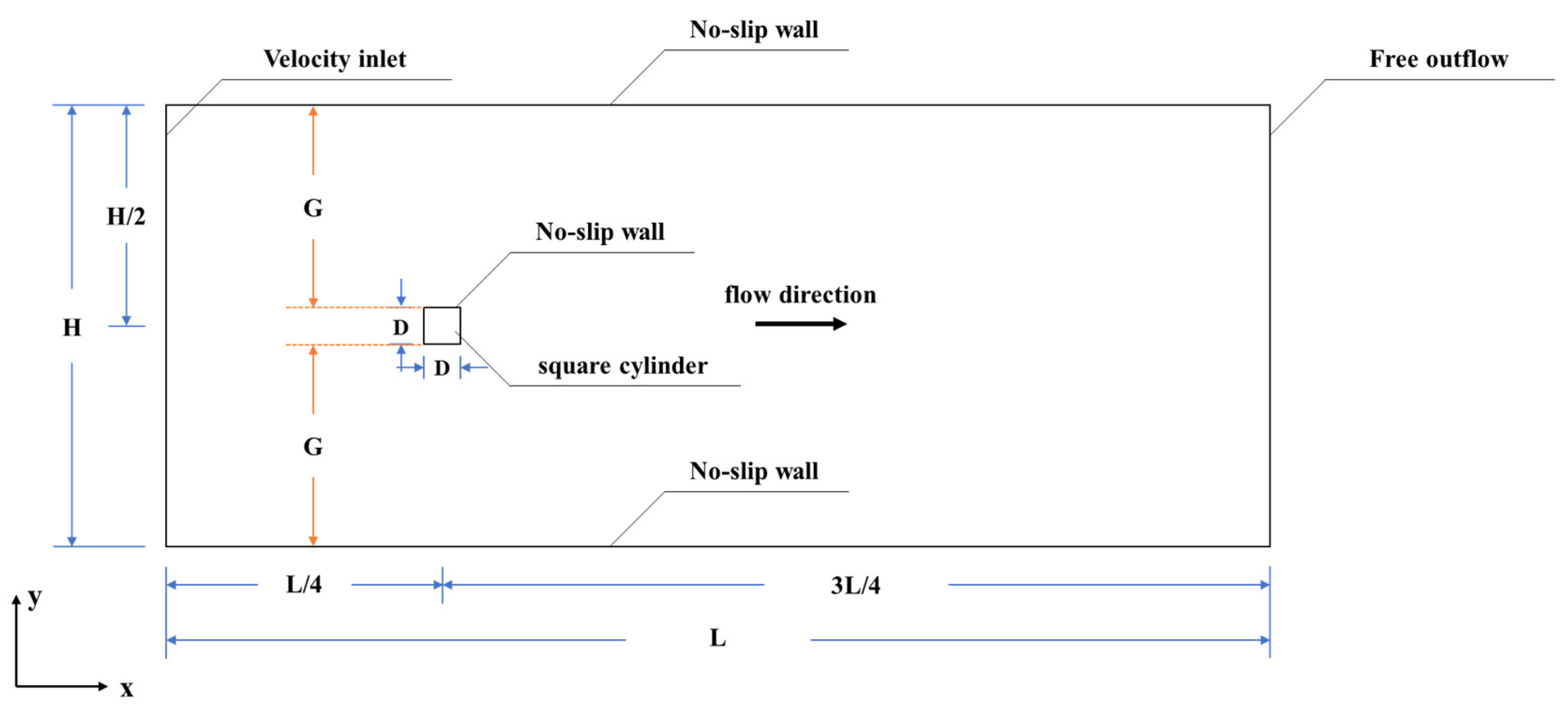
In the actual application scenarios of the flow around a cylinder, such as bridge piers, high-rise buildings, wind turbines, etc., the geometric shapes in the horizontal direction are similar to those in the vertical direction (Blackburn and Henderson, 1999 [45]; Sadeque et al., 2008 [46]; Yuce and Kareem, 2016 [47]; Zaid et al., 2019 [48]), so the characteristics of the flow around a cylinder in the horizontal direction are representative. Meanwhile, the velocity distribution of the approaching flow, such as water flow and wind, are uniform and symmetrical on the scale of the cylinder. Therefore, the computational domain was set as a two-dimensional rectangular channel with length L and width H. The two ends of the channel were the inlet and outlet. A square cylinder with a side length of D was set at the axis of the channel. The distance between the square cylinder and the inlet and outlet of the channel were ¼L and ¾L, respectively. The length L of the computational domain and the side length D of the square cylinder, as well as their positions, were fixed. To keep the flow pattern near a square cylinder free from the influence of the inlet and outlet boundary, it was necessary to keep the cylinder and boundaries at a greater distance. Thus, we set L = 30 D, and the cylinder was ¼L and ¾L from the inlet and outlet boundaries, respectively. The width H of the computational domain can be adjusted in the range of H = 2 D~12 D during the calculation. In this study, D was set to 0.4 m. The flow around a square cylinder was simulated under different Reynolds numbers by adjusting the velocity at the inlet boundary. The schematic diagram of the computational domain and boundary conditions is shown in Figure 1, where x is the flow direction, and y is the width direction of the rectangular channel.
2.3. Computational Grids
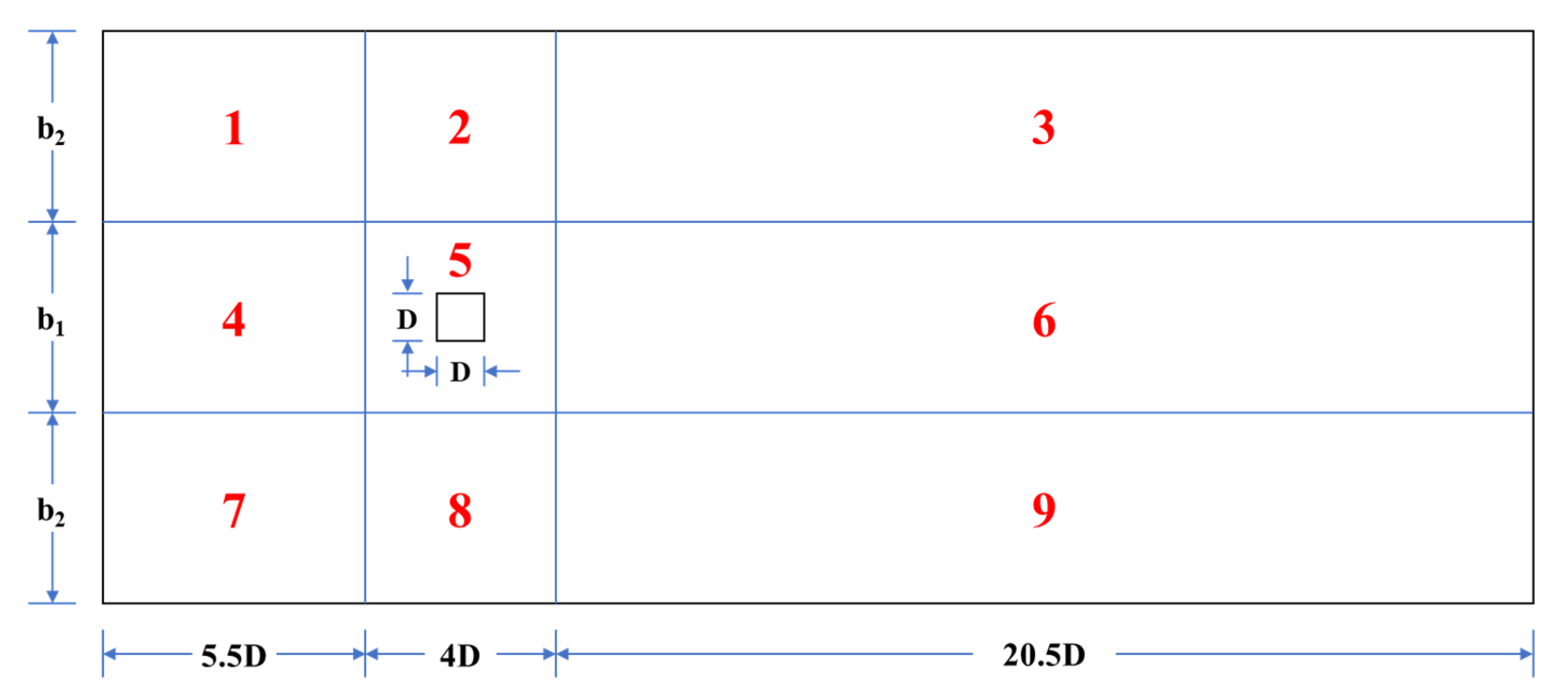
Structured grids were used to fit the rectangular computational domain with square inner boundaries. Different grid sizes were set in different parts of the computational domain. In the area close to the square cylinder, the grid density was relatively high, while in the other area the density was relative. The computational domain was divided into nine zones with different grid sizes. The location of these nine zones is shown in Figure 2.
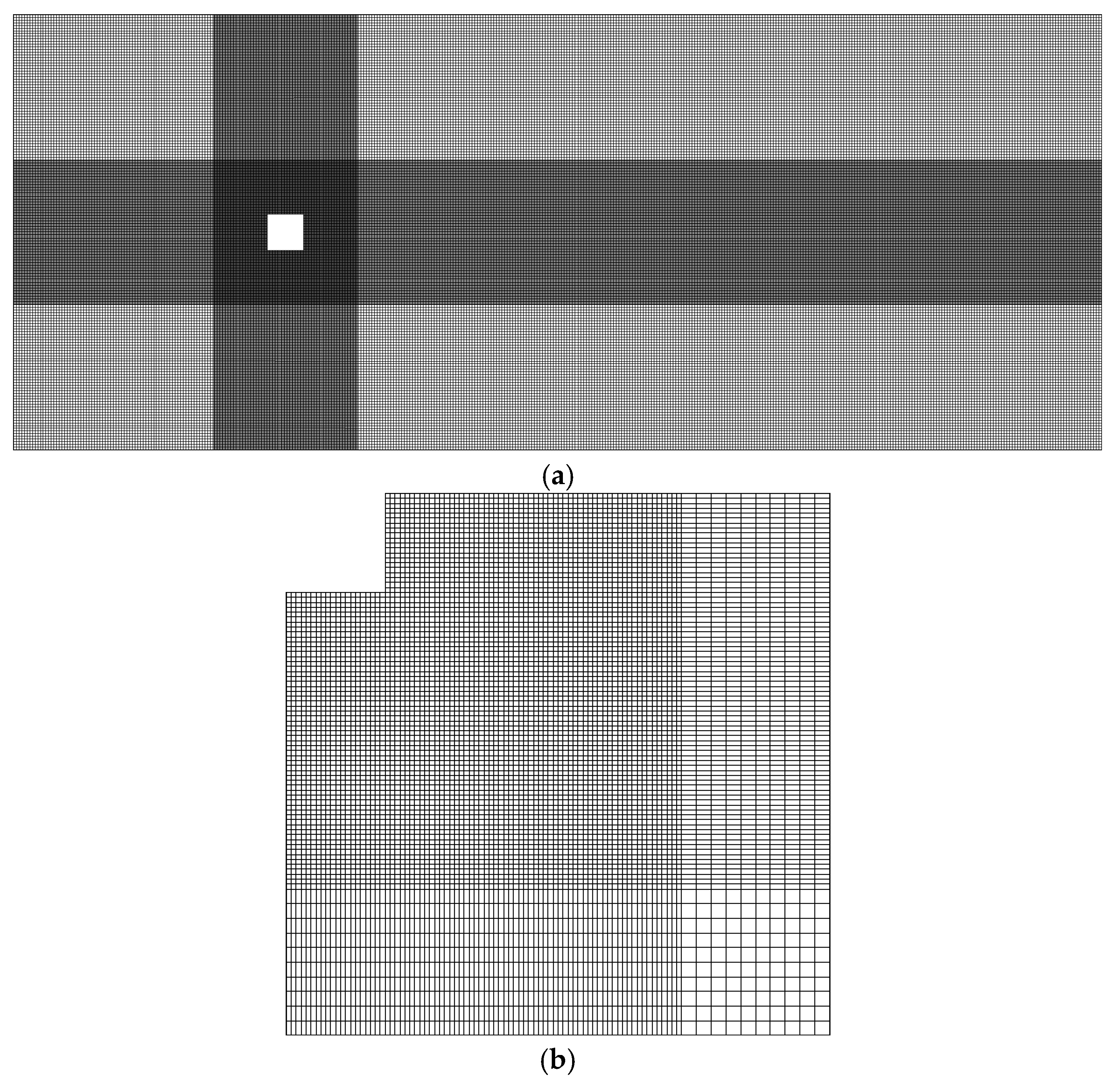
Here, when , and , , only zones 4, 5, and 6 exist. The grid sizes in the nine zones are shown in Table 2, where grid sizes are adjusted by variable . The computational grid distribution of the computational domain is shown in Figure 3.
To optimize the simulation in terms of accuracy and computational cost, the influence of the grid resolution on the simulation results was examined. A specific channel width (H = 12 D) was set, and the simulation results under different grid resolutions were compared. The time-averaged drag coefficient and the Strouhal number were important parameters to describe the fluid characteristics around a square cylinder.
The time-averaged drag coefficient is a dimensionless coefficient that reflects the resistance of a square cylinder in the fluid and is modified as follows:
Here, is the time-averaged drag coefficient, is the resistance of a square cylinder, that is, the pressure difference between the stoss side and slip slope of a square cylinder, is the streamwise velocity, is the side length of the square cylinder and the characteristic length defining the Reynolds number, , is the period that includes a certain variation period of the drag coefficient. The Strouhal number is a dimensionless coefficient describing the periodic unsteady flow, which, in this study, was used to reflect the shedding frequency of the vortex from the flow around a square cylinder.
Here, is the Strouhal number, is the shedding frequency of the vortex from the flow around a square cylinder.
By adjusting the velocity at the inlet boundary, the Reynolds number of the flow around a square cylinder was set. The Reynolds number was modified as follows:
Here is the Reynolds number and is the kinematic viscosity of the fluid.
The flow around a square cylinder under different grid resolutions () was simulated where = 40 and 100, and the results were compared. The time-averaged drag coefficient and the Strouhal number of the flow around a square cylinder under different grid resolutions are shown in Table 3.
It can be seen from Table 3 that, with the increase in the grid density, the simulation results of the flow around a square cylinder tended to converge. When was less than 0.0125, with the further reduction of , the change range of and was very small. When = 40, replacing the grid G5 with the finest grid G6 resulted in only a 0.9% change in . When = 1000, replacing the grid G5 with the finest grid G6 resulted in only a 1.4% change in and 0.2% in . Though grid G6 () provided the finest simulation results, the computational cost of this grid resolution was too high. Grid G5 () was acceptable. Thus, was set to define the grid sizes.
2.4. Model Analysis
A specific channel width (H = 12 D) was selected, the numerical results under different velocity inlet conditions were compared, and the rationality of this calculation model was analysed.
Using the flow around a square cylinder under the conditions of = 40, 200, 1000, and 22,000, the earlier research results were compared with the calculation results in this study. The time-averaged drag coefficient and the Strouhal number of the flow around a square cylinder under different Reynolds numbers between the present and earlier results are compared in Table 4.
It can be seen from Table 4 that when = 40, 200, 1000, and 22,000, both and in this study were in good agreement with the earlier numerical and physical results, indicating that the calculation model established in this study had good effectiveness and accuracy under different values.
3. Characteristics of the Flow around a Square Cylinder under Boundary Constraint
3.1. Feature of Wake Flow Patterns of the Flow around a Square Cylinder
The flow pattern distributions around a square cylinder in the four classifications L1, L2, L3, and T (Table 1) are shown in Figure 4.
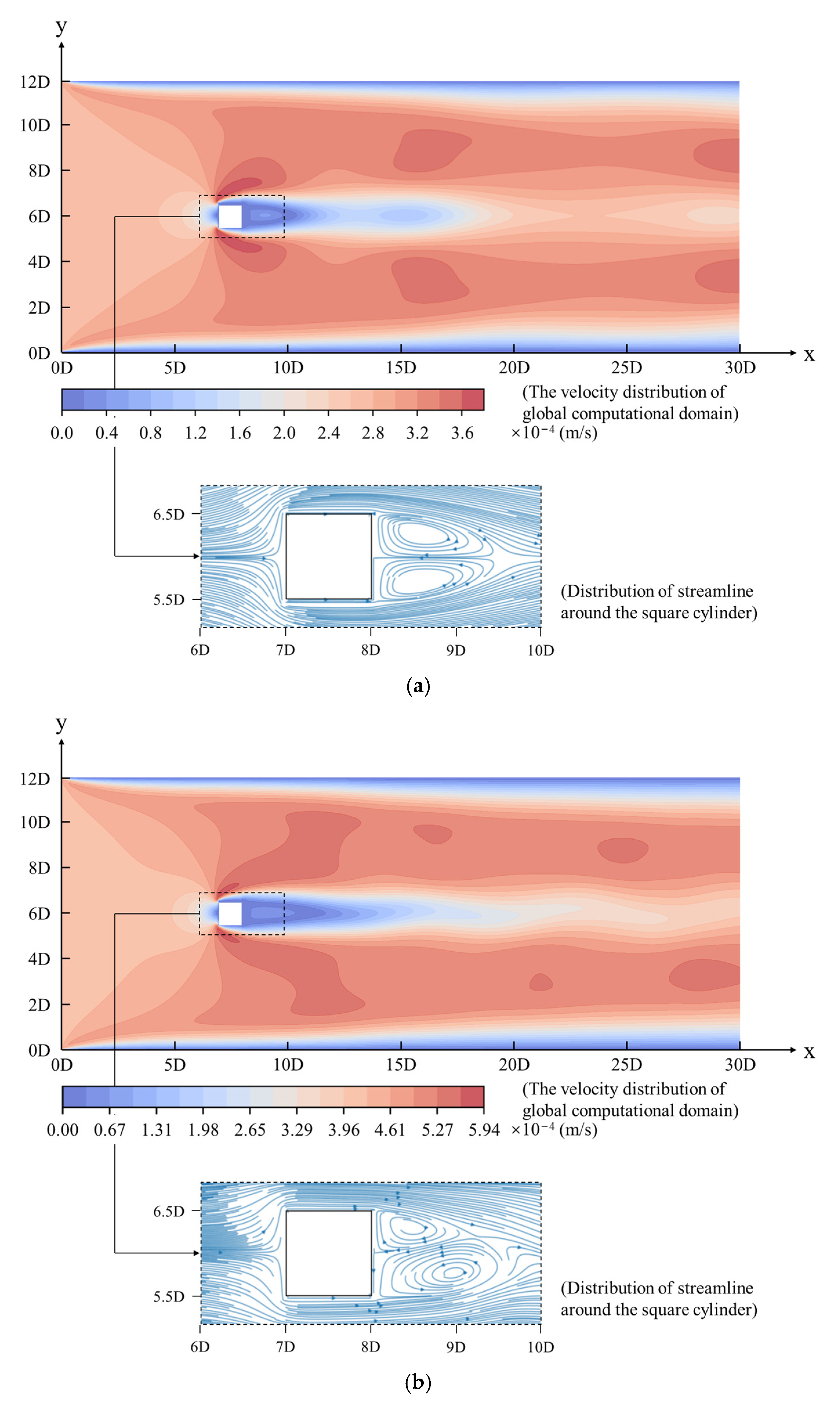
When was low, the flow around a square cylinder formed a closed wake composed of two attached vortices behind the square cylinder (Classification L1, Classification L2), as shown in Figure 4a,b. Here, the positions of the attached vortices were stable, and they did not appear to be shedding from the triangular area behind the square cylinder and moving downstream. The action range of the vortices was limited to the triangular area behind the square cylinder and the flow field in most other areas of the channel was still laminar flow. When exceeded a specific value, the attached vortices behind the square cylinder appeared to be shedding, and the vortices moved freely in the downstream direction (Classifications L3 and T), as shown in Figure 4c,d. Here, the area behind the square cylinder was the area affected by the eddy current, and its action range was much larger than that of Classifications L1 and L2.
3.2. Boundary Constraint Effect in Vortex Street Flow
Under the laminar vortex street flow pattern (Classification L3), the regular shedding of the attached vortices had an impact on the change of the flow pattern within a specific range behind the square cylinder, so Classification L3 was chosen for study. Quantitative research was carried out on the distribution and motion law of the vortices and the influence of the boundary constraint on the wake flow pattern around a square cylinder.
A dimensionless coefficient gap ratio G/D was defined, which characterized the constraint degree of the boundaries to the flow around a square cylinder. G/D was modified as follows:
Here G/D is the gap ratio, H is the width of the rectangular channel, D is the side length of the square cylinder, G is the distance from the side of the square cylinder to the plane boundary of the channel (Figure 2).
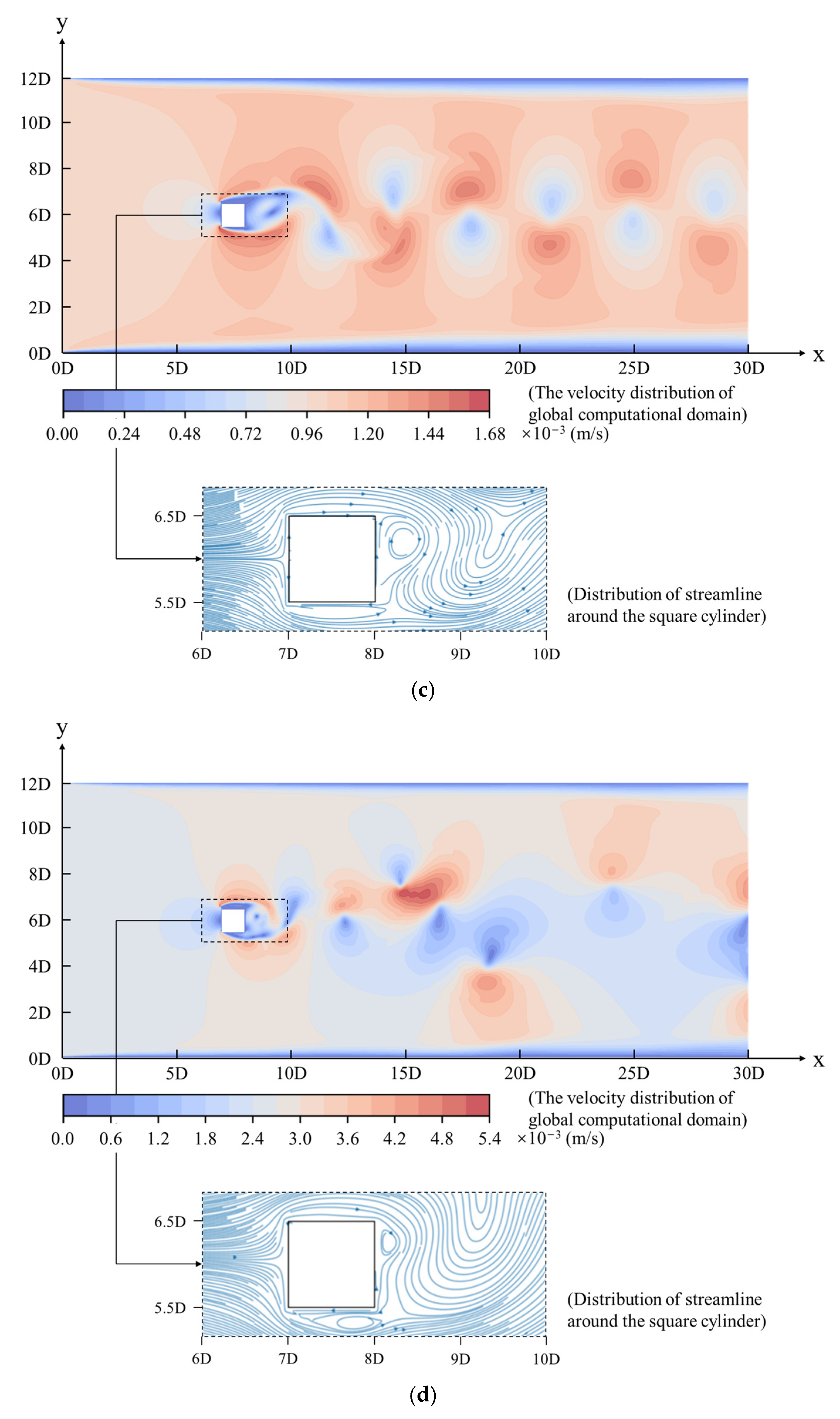
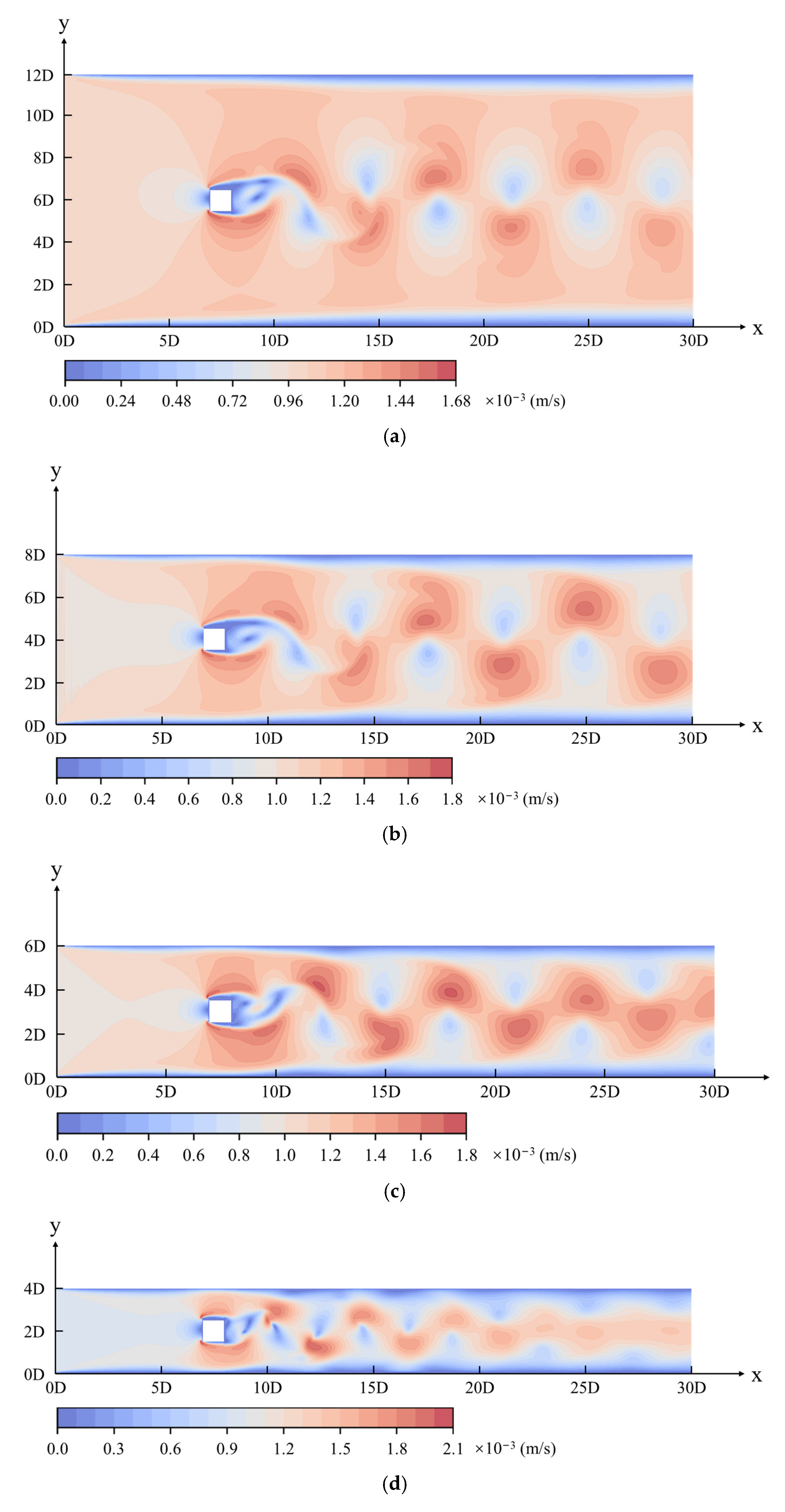
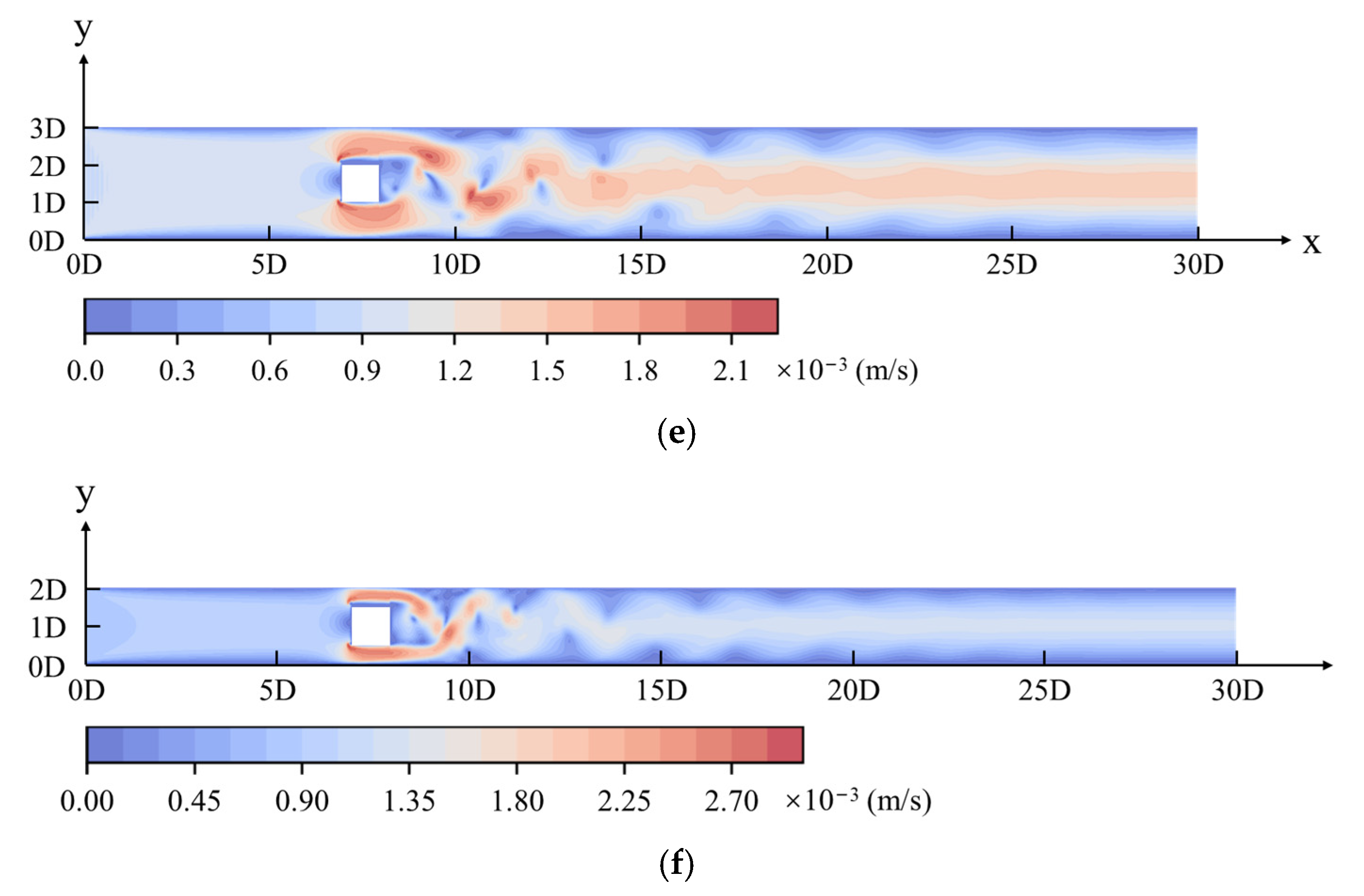
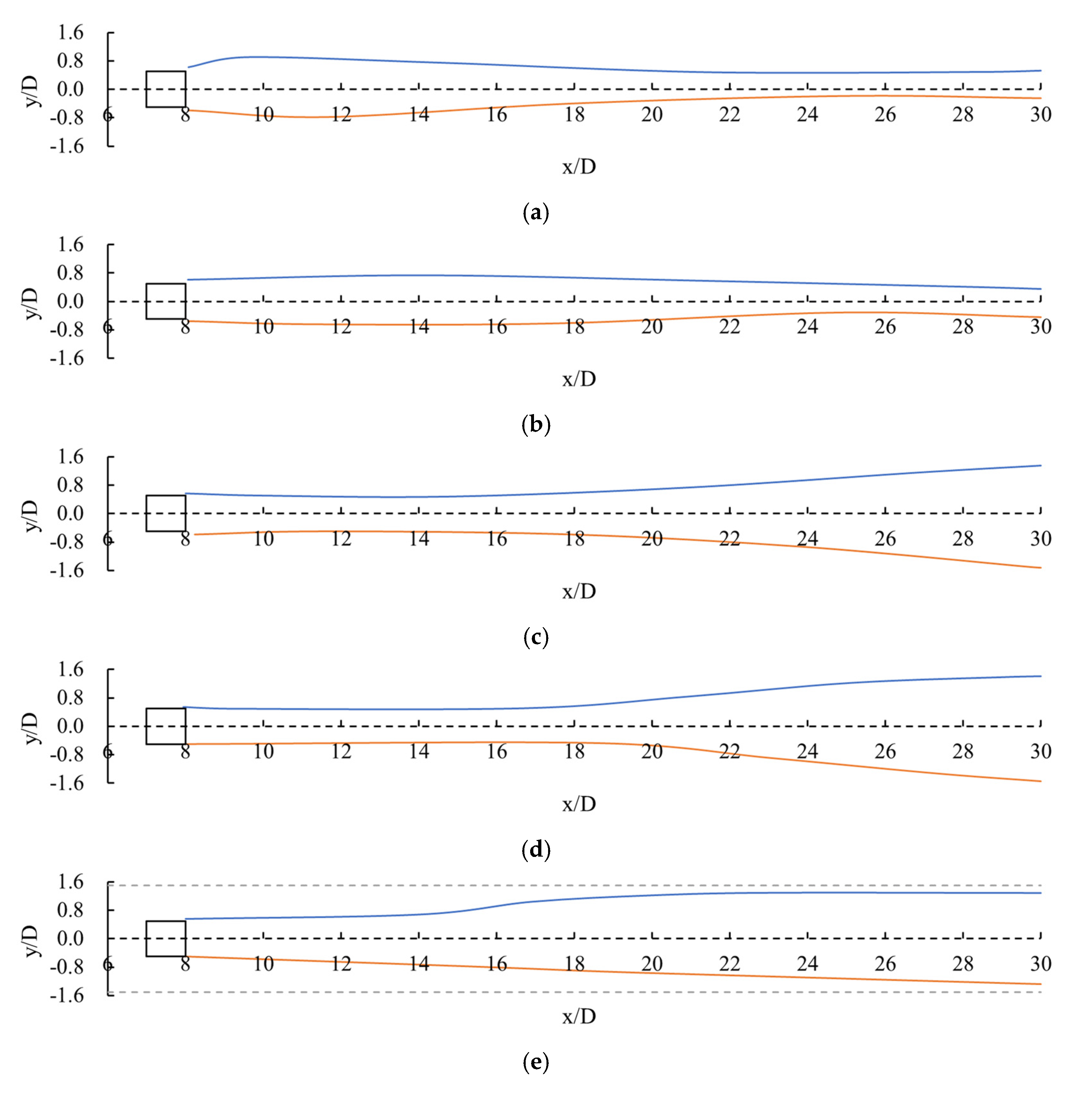
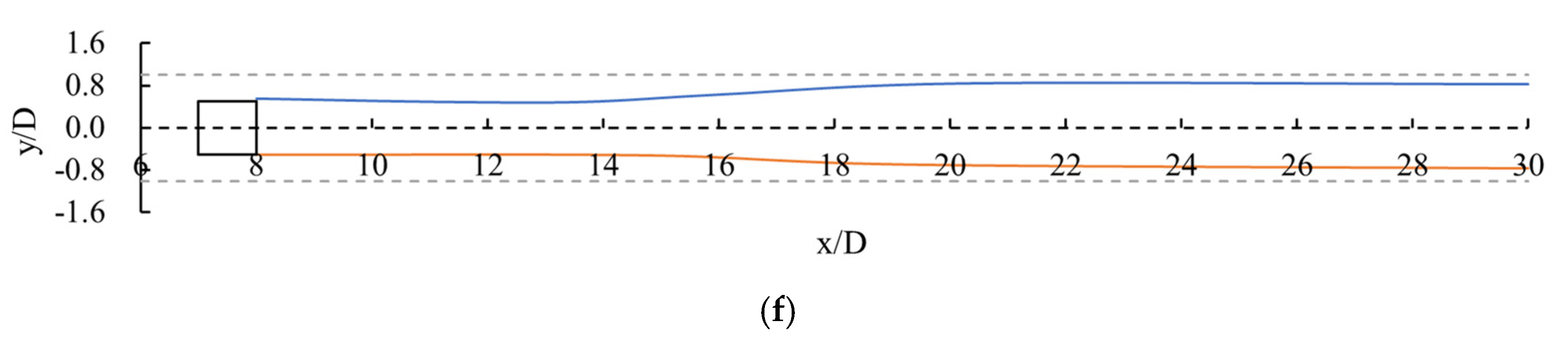
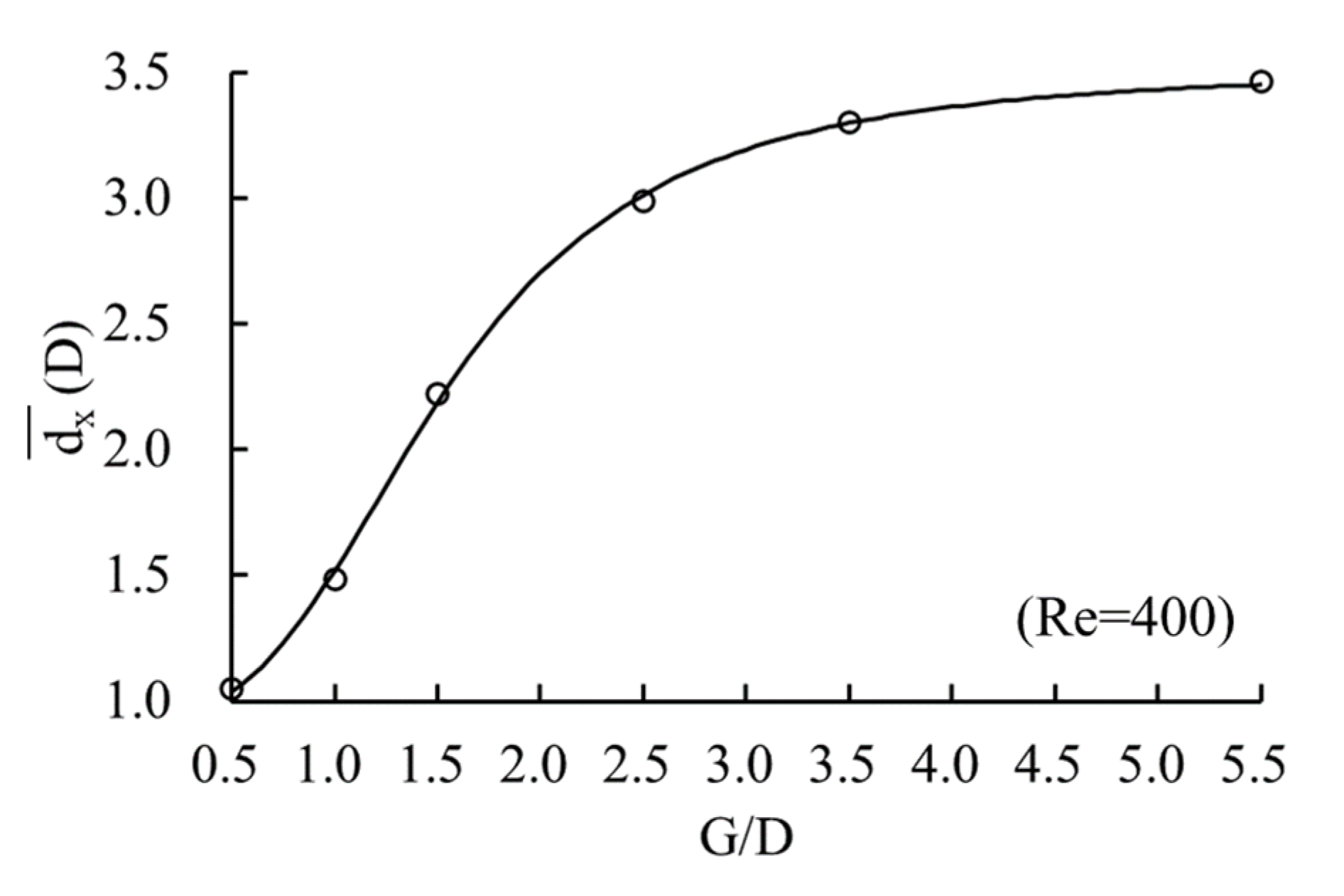
According to Section 2.1, when = 400, the vortex street can form behind the square cylinder. The flow pattern around a square cylinder, the trajectory of the vortex centres, and the average distance of the vortex centres along the flow direction when G/D = 5.5, 3.5, 2.5, 1.5, 1.0, and 0.5 are shown in Figure 5, Figure 6 and Figure 7, respectively.
The constraint degree of the channel boundaries will affect the distribution of the vortex street and the movement of the vortices. When the gap of the channel is large (G/D ≥ 3.5), the flow pattern of the post-cylinder wake is similar, and the constraint degree of boundaries is weak. Here, the two trajectories of the vortex centres were closer to the axis of the channel. When the gap was small (G/D < 3.5), the constraint degree of the boundaries became more obvious, the channel boundaries began to interfere with the shape and distribution of the vortex street, and the degree of interference increased along the flow direction. After extrusion by the constrained boundary, the volume of the vortices decreased, and the two trajectories of the vortex centres gradually migrated to both sides of the channel along the flow direction. As the constraint degree was further enhanced (0.5 < G/D < 2.5), the vortices were extruded by the channel boundaries, and its size was further reduced. The vortex centres moved a certain distance near the axis and then migrated to the two sides of the channel. Then, they reached the channel boundaries and moved downstream along them. A low velocity area was formed near the boundaries. The greater the constraint degree of the boundaries, the more forward the starting point of the trajectory migration of the vortex centres. The constraint effect of the boundaries reduced the distance between adjacent vortices in the wake along the flow direction. When G/D ≥ 3.5, the distance between adjacent vortex centres along the flow direction did not decrease significantly, but when G/D < 3.5, the effect of the boundary constraint was increasingly strengthened, and the amplitude reduction of increased significantly.
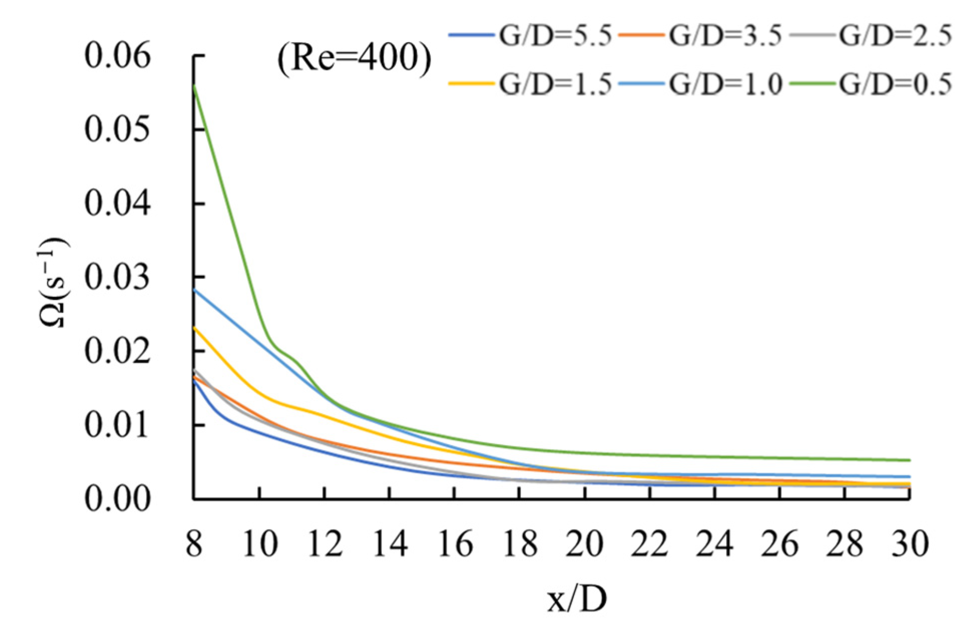
The variation of vortex vorticity along the flow direction with different boundary constraints is shown in Figure 8. was modified as follows:
Here, is vortex vorticity.
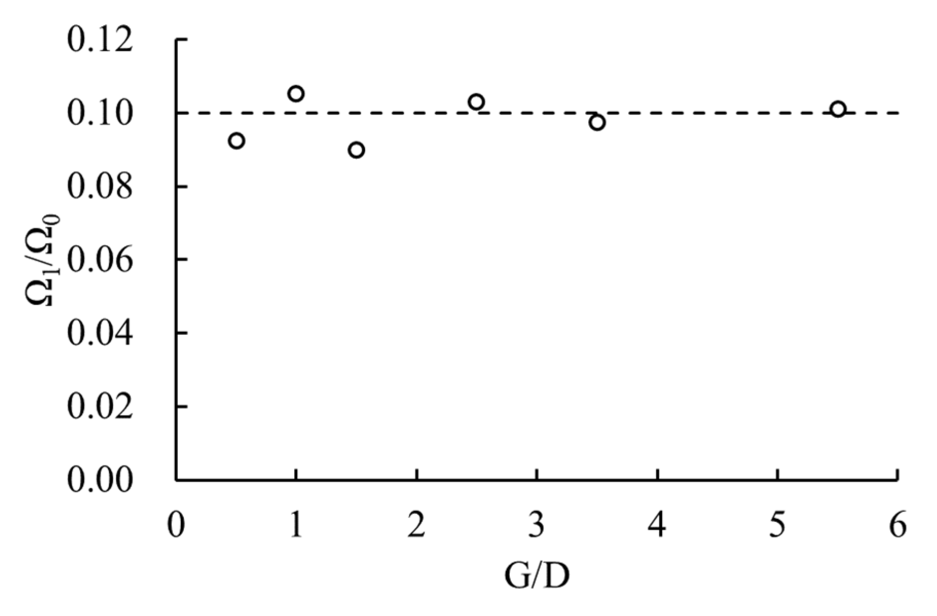
The vorticity at the initial position of the wake was modified as , and the vorticity reaching the outlet of the channel was modified as . The relationship between and G/D is shown in Figure 9.
The vorticity of the vortex street around a square cylinder attenuated along the flow direction, and the boundary constraint affecting only the law of the initial vorticity attenuated along the flow direction. When the vortex moved to the area beyond 18 D behind the square cylinder, the vorticity tended to be stable, and there was no obvious attenuation along the flow direction. Under different boundary constraint degrees, the vorticity attenuated to 10% of the initial vorticity. For the flow around a square cylinder, the final attenuation degree of the vorticity of the vortex street was unrelated to the distribution, shape, and motion law of the vortex street caused by the boundary constraints.
3.3. Fluid Characteristics of the Flow around a Square Cylinder
The time-averaged drag coefficient and the Strouhal number were used as the evaluation indexes of the fluid characteristics of the four flow pattern classifications L1, L2, L3, and T in the flow around a square cylinder. The range of the boundary gap ratio G/D was 0.5 to 5.5. The relationship between and G/D, when was between 0.005 and 2000 is shown in Figure 10. The relationship between and G/D, when was between 150 and 2000 is shown in Figure 11.
The relationship between and in the flow around a square cylinder was similar to that of the flow around a cylinder. The relationship between and G/D, in Figure 10 is expressed by Equation (8a–c):
Under the four different flow patterns, values were all related to the boundary constraint. After the boundary constraint degree was increased, the resistance of the square cylinder was significantly enhanced. In Figure 10a,b and Equation (8a–c), it can be seen that, though was different, the law of changing with G/D was consistent, and all flow patterns conformed to the negative square relationship. When G/D ≥ 3.5, the boundaries were far away from the square cylinder. Its constraint effect was small, and tended to with the increase in G/D (see Equation (8a–c)). is the drag coefficient of the flow around a square cylinder without the constraint effect. When G/D < 3.5, the constraint effect of the boundaries was significantly enhanced, and grew exponentially with the decrease in G/D. For example, in a turbulence flow pattern, when was 1200 and when G/D ≥ 3.5, the boundaries were far away from the square cylinder, and was close to the value of without a constraint effect. Between them, when G/D = 3.5, then , which was only 1.8% larger than (). Here, the impact of the boundary constraint on was minimal. When G/D < 3.5, as the boundary constraint was strengthened, increased. After G/D < 1.0, the distance between the cylinder and the boundaries was smaller than the width of the cylinder, and increased significantly. When G/D = 0.5, reached 4.81.
The relationship between and was not affected by the boundary constraint degree. It can be seen in Figure 10a,b that under each G/D, the law of the change of with can be divided into three stages. When ≤ 6, was linearly related to , and decreased with the increase in . When 6 < ≤ 1100, had a quadratic relation with . decreased first and then increased as increased. After > 1100, did not change with and became a specific value.
It can be seen from Equation (9a–c) that the relationship between and G/D conformed to the hyperbolic functional relationship at each . In Figure 11a,b, when G/D < 3.5, the boundary constraints increased the shedding frequency of vortices, and when G/D < 1.5, the shedding frequency of vortices increased significantly, and the amplification of increased significantly.
Like , the relationship between and was also unaffected by the boundary constraint degree. and had a quadratic relation, which is shown in Figure 11a,b and Equation (9a–c). Under each G/D, first decreased and then increased with the elevation of , and reached the minimum value when = 1100.
3.4. Flow Pattern Division of Flow around a Square Cylinder
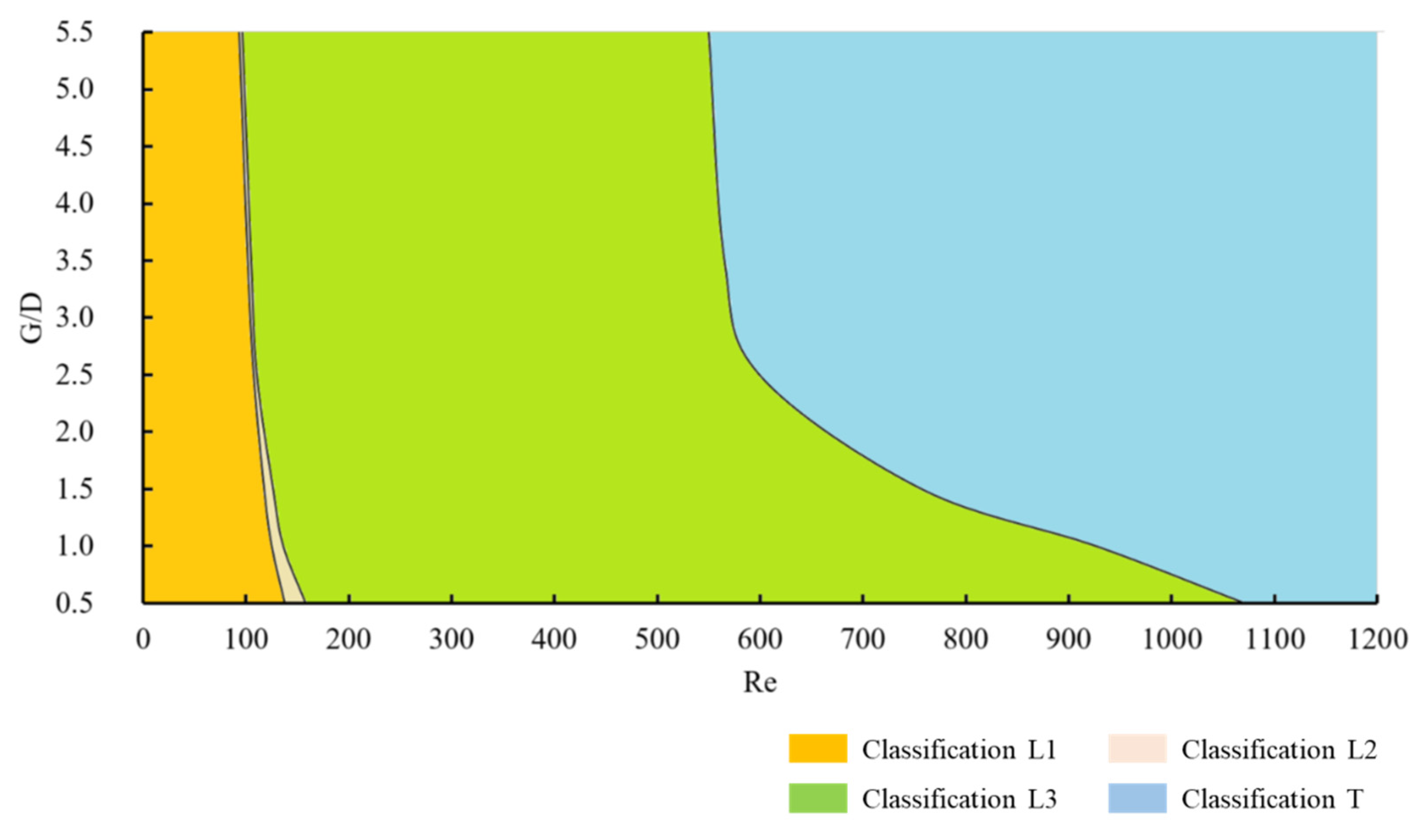
The four flow patterns (L1, L2, L3, T) around a square cylinder under different were all affected by the boundary constraint. When G/D was 0.5~5.5, the dichotomy method was used to locate the range corresponding to each wake flow pattern of the flow around a square cylinder under a different boundary constraint degree, and the flow pattern classification map of the flow around a square cylinder is shown in Figure 12.
The increase in the boundary constraint led to the appearance of Classification T (turbulence phase), which required a larger , and the ranges corresponding to classifications L1 (stable attached vortex phase), L2 (unstable attached vortex phase), and L3 (laminar vortex street phase) also expanded. When G/D < 2.5, the increase in the constraint degree resulted in a significant expansion of the range corresponding to Classification L3. As seen in Figure 4d, Figure 5, and Figure 6, after being constrained by boundaries, the steady state of the staggered distribution and regular movement downstream of the vortex streets in the original turbulence flow pattern was destroyed, and vortices were shed from the square cylinder and randomly diverged downstream to both sides of the boundaries. The vortices of the flow around a square cylinder were constrained by the channel boundaries. The divergence of vortices to both sides was blocked, and they could only move downstream. The relative stability of the flow around a square cylinder was maintained, which caused the appearance of Classification T, requiring a larger . Thus, the boundary constraint had a rectification effect on the flow around a square cylinder, which improved the stability of the flow pattern and moderated the occurrence of turbulence.
4. Conclusions
In the present study, numerical simulation was used to study the flow characteristics around a square cylinder under different boundary constraints. The major results are summarized as follows:
- (1)
- The flow pattern around a square cylinder can be divided into four types under different Reynolds numbers: L1 (stable attached vortex phase), L2 (unstable attached vortex phase), L3 (laminar vortex street phase), and T (turbulence phase). The boundary constraint does not change the flow pattern around a square cylinder.
- (2)
- In the flow pattern of a laminar vortex street, the boundary constraint squeezes the vortex shapes, pushes the vortex centres to the channel boundaries, and reduces the distance between the vortices along the flow direction, but the boundary constraint cannot change the attenuation law and magnitude of the vorticity along the flow direction.
- (3)
- When the constraint degree of boundaries exceeds a specific level (G/D < 3.5), the time-averaged drag coefficient of the cylinder and the shedding frequency of the attached vortices can increase significantly.
- (4)
- The variation law of the drag coefficient of the flow around a square cylinder and the shedding frequency of attached vortices with the Reynolds number will not be affected by the boundary constraint degree.
- (5)
- The boundary constraint rectifies the wake flow pattern around a square cylinder, and the appearance of turbulence requires a larger Reynolds number. With the increase of boundary constraint degree, the expansion of the of Reynolds number range corresponding to the flow pattern of the laminar vortex street is the most significant.
Author Contributions
Conceptualization, Z.X.; methodology, Z.X.; software, Z.X.; validation, Z.X., F.W., A.G. and W.Z.; formal analysis, Z.X.; investigation, Z.X.; resources, S.W. and X.W.; data curation, Z.X.; writing—original draft preparation, Z.X.; writing—review and editing, Z.X., S.W. and W.X.; visualization, Z.X.; supervision, S.W. and X.W.; project administration, S.W. and X.W.; funding acquisition, S.W. and X.W. All authors have read and agreed to the published version of the manuscript.
Funding
This research was funded by the National Natural Science Foundation of China, grant number 51909169; and the Research Foundation for Basic Research (Natural Science Foundation) of Jiangsu Province, China, grant number SBK2019042181.
Institutional Review Board Statement
Not applicable.
Informed Consent Statement
Not applicable.
Data Availability Statement
Not applicable.
Conflicts of Interest
The authors declare no conflict of interest.
References
- Williamson, C.H.K. Defining a universal and continuous Strouhal–Reynolds number relationship for the laminar vortex shedding of a circular cylinder. Phys. Fluids 1988, 31, 2742–2744. [Google Scholar] [CrossRef]
- Wang, Y.L.; Liu, Y.Z.; Miao, G.P. Three-Dimensional Numerical Simulation of Viscous Flow around Circular Cylinder. J. Shanghai Jiaotong Univ. 2001, 2001, 1461–1469. [Google Scholar]
- Behara, S.; Mittal, S. Wake transition in flow past a circular cylinder. Phys. Fluids 2010, 22, 114104. [Google Scholar] [CrossRef]
- Taneda, S. Experimental investigation of the wakes behind cylinders and plates at low Reynolds numbers. J. Phys. Soc. Jpn. 1956, 11, 302–307. [Google Scholar] [CrossRef]
- Coutanceau, M.; Bouard, R. Experimental determination of the main features of the viscous flow in the wake of a circular cylinder in uniform translation. Part 1. Steady flow. J. Fluid Mech. 1977, 79, 231–256. [Google Scholar] [CrossRef]
- Thoman, D.C.; Szewczyk, A.A. Time-dependent viscous flow over a circular cylinder. Phys. Fluids 1969, 12, II-76–II-86. [Google Scholar] [CrossRef]
- Collins, W.M.; Dennis, S.C.R. Flow past an impulsively started circular cylinder. J. Fluid Mech. 1973, 60, 105–127. [Google Scholar] [CrossRef]
- Coutanceau, M.; Defaye, J.R. Circular cylinder wake configurations: A flow visualization survey. Apply Mech. Rev. 1991, 44, 255–305. [Google Scholar] [CrossRef]
- Wu, M.H.; Wen, C.Y.; Yen, R.H.; Weng, M.C.; Wang, A.B. Experimental and numerical study of the separation angle for flow around a circular cylinder at low Reynolds number. J. Fluid Mech. 2004, 515, 233–260. [Google Scholar] [CrossRef] [Green Version]
- Couder, Y. The observation of a shear flow instability in a rotating system with a soap membrane. J. De Phys. Lett. 1981, 42, 429–431. [Google Scholar] [CrossRef]
- Chomaz, J.M. The dynamics of a viscous soap film with soluble surfactant. J. Fluid Mech. 2001, 442, 387–409. [Google Scholar] [CrossRef] [Green Version]
- Beizaie, M.; Gharib, M. Fundamentals of a liquid (soap) film tunnel. Exp. Fluids 1997, 23, 130–140. [Google Scholar] [CrossRef]
- Kim, N.; Kim, H.; Park, H. An experimental study on the effects of rough hydrophobic surfaces on the flow around a circular cylinder. Phys. Fluids 2015, 27, 85113. [Google Scholar] [CrossRef]
- Palau-Salvador, G.; Stoesser, T.; Fröhlich, J.; Kappler, M.; Rodi, W. Large eddy simulations and experiments of flow around finite-height cylinders. Flow Turbul. Combust. 2010, 84, 239–275. [Google Scholar] [CrossRef]
- Sen, S.; Mittal, S.; Biswas, G. Flow past a square cylinder at low Reynolds numbers. Int. J. Numer. Methods Fluids 2011, 67, 1160–1174. [Google Scholar] [CrossRef]
- Tong, B.; Zhu, B.; Zhou, B.K. Numerical Simulation of Flow around Square Cylinder. Chin. Q. Mech. 2002, 23, 77–81. [Google Scholar]
- Yang, F.; Zhou, Z.; Tang, G.; Lu, L. Steady flow around a square cylinder near a plane boundary. Ocean Eng. 2021, 222, 108599. [Google Scholar] [CrossRef]
- Prsic, M.A.; Ong, M.C.; Pettersen, B.; Myrhaug, D. Large Eddy Simulations of flow around a circular cylinder close to a flat seabed. Mar. Struct. 2016, 46, 127–148. [Google Scholar] [CrossRef] [Green Version]
- Chen, L.F.; Wu, G.X. Boundary shear flow past a cylinder near a wall. Appl. Ocean Res. 2019, 92, 101923. [Google Scholar] [CrossRef]
- Lei, C.; Cheng, L.; Kavanagh, K. Re-examination of the effect of a plane boundary on force and vortex shedding of a circular cylinder. J. Wind Eng. Ind. Aerodyn. 1999, 80, 263–286. [Google Scholar] [CrossRef]
- Nishino, T.; Roberts, G.T.; Zhang, X. Vortex shedding from a circular cylinder near a moving ground. Phys. Fluids 2007, 19, 25103. [Google Scholar] [CrossRef] [Green Version]
- Lei, C.; Cheng, L.; Armfield, S.W.; Kavanagh, K. Vortex shedding suppression for flow over a circular cylinder near a plane boundary. Ocean Eng. 2000, 27, 1109–1127. [Google Scholar] [CrossRef]
- Khabbouchi, I.; Guellouz, M.S.; Nasrallah, S.B. A study of the effect of the jet-like flow on the near wake behind a circular cylinder close to a plane wall. Exp. Therm. Fluid Sci. 2013, 44, 285–300. [Google Scholar] [CrossRef]
- Durao, D.F.G.; Gouveia, P.S.T.; Pereira, J.C.F. Velocity characteristics of the flow around a square cross section cylinder placed near a channel wall. Exp. Fluids 1991, 11, 341–350. [Google Scholar] [CrossRef]
- Martinuzzi, R.J.; Bailey, S.C.C.; Kopp, G.A. Influence of wall proximity on vortex shedding from a square cylinder. Exp. Fluids 2003, 34, 585–596. [Google Scholar] [CrossRef]
- Bailey, S.C.C.; Kopp, G.A.; Martinuzzi, R.J. Vortex shedding from a square cylinder near a wall. J. Turbul. 2002, 3, 3. [Google Scholar] [CrossRef]
- Bearman, P.W.; Zdravkovich, M.M. Flow around a circular cylinder near a plane boundary. J. Fluid Mech. 1978, 89, 33–47. [Google Scholar] [CrossRef]
- Grass, A.J.; Raven, P.W.J.; Stuart, R.J.; Bray, J.A. The influence of boundary layer velocity gradients and bed proximity on vortex shedding from free spanning pipelines. J. Energy Resour. Technol. 1984, 106, 70–78. [Google Scholar] [CrossRef]
- Shi, L.L.; Liu, Y.Z.; Wan, J.J. Influence of wall proximity on characteristics of wake behind a square cylinder: PIV measurements and POD analysis. Exp. Therm. Fluid Sci. 2010, 34, 28–36. [Google Scholar] [CrossRef]
- Zhou, J.; Qiu, X.; Li, J.; Liu, Y. Vortex evolution of flow past the near-wall circular cylinder immersed in a flat-plate turbulent boundary layer. Ocean Eng. 2022, 260, 112011. [Google Scholar] [CrossRef]
- Price, S.J.; Sumner, D.; Smith, J.G.; Leong, K.; Païdoussis, M.P. Flow visualization around a circular cylinder near to a plane wall. J. Fluids Struct. 2002, 16, 175–191. [Google Scholar] [CrossRef]
- Zhang, Z.; Ji, C.; Alam, M.M.; Xu, D. DNS of vortex-induced vibrations of a yawed flexible cylinder near a plane boundary. Wind Struct. 2020, 30, 465–474. [Google Scholar] [CrossRef]
- Trias, F.X.; Gorobets, A.; Oliva, A. Turbulent flow around a square cylinder at Reynolds number 22,000: A DNS study. Comput. Fluids 2015, 123, 87–98. [Google Scholar] [CrossRef] [Green Version]
- Dong, S.; Karniadakis, G.E.; Ekmekci, A.; Rockwell, D. A combined direct numerical simulation–particle image velocimetry study of the turbulent near wake. J. Fluid Mech. 2006, 569, 185–207. [Google Scholar] [CrossRef] [Green Version]
- Behera, S.; Saha, A.K. Characteristics of the flow past a wall-mounted finite-length square cylinder at low Reynolds number with varying boundary layer thickness. J. Fluids Eng. 2019, 141, 1–17. [Google Scholar] [CrossRef]
- Ji, C.N.; Zhang, Z.M.; Alam, M.M.; Xu, D. Three-dimensional DNS of vortex-induced vibrations of an inclined flexible cylinder near a plane boundary. In Proceedings of the 2019 World Congress on Advances in Structural Engineering and Mechanics, Jeju Island, Republic of Korea, 17–21 September 2019. [Google Scholar]
- Rodi, W.; Ferziger, J.H.; Breuer, M.; Pourquié, M. Status of large eddy simulation: Results of a workshop. Trans. -Am. Soc. Mech. Eng. J. Fluids Eng. 1997, 119, 248–262. [Google Scholar] [CrossRef]
- Voke, P.R. Flow past a square cylinder: Test case LES2. In Direct and Large-Eddy Simulation II; Springer: Dordrecht, The Netherlands, 1997; pp. 355–373. [Google Scholar] [CrossRef]
- Kahil, Y.; Benhamadouche, S.; Berrouk, A.S.; Afgan, I. Simulation of subcritical-Reynolds-number flow around four cylinders in square arrangement configuration using LES. Eur. J. Mech.-B/Fluids 2019, 74, 111–122. [Google Scholar] [CrossRef]
- Rodi, W. Comparison of LES and RANS calculations of the flow around bluff bodies. J. Wind Eng. Ind. Aerodyn. 1997, 69, 55–75. [Google Scholar] [CrossRef]
- Grigoriadis, D.G.E.; Bartzis, J.G.; Goulas, A. LES of the flow past a rectangular cylinder using the immersed boundary concept. Int. J. Numer. Methods Fluids 2003, 41, 615–632. [Google Scholar] [CrossRef]
- Khan, N.B.; Ibrahim, Z.; Bin Mohamad Badry, A.B.; Jameel, M.; Javed, M.F. Numerical investigation of flow around cylinder at Reynolds number = 3900 with large eddy simulation technique: Effect of spanwise length and mesh resolution. Proc. Inst. Mech. Eng. Part M J. Eng. Marit. Environ. 2019, 233, 417–427. [Google Scholar] [CrossRef]
- Kanaris, N.; Grigoriadis, D.; Kassinos, S. Three dimensional flow around a circular cylinder confined in a plane channel. Phys. Fluids 2011, 23, 64106. [Google Scholar] [CrossRef] [Green Version]
- Norberg, C. Flow around rectangular cylinders: Pressure forces and wake frequencies. J. Wind Eng. Ind. Aerodyn. 1993, 49, 187–196. [Google Scholar] [CrossRef]
- Blackburn, H.M.; Henderson, R.D. A study of two-dimensional flow past an oscillating cylinder. J. Fluid Mech. 1999, 385, 255–286. [Google Scholar] [CrossRef] [Green Version]
- Sadeque, M.A.; Rajaratnam, N.; Loewen, M.R. Flow around cylinders in open channels. J. Eng. Mech. 2008, 134, 60–71. [Google Scholar] [CrossRef]
- Yuce, M.I.; Kareem, D.A. A numerical analysis of fluid flow around circular and square cylinders. J. -Am. Water Work. Assoc. 2016, 108, E546–E554. [Google Scholar] [CrossRef]
- Zaid, M.; Yazdanfar, Z.; Chowdhury, H.; Alam, F. Numerical modeling of flow around a pier mounted in a flat and fixed bed. Energy Procedia 2019, 160, 51–59. [Google Scholar] [CrossRef]
- Lan, X.J.; Zhao, W.W.; Wan, D.C.; Zou, L. Numerical simulation of low-Re flow around a square cylinder by MPS method. Ocean Eng. 2002, 40, 83–92. [Google Scholar] [CrossRef] [Green Version]
- Gera, B.; Sharma, P.K. CFD analysis of 2D unsteady flow around a square cylinder. Int. J. Appl. Eng. Res. 2010, 1, 602. [Google Scholar]
- Okajima, A. Strouhal numbers of rectangular cylinders. J. Fluid Mech. 1982, 123, 379–398. [Google Scholar] [CrossRef] [Green Version]
- Wang, J.C. Direct Numerical Simulation of Medium Reynolds Flow Past Square Cylinder. Master’s Thesis, China Ship Research and Development Academy, Beijing, China, 2016. [Google Scholar]
- Lyn, D.A. Phase-averaged turbulence measurements in the separated shear layer region of flow around a square cylinder. In Proceedings of the 23rd Congress of the International Association for Hydraulic Research, Ottawa, ON, Canada, 21–25 August 1989. [Google Scholar]
- Bouris, D.; Bergeles, G. 2D LES of vortex shedding from a square cylinder. J. Wind Eng. Ind. Aerodyn. 1999, 80, 31–46. [Google Scholar] [CrossRef]
- Fureby, C.; Tabor, G.; Weller, H.G.; Gosman, A.D. Large eddy simulations of the flow around a square prism. AIAA J. 2000, 38, 442–452. [Google Scholar] [CrossRef]
- Cao, Y.; Tamura, T. Large-eddy simulations of flow past a square cylinder using structured and unstructured grids. Comput. Fluids 2016, 137, 36–54. [Google Scholar] [CrossRef]
- Bearman, P.W.; Obasaju, E.D. An experimental study of pressure fluctuations on fixed and oscillating square-section cylinders. J. Fluid Mech. 1982, 119, 297–321. [Google Scholar] [CrossRef]
- Lee, B.E. The effect of turbulence on the surface pressure field of a square prism. J. Fluid Mech. 1975, 69, 263–282. [Google Scholar] [CrossRef]
Figure 1.
Schematic diagram of the computational domain and boundary conditions.

Figure 2.
The location of nine zones for grid generation.

Figure 3.
Computational grids distribution of the computational domain; (a) total computational grids distribution; (b) detailed computational grids distribution close to the square cylinder.
Figure 3.
Computational grids distribution of the computational domain; (a) total computational grids distribution; (b) detailed computational grids distribution close to the square cylinder.

Figure 4.
Different classifications of flow distribution around a square cylinder; (a) Classification L1 ( = 40); (b) Classification L2 ( = 95); (c) Classification L3 ( = 400); and (d) Classification T ( = 1000).
Figure 4.
Different classifications of flow distribution around a square cylinder; (a) Classification L1 ( = 40); (b) Classification L2 ( = 95); (c) Classification L3 ( = 400); and (d) Classification T ( = 1000).


Figure 5.
Flow pattern around a square cylinder under different boundary constraint degrees when . (a) G/D = 5.5; (b) G/D = 3.5; (c) G/D = 2.5; (d) G/D = 1.5; (e) G/D = 1.0; and (f) G/D = 0.5.
Figure 5.
Flow pattern around a square cylinder under different boundary constraint degrees when . (a) G/D = 5.5; (b) G/D = 3.5; (c) G/D = 2.5; (d) G/D = 1.5; (e) G/D = 1.0; and (f) G/D = 0.5.


Figure 6.
Trajectory of the vortex centres of the flow around a square cylinder under different boundary constraint degrees when . (a) G/D = 5.5; (b) G/D = 3.5; (c) G/D = 2.5; (d) G/D = 1.5; (e) G/D = 1.0; and (f) G/D = 0.5.
Figure 6.
Trajectory of the vortex centres of the flow around a square cylinder under different boundary constraint degrees when . (a) G/D = 5.5; (b) G/D = 3.5; (c) G/D = 2.5; (d) G/D = 1.5; (e) G/D = 1.0; and (f) G/D = 0.5.


Figure 7.
Average distance of the vortex centres of the flow around a square cylinder along the flow direction under different boundary constraint degrees when .
Figure 7.
Average distance of the vortex centres of the flow around a square cylinder along the flow direction under different boundary constraint degrees when .

Figure 8.
Variation of the vorticity of the flow around a square cylinder along the flow direction under different boundary constraint degrees.
Figure 8.
Variation of the vorticity of the flow around a square cylinder along the flow direction under different boundary constraint degrees.

Figure 9.
Relationship between and G/D in the vortex street flow pattern.

Figure 10.
Relationship of nd G/D, . (a) versus and ; (b) versus ; and (c) versus .


Figure 11.
Relationship of and G/D, . (a) versus and ; (b) versus ; and (c) versus .


Figure 12.
Flow pattern classification map of the flow around a square cylinder under boundary constraint.
Figure 12.
Flow pattern classification map of the flow around a square cylinder under boundary constraint.


Table 1.
An overview of the flow pattern classifications of the flow around a square cylinder.
| Flow Pattern Classification | Flow Characteristics | |
|---|---|---|
| L1 | Stable attached vortex phase | Stable and symmetrical attached vortices formed by the separated flow behind a cylinder (Taneda, 1956 [4]; Coutanceau and Bouard, 1977 [5]). |
| L2 | Unstable attached vortex phase | The attached vortices behind a cylinder are asymmetric, fluctuating sinusoidally. |
| L3 | Laminar vortex street phase | Attached vortex shedding appearing behind a cylinder and forming periodic laminar vortex streets (Thoman and Szewczyk, 1969 [6]; Collins and Dennis, 1973 [7]). |
| T | Turbulence phase | Vortex streets are unstable, attached vortex shedding appearing non-sinusoidally, and turbulence is formed behind a cylinder. |
Table 2.
Grid sizes in nine zones.
| Zone | Grid Length | Grid Width |
|---|---|---|
| 1 | ||
| 2 | ||
| 3 | ||
| 4 | ||
| 5 | ||
| 6 | ||
| 7 | ||
| 8 | ||
| 9 |
Table 3.
Comparison of and of the flow around a square cylinder under different grid resolutions.
| Grids | Total Elements | Re = 40 | Re = 1000 | ||
|---|---|---|---|---|---|
| G1 | 0.125 | 5444 | 1.49 | 1.88 | 0.117 |
| G2 | 0.075 | 15,194 | 1.54 | 2.02 | 0.120 |
| G3 | 0.050 | 33,636 | 1.59 | 2.17 | 0.121 |
| G4 | 0.025 | 134,544 | 1.64 | 2.29 | 0.121 |
| G5 | 0.0125 | 535,076 | 1.67 | 2.39 | 0.122 |
| G6 | 0.0075 | 1,487,034 | 1.69 | 2.42 | 0.122 |
Table 4.
Comparison of and of the flow around a square cylinder under different values between the present and earlier results.
Table 4.
Comparison of and of the flow around a square cylinder under different values between the present and earlier results.
| Source | |||
|---|---|---|---|
| 40 | Sen et al. [15] | 1.67 | - |
| Lan et al. [49] | 1.72 | - | |
| Present | 1.67 | - | |
| 200 | Lan et al. [49] | 1.49 | 0.143 |
| Gera et al. [50] | - | 0.145 | |
| Okajima [51] | 1.50 | 0.141 | |
| Present | 1.49 | 0.141 | |
| 1000 | Lan et al. [49] | 2.23 | 0.122 |
| Okajima [51] | 2.10 | 0.120~0.130 | |
| Wang [52] | 2.40 | 0.124 | |
| Present | 2.39 | 0.122 | |
| 22,000 | Trias et al. [33] | 2.19 | 0.132 |
| Lyn [53] | 2.18 | 0.134 | |
| Bouris et al. [54] | 2.10 | 0.135 | |
| Fureby et al. [55] | 2.11–2.30 | 0.126~0.138 | |
| Cao et al. [56] | - | 0.130 | |
| Bearman et al. [57] | 2.05 | 0.122 | |
| Lee [58] | 2.18 | 0.132 | |
| Present | 2.06 | 0.124 |
Disclaimer/Publisher’s Note: The statements, opinions and data contained in all publications are solely those of the individual author(s) and contributor(s) and not of MDPI and/or the editor(s). MDPI and/or the editor(s) disclaim responsibility for any injury to people or property resulting from any ideas, methods, instructions or products referred to in the content. |
© 2023 by the authors. Licensee MDPI, Basel, Switzerland. This article is an open access article distributed under the terms and conditions of the Creative Commons Attribution (CC BY) license (https://creativecommons.org/licenses/by/4.0/).
Share and Cite
MDPI and ACS Style
Xu, Z.; Wu, S.; Wu, X.; Xue, W.; Wang, F.; Gao, A.; Zhang, W. Analysis of Flow Characteristics around a Square Cylinder with Boundary Constraint. Water 2023, 15, 1507. https://doi.org/10.3390/w15081507
AMA Style
Xu Z, Wu S, Wu X, Xue W, Wang F, Gao A, Zhang W. Analysis of Flow Characteristics around a Square Cylinder with Boundary Constraint. Water. 2023; 15(8):1507. https://doi.org/10.3390/w15081507
Chicago/Turabian StyleXu, Zhun, Shiqiang Wu, Xiufeng Wu, Wanyun Xue, Fangfang Wang, Ang Gao, and Weile Zhang. 2023. "Analysis of Flow Characteristics around a Square Cylinder with Boundary Constraint" Water 15, no. 8: 1507. https://doi.org/10.3390/w15081507
Note that from the first issue of 2016, this journal uses article numbers instead of page numbers. See further details here.