
Influence of Installation Deviation of Thrust Bearing on Oil Film Flow of 1000 MW Hydraulic Turbine Unit
by
 and
and
Zhenwei Ji
1,
Yishu Shi
2,
Xinming Da
1,
Jingwei Cao
2,
Qijun Gong
1,
Zhengwei Wang
2,* and
Xingxing Huang
3
1
Sinohydro Engineering Bureau 4 Co., Ltd., Chengdu 610000, China
2
Department of Energy and Power Engineering, Tsinghua University, Beijing 100084, China
3
S.C.I. Energy, Future Energy Research Institute, Seidengasse 17, 8706 Zurich, Switzerland
*
Author to whom correspondence should be addressed.
Water 2023, 15(9), 1649; https://doi.org/10.3390/w15091649
Submission received: 20 February 2023
/
Revised: 17 April 2023
/
Accepted: 19 April 2023
/
Published: 23 April 2023
(This article belongs to the Special Issue Advancements in the Complex Vortex Flow in Hydraulic Machinery)
Abstract
:The thrust bearing, as the only part bearing the axial load, is extremely important in vertical hydroelectric generating units. Its working condition directly affects the safe and reliable operation of the hydroelectric generating unit. However, during operation, the oil film is easily damaged under the influence of complex factors. Installation deviation is a key point that can cause temperature and pressure changes in the oil film, affecting the force on the bearing. This article takes the thrust bearing model of the 1000 MW Francis turbine unit of the Baihetan Power Station as the research object. Based on the fluid–solid coupling theory and CFD technology, the oil film characteristics of thrust bearings are analyzed, and the influence of inclination angles and installation deviation on the oil film flow performance of thrust bearings is discussed. The results show that as the inclination angle changes from 0.0030° to 0.0048°, the axial force changes from 856 t to 368 t, and there is an approximate linear correlation between them. The radial installation deviation has an effect on the axial force. Under the optimal working condition of an inclination angle of 0.0039°, when the radial deviation of the pad changes from 0 mm to 1 mm, the axial force changes from 1573 t to 1275 t. In the process of unit installation, it is necessary to pay attention to the installation deviation of the pad. The results provide guidance for the installation of the bearing, which helps to ensure the safe and stable operation of the station.
1. Introduction
At present, China’s energy structure is still dominated by coal; it produces the highest carbon emission levels in the world [1]. Under the policy of “carbon neutrality”, China has seen an acceleration of the shift to green energy to reduce carbon emissions and mitigate the generation of greenhouse gases [2,3]. Hydropower, as the earliest developed and most mature energy in China, has the advantages of cost efficiency, flexible operation, a clean and renewable resource base, and development potential [4,5]. Hydraulic turbines comprise important hydroelectric generating unit equipment [6]. Among the various types of hydraulic turbines, the Francis turbine is widely used in hydropower projects because of its compact structure, high efficiency, and wide applicable head range [7,8].
In recent years, with the continuous improvement of hydraulic design methods, material performance, and manufacturing technology, the maximum efficiency of Francis turbines has reached more than 96%, and the cavitation resistance of hydropower units has been greatly improved [8]. The research on hydraulic design has been relatively mature. However, at present, hydroelectric generating units development has allowed large capacity and large size, and there are many issues to be studied. With the increase of the size, the structural support stiffness of the hydraulic turbine is weakened [6], which increases the likelihood of resonance. The increasing capacity of the turbine unit leads to an increase in water flow, which creates higher requirements for operational stability. Therefore, in the process of increasing the capacity of the unit, it is necessary to carry out related research on the load components to ensure their safety and reliability during actual operation of the unit.
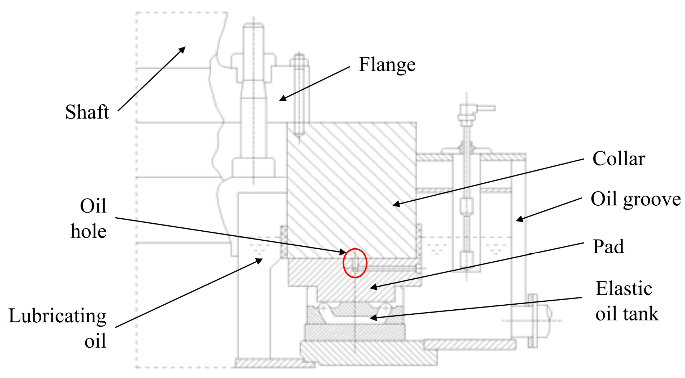
The thrust bearing, as the only part bearing the axial load, is an extremely important part of the vertical hydroelectric generating unit [9,10]. Its working state and environment directly affect the safe and stable operation of the unit [2]. Thrust bearings are located in the lower bearing bracket below the rotor of the generator and include the shaft, thrust block, collar, pads, and support components, as shown in Figure 1 There is a wedge-shaped gap between the pads and the collar. According to the hydrodynamic lubrication theory, a wedge-shaped oil film with certain pressure is formed when the shaft rotates. During the operation, the oil film is easily damaged under the influence of complex factors, and the surface of the thrust pad is prone to wear, which directly affects the life of the thrust bearing and the normal operation of the unit [4,11]. Thrust bearings generally work under high load and high speed [12]. In this working process, the oil element friction between pad and rotating collar generates heat, which increases the temperature of the oil element and produces an uneven distribution of temperature in the oil film. The influence of the thermal effect leads to a decrease of lubricating oil viscosity and bearing surface deformation, thus changing the lubrication performance of the bearings [13].Therefore, it is of great significance to carry out the research on the oil film characteristics of thrust bearings.
Many scholars conducted studies on oil film characteristics. In 1886, Osborne Reynolds used mathematical methods to describe the phenomenon of fluid dynamic pressure and detail the characteristics of the two moving surfaces of the haulage motor. According to the dynamic principle, Osborne Reynolds proposed the Reynolds equation to describe the lubricating oil, which laid the theoretical foundation for the study of the oil film characteristics of thrust bearings [15,16,17]. Dowson derived the generalized Reynolds equation by considering the viscosity and density of oil film in terms of oil film thickness and proposed the thermo-hydro-dynamic (THD) analysis method, which not only considered the influence of the temperature increase of thrust bearings on the viscosity of lubricating oil, but also considered the heat transfer characteristics between the collar and the thrust pad in the temperature rise calculation [18]. In this method, temperature was the main factor affecting the viscosity of lubricating oil. With the increase of temperature, the intermolecular distance of the lubricating oil expanded, and the intermolecular force decreased, resulting in the decrease of viscosity. The change of viscosity directly determined whether good dynamic pressure lubrication is present and its role in bush-burning accidents. Therefore the thermodynamic analysis of thrust bearings is an important element in the study of load performance [19].Tieu, using the THD analysis method, established a variational principle with viscous dissipation for thin-film flow. Considering the change of lubricating oil viscosity with temperature and pressure, the Reynolds equation and the energy equation were solved to obtain the three-dimensional oil film thickness, pressure, and temperature distribution of the bearing [20]. Michaud et al. proposed a numerical procedure to analyze the steady and transient three-dimensional THD behaviors of bearings. The Newton-Raphson method and finite element formula were used to solve the Reynolds equation, in-film energy equation, and in-solid heat transfer equation. The results of the two-dimensional calculation and three-dimensional calculation were compared, which showed that three-dimensional analysis was necessary [21]. Anvar Ahmadkhah et al. established a thermos-hydrodynamic model, considering the thermal effect of the components at the fluid–solid interface, and calculated the lubrication characteristics (viscosity and density) of the main bearing. In their analysis, viscosity temperature equations were used for different lubrication pressures and temperatures. The density and viscosity of the rotating wall were compared quantitatively and qualitatively using the color image segmentation method. The authors concluded that increasing the average heat transfer coefficient was a factor to reduce the thermal stress and high temperature point of the rigid part of the bearing system [22]. Li et al. carried out thermo-hydrodynamic lubrication analysis of misaligned journal bearings, considering the axial movement of the journal. The lubrication characteristics of the bearings were studied during the axial movement of the misaligned journal. The results showed that the influence of eccentricity on bearing lubrication performance was more obvious when the inclination angle and eccentricity were larger [23].
The installation deviation also has a great influence on the oil film flow. In this paper, a bearing deviation model is established to study the oil film flow caused by the installation deviation in the assembly process, which can provide a theoretical basis and reference for the analysis of oil film characteristics and online monitoring technology of oil film thickness of thrust bearings in the future.
2. Numerical Techniques
The thermo-hydrodynamic lubrication numerical calculation method based on computational fluid dynamics can be solved with the momentum equation, continuity equation, and energy equation simultaneously, which can account for the influence of fluid inertia force and volume force and simulate the lubrication characteristics of thrust bearings more accurately.
2.1. Continuity Equation
The oil fluid domain is discretized into microelements by the finite element method. In each microelement, the sum of the masses flowing into the microelement through the control surface per unit of time is equal to the increment of the masses in the microelement per unit of time. It is also known from the continuum assumption that the integrand is continuous in the flow field and differentiable in the first order, and the continuity equation in differential form can be obtained:
where is the fluid density and is the velocity in direction.
2.2. Navier–Stokes Equations
The oil film flow can be described by Reynolds average Navier-Stokes equations [24]:
where is the fluid density, is the fluid pressure, is the stress tensor, including vertical and tangential stress components, and is the Reynolds stress in the nonlinear convective term of the non-average equation.
2.3. Energy Equation
In the equation below, is the fluid pressure; is the fluid temperature; λ is thermal conductivity of lubricating oil; is the enthalpy change; is the total enthalpy, ; is the contribution of turbulent kinetic energy, ; is the additional turbulent flux; is the viscous effect term caused by the viscous stress. Since this term describes the heat generation caused by the viscous friction force of the fluid, it cannot be omitted when calculating the hydrodynamic characteristics of the lubricant film where the viscous force is very significant. is the work done by the volume force.
2.4. SST k-ω Turbulence Model
There are two kinds of flow in the fluid domain of the thrust bearing: laminar flow in the oil film and turbulent flow around the tile. The SST turbulence model can satisfy this characteristic well, and it can obtain appropriate flow transport characteristics by limiting eddy viscosity. It is a kind of - model, including two equations of and ω.
The turbulent kinetic energy equation for is as follows:
The turbulent frequency equation for is as follows:
where, and are the kinetic energy of turbulence, ; and are the dissipation term of k and ω, , , and are model constants; is the diffusion term.
2.5. Viscosity Temperature Equation
As the viscosity performance of the lubricating oil changes with temperature, the increase of temperature will reduce the viscosity of the lubricating oil, leading to the decline of lubricating performance. The viscosity temperature relationship can be described as follows [14]:
where, is the liquid viscosity, is the absolute temperature, is the reference temperature (25 °C), and is the viscosity at temperature ; .
3. Theoretical Model
3.1. Model of the Oil Film
Based on the thrust bearing model (as shown in Figure 2) of the mixed flow water turbine unit of the Baihetan Power Station, a non-deviation model including the shaft, thrust block, collar, pads, and support components is established, as shown in Figure 3a. The oil film is located between the pads and the collar, as shown in Figure 3b. The support tiles are placed on the pads, as shown in Figure 3c. They are a type of multi-oil groove support tile, supporting the force of the pad; they play an important role in the deformation of the pad and thus affect the operation performance of the thrust bearing. The pad has an alloy layer on top, the material of which is Babbitt alloy. Babbitt alloy is a kind of bearing alloy with antifriction properties that is widely used in large bearing rotating machinery. There are 24 bearings in a circle; these bear axial forces collectively. The schematic diagram of each size is shown in Figure 4a, and the parameters of each size are shown in Table 1.
Assuming that the thrust load is distributed on the pad surface evenly, the cyclic symmetry model of the bearing can be established, as shown in Figure 4b; that is, the fluid domain is 1/24 of the lubricating oil in the tank, and solid domain contains a pad, a support tile, and 1/24 of the thrust runner collar.
There is a very thin wedge-shaped oil film between the collar and pads during the hydroelectric generating unit operation. If the oil film is too thin, it will lead to the increase of the temperature of the thrust pad during operation; if the oil film is too thick, its bearing capacity will decrease [25,26].
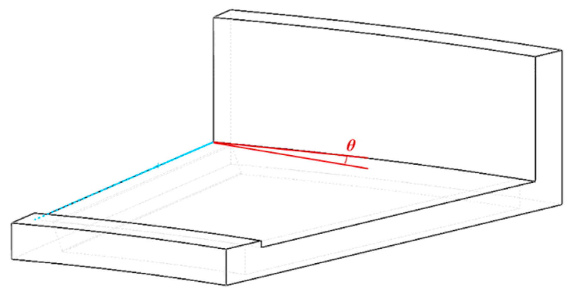
The inclination , is defined as shown in the Figure 5, as the angle between the pad upper surface and the collar. Based on inclination , the oil film thickness has a clear correlation with θ through geometric relation. According to the installation data of the Baihetan Power Station, the maximum thickness of the oil film during operation is 0.1 mm, that is, the thickness of oil film on the left side is 0.1 mm. The relationship between the inclination angle and the right oil film thickness is shown in Table 2.
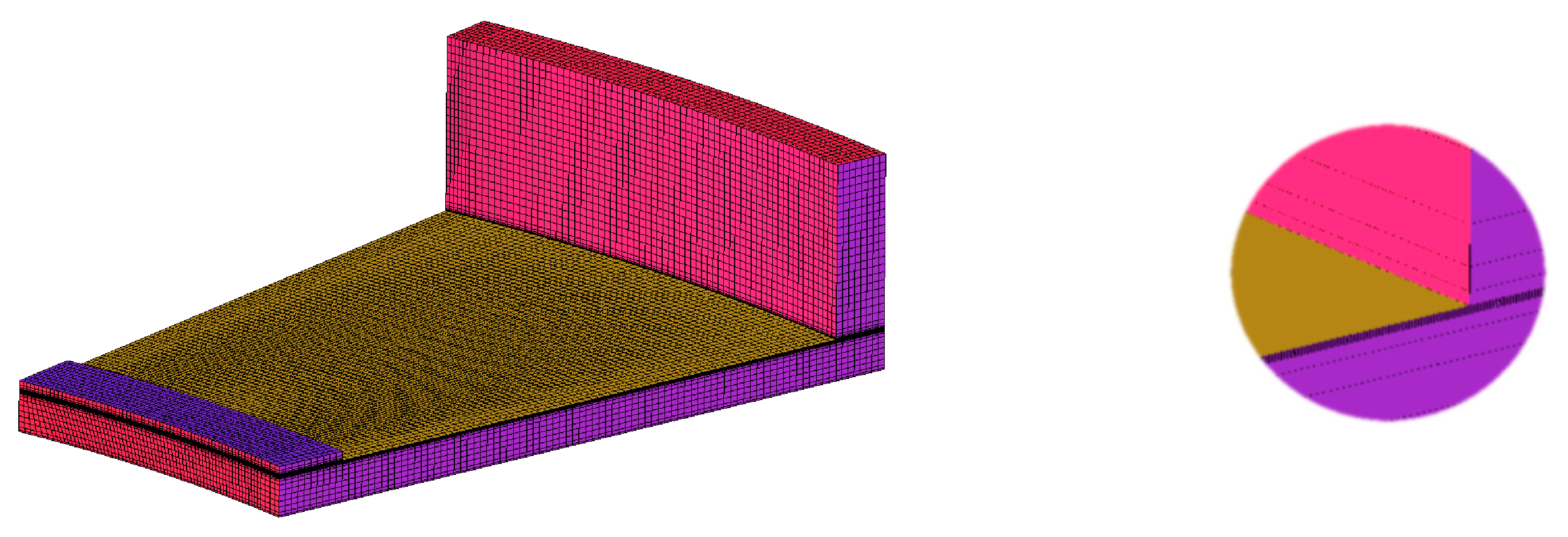
The mesh model was drawn using ICEM CFD software, as shown in the Figure 6. To ensure accuracy, 10 layers of mesh were drawn on a layer of oil film with a maximum thickness of 0.1 mm.
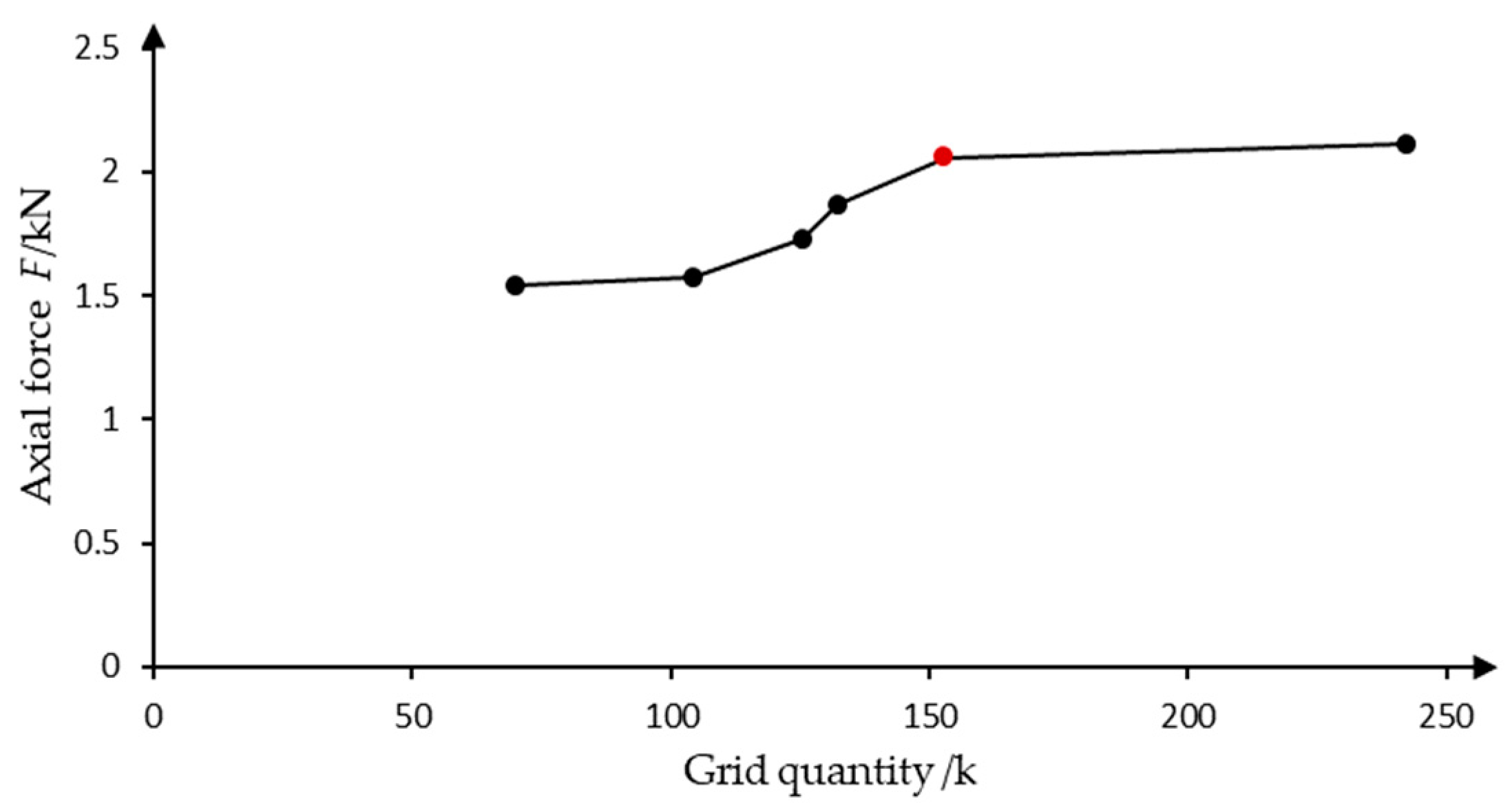
In order to prove that the mesh itself has no effect on the results of the overall numerical simulation, mesh independence verification is necessary. In general, the denser the mesh is within a certain limit, the more accurate the result is. However, beyond this limit, increasing the mesh density has a negligible effect on improving the accuracy of the calculation, but increasing the mesh number will greatly increase the calculations required, resulting in a waste of resources. Based on the angle of 0.0039°, which is the inclination angle corresponding to the optimum operating condition of the unit, the calculation was carried out for different mesh models to find the optimal mesh number, and the results are shown in Figure 7. It was found that 10-layer oil film mesh is the best option, with a mesh number of 152,960. The mesh number is mainly related to the number of layers; the relationship between mesh layer number and mesh number is shown in Table 3. In addition, when the number of mesh layers of the oil film increases to 15, the mesh quality of the oil film will become poor because the maximum thickness of the oil film is only 0.1 mm, thus affecting the calculation accuracy.
3.2. Thrust Bearing THD Model
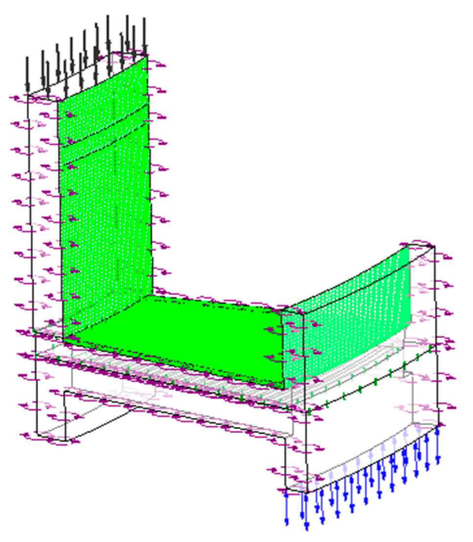
The flow inlet boundary is adopted in the oil tank inlet, with an oil intake of 3.125 kg/s, while an open boundary allowing the lubricating oil to flow in and out of the tank is adopted in the outlet. The surface of the collar is set as a rotating wall. Using the cyclic symmetry model, the rotating periodic interface is set to ensure the continuity of flow and heat transfer between all the pads, as shown in Figure 8. The interface between the collar and the lubricating fluid domain is set as the surface of rotation, as shown in Figure 8, green surface.
The fluid domain uses Mobil DTE 746 lubricant (ASTM D2270), the pad and the collar are made of alloy steel, and the pad coating is babbitt.
3.3. Model Considering Radial and Circumferential Deviation
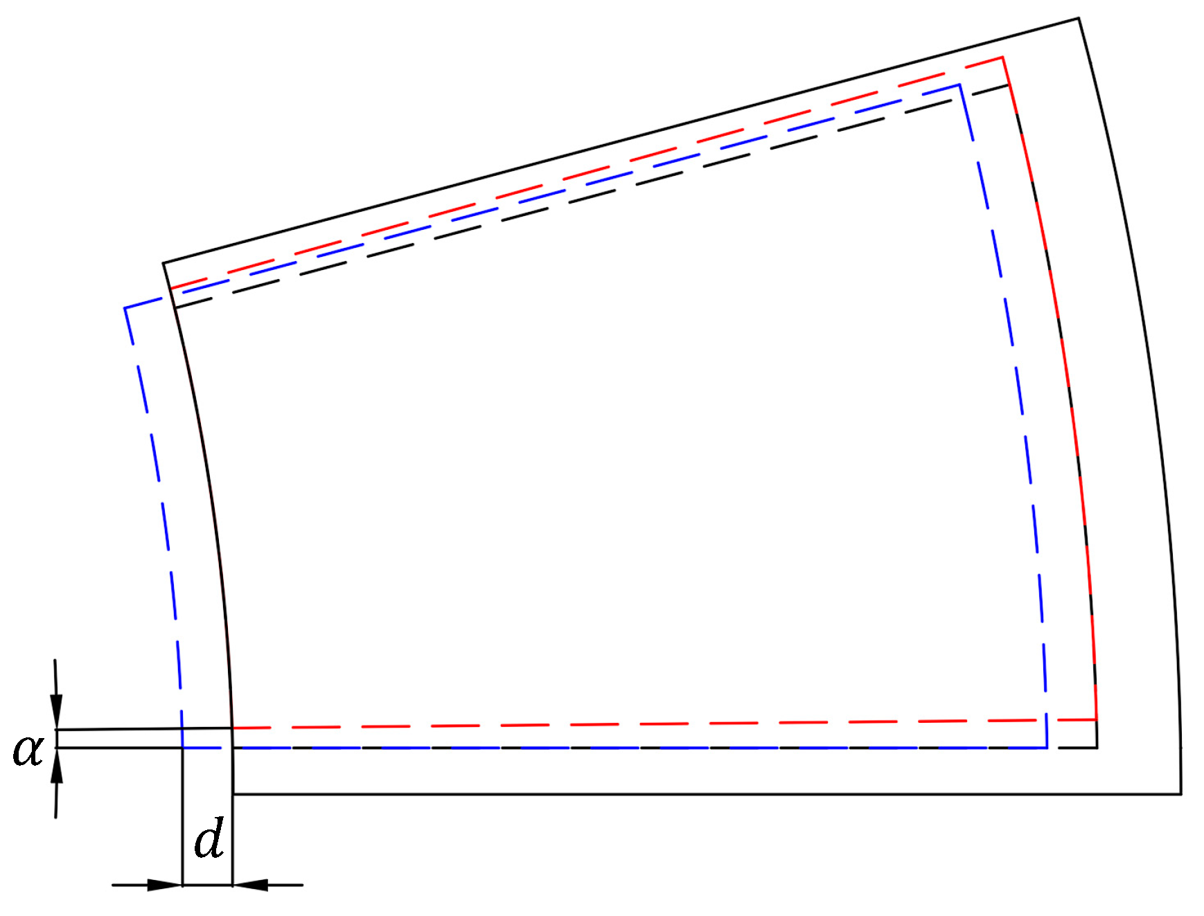
To analyze the influence of thrust bearing installation deviation on oil film flow performance, radial and circumferential installation models are established. The radial installation deviation is formed by offsetting the thrust pad by a distance along the radius direction. The circumferential deviation is formed by rotating the pad counter-clockwise at an angle around the axis, as shown in Figure 9.
4. Results and Discussion
4.1. Flow Characteristics
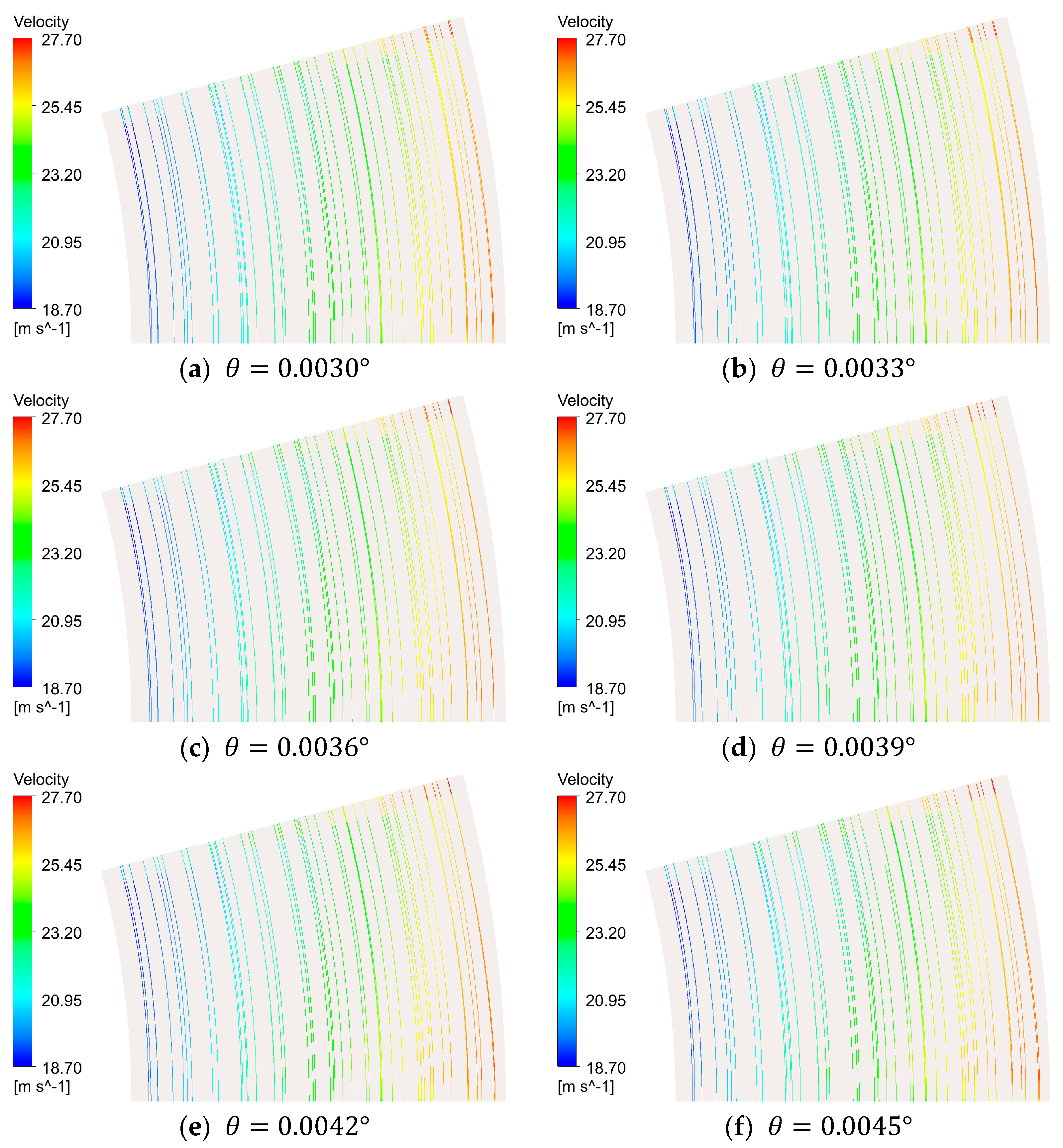
The thermo-hydrodynamic numerical calculation was carried out for the thrust bearing model of the Francis turbine, and the oil film flow characteristics were analyzed. At the rated speed of 111.1 rpm, the turbine unit rotates to produce a wedge-shaped oil film. The streamline on the collar with different inclination is shown in Figure 10. The results show that the lubricating oil in wedge-shaped oil film flows along the circular direction, and the velocity increases with the increase of the radius. With the increase of inclination , the flow velocity of the lubricating oil increases.
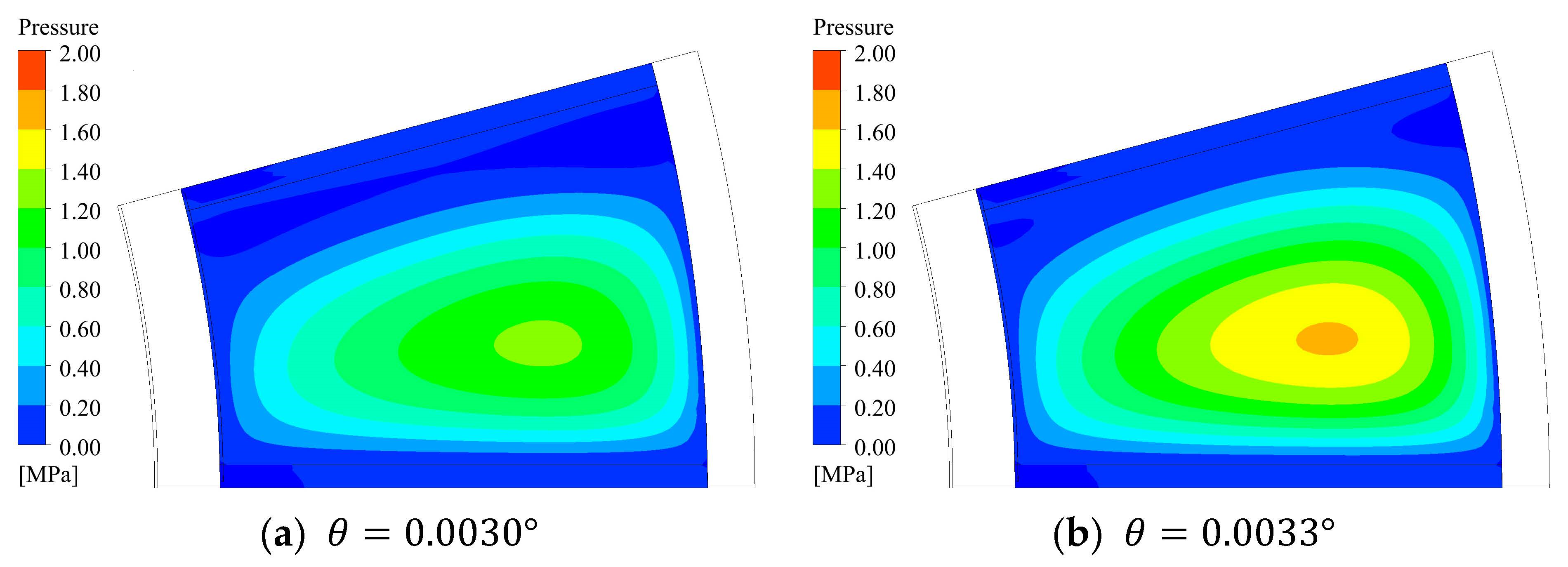
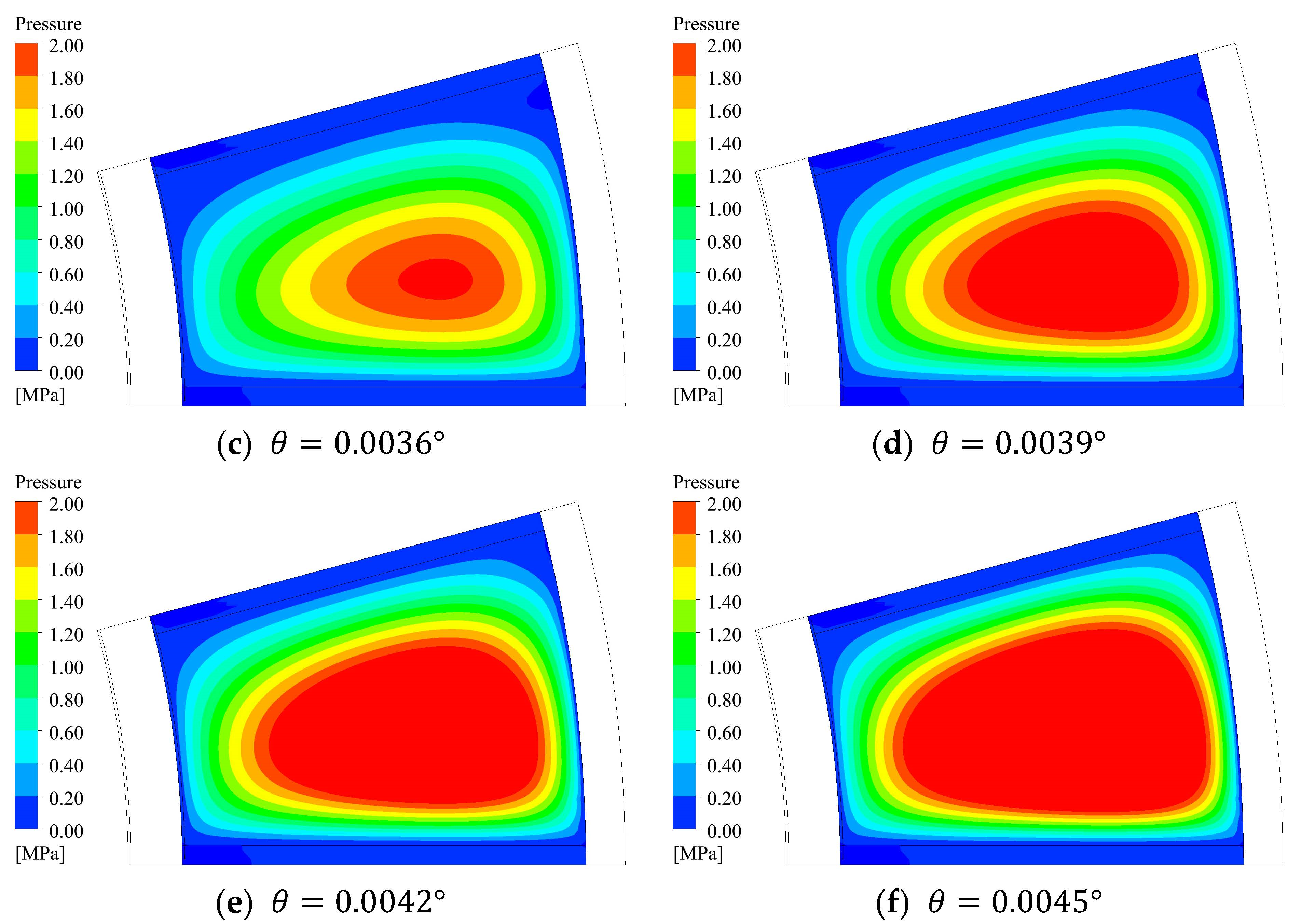
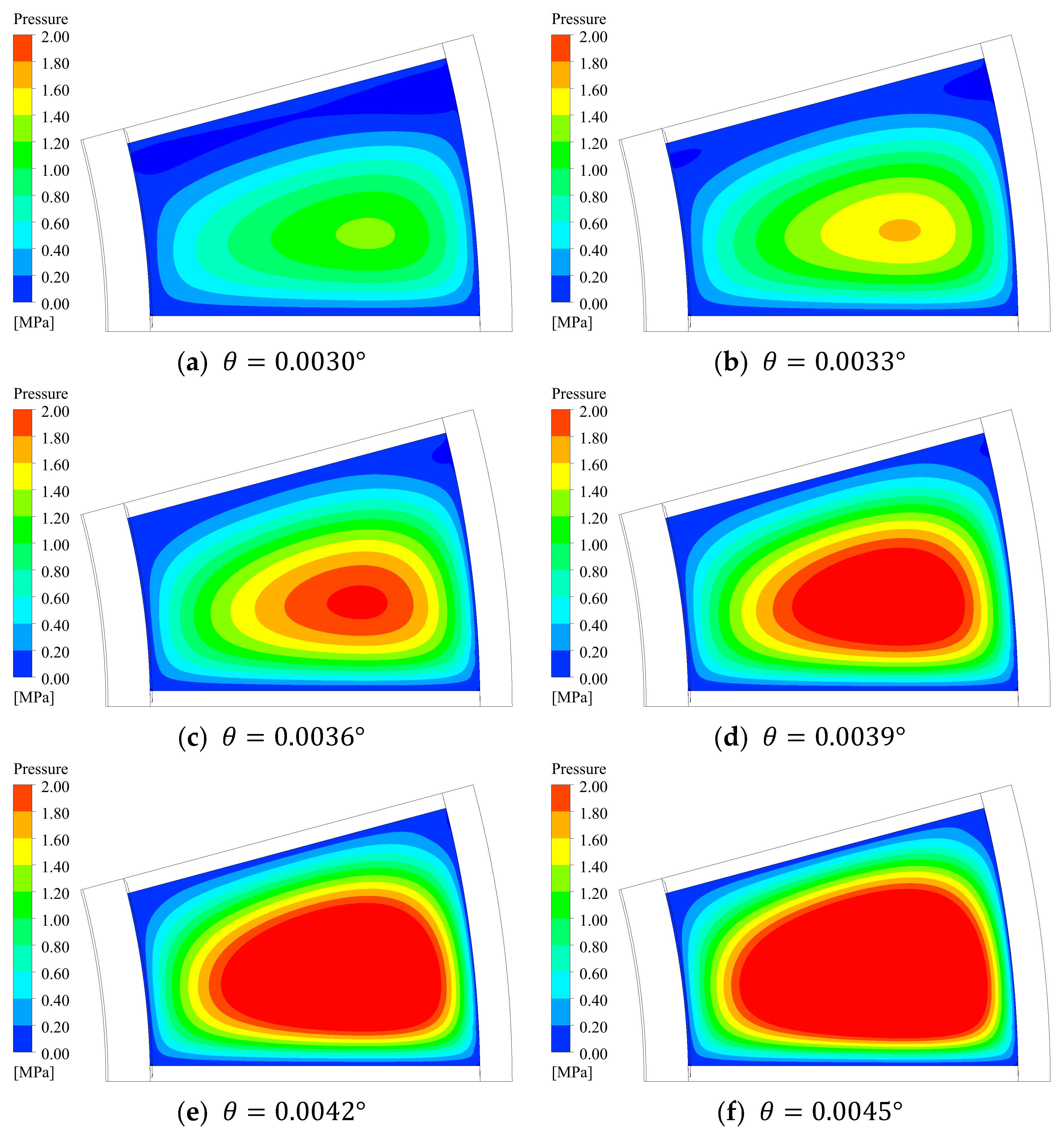
The pressure and temperature distributions also change with the different inclination . The pressure distribution on the collar during operation can be obtained using different angles , as shown in Figure 11. The results show that, on the surface of the collar, the oil pressure increases gradually from the outside to the middle; however, the highest point of the pressure is not in the center but deviates slightly to the rotation direction. With the increase of the inclination , the pressure on the collar surface increases gradually. When the inclination is 0.0045°, the maximum pressure is 3.76 MPa.
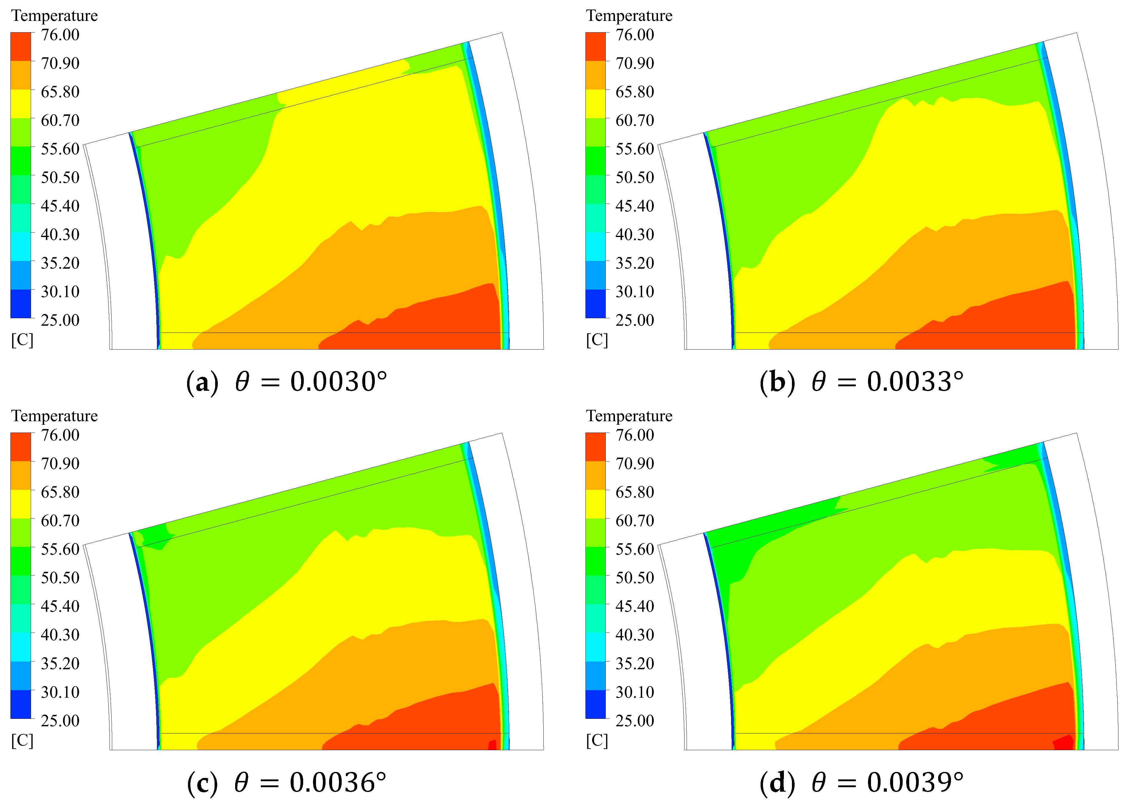
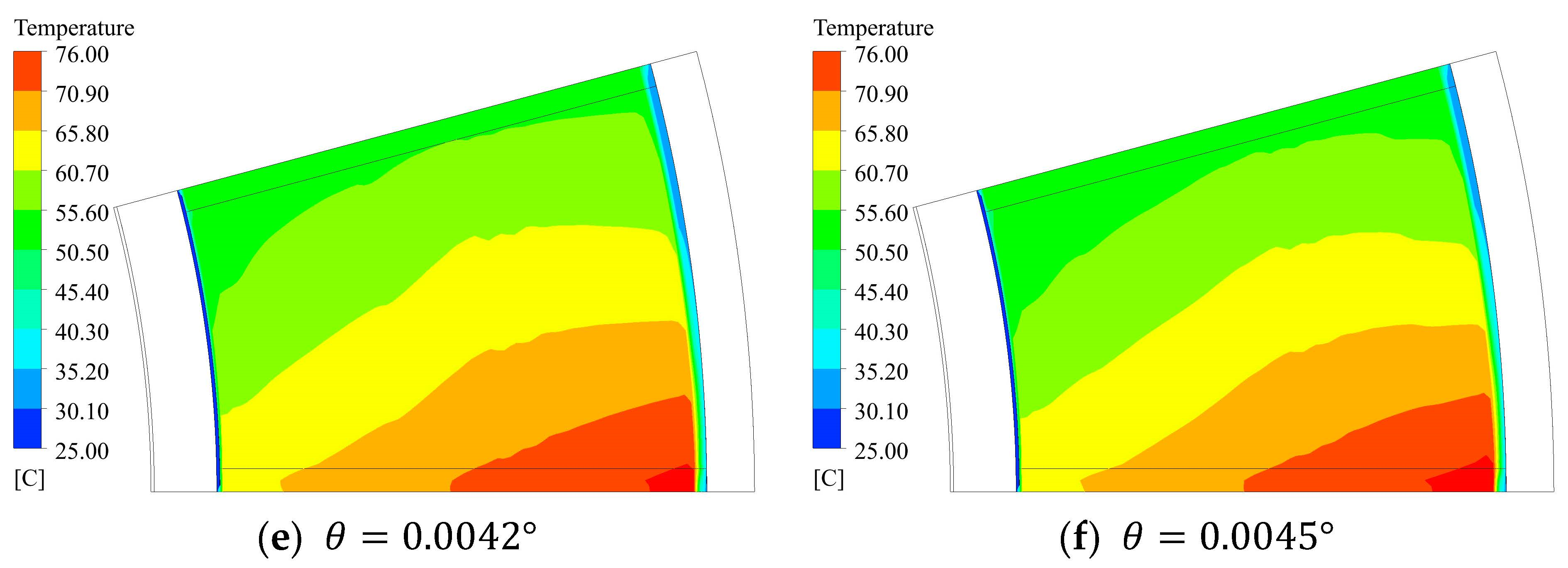
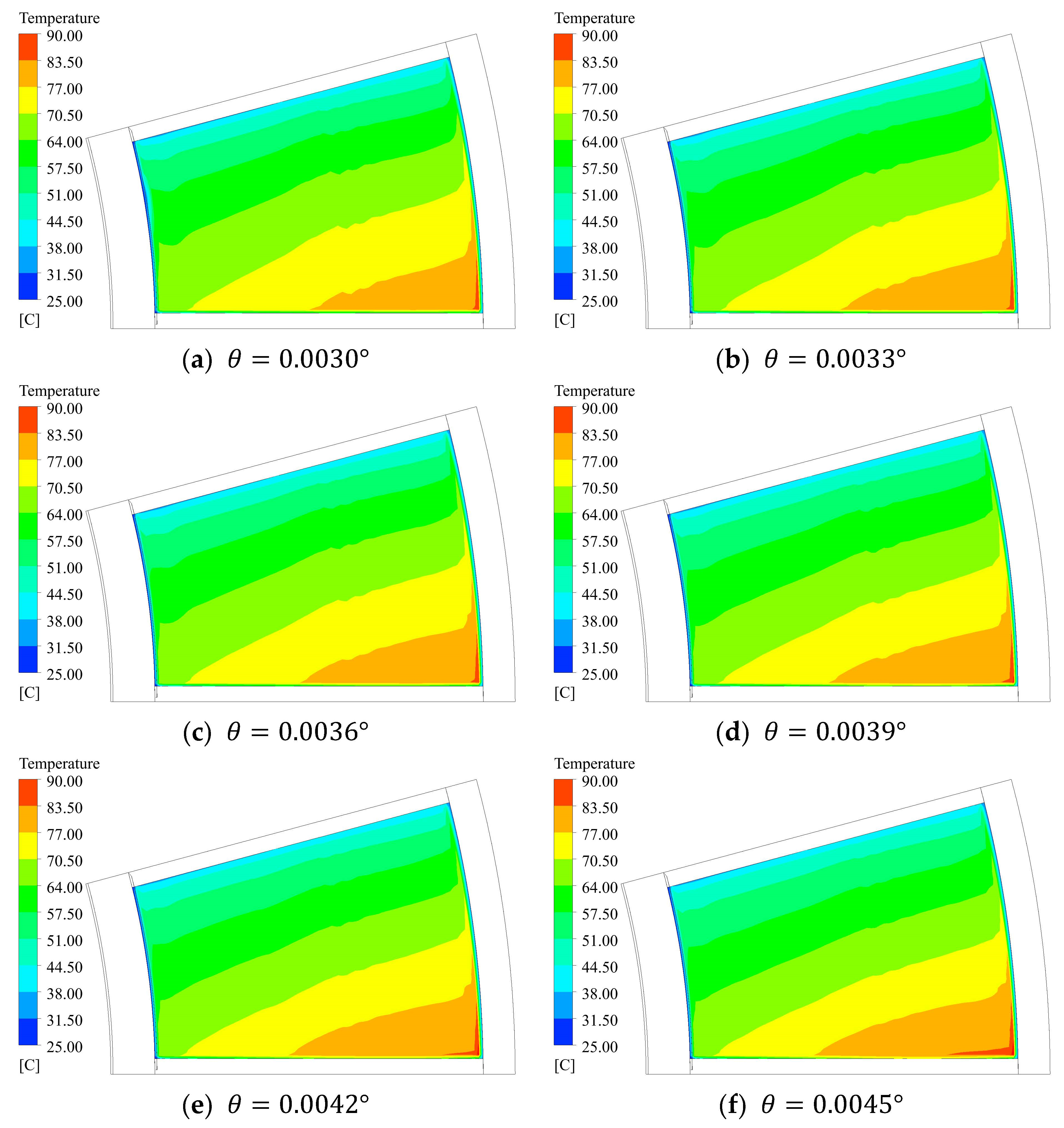
The temperature distribution on the collar is shown in Figure 12. The results show that on the surface of the collar, the temperature increases with the increase of the radius, along the rotation direction; the temperature is the highest on the side near the rotation direction on the outer edge. The temperature increases with the inclination , reaching a maximum temperature of 78.07 °C at the inclination of 0.0045°. When the inclination of the pad increases, the thickness of the oil film decreases, which leads to an increase of pressure in the oil film and a rise in temperature.
The pressure distribution on the pad’s upper surface is shown in Figure 13. The distribution on the pad’s upper surface is the same as the collar surface. The results show that, on the pad’s upper surface, the oil pressure also increases gradually from the outside to the middle. With the increase of the inclination , the pressure on the collar surface increases gradually.
The temperature distribution on pad upper surface is shown in the Figure 14. The result show that, the temperature of the upper surface of the pad is higher than that of the surface of the collar. The temperature increases with the increase of the radius, and increases along the rotation direction, and the temperature reaches the highest on the side near the rotation direction on the outer edge, consistent with the collar surface. The temperature increases with the inclination , reaching a maximum temperature of 92.33 °C at the inclination of 0.0045°.
4.2. Relationship between Load and Inclination Angle
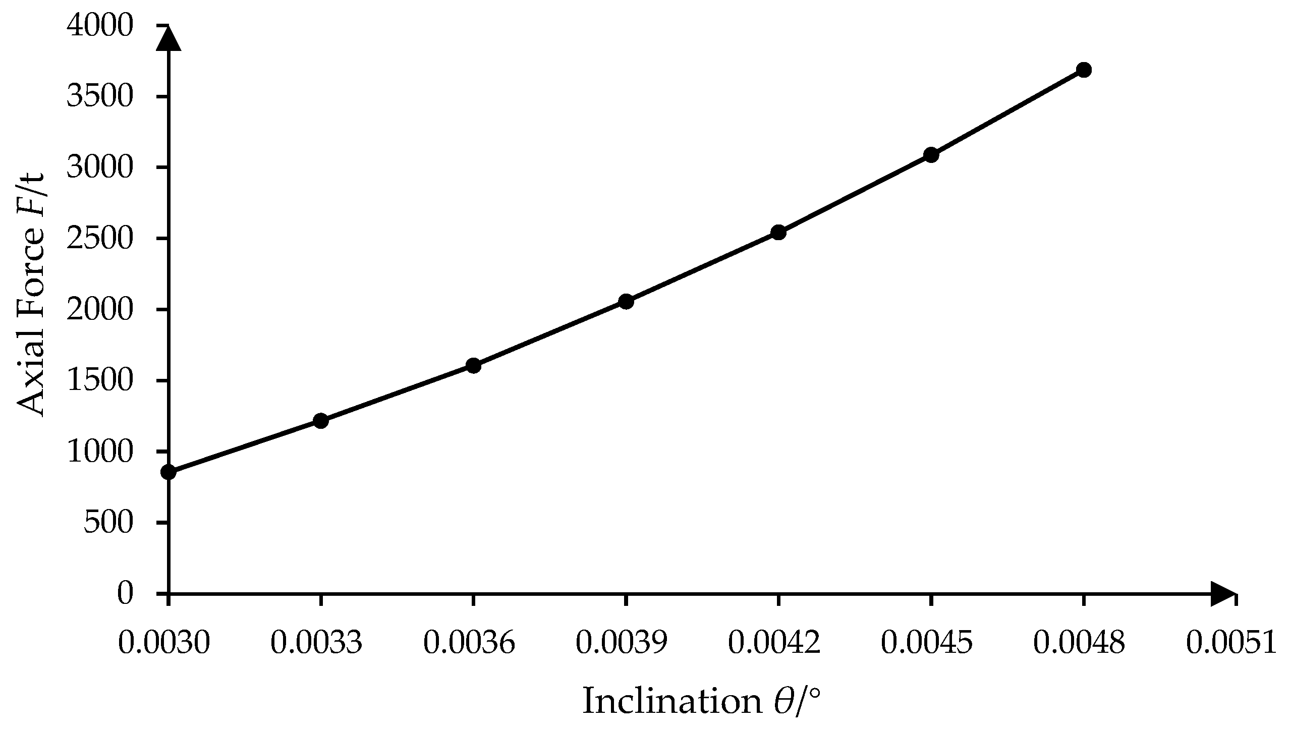
During the rotation of the unit, the wedge-shaped oil film produces an axial force. The axial force varies with the inclination . Through numerical calculation, the variation curve of axial force with inclination is obtained, as shown in Figure 15. With the increase of inclination , the dynamic pressure force increases, so the axial force borne by the thrust bearing increases.
4.3. Oil Film Characteristics under Different Working Conditions
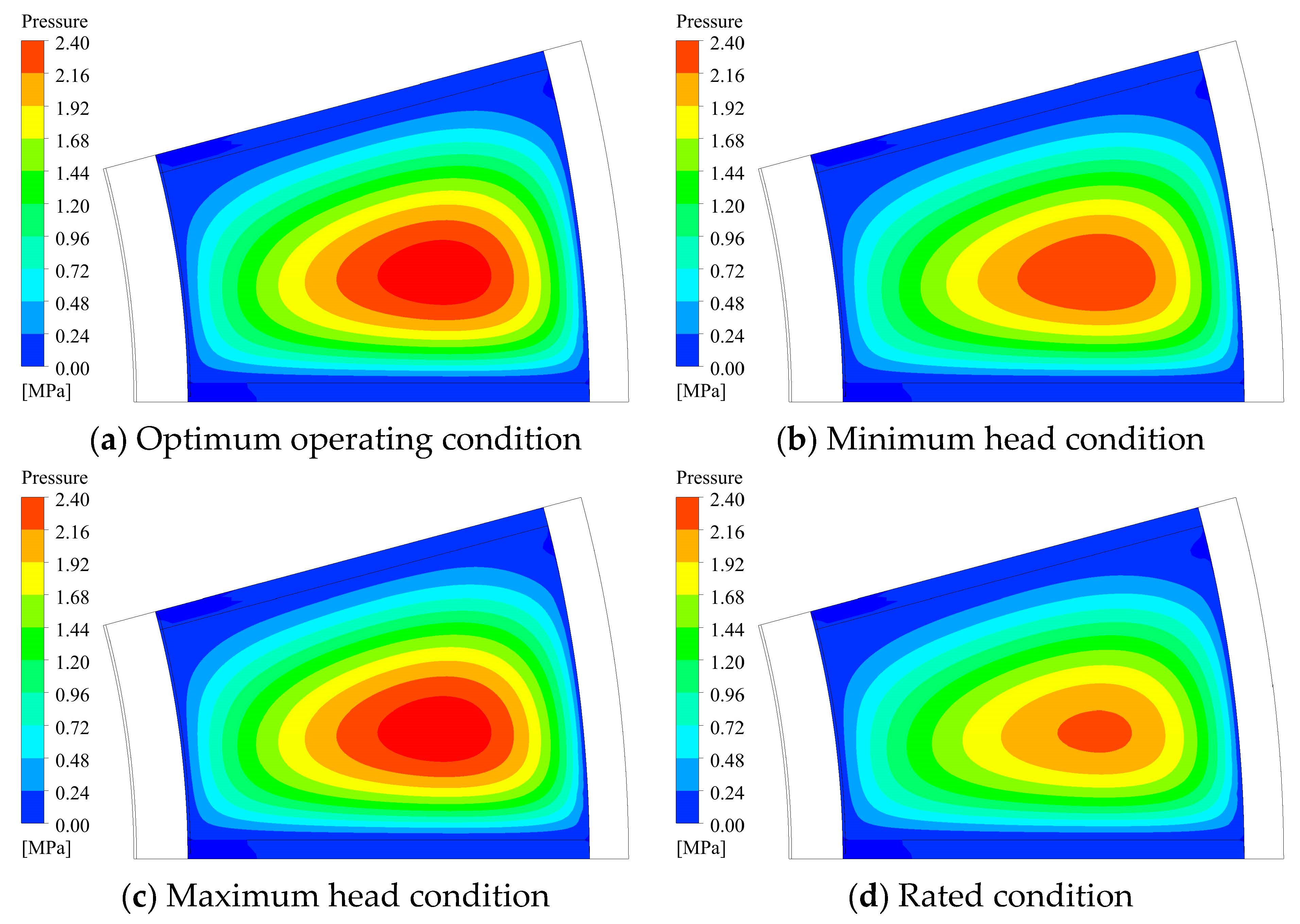
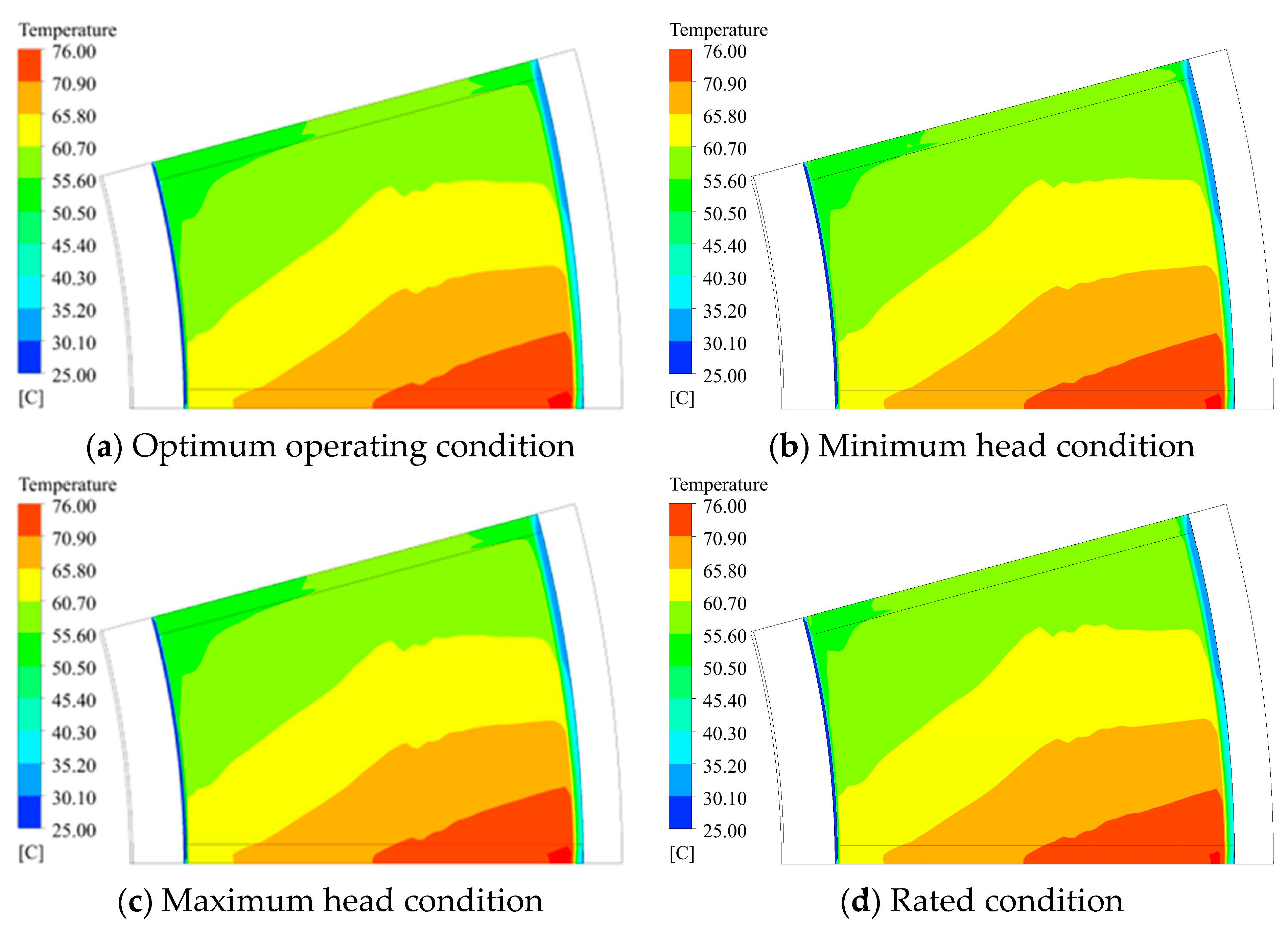
Based on the above, the inclination of the wedge-shaped oil film as well as the temperature and pressure in the oil film are analyzed under the optimum working condition, minimum working condition, maximum working condition, and rated working condition of the bearing.
The axial force of the unit has the following relationship with the unit weight and hydraulic thrust :
where . G and can be determined from the operation data of the Baihetan Power Station.
Therefore, the axial force of bearings under different working conditions can be calculated according to the hydraulic thrust and unit weight. According to the - curve shown in Figure 15, the oil film inclination can be obtained, and the temperature and pressure in the oil film can be calculated. The results are shown in Table 4.
The temperature and pressure distributions of the oil film on the collar are shown in Figure 16 and Figure 17, respectively. The results show that under the optimum operating condition, the maximum pressure of the collar surface is 2.57 MPa, and the maximum temperature is 76.72 °C. Under the minimum head condition, the maximum pressure of the collar surface is 2.40 MPa, and the maximum temperature is 76.49 °C. Under the maximum head condition, the maximum pressure of the collar surface is 2.57 MPa, and the maximum temperature is 76.72 °C. Under the rated condition, the maximum pressure of the collar surface is 2.23 MPa, and the maximum temperature is 76.29 °C.
4.4. Influence of Deviation
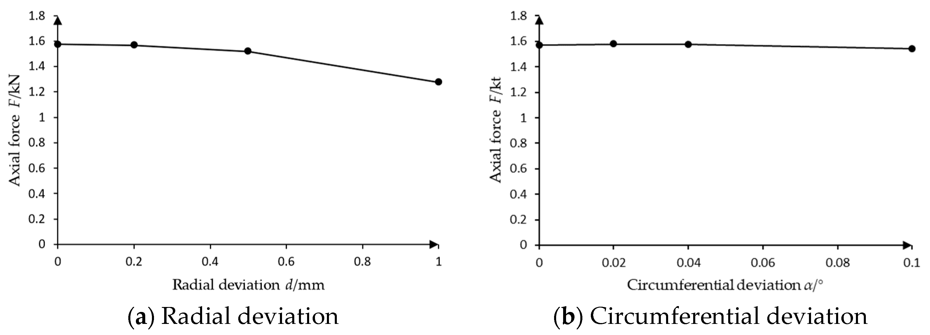
The deviation models of thrust bearings, considering the circumferential deviation and radial deviation , as defined in Figure 9, are numerically calculated. The numerical results show that the axial force of the bearing decreases with the increase of radial installation deviation , as shown in Figure 18a. As the deviation increases, the contact area between the oil film and the pad decreases, and the axial force on the pad decreases. However, the axial force is basically constant with the increase of circumferential deviation , as shown in Figure 18b; the axial deviation has little effect on the contact area.
5. Conclusions
In this paper, the thrust bearing model of the mixed-flow hydraulic turbine unit of the Baihetan Power Station and the deviation model of thrust bearings are established. Using the thermo-elasto-hydrodynamic lubrication numerical calculation method based on computational fluid dynamics to solve the momentum equation, continuity equation, and energy equation, the pressure and temperature characteristics of oil film at different inclination angles and installation deviations are analyzed. The main conclusions are as follows:
- (a)
- Under the action of wedge-shaped oil film, the axial force increases with the increase of the inclination angle, but the temperature and pressure also increase, which may lead to safety risks to a certain extent. Through calculation, under the optimum operating condition, the inclination angle is 0.0039 degrees; under rated condition, the inclination angle is 0.0037 degrees.
- (b)
- The numerical results show that the axial force of the bearing decreases with the increase of radial installation deviation . The axial force is basically constant with the increase of circumferential deviation . Therefore, it is more important to pay attention to the radial installation deviation during the installation.
Overall, in this paper, through numerical analysis, the characteristics of thrust bearing oil film are studied. The research results are helpful for the analysis of oil film lubrication characteristics. Since elastic deformation is not considered in this study, thermo-elasto-hydrodynamic research will be the focus of future work. The research on the influence of installation deviation on oil film characteristics can provide reference for the installation of turbine units and contribute to the safe operation of the units.
Author Contributions
Data curation, Z.J.; investigation, Y.S.; formal analysis, X.D.; methodology, J.C.; project administration, X.H.; software, Q.G.; funding acquisition, Z.W. All authors have read and agreed to the published version of the manuscript.
Funding
The authors are grateful for funding from the Fund Program of State Key Laboratory of Hydroscience and Engineering (No. 2022-KY-06).
Institutional Review Board Statement
Not applicable.
Informed Consent Statement
Not applicable.
Data Availability Statement
Not applicable.
Acknowledgments
The authors gratefully acknowledge the financial support of the project “Research on the mechanism of shaft system dynamic performance change caused by installation deviation of giant hydro-generator units and the engineering applications” from Sinohydro Engineering Bureau 4 Co., LDT., Chengdu, China.
Conflicts of Interest
The authors declare no conflict of interest.
References
- Funan, C. Research on the Dynamic Characteristics of Key Components of Pump Turbine in Transient Processes Based on Fluid-Structure Interaction. Ph.D. Thesis, Tsinghua University, Beijing, China, 2021. [Google Scholar]
- Zhang, Y.; Sun, J.; Zheng, Y.; Ge, X.; Peng, X.; Hong, Y.; Fernandez-Rodriguez, E. Unsteady characteristics of lubricating oil in thrust bearing tank under different rotational speeds in pumped storage power station. Renew. Energy 2022, 201, 904–915. [Google Scholar] [CrossRef]
- Kong, L.; Cao, J.; Li, X.; Zhou, X.; Hu, H.; Wang, T.; Gui, S.; Lai, W.; Zhu, Z.; Wang, Z.; et al. Numerical Analysis on the Hydraulic Thrust and Dynamic Response Characteristics of a Turbine Pump. Energies 2022, 15, 1580. [Google Scholar] [CrossRef]
- Ji, X.-Y.; Li, X.-B.; Su, W.-T.; Lai, X.; Zhao, T.-X. On the hydraulic axial thrust of Francis hydro-turbine. J. Mech. Sci. Technol. 2016, 30, 2029–2035. [Google Scholar] [CrossRef]
- Cao, J.; Luo, Y.; Mirza Umar, B.; Wang, W.; Wang, Z. Influence of structural parameters on the modal characteristics of a Francis runner. Eng. Fail. Anal. 2022, 131, 105853. [Google Scholar] [CrossRef]
- Yu, X. Characteristic Information of Pressure Pulsation in Draft Tube of Francis Turbine; China Institute of Water Resources and Hydropower Research: Beijing, China, 2018. [Google Scholar]
- Sun, L. Investigation on Vortex Characteristics in Francis Turbine Operation at Part Load Conditons. Ph.D. Thesis, Xi’an University of Technology, Xi’an, China, 2020. [Google Scholar]
- Hwang, Y.-C.; Chen, Z.; Choi, Y.-D.; Lee, Y.-H. Runner Design and Internal Flow Characteristics Analysis for an Ns = 200 Francis Hydro Turbine Model. J. Korean Soc. Mar. Eng. 2016, 40, 698–703. [Google Scholar] [CrossRef]
- Chambers, W.S.; Mikula, A.M. Operational data for a large vertical thrust bearing in a pumped storage application. Tribol. Trans. 1988, 31, 61–65. [Google Scholar] [CrossRef]
- Zhang, Z.; Meng, F.; Mo, Y.; Hu, K.; Chen, Y.; Zhao, F.; Zhou, D. Numerical simulation of oil film dynamic characteristics in the bidirectional thrust bearing of a pumped storage unit. J. Phys. Conf. Ser. 2022, 2310, 012029. [Google Scholar] [CrossRef]
- Qu, F.; Li, S.; Liu, X.; Liu, Y.; Zhang, J. Research on ultrasonic testing technology of lubricating film thickness of tilting pad thrust bearing. Lubr. Eng. 2022, 47, 141–146. [Google Scholar]
- Can, H.; Jun, X.; Bin, X. Research on Film Force of Hydrodynamic Bearing in Different Oil-film Flow State. Lubr. Eng. 2012, 37, 50–53, 90. [Google Scholar]
- Xu, Z.; Sun, J.; Zheng, Z.; Zhao, J. Status and Prospect for Thermohydrodynamic Lubrication. Anal. J. Bear. 2016, 412, 58–63. [Google Scholar] [CrossRef]
- Cao, J.; Zhai, L.; Luo, Y.; Ahn, S.-H.; Wang, Z.; Liu, Y. Transient thermo-elasto-hydrodynamic analysis of a bidirectional thrust bearing in start-up and shutdown processes. Eng. Comput. 2021, 39, 1511–1533. [Google Scholar] [CrossRef]
- Reynolds, O. On the theory of lubrication and its application to Mr Tower’s. Phil. Trans. Soc. 1886, 177, 154–234. [Google Scholar]
- Charitopoulos, A. Computational Fluid Dynamics Study of Heavily Loaded Fixed-Pad Thrust Bearings Operating under Thermoelastohydrodynamic Regime. Ph.D. Thesis, Université de Poitiers, Athens, Greece, 2020. [Google Scholar]
- Pei, H. Research on Oil Film Characteristics of Thrust Bearing of Plastic Shingle for Hydropower Unit Based on Finite Element Analysis. Master’s Thesis, Changchun Institute of Technology, Changchun, China, 2021; 72p. [Google Scholar]
- Dowson, D. A generalized Reynolds equation for fluid-film lubrication. Int. J. Mech. Sci. 1962, 4, 159–170. [Google Scholar] [CrossRef]
- Wentao, Z.; Songlin, Z.; Baixin, C. Thermohydrodynamics Analysis of the Slope-platform Pad Thrust Bearing. Mech. Drive 2018, 42, 106–110. [Google Scholar]
- Tieu, A. A numerical simulation of finite-width thrust bearings, taking into account viscosity variation with temperature and pressure. J. Mech. Eng. Sci. 1975, 17, 1–10. [Google Scholar] [CrossRef]
- Michaud, P.; Souchet, D.; Bonneau, D. Thermohydrodynamic lubrication analysis for a dynamically loaded journal bearing. Proc. Inst. Mech. Eng. Part J J. Eng. Tribol. 2007, 221, 49–61. [Google Scholar] [CrossRef]
- Ahmadkhah, A.; Kakaee, A.H. Three-dimensional thermohydrodynamic analysis of the effects of textured main bearing on lubricant density and viscosity in internal combustion engines. Proc. Inst. Mech. Eng. Part J J. Eng. Tribol. 2021, 236, 386–404. [Google Scholar] [CrossRef]
- Li, B.; Sun, J.; Zhu, S.; Fu, Y.; Zhao, X.; Wang, H.; Teng, Q.; Ren, Y.; Li, Y.; Zhu, G. Thermohydrodynamic lubrication analysis of misaligned journal bearing considering the axial movement of journal. Tribol. Int. 2019, 135, 397–407. [Google Scholar] [CrossRef]
- Yang, Y. Reynolds-Averaged Navier-Stokes Simulation of the Flow around Ship’s Hull. Master’s Thesis, Dalian Maritime University, Dalian, China, 2016; 78p. [Google Scholar]
- Zhang, C. Size Optimization of Thrust Bearing Oil Groove of Hydro-Generator Unit Based on CFD; Changchun Institute of Technology: Changchun, China, 2020; 62p. [Google Scholar]
- He, P.; Chen, T.; Zhao, R.; Zou, Y. Characteristic Analysis of Oil Film in Thrust Bearing with Plastic Pad Based on Finite Element Method. J. Chang. Inst. Technol. (Nat. Sci. Ed.) 2021, 22, 57–61. [Google Scholar]
Figure 1.
Thrust bearing structure [14].
Figure 1.
Thrust bearing structure [14].

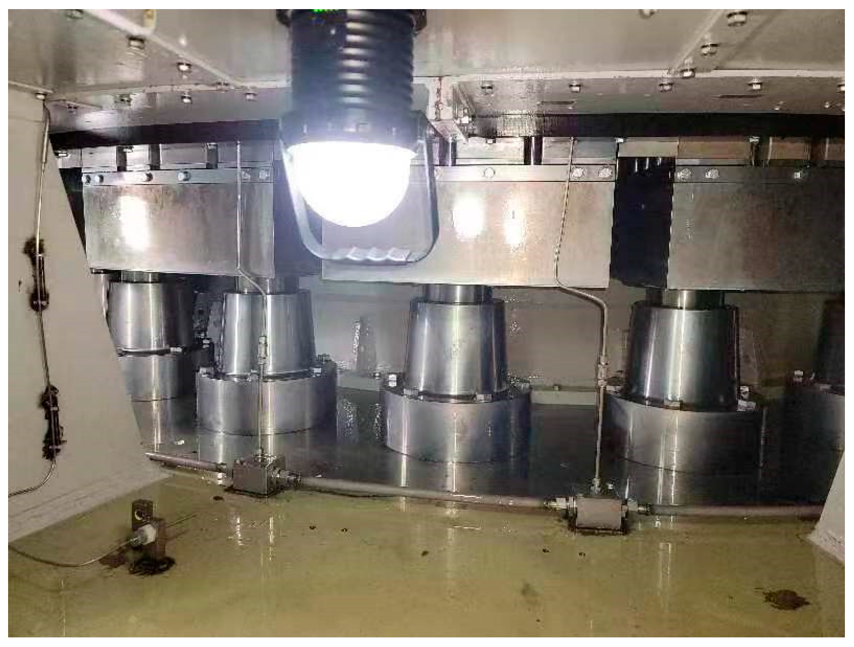
Figure 2.
Bearing model in Baihetan Power Station.

Figure 3.
Non-deviation model.

Figure 4.
Fluid domain model.

Figure 5.
Inclination .

Figure 6.
Mesh model.

Figure 7.
Mesh independence verification.

Figure 8.
Boundary condition setting.

Figure 9.
Deviation model.

Figure 10.
Streamline on collar.

Figure 11.
Pressure distribution on collar.


Figure 12.
Temperature distribution on collar.


Figure 13.
Pressure distribution on pad upper surface.

Figure 14.
Temperature distribution on pad upper surface.

Figure 15.
The variation curve of axial force F with inclination .

Figure 16.
Pressure distribution on collar under different working conditions.

Figure 17.
Temperature distribution on collar under different working conditions.

Figure 18.
Variation of axial force on bearings with deviation.


Table 1.
Parameters.
| Item | Value |
|---|---|
| Pad inner radius R1/mm | 1770 |
| Pad outer radius R2/mm | 2515 |
| Fluid domain inner radius R3/mm | 1670 |
| Fluid domain outer radius R4/mm | 3525 |
| Pad thickness H1/mm | 55 |
| Support tile thickness H2/mm | 80 |
| Tank height H3/mm | 811 |
Table 2.
The relationship between and oil film thickness.
| Inclination | Maximum Thickness/mm (Left) | Minimum Thickness/mm (Right) |
|---|---|---|
| 0.0030 | 0.1 | 0.066 |
| 0.0033 | 0.1 | 0.063 |
| 0.0036 | 0.1 | 0.059 |
| 0.0039 | 0.1 | 0.056 |
| 0.0042 | 0.1 | 0.052 |
| 0.0045 | 0.1 | 0.049 |
Table 3.
Relationship between mesh layer number and mesh number.
| Number of Oil Film Mesh Layers | Mesh Number | Axial Force /t |
|---|---|---|
| 12-layer | 204,534 | 2108.31 |
| 10-layer | 152,960 | 2057.23 |
| 7-layer | 132,155 | 1864.51 |
| 6-layer | 125,220 | 1732.93 |
| 3-layer | 104,415 | 1573.12 |
Table 4.
The oil film inclination under different working conditions.
| Conditions | Hydraulic Thrust /t | Axial Force /t | Inclination /° |
|---|---|---|---|
| Optimum operating condition | 653 | 2027 | 0.0039 |
| Minimum head condition | 786 | 1895 | 0.0038 |
| Maximum head condition | 694 | 1987 | 0.0039 |
| Rated condition | 1020 | 1660 | 0.0037 |
Disclaimer/Publisher’s Note: The statements, opinions and data contained in all publications are solely those of the individual author(s) and contributor(s) and not of MDPI and/or the editor(s). MDPI and/or the editor(s) disclaim responsibility for any injury to people or property resulting from any ideas, methods, instructions or products referred to in the content. |
© 2023 by the authors. Licensee MDPI, Basel, Switzerland. This article is an open access article distributed under the terms and conditions of the Creative Commons Attribution (CC BY) license (https://creativecommons.org/licenses/by/4.0/).
Share and Cite
MDPI and ACS Style
Ji, Z.; Shi, Y.; Da, X.; Cao, J.; Gong, Q.; Wang, Z.; Huang, X. Influence of Installation Deviation of Thrust Bearing on Oil Film Flow of 1000 MW Hydraulic Turbine Unit. Water 2023, 15, 1649. https://doi.org/10.3390/w15091649
AMA Style
Ji Z, Shi Y, Da X, Cao J, Gong Q, Wang Z, Huang X. Influence of Installation Deviation of Thrust Bearing on Oil Film Flow of 1000 MW Hydraulic Turbine Unit. Water. 2023; 15(9):1649. https://doi.org/10.3390/w15091649
Chicago/Turabian StyleJi, Zhenwei, Yishu Shi, Xinming Da, Jingwei Cao, Qijun Gong, Zhengwei Wang, and Xingxing Huang. 2023. "Influence of Installation Deviation of Thrust Bearing on Oil Film Flow of 1000 MW Hydraulic Turbine Unit" Water 15, no. 9: 1649. https://doi.org/10.3390/w15091649
Note that from the first issue of 2016, this journal uses article numbers instead of page numbers. See further details here.