

Analysis of Wave Parameters on the Uprighting Process of a Grounded and Capsized Ship
by
 ,
,
Dewei Pan
1,
Zhijie Liu
2,
Zhaoxin Zhou
1,*,
Yanan Geng
1,
Jinpeng Shang
1,
Zhen Min
3 and
Wei Zhang
3 1
School of Navigation and Shipping, Shandong Jiaotong University, Weihai 264209, China
2
Naval Architecture and Ocean Engineering College, Dalian Maritime University, Dalian 116026, China
3
China Yantai Salvage, Yantai 264099, China
*
Author to whom correspondence should be addressed.
Water 2023, 15(9), 1654; https://doi.org/10.3390/w15091654
Submission received: 21 February 2023
/
Revised: 22 March 2023
/
Accepted: 18 April 2023
/
Published: 23 April 2023
(This article belongs to the Section Hydraulics and Hydrodynamics)
Abstract
:It is a complicated task to right a capsized ship on the sea bottom because of wave load. Based on the influence of waves on stability and mechanical action, this paper constructs a wave force calculation model by the airy wave theory, and the stability and righting force models of righting a grounded and capsized ship are obtained. The uprighting process of a grounded and capsized ship is simulated by GHS software. In the process, stability and righting force are solved, and the effect of wave parameters on stability and mechanical action is studied. The result shows that when the wave phase is at its origin, the stability and the righting force can be effectively reduced. The wavelength has a significant effect on the hull stability, righting force and ground force in the range of 25 m–35 m. The change of wave height has significant influence on the stability and ground force, but the maximum ground force does not always change regularly with the wave height. Variation of the angle between the hull and the direction of the wave could significantly affect the stability, righting force, and ground force. When the encounter angle is 90°, the righting force is smaller than in other cases, and the maximum negative-going stability, the maximum righting force, and the maximum ground force values are 7.1%, 7.57%, and 3.83%, respectively, 11.7% smaller than those of still water. It is found by comparing several groups of wave parameters that a transverse wave could significantly reduce the difficulty of righting a grounded and capsized ship.
1. Introduction
With the development of the shipping economy, the density of ships at sea is increasing, but ship accidents occur more frequently, of which ship stranding accidents account for a large proportion, and the types of accidents are varied [1]. A stranded ship is a ship trapped on a rock or seabed and unable to move on its own [2]. Ship grounding accidents may lead to waterway jam, hull damage, sinking, capsizing, cargo damage, environmental pollution, or human death or injury [3,4].
A grounded ship should be salvaged as soon as possible in case of secondary accidents [5,6]. A salvage plan is needed to refloat the stranded ship. To this end, we must understand the forces and moments acting on the ship. The accuracy of the stability and force calculation directly determines the success of the salvage project. The computing work of the salvage project is large, involving a lot of tedious work, such as determining the positions and mount of the ground point, reaction force, trim angle, draft, the damage conditions of the structure, and the environment force [7].
Waves must be considered in many salvage projects. At present, many theories are used to calculate wave forces. The application scope of airy wave theory, finite amplitude theory, Stokes wave theory, solitary wave theory, and cnoidal wave theory were analyzed in terms of Ursell number by Gu and Li [8,9]. Airy wave theory is widely used in engineering to solve various practical problems. Zhang applied airy wave theory to solve the vertical wave force of a gyro-shaped buoy in a wave-power-generation device, which was used to analyze the force distribution of the buoy [10]. Airy wave theory was adopted by Wang to calculate wave force under a unidirectional wave [11].
Qiao et al. calculated the vertical wall force of a floating body with vertical porous walls. From the result, it was found that a vertical porous wall can reduce vertical wave force slightly [12]. Seung-Ho Ham et al. studied the effect of amplitude and heading angle on floating crane [13].
Mikulić et al. have found that the wave action of a grounded ship is different from a ship floating on water [14]. Zheng Huang et al. solved the vertical wave force of a grounded ship, and wave action process was obtained through the experiment [15]. Sun applied an integral iteration method to write a computer program in order to calculate the vertical wave force of ship [16]. According to the research findings of Ye et al., vertical force is induced when a submersible platform is affected by wave that is larger than the wave-free environment, which can decrease the reaction force of the bottom, and its tip-over stability is affected [17].
Wave phase angle affects the force distribution of a floating body. Zhang studied the effect of phase angle, wave-propagation direction, wave height, and wave-length on the exceeding water gesture of a floating body [18]. By simulation, the peak value of the wave force of a jacket platform corresponding to the phase angle was not varied with wave height [19]. Shao studied the relationship of phase angle and afloat condition of a trimaran, and emphasized the influence of phase deviation [20].
Field staff should well understand the effect of ground force on the floating state and stability in salvage projects. Stability should be calculated to ensure safety for salvage projects [21]. Paula C. de Sousa Bastos and Marta induced the calculation method of ground force, stability, draft, and inclination angle [22]. The characteristic of the stability of a grounded ship is that its positive-going/negative-going stability is bigger than other ships [23].
When a ship is grounded in multiple locations, the value of the ground force is determined by the weight distribution, buoyancy distribution, and positions of grounding points [24]. The mechanical distribution of the hull is also affected by the structure [25]. Pan deduced the calculation method for ground force, and GHS software was used to solve the ground force during the uprighting process [26,27,28].
It is a complicated task to right a capsized ship on the sea bottom because of wave load. Based on the study of the impact of waves on a ship, this paper deduced the calculation method of wave force. In accordance with the actual conditions of the salvage project, GHS software was applied to simulate the uprighting process of a grounded and capsized ship. The effects of four kinds of wave parameters on the uprighting process were compared. We hope that practitioners pay enough attention to the wave parameters.
2. Theoretical Calculation
2.1. Wave force Calculation
In an actual project, due to the limitations of the salvage equipment, normal salvage work requires that the wave height should not exceed 1.5 m. The depth of the water around a grounded ship is shallow, so the salvage project should be processed in a low sea state. Thus, this paper deduced the calculation method of the wave force based on airy wave theory, which is commonly used in practical projects.
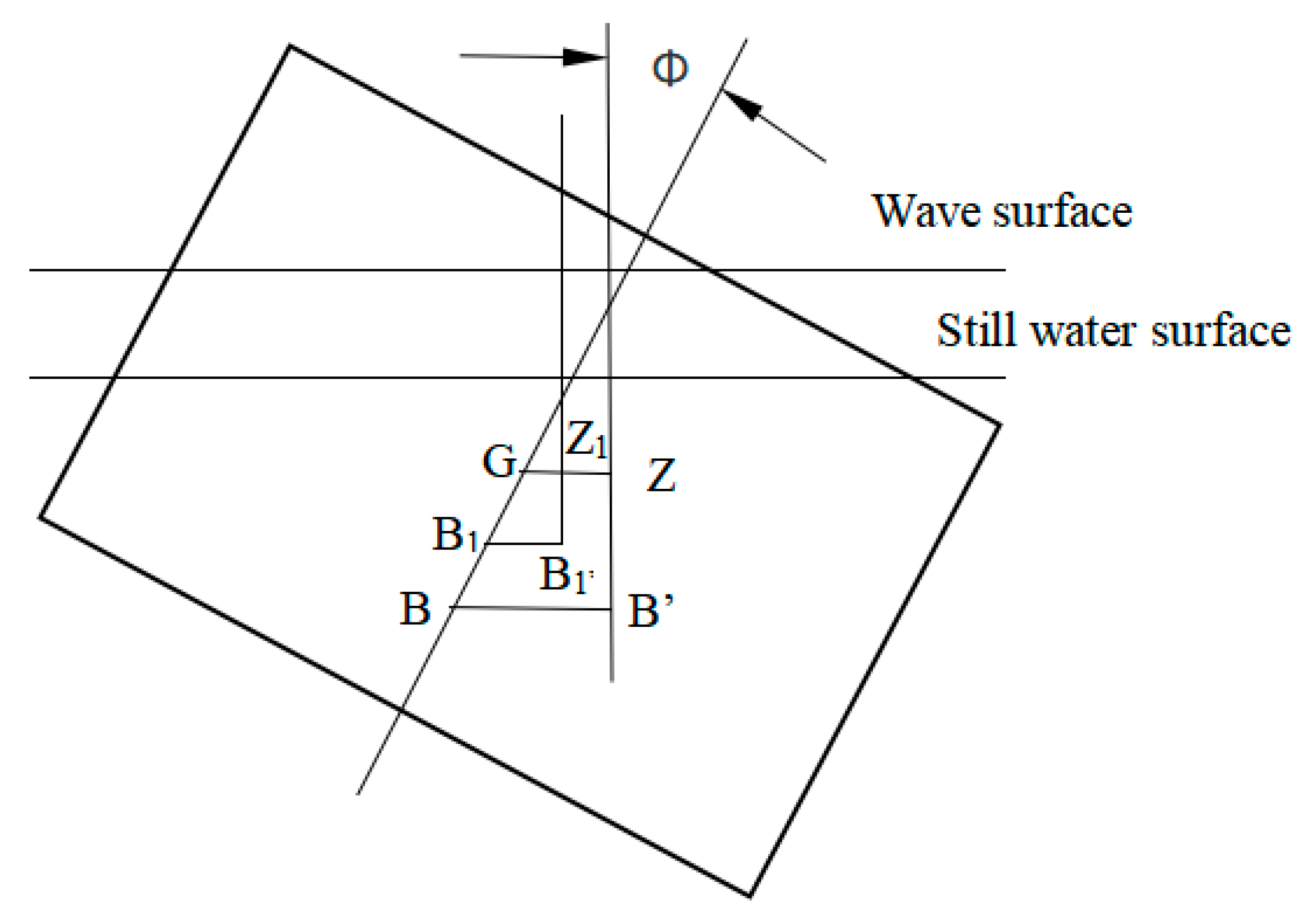
Let buoyancy center of the hull in still water be B and the gravity center G. The righting arm of the ship is when the heeling angle is , then the buoyancy center of the hull is B′, as shown in Figure 1.
In the following waves, as the volume shape of the underwater part of the hull changes, the position of the buoyancy center also changes. It can be assumed that the floating center moves from B to B1 when the ship is floating. When the heel angle is B1′, the static stability arm in the following wave is obtained.
Potential function provides the groundwork of airy wave theory, and it is used to study the wave movement. This assumes that the wave is regarded as a kind of ideal liquid, being uncompressed, non-adhesive, and irrotational. Considering the gravitational potential energy, this section studies the calculation method of wave force.
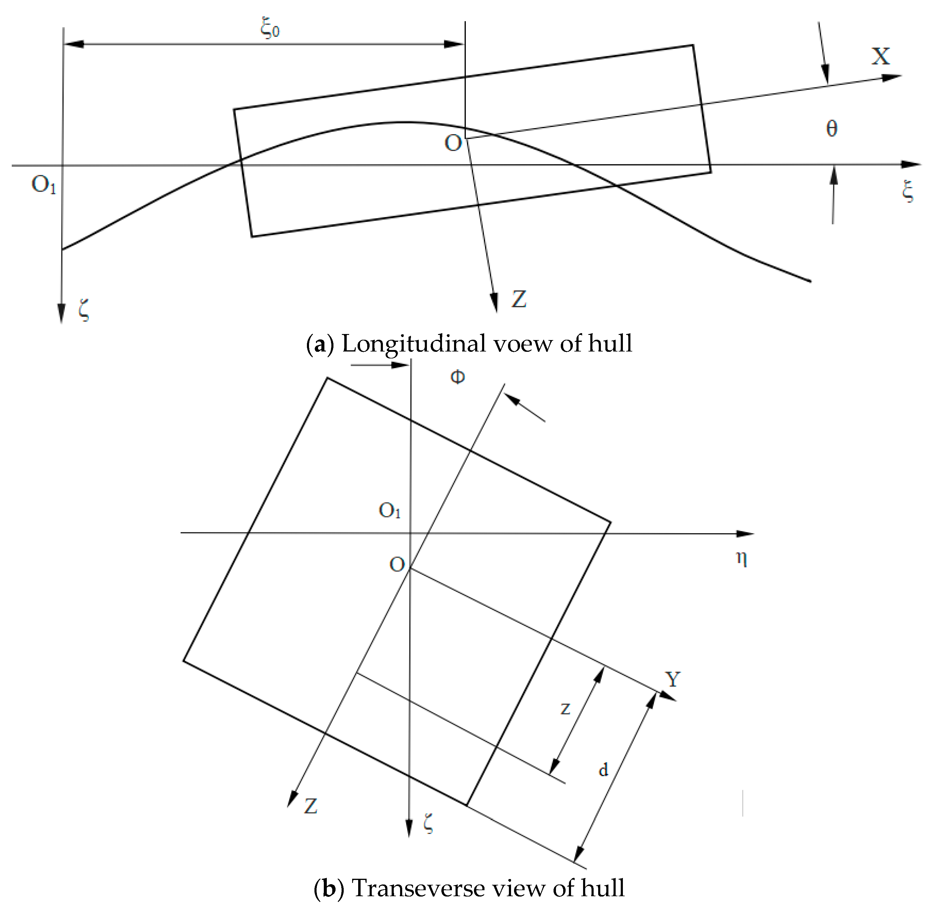
It can be assumed that the amplitude is , wave number is , and wave velocity is . In Figure 2, waveform at time of the fixed-coordinate system is obtained [29].
Pressure at any point in a wave field can be solved by Bernoulli equation [30]:
where is the density of water, and is gravitational acceleration.
Thus, pressure gradient in water depth direction is solved.
To simplify the problem, pressure gradient at depth of represents the pressure gradient on the ship surface.
Here, is the draft of the ship.
It can be seen from the above formula that variation of the pressure gradient induced by wave orbital motion can be represented by variation of water density.
Let be the distance between amidship and the wave trough. Thus, , and water density of , which is m off the amidship, is obtained.
Let be the weight of the ship. The righting moment of the ship in the following waves is obtained when ship’s heel angle is .
Here, is the wave moment, is the righting arm, and is the distance between O and the center of gravity.
In (8), the first term is the shape-restoring moment, and the second term is the restoring moment induced by weight.
As Figure 2 shows, is the half-width of the waterline at a random position , and is the draft under upright floating conditions in still water. is the left draft. is the right draft. Thus, can be calculated.
It follows from the above that if and are known, the righting moment can be solved by (8) and (9).
and are unknown variables. According to the condition of static equilibrium of hydrostatic and posture, and can be solved by the method of perturbation.
The section area of the underwater part in waves , which is m off the amidship, is obtained. The force condition of the ship satisfies the following equation.
In Figure 2, can be represented by the following formula.
Let the section area of the ship underwater in upright floating conditions be represented by the following formula.
Here,
Formulas (10) and (11) combine into Formula (14). In order to obtain the following formulas, second-order small quantities are omitted.
and can be determined by solving Formulas (16) and (17).
The vertical wave force of an arbitrarily shaped body can be represented by the following integral formula [31].
Here, is the undisturbed pressure of any point on the surface of an object. is the angle between wave pressure vector and horizontal axes. is vertical diffraction coefficient.
2.2. Righting Force Calculation
Based on the Reference [32], Equation (19) is obtained:
Here, , , and are the moments of gravity, buoyancy, righting force and vertical wave force resolved into three components along the coordinate axes.
The relationship between , , is represented by:
The static equilibrium equation of gravity , buoyancy force , ground reaction , vertical wave force and righting force can be obtained.
Then, the mechanical model of uprighting is established.
3. Simulation Calculation
3.1. Simulation Calculation Method
3.1.1. Ground Force
At present, many computer programs can calculate the ground force, but they are based on traditional methods of calculation, which belong to manual calculation. In the traditional calculation process, the negative gravity method is often used to solve the ground force; that is, when the position of the ground point is close to the center of the ground area or below the center of buoyancy, the calculation result is accurate. Generally, the value of the ground force changes nonlinearly when the variation of ground point position.
GHS software is the only software that can quickly and accurately calculate the ground force. It can not only analyze the ground force of the stranded ship when it enters the mud, but also calculate the ground force when it does not enter the mud.
GHS can accurately evaluate the stability and strength of the grounded ship by considering the ground force at each ground point as the point buoyancy. After setting the initial ground condition, the grounding condition of the ship can be obtained. The approach of GHS software in calculating the ground force of the ship when it enters the mud is as follows. Similarly to the buoyancy calculation of the ship in normal operation, it is considered that the ground force of the stranded ship is the buoyancy of some liquid on the ship at the ground point; that is, the soil in the ground point area is considered as liquid and its density is very high. When the ship is grounded, there is a common point between the hull and the seabed, that is, the ground point. When the depth of the ship entering the mud tends to increase, it will be prevented from further sinking by the strong buoyancy generated by the ground area.
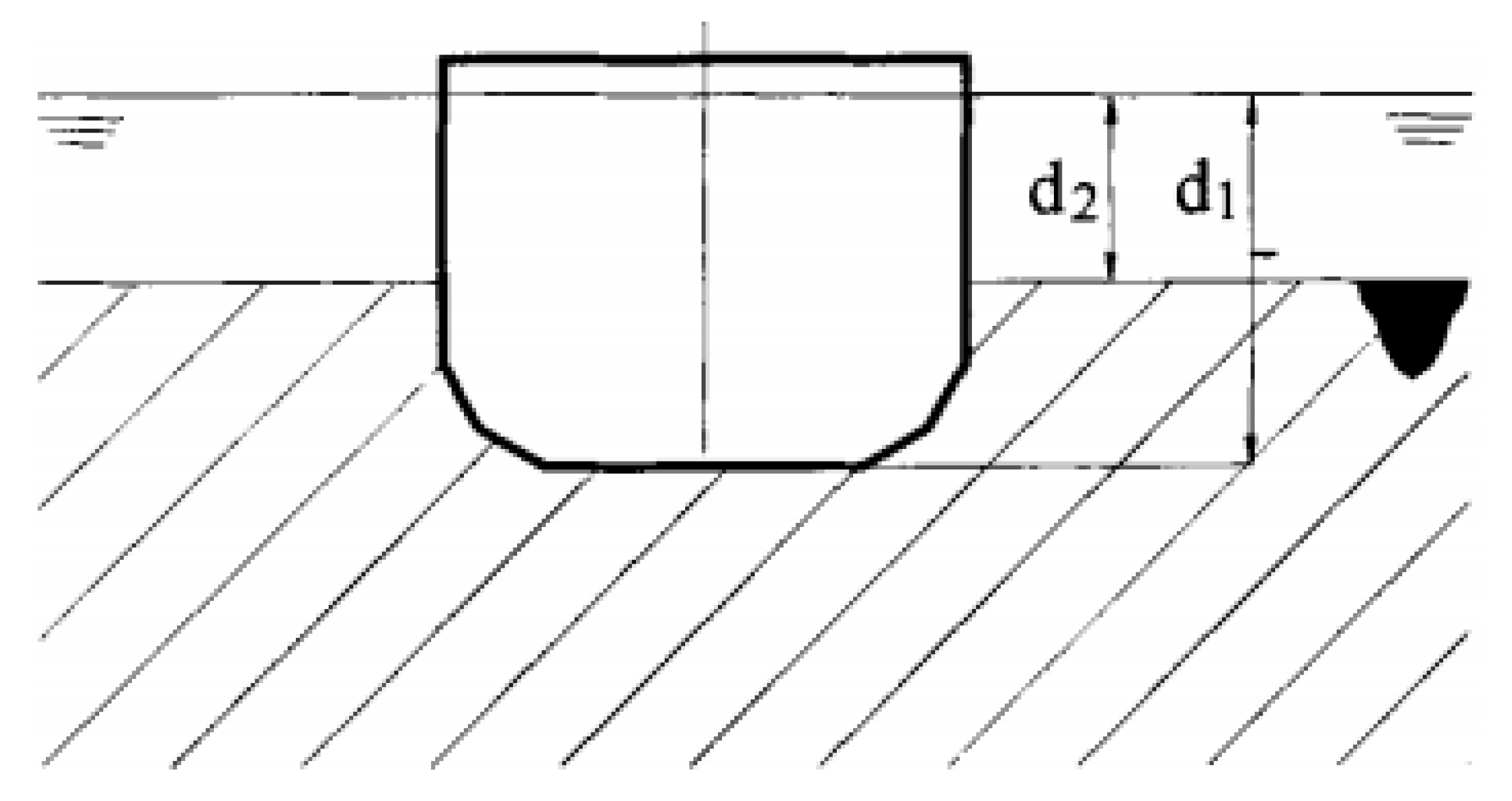
Similarly to the relationship between the size of the ship’s buoyancy and the draft depth, the calculation of the ground force is related to the depth of the hull in the mud. The formula is [33]:
There, is the depth of ground point, is the depth of ground area, and is a constant. The paramenters in (23) are shown in the Figure 3.
3.1.2. Wave Force Calculation
GHS allows the user to define the wave waveform and add it to the horizontal water surface. Waves are mainly used for the calculation of longitudinal strength. If the waveform has been defined, waves will be included in other calculations. WAVE command is used to define the waveform. There are 3 elements used for defining the waveform, namely phase, wavelength, and wave height. If default, GHS assumes that the wavelength is equal to the length between perpendiculars, and the wave height is 1/20 of the wavelength, but the phase angle must be specified.
When the phase parameter phase is 0°, there is a peak above the origin (vertically projected onto the reference plane). As the phase increases, the peak moves forward in the direction of the wave according to the encounter angle. The peak starts from the initial phase angle every 360°, and the trough is at ±180° of the peak. For example, if the encounter angle is 0°, the wave moves toward the stern, and when the peak is in the after-perpendicular, the phase is 180°.
3.2. Establishment of the Ship Model
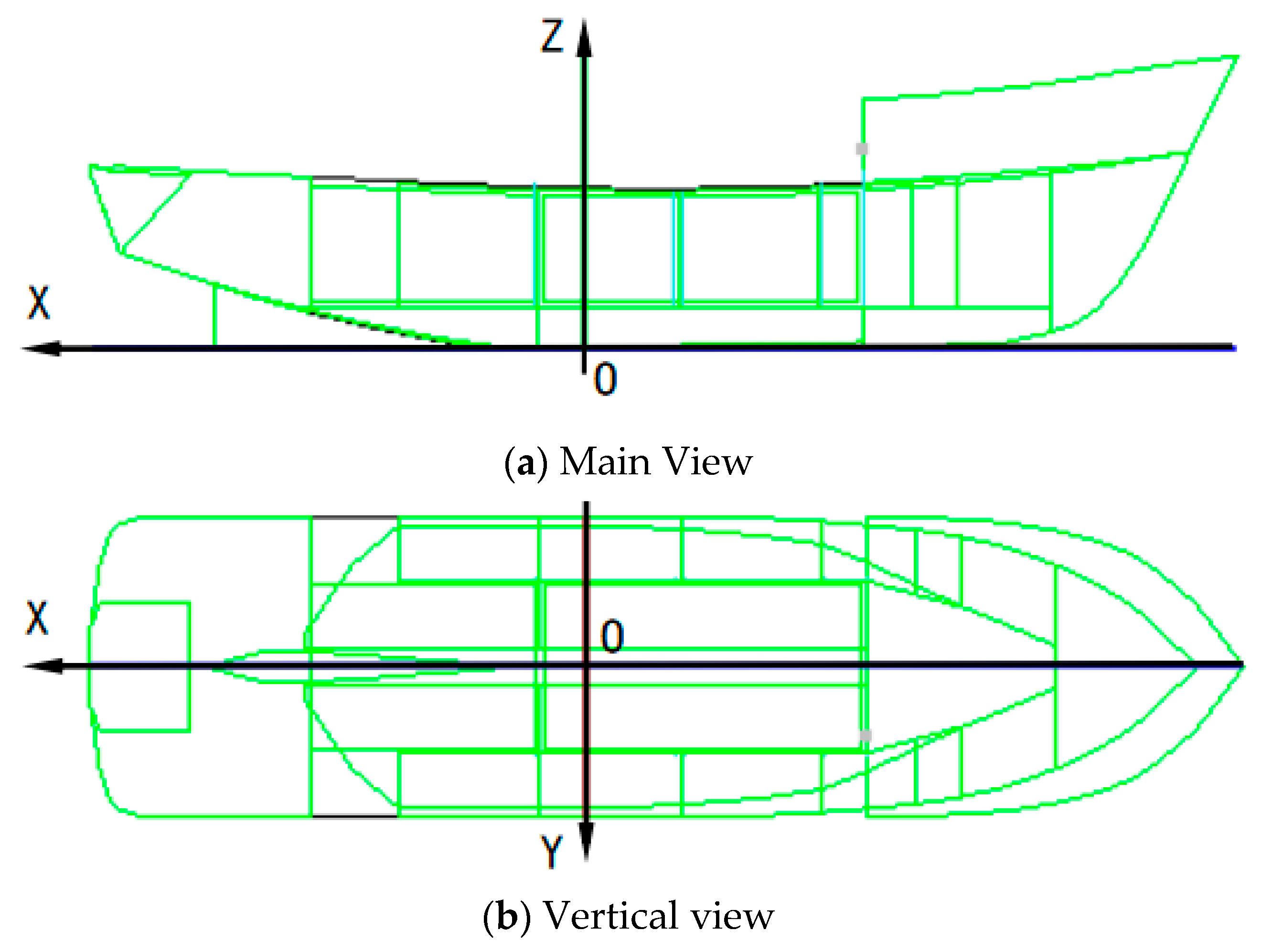
Using the ship in Figure 4 as an example, the origin crosses the area of the base plane, the midship section, and the longitudinal mid-section, which is 40.81 m from the stern. The axis direction is as follows: X is the intersection of the base plane and the longitudinal midsection; the stern represents the positive direction. Y is the intersection of the base plane and the midship section; the starboard represents the positive direction. Z is the intersection of the longitudinal mid-section and the midship section; the positive direction is over the base plane. Table 1 shows the ship’s principal dimensions.
3.3. Simulation Scheme
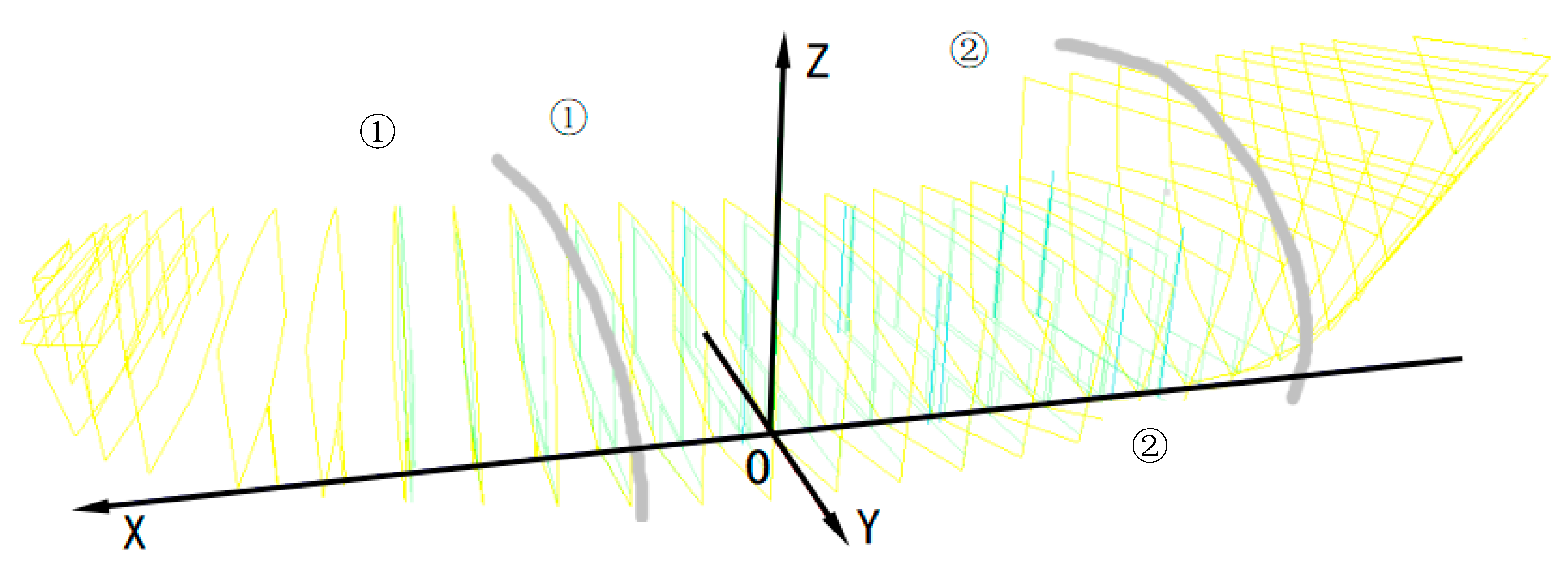
After defining the uprighting method, the influence of the hull attitude on the uprighting work should be considered in designing the positions of the ground point, the direction of the righting force and the position of the action points of the righting force. The coordinates of the ground points are (−27.00, 8.42, 4.36) and (−23.10, −12.26, 20.61). Righting force is set in the 2 sections, longitudinal coordinate is 23.10 and −30.80, and the coordinates of the action points of the righting force are (23.10, 12.25, 23.55), (23.10, 0.00, 23.732), (23.10, −12.25, 23.55), (−30.80, −12.07, 21.16), (−30.80, 0, 23.732), and (−30.80, 12.07, 21.16). In Figure 5, ① and ② indicate the positions of the pulling cables. The direction of the pulling force at any point is vertically upward. In the process of simulation, righting force changes along with the variation of heel angle. The changes of floating state, stability and ground force can be obtained. If the force at any position exceeds the allowable value, the simulation program stops.
4. Simulation Calculation and Analysis
Due to the influence of water depth, water bottom, bank shape, and wind, wave parameters will change, which will further cause the change in hull buoyancy, stability, and mechanical distribution, making it more difficult to right the capsized ship. In consideration of the experience of [34], this paper applied GHS software to study the influence of wave phase angle, wavelength, wave height, and encounter angle on the uprighting process of a grounded and capsized fishing vessel. The longitudinal coordinates of the cross section of the ground point were −27.00, −23.10, 23.10, and 40.81, respectively. The results are expected to provide a data reference for salvaging large and medium-sized grounded and capsized fishing vessels.
4.1. The Effect of Phase Angle on the Uprighting Process
Variation of the wave phase angle leads to changes in the hull buoyancy distribution. In this section, the righting process of a grounded and capsized ship was simulated under no wave (case P1), wave phase at 0° (case P2), wave phase at 90° (case P3), and wave phase at −90° (case P4). The wave peaks of P2, P3, and P4 were at the middle of the first half of the hull, the middle of the hull, and the middle of the second half of the hull, respectively; the wavelength was 30 m, and the encounter angle was 0°.
4.1.1. Righting Arm
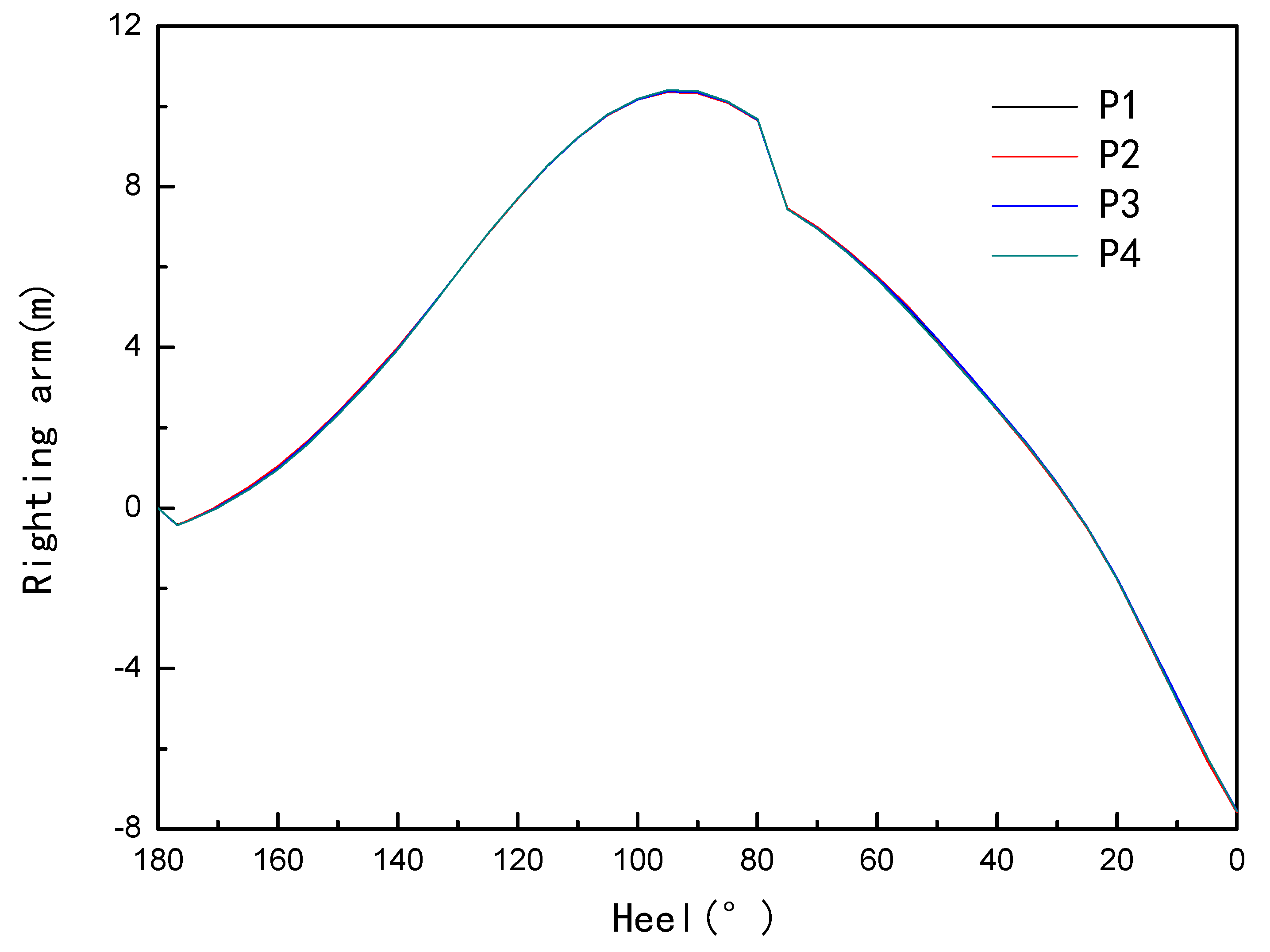
Figure 6 shows the stability curves of the capsized ship. In this section, the stability curves were obviously different from the stability curve of the capsized ship floating on the water surface, which was similar to the stability curves of a damaged and capsized ship.
The stability change trend of the hull in the four working conditions was consistent, and the righting force needed to be applied in the early and late stages of the righting process, especially in the late stage. In the middle of the righting process, the hull automatically rotated forward under the action of its own stability. The maximum stability values of the four conditions had little difference. The maximum positive stability arm values were 10.384 m, 10.372 m, 10.405 m, 10.367 m, and the maximum negative stability arm values were −7.584 m, −7.546 m, −7.561 m, −7.583 m. The calculation results showed that the stability arm values of the ship under these conditions were relatively small, but the maximum recovery moment difference was close to 200 kN.m. When the phase angle was 90°, the maximum positive stability was higher than that of the non-wave condition, which was obviously different from the stability of the floating body floating on the still water surface. Although the added value of the stability was small, it could provide a reference for salvage projects involving grounded ships in waves. In particular, many salvage projects are limited to the actual calculation level, and the salvage scheme design is guided by the static calculation results. When the ship encounters a wave phase of −90°, the wave acts on the bow. When the hull returns to the equilibrium position, the maximum negative stability arm is close to the maximum negative stability arm in the no-wave environment, and the wave effect can be ignored.
4.1.2. Righting Force
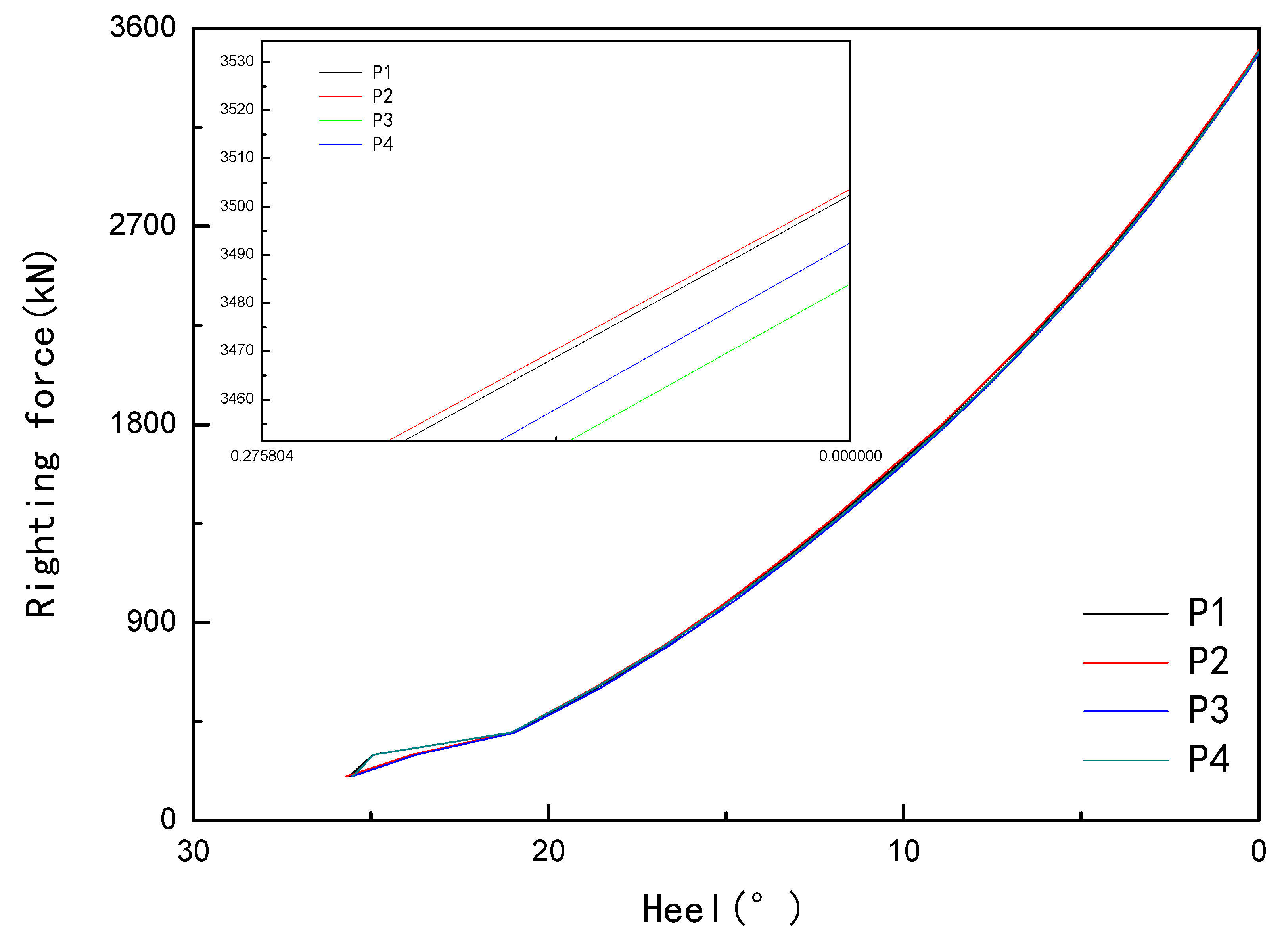
As shown in Figure 7, this section only gives the curves of the righting force in the later stages of the uprighting process. It can be seen that the righting force was increasing, and the hull needed a large righting force in the equilibrium position. The maximum righting force of the four conditions were 3502.5 kN, 3503.5 kN, 3484.5 kN, and 3492.5 kN. Under the action of waves, the wave peak had the greatest influence on the stability of the hull at the origin of the hull, and the required righting force was the smallest. Then, the phase change caused the change in the mechanical distribution of the hull, which inevitably led to a change in the ground force. There should be a certain margin in the uprighting process, and the rotation speed of the capsized hull should be strictly controlled to ensure the safety of the salvage project.
4.1.3. Ground Force
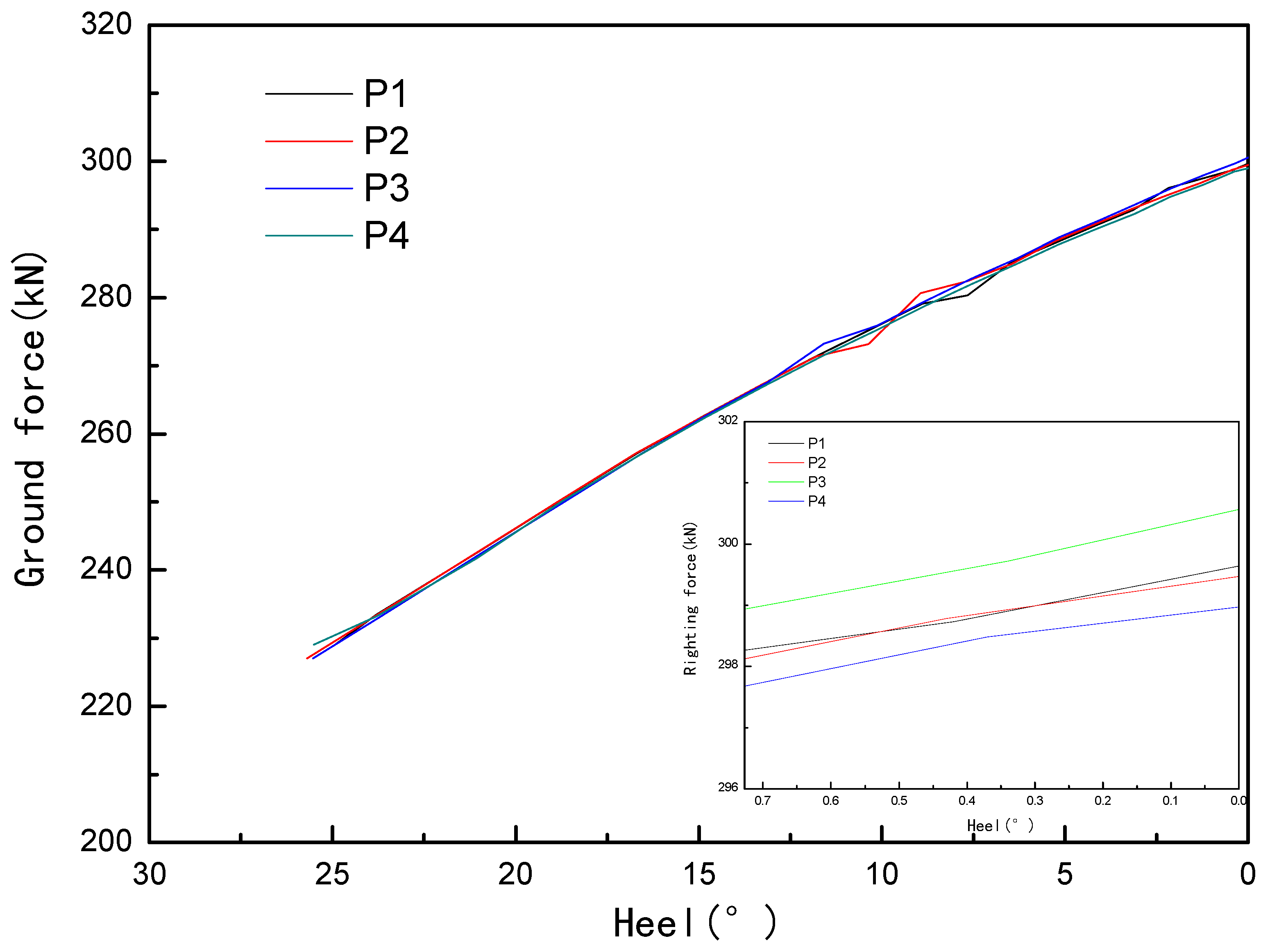
In an uprighting process, the position of the ground point and the ground force changes continuously, and the ground force even changes significantly. Through simulation (Figure 8 and Figure 9), it was found that the ground force was small in the four sections of the initial state, while it was stable in two sections (longitudinal coordinates are −27 m and 23.1 m) in the later stage of the process, and the ground force continued to increase.
When the ground point in the section had a longitudinal coordinate of −27 m, although the change trend of the four working conditions was the same, the increase in the P3 ground force was relatively large, which was due to the buoyancy increment relative to the peak. The buoyancy increment caused by the shrinkage of the hull line at the peak of the P4 working condition was small. Similarly, the ground point was in the section with the longitudinal coordinate of −23.1 m, and the ground force of P3 was relatively small. The change in the wave crest position not only changed the buoyancy distribution of the hull, but also changed the value of the ground force, thus changing the load distribution of the hull.
Through the comparison of the various cases, it can be seen that wave phase had a certain effect on the ground force. Comparing the wave case with the waveless case, it was found that in the process of uprighting, the ground point was in the section with the longitudinal coordinate of −27 m, and the maximum ground force difference between the two cases was 26.5 kN; the maximum difference between the two cases was 66.3 kN when the ground point was at the cross-section, with a longitudinal coordinate of −23.1 m.
4.2. The Effect of Wavelength on the Uprighting Process
Variation of wave wavelength causes changes in the hull buoyancy distribution. This section simulated the righting process of a grounded and capsized ship in the waveless condition (case L1), with wavelengths of 25 m (case L2), 30 m (case L3), and 35 m (case L4). L2, L3, and L4 were in the following wave state: the phase at 0°, the wave height at 1.5 m, and the encounter angle at 0°.
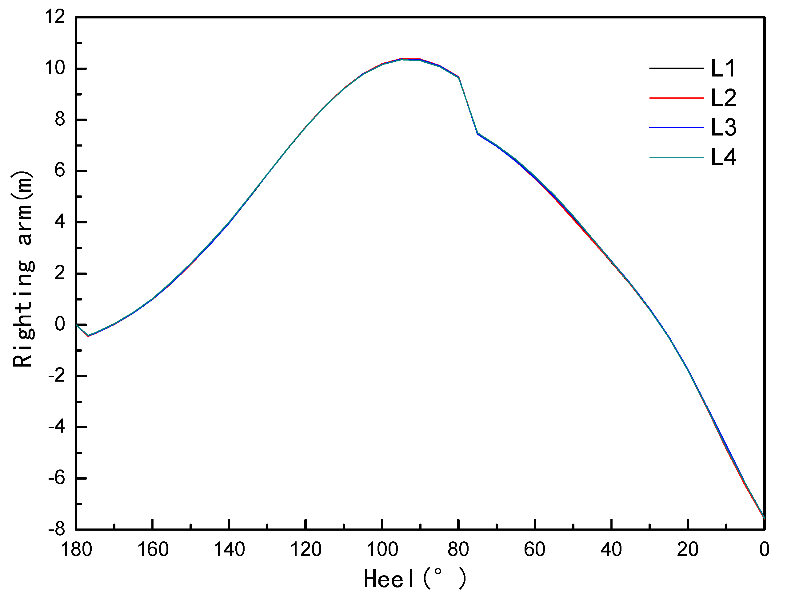
4.2.1. Righting Arm
Figure 10 shows the stability curves of the grounded and capsized hull in each working condition. When the heel angle was 0°, the corresponding maximum negative righting arm values were −7.584 m, −7.577 m, −7.546 m, and −7.537 m. The stability arm values of these working conditions were slightly different. As the wavelength increased, the stability of the ship decreased. Compared with the previous section, the maximum negative stability value was slightly lower. Staff should pay attention to the actual work of the wavelength on the impact of salvage work.
4.2.2. Righting Force
Figure 11 shows the righting force curves of the grounded and capsized hull in each working case.
The maximum righting forces required for the four working conditions was 3502.50 kN, 3501.56 kN, 3484.50 kN, and 3488.05 kN, respectively. Compared with 4.3.2, the righting force values were slightly reduced.
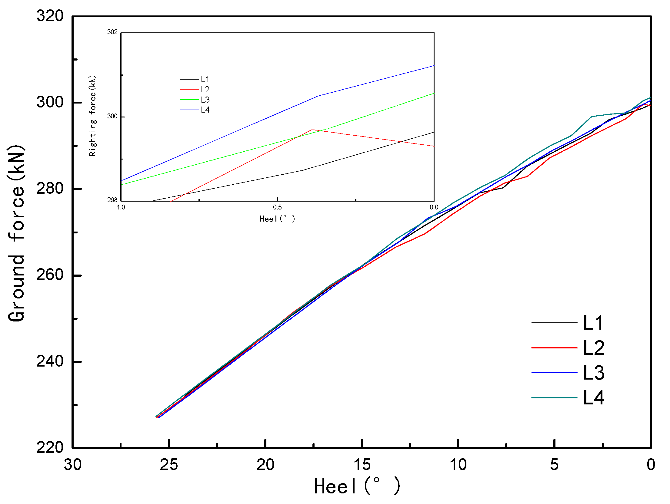
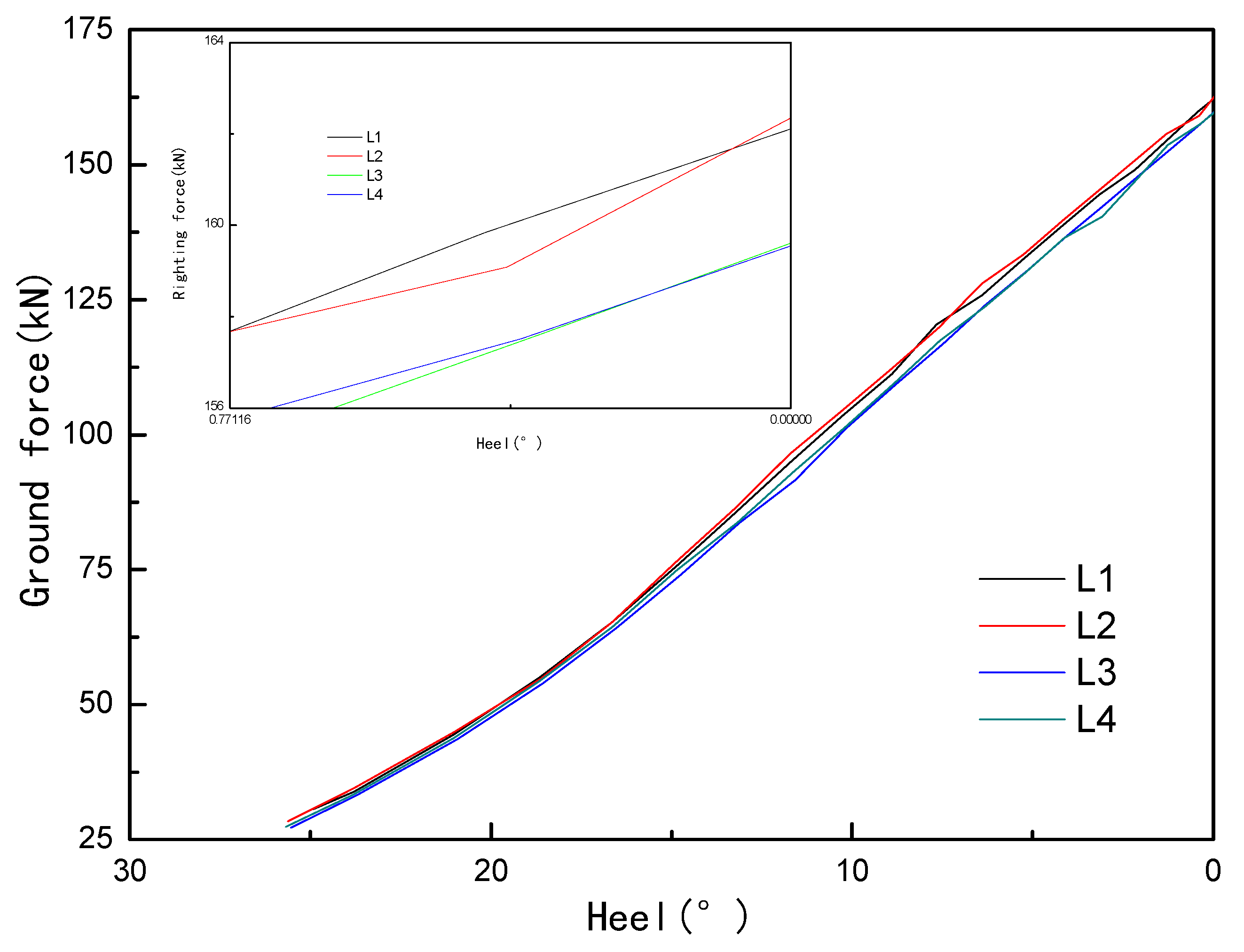
4.2.3. Ground Force
It is evident from Figure 12 and Figure 13 that although the change trend of the ground force on the two sections was the same, the maximum ground force value in each section was similar, and the ground force continued to increase when it was stably situated in the two sections (longitudinal coordinates are −27 m and 23.1 m) in the later stage of uprighting. The maximum ground force increased with the increase in wavelength when the longitudinal coordinate was −27 m, and the maximum ground force was relatively small when there was no wave. The maximum ground force was small when the longitudinal coordinate was 23.1 m, and decreased with the increase in wavelength. During the uprighting process, the maximum ground force of L3 and L4 had a small difference.
4.3. The Effect of Wave Height on the Uprighting Process
Many literature studies have found the influence of wave height on hull attitude. This section simulated the righting process of a grounded and capsized ship in the absence of waveless (case H1), wave heights of 0.5 m (case H2), 1 m (case H3), and 1.5 m (case H4). When H2, H3, and H4 were in the state of following waves, the phase was 0°, the wavelength was 30 m, and the encounter angle was 0°.
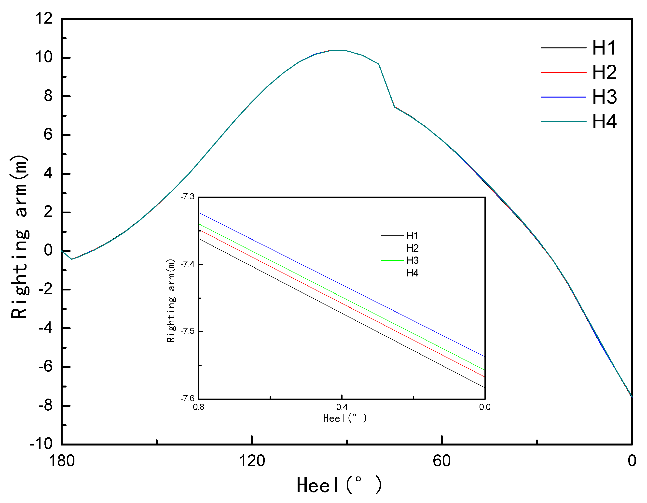
4.3.1. Righting Arm
As shown in Figure 14, the stability arm values corresponding to the equilibrium position of the hull were −7.58 m, −7.56 m, −7.55 m, −5.52 m, and the stability arm values decreased obviously with the increase in wave height.
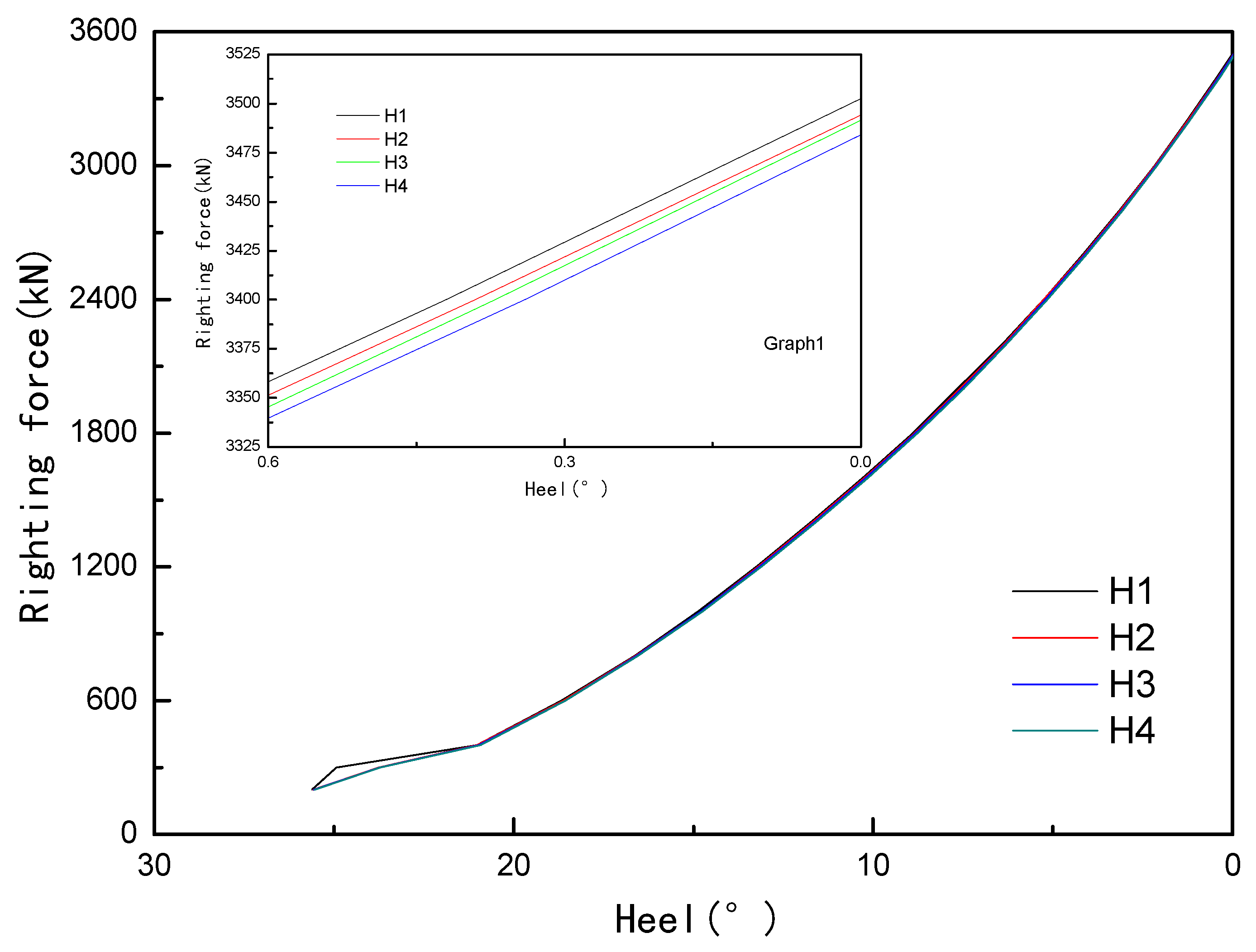
4.3.2. Righting Force
As shown in Figure 15, the maximum righting force of each case was 3502.5 kN, 3493.79 kN, 3491.71 kN, and 3482.79 kN, respectively. The maximum righting force decreased with the increase in wave height. From the stability curves and the righting force curves, it is evident that when the hull was close to the equilibrium position, the position between the curves of each working condition corresponded to it.
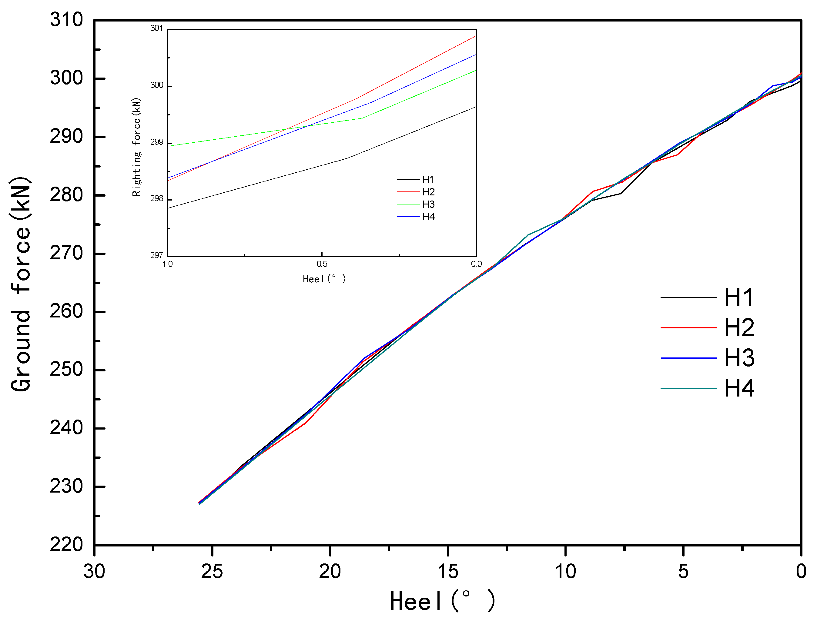
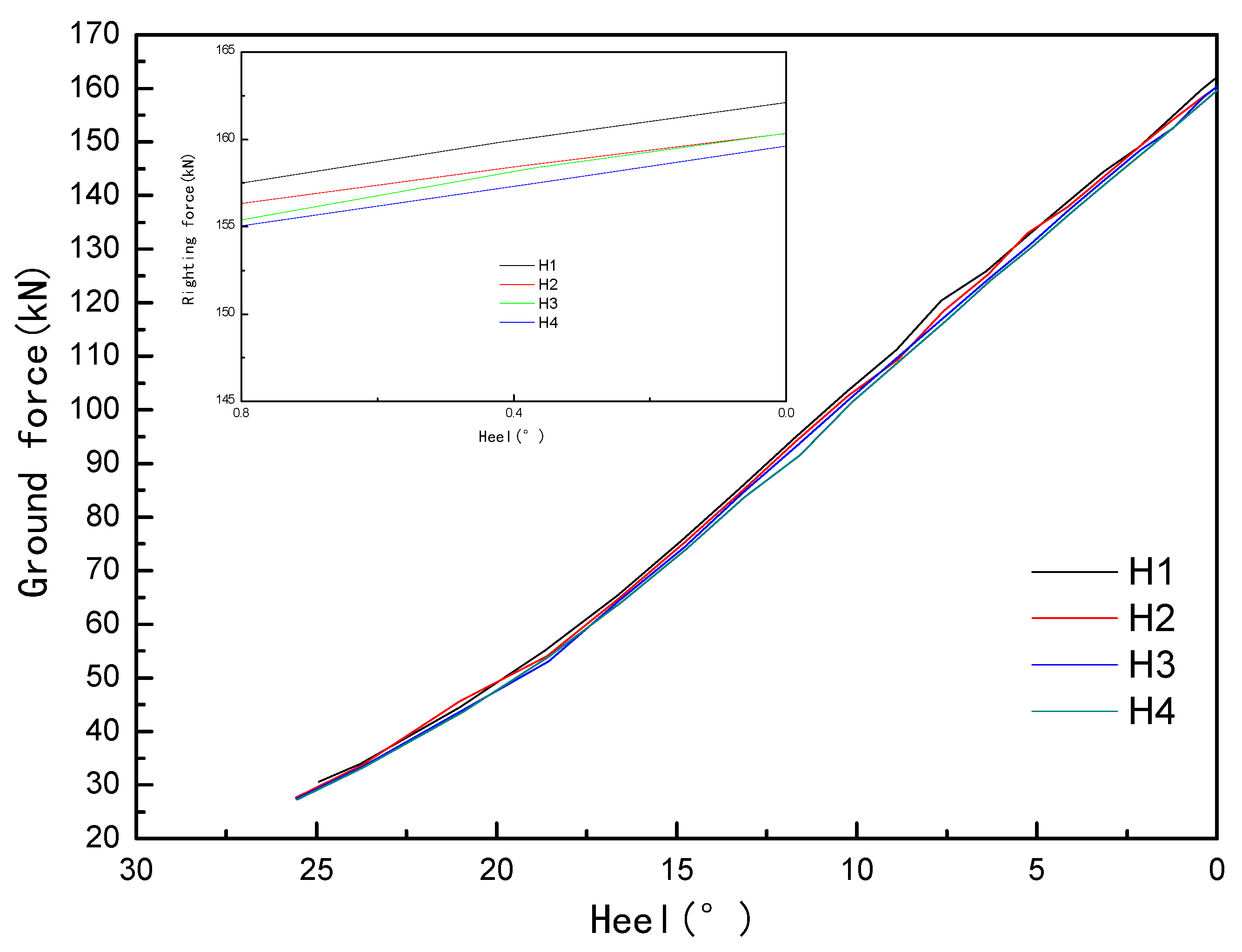
4.3.3. Ground Force
As shown in Figure 16 and Figure 17, the longitudinal coordinate of the hull section was −27, and the maximum ground force appeared in the equilibrium position, although the righting force in each working condition fluctuated slightly with the uprighting process, which had little effect on the whole righting process. The longitudinal coordinate of the hull section was 23.1, and the maximum ground force of the hull in still water and wave was quite different, indicating that the wave height had a great influence on the buoyancy distribution of the hull. In the two sections, the maximum ground force of H2 was relatively small.
4.4. The Effect of Encounter Angle on the Uprighting Process
Many literature studies have found the influence of the encounter angle on the hull attitude. In this section, the uprighting process of a grounded and capsized ship was simulated under the conditions of no wave (case E1), encounter angle at 90° (case E2), encounter angle at 180° (case E3), and encounter angle at 270° (case E4). The phase was 0°, the wavelength was 30 m, and the wave height was 1.5 m.
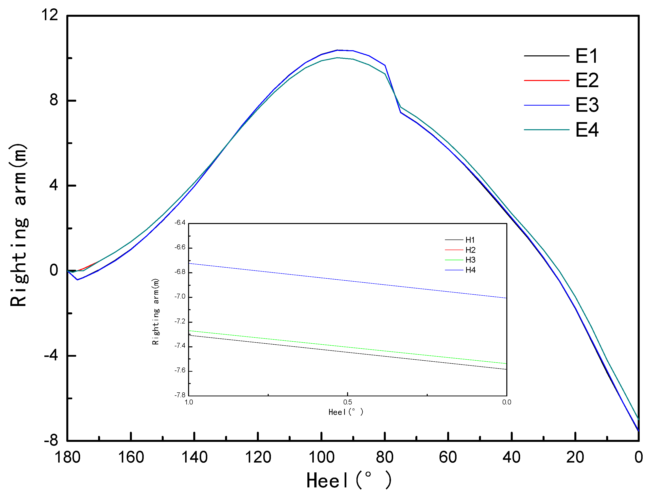
4.4.1. Righting Arm
As shown in Figure 18, the stability values of E2 and E4 were greater, and the difference between the two was almost negligible. The left and right waves of the hull had a great influence on the stability of the hull. The maximum negative stability values of E1 and E3 were similar, and the stern waves of E3 had little effect on stability. The calculation results show that the maximum stability value could be reduced by 7.1% under wave conditions.
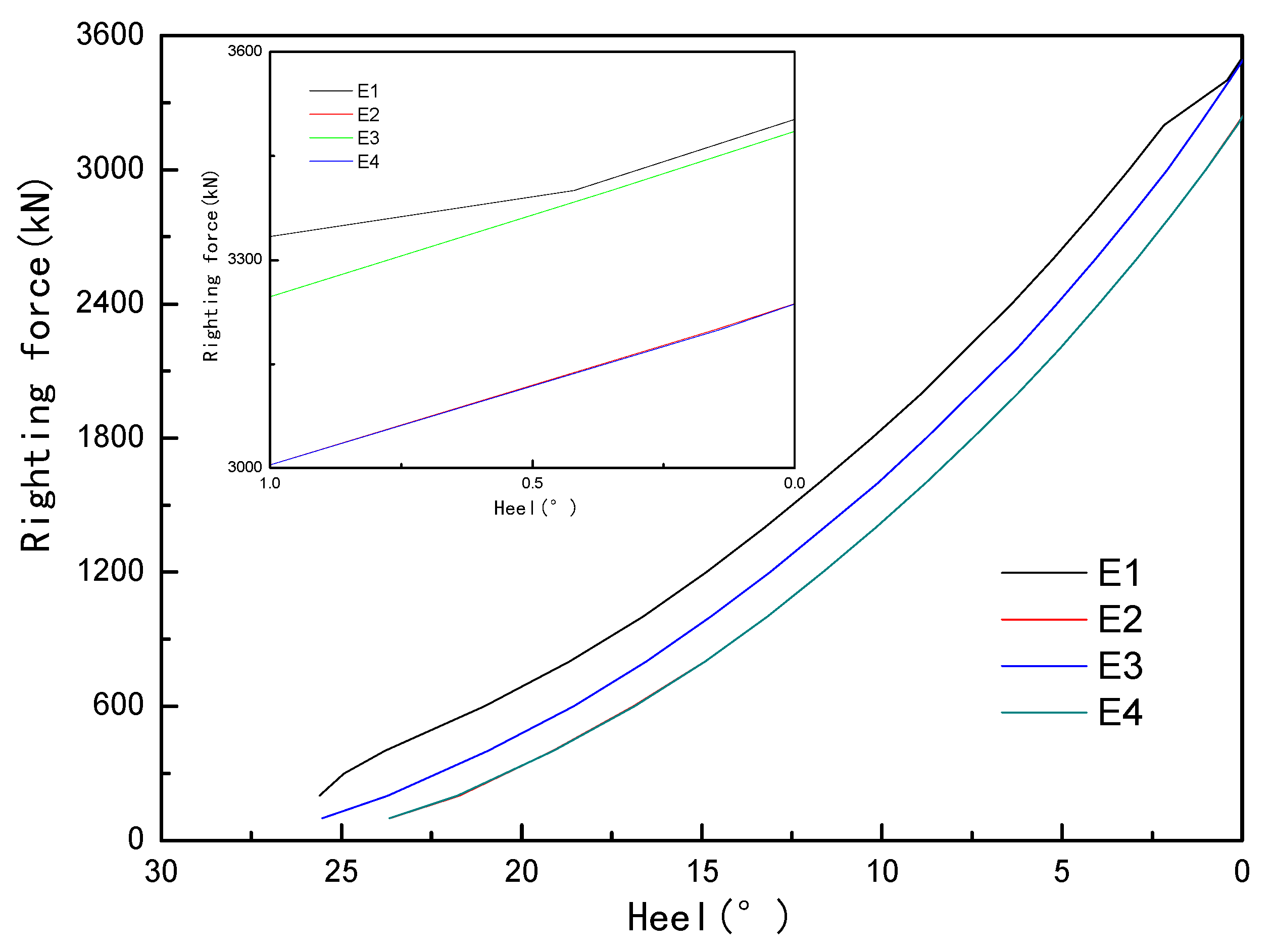
4.4.2. Righting Force
Figure 19 shows the righting force curves of the grounded and capsized hull in each working case.
The maximum righting forces of the four working conditions were 3502.5 kN, 3237.53 kN, 3487.30 kN, and 3238.18 kN, respectively. The maximum righting forces of E1 and E3 conditions were much larger than those in E2 and E4 conditions. Compared with the wave-free environment, close to the equilibrium position of the hull, the E3 condition had little effect on the maximum righting force; that is, close to the equilibrium position the wave action was reduced. During the uprighting process, the righting force of E2 and E4 conditions were similar, and the maximum righting force was also small.
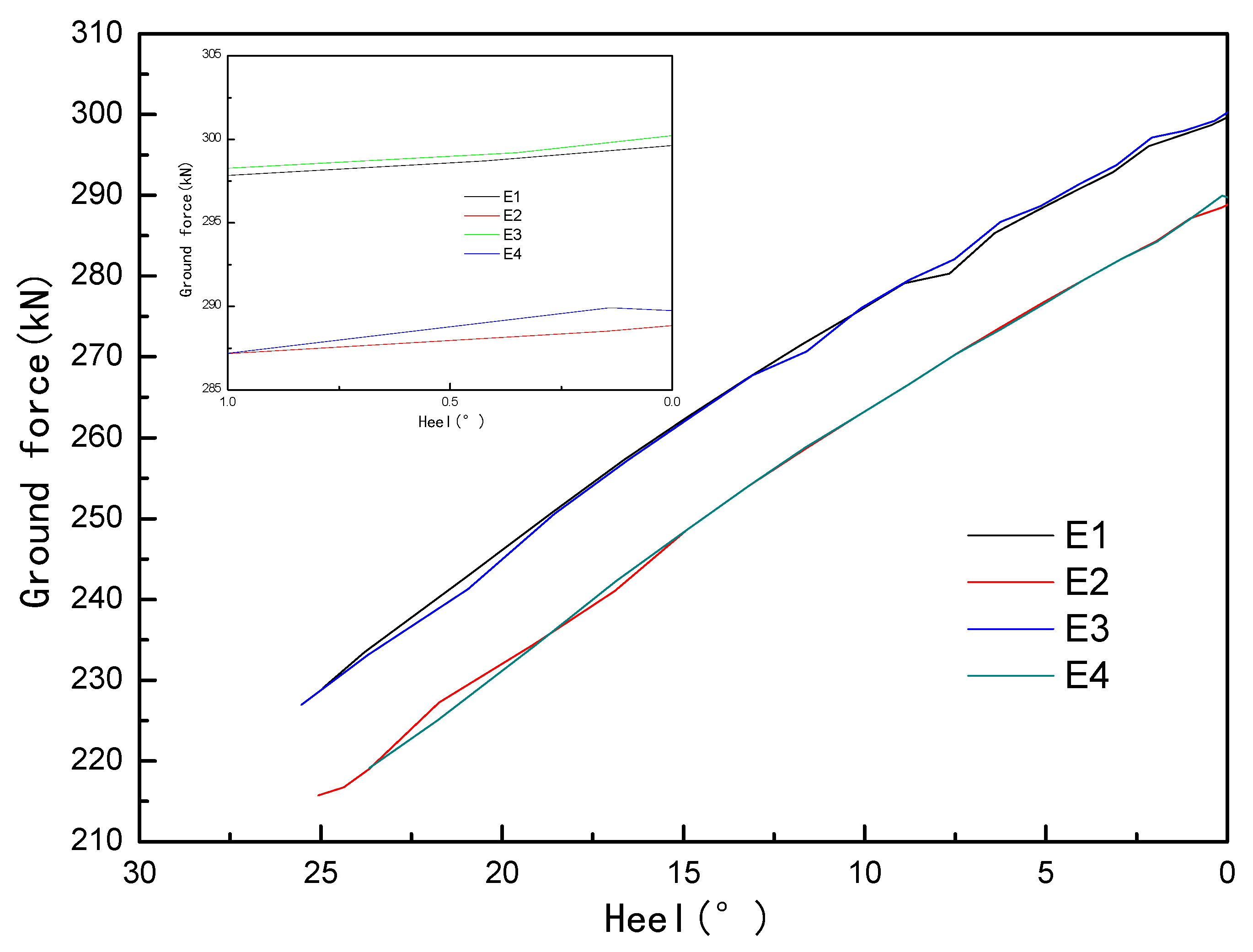
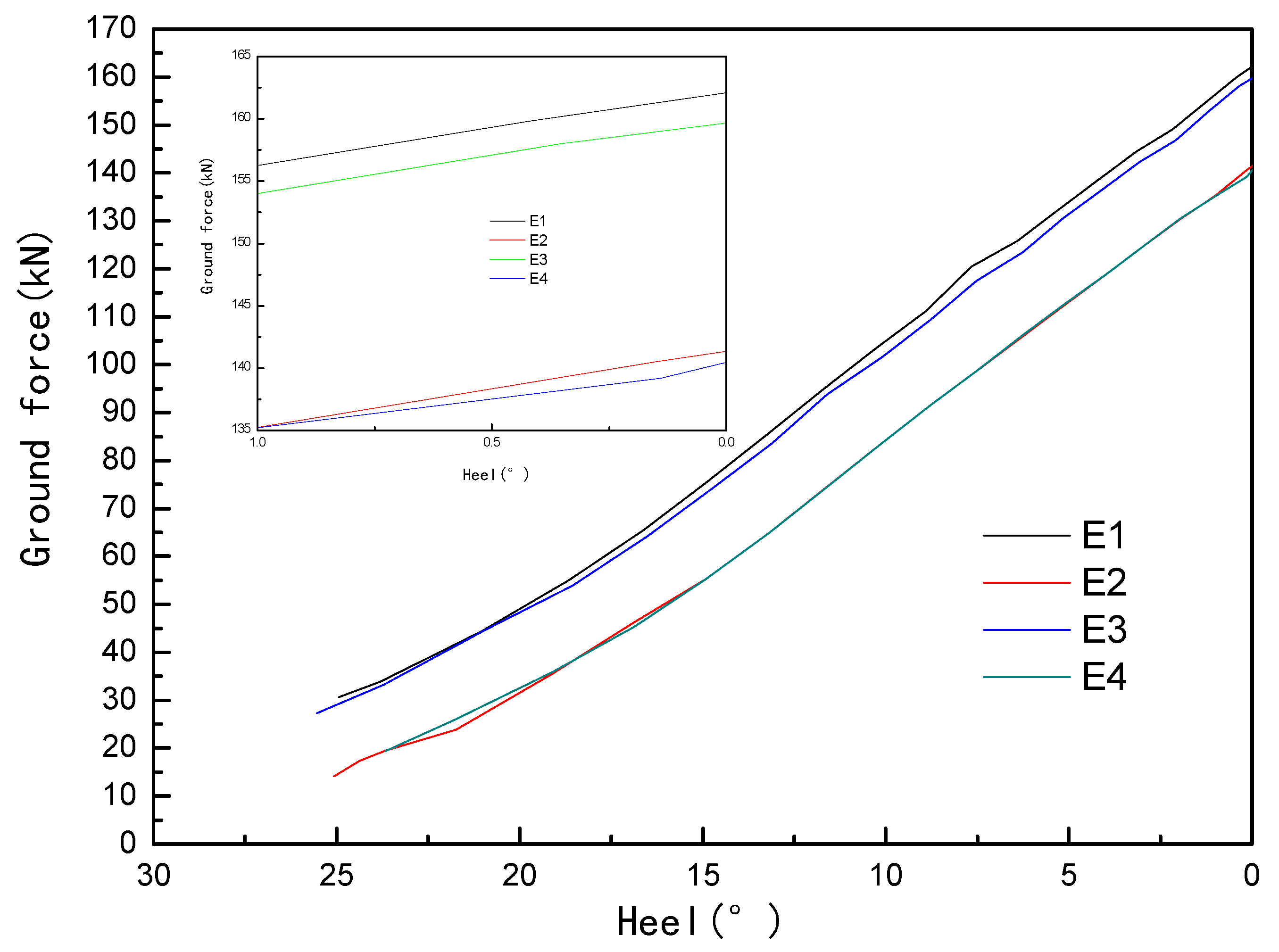
4.4.3. Ground Force
It can be seen from Figure 20 and Figure 21 that the longitudinal coordinate of the hull section was 23.1, and the difference between the ground force of E1 and E3 conditions was obvious, which was meaningful for the hull strength analysis. There was a relatively obvious gap between the maximum ground force values of E2 and E4 conditions, which was different from the calculation results of other two conditions.
5. Discussion
The change of wave phase had little effect on the stability of the overturned ship, but had a certain effect on the righting force and the ground force. For this grounded and capsized ship, when the wave phase was at the origin, the stability and the righting force could be effectively reduced. In the righting process, the wave velocity could be used to select the appropriate actual righting force.
The influence of wavelength on the uprighting process was studied. It was found that the wavelength had a significant effect on the hull stability, righting force, and ground force in the range of 25 m–35 m.
By studying the influence of wave height on the uprighting process, it was found that as the wave height increased, the stability and the pulling force decreased. The maximum ground force did not always change regularly with wave height.
The influence of encounter angle on the uprighting process was studied. It was found that the stability and righting force of E2 and E4 were basically the same, but the maximum ground force values for the same section had a significant difference. When the encounter angle was 180°, the stability and the righting force were close to the wave-free state, but when the longitudinal coordinate of the cross section was 23.1, the difference of the ground force value was obvious, which was meaningful for the hull strength analysis.
6. Conclusions
When the phase angle is 0°, the draft in the middle of the hull increases, the stability increases, and the righting force is higher than other working conditions. When the phase angle is 90°, the righting force required by the hull at the equilibrium position is smaller than the other three conditions. When the wave phase is −90°, the required pulling force of the hull at the equilibrium position is 8 kN larger than that of the previous condition. At present, many salvage projects are limited to the actual calculation level, and the hydrostatic calculation results are often used to guide the actual work, which may lead to an error of more than 10 kN.
Comparing the wave wavelength in the process of righting a grounded and capsized hull, it was found that the maximum negative stability arm of the hull decreased with the increase in the wavelength, but the pulling force of each working condition did not change regularly. When the longitudinal coordinate of the ground point was −27 m section, the maximum ground force increased with the increase in wavelength. When the longitudinal coordinate of the ground point was a 23.1 m section, the maximum ground force decreased with the increase in wavelength. In the salvage process, we should focus on the significant effect of wavelength change on the mechanical distribution of hull, but we should also pay attention to the influence of underwater volume change of hull.
When the encounter angles were 90° and 270°, the maximum negative stability arm was larger than case E1 and case E3, and the maximum righting force values of these two conditions were smaller than case E1 and case E3. Before righting such a grounded and capsized ship, properly adjusting the angle between the hull and the wave direction can effectively reduce the difficulty of uprighting process. In these two conditions, the maximum ground force of the hull was much smaller than other two conditions. Therefore, adjusting the encounter angle can also significantly reduce the maximum ground force of the hull and reduce the difficulty of analyzing the mechanical distribution of the hull.
Author Contributions
Conceptualization, D.P. and Z.L.; methodology, D.P.; software, D.P.; validation, D.P., Z.L. and Z.Z.; formal analysis, D.P.; investigation, Y.G.; resources, J.S.; data curation, Z.M. and W.Z.; writing—original draft preparation, D.P.; writing—review and editing, Z.L.; visualization, Z.Z.; supervision, Y.G. and J.S.; project administration, D.P.; funding acquisition, Z.L. All authors have read and agreed to the published version of the manuscript.
Funding
This research was funded by [Dalian Science and Technology Innovation Fund Project], grant number [2020JJ25CY016], and [National Natural Science Foundation of China], grant number [51879026].
Data Availability Statement
Not applicable.
Acknowledgments
The authors thanks the anonymous reviewers for their valuable remarks and comments.
Conflicts of Interest
The authors declare no conflict of interest.
References
- Taimuri, G.; Ruponen, P.; Hirdaris, S. A novel method for the probabilistic assessment of ship grounding damages and their impact on damage stability. Struct. Saf. 2023, 100, 102281. [Google Scholar] [CrossRef]
- Wang, Z.; Fu, J.; Wang, Z.; Liang, E.; Liu, K. A study on the grounding performance of VLCC considering the influence of material dynamic nonlinearity. J. Vib. Shock 2017, 36, 73–80. [Google Scholar]
- Yang, Z.; Mirnaghi, F.; Shah, K.; Lambert, P.; Hollebone, B.; Yang, C.; Brown, C.E.; Thomas, G.; Grant, R. Source identification and evolution of oils recovered from the MV Manolis L shipwreck. Fuel 2020, 271, 117684. [Google Scholar] [CrossRef]
- Lee, W.; Ham, S.; Ku, N. A Calculation Method of the Ship’s Posture Based on the Static Equilibrium for the Refloating Plan of the Stranded Ship. J. Soc. Nav. Archit. Korea 2022, 59, 55–63. [Google Scholar] [CrossRef]
- Hussein, A.W.; El-Dessouky, U.M.; El-Kilani, H.S.; Hegazy, E.H. Grounding contingency plan for intact double hull tanker. Alex. Eng. J. 2016, 55, 235–241. [Google Scholar] [CrossRef]
- El-Dessouky, U.M.; Hussein, A.W.; El-Kilani, H.S.; Hegazy, E.H. Refloating Scenarios of an Intact Stranded Tanker. Transfer 2009, 20, 2. [Google Scholar]
- Youssef, S.A.M.; Aik, J.K. Hazard identification and scenario selection of ship grounding accidents. Ocean Eng. 2018, 153, 242–255. [Google Scholar] [CrossRef]
- Gu, H. Research on the Characteristics of Wave Loads for Very Large Floating Structure; Jiangshu University of Science and Technology: Zhenjiang, China, 2015. [Google Scholar]
- Li, R. The Models Based on the Finite Element Method for the Dynamic Response of Double-Tubes Submerged Floating Tunnels under Wave Loading; Dalian University of Technology: Dalian, China, 2020. [Google Scholar]
- Zhang, S. Research on Key Techniques Gyro Float Wave Power Generator; Hebei University of Technology: Tianjin, China, 2019. [Google Scholar]
- Wang, H. The Study of Coupled Motion Response of Mooring Offshore Platform near the Reef Island with Ship Berthing; Jiangshu University of Science and Technology: Zhenjiang, China, 2018. [Google Scholar]
- Qiao, W.; Duan, W.; Jiang, D.; Chen, H.; Feng, X.; Sun, Y. Influence mechanism of vertical porous walls on wave scattering and exciting forces initiated by a floating body. J. Harbin Eng. Univ. 2018, 39, 1837–1842. [Google Scholar]
- Ham, S.; Roh, M.; Kim, J. Numerical analysis of wreck removal based on multibody system dynamics. J. Mar. Sci. Technol. 2017, 23, 521–535. [Google Scholar] [CrossRef]
- Mikuli, A.; Parunov, J.; Soares, C.G. Wave-Induced Vertical Motions and Bending Momentsin Damaged Ships. J. Mar. Sci. Appl. 2018, 17, 17. [Google Scholar]
- Huang, Z.; Kou, Y.; Xiao, L. Study on the wave propagation over the submerged reef and its wave load on the large bottom-sitting ship. J. Ship Mech. 2022, 026. [Google Scholar]
- Sun, X. Study of Grounded Forces about Un-Continuous Bottom Supported Ship-Type Structures. J. Ordnance Equip. Eng. 2019, 40, 189–192. [Google Scholar]
- Ye, H.; Chen, S.; Qiao, G.; Liu, Y.; Chi, J. Reconstruction Design and Application of Bottom-supported Salvage Crane Vessel from Unmanned Cargo Barge. Ship Ocean. Eng. 2022, 051-003. [Google Scholar]
- Zhang, H. Research on Hydrodynamic Characteristics of Deep-Sea Carrier Unpowered Floating; Northeastern University: Shenyang, China, 2019. [Google Scholar]
- Chen, Q. Research on Hydrodynamic Characteristics of a Fish Cage Based on Jacket Structure; Dalian University of Technology: Dalian, China, 2020. [Google Scholar]
- Shao, G. Research on USV Platform Design for UAV-USV Cooperation; Dalian University of Technology: Dalian, China, 2019. [Google Scholar]
- Abouelfadl, A.H.; Abdelraouf, E.E.Y. A Guide to the Influence of Ground Reaction on Ship Stability. J. Shipp. Ocean Eng. 2017, 7, 262–273. [Google Scholar]
- de Sousa Bastos, P.C.; Tapia Reyes, M.C. Stability of Ships with a Single Stranding Point. Ship Sci. Technol. 2014, 7, 15–26. [Google Scholar] [CrossRef]
- John, G. Springer Handbook of Ocean Engineering; Reference Reviews; Springer: Cham, Switzerland, 2017. [Google Scholar]
- Hudson, P.J. Wave-Induced Migration of Grounded Ships; The Johns Hopkins University: Baltimore, MD, USA, 2002. [Google Scholar]
- Pedersen, P.T. A Pioneer of Ship Collision and Grounding. Ships Offshore Struct. 2021, 16, 5–10. [Google Scholar] [CrossRef]
- Pan, D.; Lin, C.; Sun, D.; Zhou, C. Calculation method of grounding ship during righting process. J. Traffic Transp. Eng. 2014, 14, 53–63. [Google Scholar]
- Pan, D.; Lin, C.; Sun, D.; Liu, Z.; Zhou, C. Uprighting process analysis of big-angle tilted aground ship. J. Traffic Transp. Eng. 2015, 15, 50–58. [Google Scholar]
- Pan, D. Force Analysis and Calculation for Righting a Capsized Ship; Dalian Maritime University: Dalian, China, 2017. [Google Scholar]
- Zeng, Y. Ocean Engineering Environment; Shanghai Jiao Tong University Press: Shanghai, China, 2007. [Google Scholar]
- Qiu, D. The Wave Theory and Its Application in Engineering; Higher Education Press: Beijing, China, 1985. [Google Scholar]
- Xie, Y.; Chen, Y.; Zhang, R. Ship Design Principle; National Defense Industry Press: Beijing, China, 2015. [Google Scholar]
- Pan, D.; Lin, C.; Liu, Z.; Sun, D. Calculation on the uprighting process of a capsized Ship. Brodogradnja 2016, 67, 115–132. [Google Scholar] [CrossRef]
- Creative Systems, Inc. User’s Reference Manual; Creative Systems, Inc.: Washington, DC, USA, 2010. [Google Scholar]
- Pu, J.Y.; Hou, Y.; Ren, K. Jianchuan Shengmingli Yu Sunguanzuzhi; National Defense Industry Press: Beijing, China, 2016. [Google Scholar]
Figure 1.
Ship stability.

Figure 2.
Schematic diagram of the hull coordinate system.

Figure 3.
Schematic diagram of a stranded ship.

Figure 4.
Hull and cabins.

Figure 5.
Position illustration of righting force cables.

Figure 6.
The stability curves of a capsized ship.

Figure 7.
Righting force curves.

Figure 8.
Ground force of the section with the longitudinal coordinate of −27.

Figure 9.
Ground force of the section with the longitudinal coordinate of 23.1.

Figure 10.
The static stability curves of capsized ship.

Figure 11.
Righting force curves.

Figure 12.
Ground force of the section with the longitudinal coordinate of −27.

Figure 13.
Ground force of the section with the longitudinal coordinate of 23.1.

Figure 14.
The static stability curves of a capsized ship.

Figure 15.
Righting force curves.

Figure 16.
Ground force of the section with the longitudinal coordinate of −27.

Figure 17.
Ground force of the section with the longitudinal coordinate of 23.1.

Figure 18.
The static stability curves of a capsized ship.

Figure 19.
Righting force curves.

Figure 20.
Ground force of the section with the longitudinal coordinate of −27.

Figure 21.
Ground force of the section with the longitudinal coordinate of 23.1.


Table 1.
The principal dimensions of the intact ship.
| Length Overall (m) | Breadth (m) | Molded Depth (m) | Draft (m) |
|---|---|---|---|
| 90.874 | 24.544 | 23.732 | 4.762 |
Disclaimer/Publisher’s Note: The statements, opinions and data contained in all publications are solely those of the individual author(s) and contributor(s) and not of MDPI and/or the editor(s). MDPI and/or the editor(s) disclaim responsibility for any injury to people or property resulting from any ideas, methods, instructions or products referred to in the content. |
© 2023 by the authors. Licensee MDPI, Basel, Switzerland. This article is an open access article distributed under the terms and conditions of the Creative Commons Attribution (CC BY) license (https://creativecommons.org/licenses/by/4.0/).
Share and Cite
MDPI and ACS Style
Pan, D.; Liu, Z.; Zhou, Z.; Geng, Y.; Shang, J.; Min, Z.; Zhang, W. Analysis of Wave Parameters on the Uprighting Process of a Grounded and Capsized Ship. Water 2023, 15, 1654. https://doi.org/10.3390/w15091654
AMA Style
Pan D, Liu Z, Zhou Z, Geng Y, Shang J, Min Z, Zhang W. Analysis of Wave Parameters on the Uprighting Process of a Grounded and Capsized Ship. Water. 2023; 15(9):1654. https://doi.org/10.3390/w15091654
Chicago/Turabian StylePan, Dewei, Zhijie Liu, Zhaoxin Zhou, Yanan Geng, Jinpeng Shang, Zhen Min, and Wei Zhang. 2023. "Analysis of Wave Parameters on the Uprighting Process of a Grounded and Capsized Ship" Water 15, no. 9: 1654. https://doi.org/10.3390/w15091654
Note that from the first issue of 2016, this journal uses article numbers instead of page numbers. See further details here.