
Detection of Landfill Leachate Leakage Based on ERT and OCTEM
1
School of Earth Sciences and Spatial Information Engineering, Hunan University of Science and Technology, Xiangtan 411201, China
2
Institute of Geological Survey of Hunan Province, Changsha 410083, China
3
Hunan Geological Disaster Monitoring, Early Warning and Emergency Rescue Engineering Technology Research Center, Changsha 410004, China
4
Hunan Remote Sensing Geological Survey and Monitoring Institute, Changsha 410015, China
*
Author to whom correspondence should be addressed.
Water 2023, 15(9), 1778; https://doi.org/10.3390/w15091778
Submission received: 17 March 2023
/
Revised: 19 April 2023
/
Accepted: 28 April 2023
/
Published: 5 May 2023
(This article belongs to the Special Issue Risk Management Technologies for Deep Excavations in Water-Rich Areas)
Abstract
:Leakage in the impervious layer of a domestic waste landfill seriously pollutes the soil and groundwater. Therefore, it is necessary to carry out rapid nondestructive leakage location detection. In this research, the electrical resistivity tomography (ERT) method and the opposing-coils transient electromagnetic method (OCTEM) were used to detect the leakage location. The inversion sections of both methods showed a clear low–middle–high resistivity spectrum in the longitudinal direction that could be used to speculate the distribution pattern of the upper waste body layer, the bottom impermeable layer, and the lower limestone layer. The leakage area was identified in Zone B of the landfill on the basis of inversion results and drilling verification results. The results indicate that OCTEM and ERT were both sensitive to leakage detection. However, OCTEM had higher longitudinal resolution and more refined inversion results, resulting in more effective delineation for the location of the damage and leakage of the impervious landfill layer, thereby providing a new technical basis for landfill leakage detection.
1. Introduction
Toxic and harmful waste gases, slag, and liquids are produced form mining, mineral processing, smelting, chemical production, and other industrial activities. If not handled properly, these harmful substances can cause serious pollution to the air, soil, and water [1,2,3,4,5,6]. In recent years, with the rapid development of the social economy, the problem of domestic waste disposal has become increasingly prominent [7]. Due to problems such as excessive investment and air pollution in new waste disposal methods such as waste incineration, sanitary landfills are still an important domestic waste disposal method [8]. The structure of a landfill consists of a solid waste layer, a geotextile layer, a pebble layer, an impermeable layer, and a soil layer. High-density polyethylene (HDPE) is a popular impermeable material. It has stable chemical properties, strong corrosion resistance, and low permeability to water and air [9,10,11]. As the last line of defense to prevent the leakage of landfill leachates, HDPE is widely used in landfills. HDPE could be used as impermeable material by cutting off the leakage channel of the earth dam, and HDPE’s large tensile strength and elongation can withstand water pressure and adapt to the deformation of the dam. HDPE also has good resistance to bacteria and chemical attacks, including acid, alkali, salt erosion. HDPE is always combined with other impermeable material, such as geosynthetic clay liners [12,13,14]. However, in actual application, due to artificial or natural factors, HDPE film breakage occurs [15,16,17,18,19,20]. Landfill leachates are rich in iron, copper, zinc, other heavy metals, and other types of pollutants [21,22,23,24,25]. Once the leachate leaks, it seriously pollutes the soil and groundwater, causing serious damage to local residents [26,27,28,29,30,31]. The ability to detect the location of seepage points in a timely and accurate manner is greatly important to carry out effective disposal [6,7,8].
Leakage detection systems are usually preburied for the construction of landfills, and traditional methods are electrical and acoustic [20,21,22]. Electrical methods lay detection electrodes or conductive gridlike fibers under the impermeable layer, and determine the leakage location according to the electromotive force distortion or short circuit of conductive fibers. However, they have a low safety factor, and conductive fibers are prone to misalignment [32,33,34,35,36]. Acoustic methods lay multiple vibration sensors under the impermeable layer that are used to locate and receive the instantaneous damage signals of the HDPE film. However, clutter interference leads to distorted wave velocity and susceptible signals that indicate the low accuracy and easy misdetections of this method. Therefore, landfills are often required to conduct noninvasive leak detection. Traditional leakage location detection methods, such as alternating electrical current detection, affect the accuracy of terminal detection results because of the electromagnetic crosstalk between transmission lines [37,38,39,40,41,42,43]. The disadvantage of the dipole method in the direct electric current method detection system is that the current significantly attenuates with an increase in measurement distance, that is, the covering the thickness and conductivity of the waste layer affects the potential distribution. The thicker the garbage layer is, the weaker the surface potential distribution, and the lower the detection sensitivity are, and, thereby, the greater the error is in determining the location and number of holes [32,33,34,35,36]. The potential distribution of the current field in the electrode grid method is directly related to the layout of the detection electrodes under the film [44]. The decreasing diffusion effect of the field interferes with the detection electrodes near the leakage point, which may easily cause misjudgments in the detection results. In view of these encountered leak-detection problems, we performed a detection test on a landfill site using the transient opposing-coil electromagnetic method (OCTEM) on the basis of the electrical resistivity tomography method (ETR). The comprehensive anomaly of the two methods could effectively determine the location of the leakage point to aid in landfill leakage detection.
The purpose of this paper is, therefore, to apply two geophysical methods, namely, the opposing-coils transient electromagnetic method and the electrical resistivity tomography method, to detect the leakage point in the landfill and provide useful information for predicting leakages and delineating the possible leakage zone for future explorative work. The OCTEM and ETR methods were both used in the detection of landfill leakage points, and their effectiveness and resolution are compared. Lastly, this study provides useful methods for the detection of leakage points in landfills, and establishes a basis for future exploration and antiseepage work.
2. Materials and Methods
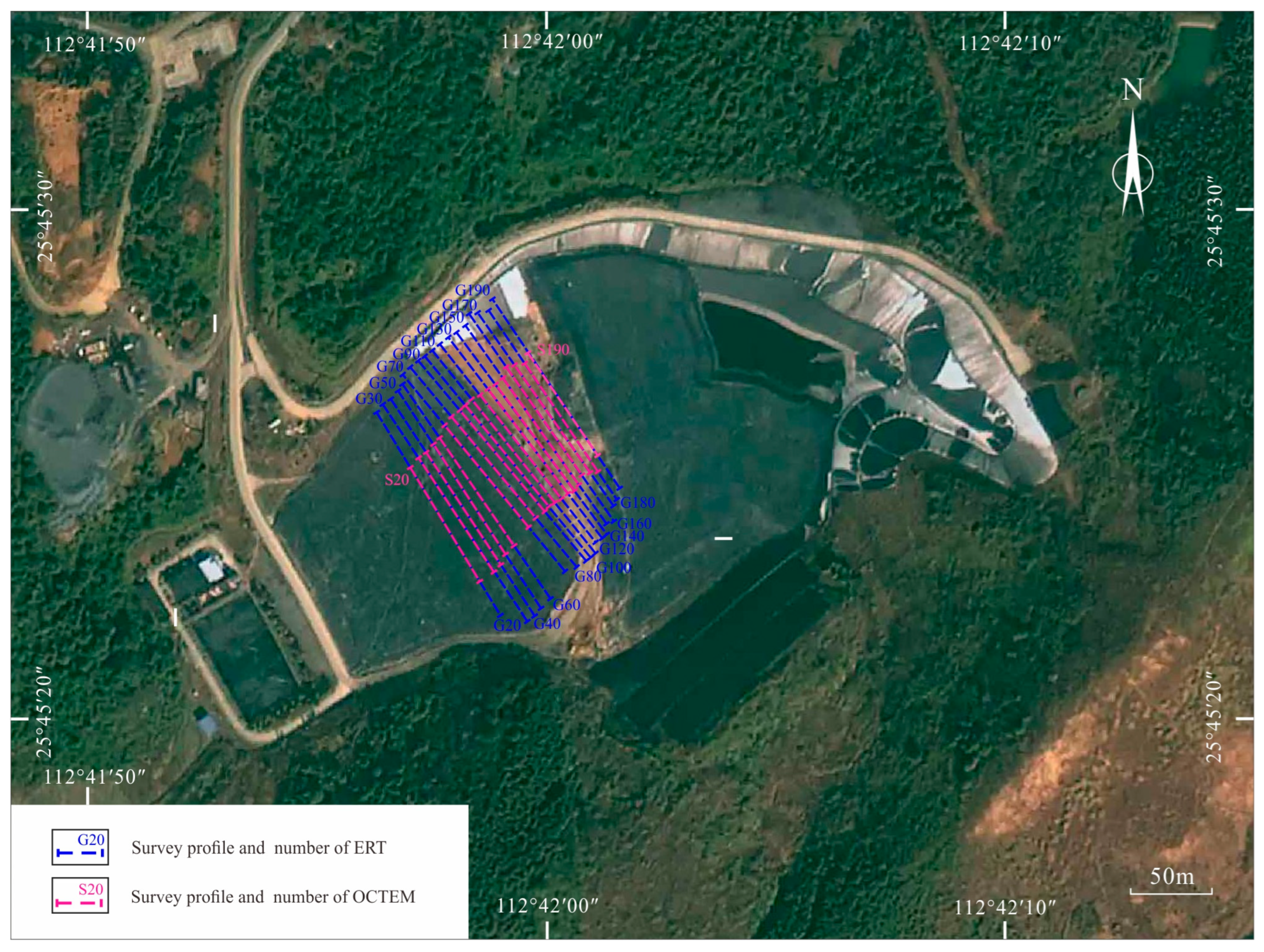
The research area was the domestic waste landfill in Chenzhou city, Guiyang county, Hunan province, China, where a population of 900,000 individuals lives. The landfill site is generally high in the east and low in the west, and surrounded by hills (Figure 1). The landfill consists of Zones A and B. Zone A is located on the northeastern side of the landfill site, which belongs to the upper part of the river valley and has a relatively high altitude (255 m). Zone B is located on the southern and western sides of the landfill site, which belong to the lower part of the river valley and have relatively low elevation (247 m). The actual elevation of the landfill site is 230.82–263.06 m, and the maximal elevation difference is 32.24 m. The research area has a subtropical humid monsoon climate, which is characterized by warm temperatures, four distinct seasons, abundant heat, concentrated rain, changeable spring temperatures, frequent droughts in summer and autumn, a short cold period, and a long hot period. Annual rainfall is from 1992.7 to 1075.1 mm, generally about 1500 mm, and the average annual rainfall is 1363 mm. Annual rainfall is mainly concentrated in April to July, accounting for more than 60% of annual rainfall. The dry season is from September to January. The average annual temperature is 19.5 °C, the highest temperature is 41 °C, and the lowest temperature is 2 °C. Frost weather in the research area lasts for an average of 14.7 days. The first frost often occurs from late November to early December, and the last frost occurs in mid-to-late February of the following year. The annual frost-free period is 277 days.
2.1. Geological Background
The research area is located in the mid–southern section of the Qinhang junction zone, the southern end of the north–south Leiyang-Linwu tectonic belt, the middle part of the Nanling tectonic belt, and the northeastern Yanling-Chenzhou-Lanshan basement fault passing through this area. The oldest outcropping strata in the region are the Sinian system, the newest is Quaternary, and Silurian is missing. Tectonic activity in this area successively experienced Caledonian, Indosinian, and Yanshanian tectonic activities. The fold structure in this area is mainly overturned anticline and syncline composed of Devonian–Permian strata. The fold structure in this area is a complex north–south fold belt. The fault structure in the area is relatively developed, which is mainly near the north–south compression–torsional fault, followed by nearly EW tension-torsional fault, and the NW tension-torsional fault is the least developed.
The main strata exposed in the study are as follows. The Quaternary alluvial-proluvial layer located in the valley zone in the area, which is gray black, gray, yellow, and hard plastic. It is mainly composed of clay particles containing a small amount of gravel and debris, and mainly composed of limestone and sandstone with general toughness, medium dry strength, and thickness of 3.0–9.2 m. It contains plant roots within 0.4 m of its surface layer. The Quaternary slope residual layer is mainly distributed in the hillside, and is grayish yellow, yellowish brown, slightly wet, and plastic to hard plastic. Its composition is mainly silty clay and it contains strong weathering granite. The particles of the gravel are about 1~3 cm, and the content is about 10~25%. The Devonian Xikuangshan Formation is the outcropped bedrock in the area, and is grayish black cyan, and gray, partially contains carbonaceous limestone, the upper part is strongly weathered, and the fracture is relatively developed, with broken cores with thickness of 0.5–5.8 m. The lower part of the rock is relatively complete, and karst is locally developed. This layer is the main aquifer in the area with good permeability and water abundance. The lower carboniferous Yanguan stage limestone is mainly distributed in the northwest and southeast of the landfill. It is moderately weathered, containing carbonaceous with an aphanitic structure and calcite mesh filling. The landfill site is located in the core of the small syncline structure, and the fault structure is not developed.
On the basis of the geological conditions of the landfill site, sand, gravel, and especially clay minerals provide a better base liner to prevent possible leakage to the surrounding environment [5]. The sand and gravel layer provide the drainage channel for the landfill leachate collection [38]. Furthermore, the geological structure of the landfill location is not developed, and the syncline structure is helpful in containing the leachates [15].
2.2. Basic Physical Structure of the Domestic Waste Landfill
Generally, the physical layered structure of a landfill mainly consists of a top capping system, a bottom liner system, and a lower bedrock layer. The waste landfill in the research area is currently in use and has not been closed; the capping system on the top has not yet been completed (Figure 2). The capping system of the landfill in the research area is only covered with an impermeable layer consisting of a geomembrane and a small amount of clay on the surface to prevent surface water infiltration as much as possible; a layer of landfill domestic waste ranging from a few to a dozen meters’ thickness is below the impermeable layer. The bottom liner system is an impermeable layer located at the bottom and around the landfill consisting of an absorption and a filtration layer, a leachate collection layer, HDPE, and a clay layer from top to the bottom. It collects and isolates the leachate from waste, and prevents it from leaking downward. The lower bedrock layer is mainly composed of clay layer and bedrock, with 10–20 m clay thickness; the bedrock is the limestone of the Devonian Xikuangshan Formation and the lower Carboniferous Yanguan Stage. The stratum dips to the NW with a small dip angle.
2.3. Geophysical Properties
The composition of domestic waste is complex and varies from region to region. Generally, the composition of waste in cottage areas is mainly ash, followed by food, paper, and plastic. Residents living in areas with buildings mainly produce domestic waste. China’s urban domestic waste has the basic characteristics of a mixed composition, high moisture, and a low calorific value. Garbage bags contain ash, plastic, and paper. The composition of domestic waste sites in the research area is extremely complex, with the waste composition of both building and cottage areas, and moisture content of above 50%.
According to previous physical-property data [45,46], combined with the results of field experiments in the research area, waste bodies are mostly domestic waste, which is easily corroded to produce leachate. The leachate has high conductivity and low-resistance with resistivity values of 1~100 Ω-m. The impermeable system is mainly composed of materials nonwoven geotextiles, a gravel layer, HDPE, and a clay layer with resistivity values of about 200 Ω-m. The lower part of the antiseepage layer limestone, showing high resistance characteristics, has resistivity generally in the range of 300–2500 Ω-m. The electrical difference between the layers of the landfill in the research area is obvious, and prerequisites for electrical exploration are available.
3. Experimental Methods
3.1. Electrical Resistivity Tomography Method
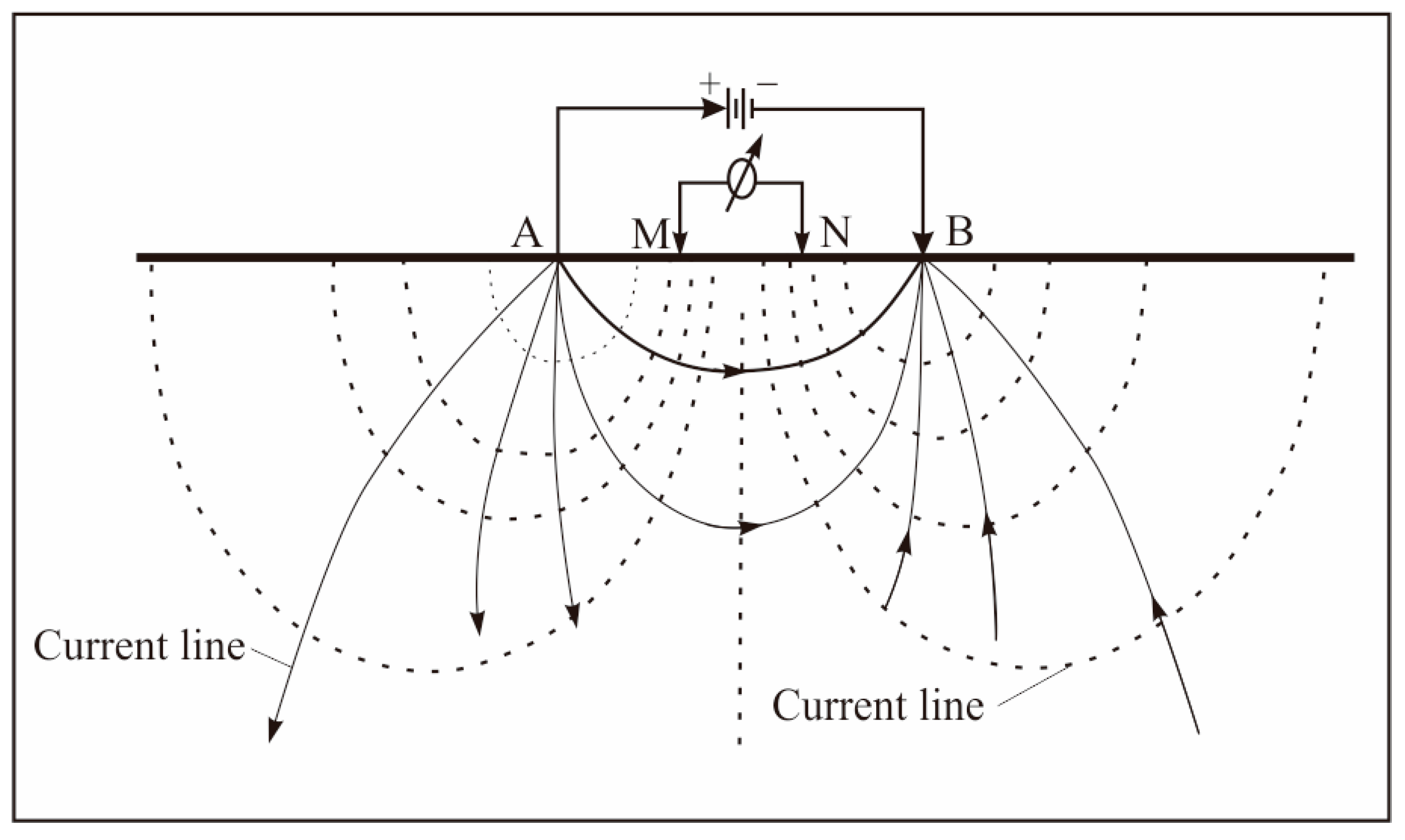
Electrical resistivity tomography (ERT) is a noninvasive geophysical method that measures the spatial distribution of the resistivity of a geological body. A total of 18 electrical resistivity survey lines with a direction of 140° and distance of 10 m were set up in the landfill, totaling 288 detection points. The ERT instrument model used in this study was SyscalProSwitch-48, IRIS Instruments. The SyscalPro was equipped with a 10-channel data receiver connected to 4 electrodes through cables (Figure 3). It works by supplying power to two powered electrodes, A and B, and measuring the potential difference between two potential electrodes, M and N, to perform resistivity measurements [34]. The use of four electrodes for measurements minimizes the effect of contact resistance at the interface between the soil pore water and the electrodes [46,47]. One resistivity data were obtained for each four-electrode combination measurement, and the location and depth of measurement points were determined via the distance between the powered electrodes and the type of the electrode device.
This system was characterized by large storage capacity, accurate and fast measurements, easy operation, and stable and reliable performance, which meet the relevant specifications and design requirements. Resistivity measurements along a measuring line with different combinations of four electrodes were performed to obtain the two-dimensional resistivity distribution of the geological body. Resistivity measured with the electrical resistivity tomography method is called apparent resistivity ρ, expressed as follows:
where I is the input current between the power supply electrodes A and B, ∆V is the potential difference between potential electrodes M and N, α is the electrode spacing, and the unit of apparent resistivity ρ is Ohm∙m.
3.2. Opposing-Coil Transient Electromagnetic Method
The opposing-coil transient electromagnetic method uses an underground return source to send a primary-step electromagnetic field to the subsurface to detect the electrical characteristics of the subsurface medium by detecting the response of the secondary induction field generated by turning off the excitation source [48,49]. Unlike the conventional transient electromagnetic method, the opposing-coil transient electromagnetic method is sent using a dual-coil source in which Current I of the same magnitude and opposite direction is simultaneously supplied to the dual-coil source and measured after the current is turned off. The magnetic lines of the force at the receiving coil were horizontal and had a vertical magnetic field of 0 before and after shutdown, with a magnetic flux of 0 in the plane of that position and a vertical magnetic field in other planes. The formation of a zero-flux surface can eliminate the effect of primary field shutdown at any moment; by measuring at the zero-flux position, it can eliminate the blind spot and detect shallow underground spaces. Figure 4 shows the placement of the center-return device of the opposing-coil transient electromagnetic method.
Field source analysis was performed for the oppposing-coil transient electromagnetic method, and a column coordinate system with the center of the horizontal current loop as the origin was established (unit vectors uρ, uθ, and uz). We used the vector superposition principle to obtain the equation for the primary field of equivalent inverse flux transient electromagnetic method 2 [50]:
where d is the distance between the transmitting coil and the receiving coil, and B is the magnetic induction intensity. The secondary opposing-coil transient electromagnetic method field can be calculated using the superposition principle, which is calculated by referring to the algorithm of Coggon [51,52,53], starting from the Maxwell spin equation shown as Equation (3):
Consider the following boundary conditions:
where H is the magnetic field strength; E is the electric field strength; is the current density; ω is the dielectric constant; t is time; δ(x) is the pulse function; is the magnetic moment of the electric or magnetic field; ω(t) is the source current waveform.
The transient electromagnetic response of an arbitrary geoelectric model could be obtained by solving the magnetic field using the finite element method, of which the implementation is found in the literature [19].
4. Results and Discussion
4.1. Electrical Resistivity Tomography Method
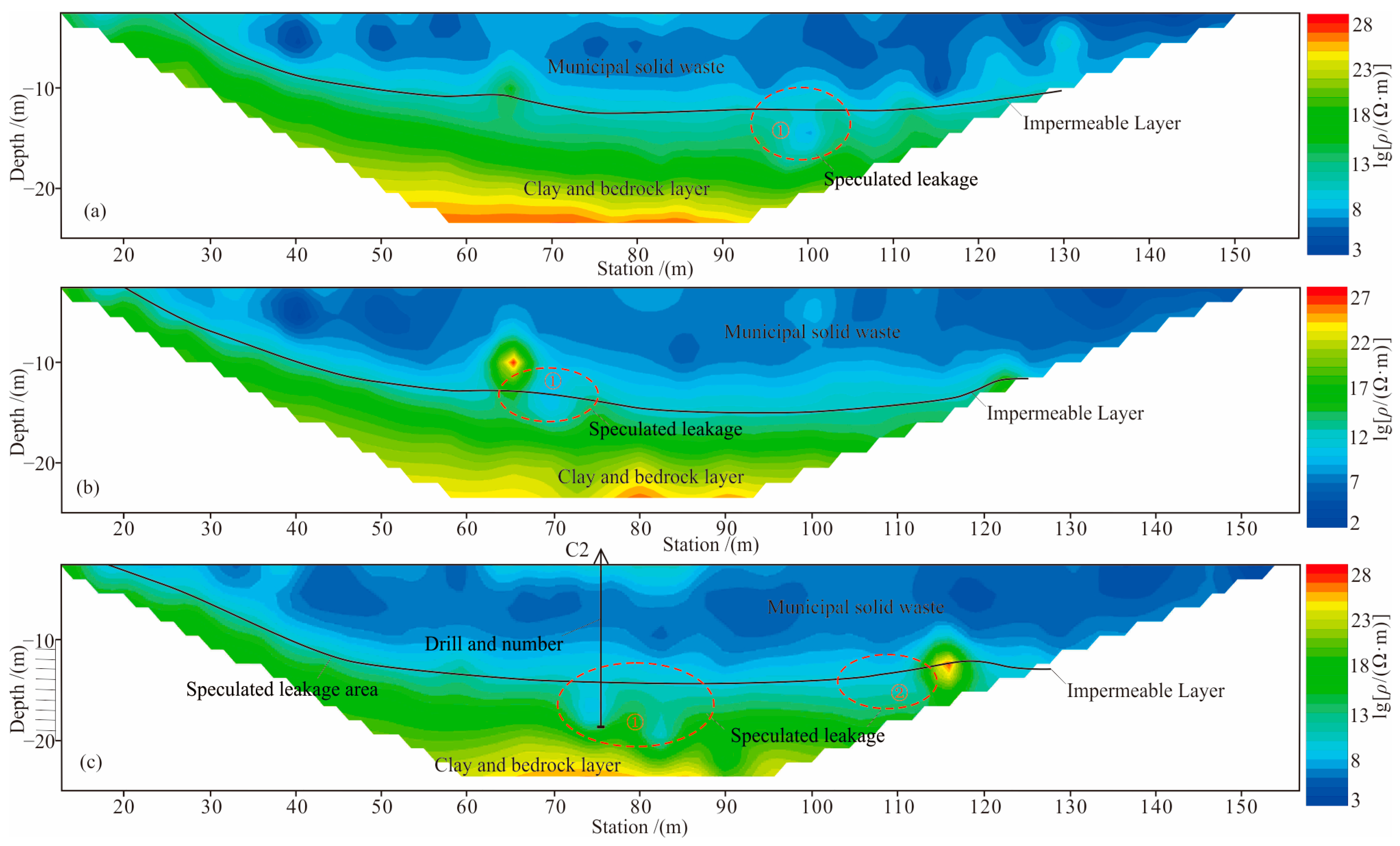
After preprocessing the original data, the resistivity inversion section was obtained by using RES2DINV software. The inversion section was inferred and interpreted according to the electrical characteristics. The inversion section showed uniformly changed resistivity and an obviously layered law. The shallow part of the inversion section was the low-resistivity domestic waste layer. The middle part was the medium-resistivity impervious layer and the Quaternary sedimentary strata. The lower part was the high-resistivity limestone of the Xikuangshan Formation of the Devonian System. In the longitudinal direction, the resistivity of the inversion section showed an obvious low–medium–high three-layer electrical structure, which was in good agreement with the hierarchical structure of the physical properties of the landfill site (Figure 5).
The resistivity of the domestic waste leachate was very low, so a low-resistivity anomaly could be observed in the seepage area, and a funnel-shaped low-resistivity anomaly appeared at the bottom or lower part of the inversion section impervious layer. In this research, obvious ground resistivity anomalies were observed in the depth of resistivity inversion sections of the G100, G110 and G120 lines (Figure 5). For example, there was an obvious low-resistivity anomaly at 100 m depth of the G100 line with a depth of 8–15 m and sectional width of about 10 m (Figure 5a). There was an obvious low-resistivity anomaly at 70 m depth of the G110 line with a depth of 10–15 m and a sectional width of about 10 m (Figure 5b). There were two low-resistivity anomalies at 80 and 110 m depth of the G120 line with a depth of 12–22 m. The sectional widths were about 20 and 10 m, respectively (Figure 5c).
4.2. Opposing-Coil Transient Electromagnetic Method
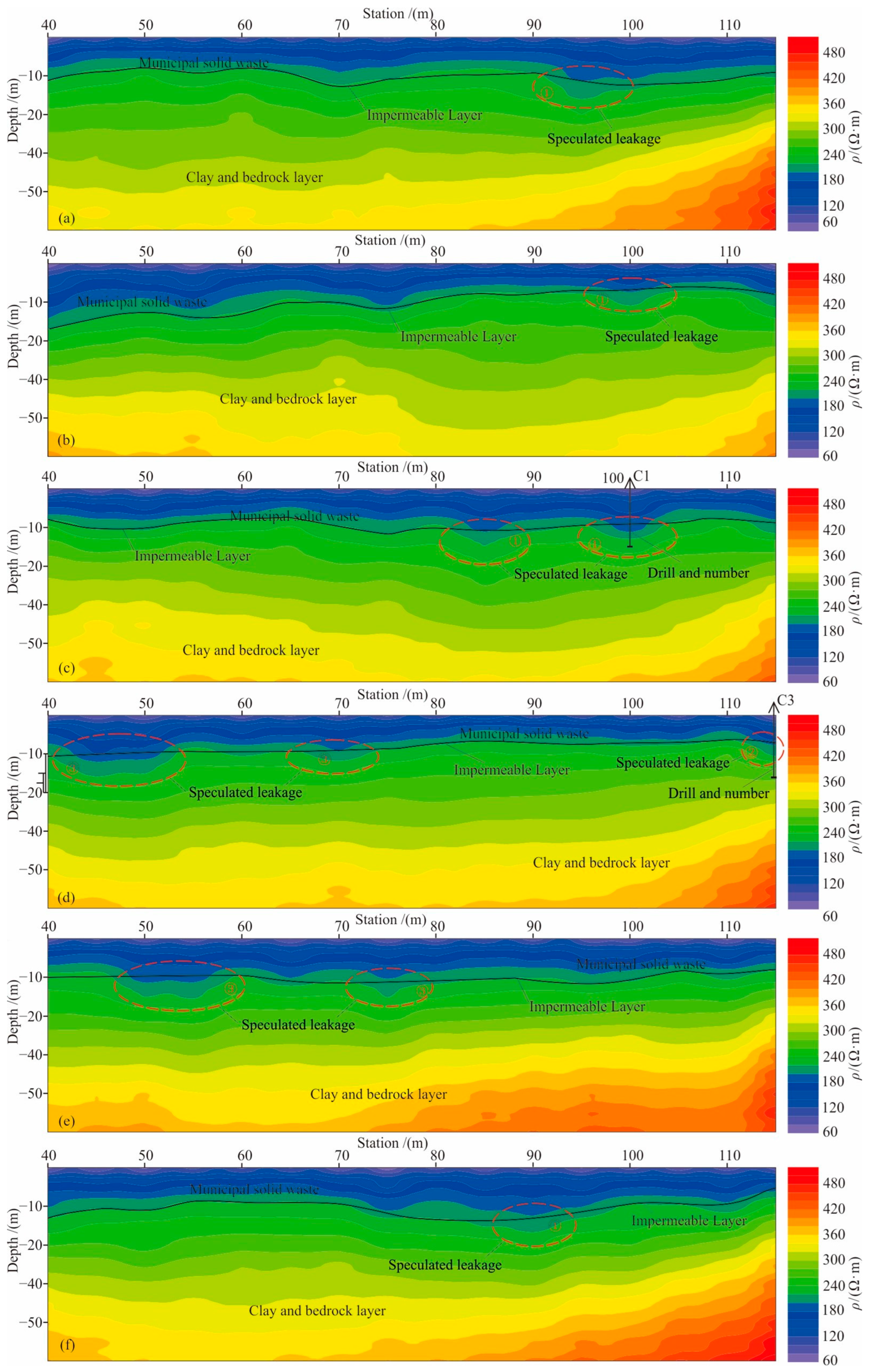
On the basis of the electrical resistivity tomography method, we performed research on the opposing-coils transient electromagnetic method. Its survey line coincided with the survey line of the resistivity method, and the survey points were distributed in the range of 40–115 m. The following data were acquired in fixed-point measurement mode: measurement point distance of 10 m, the direction of 140°, emission frequency of 6.25 Hz, emission current of 10 A, off time of 50 μs, a superposition period of 200 times, 306 measurement points, and a total of 18 cross-sections. After preprocessing the original data, HPTEM Data Process software was used to invert the resistivity inversion sections, which were inferred and interpreted according to the electrical characteristics. The inversion section showed uniformly changed resistivity and an obviously layered law. The shallow part of the inversion section was the low-resistivity domestic garbage layer. The middle part was the medium-resistivity impervious layer and the Quaternary sedimentary strata. The lower part was the high-resistivity limestone of the Xikuangshan Formation of the Devonian System. In the longitudinal direction, the resistivity of the inversion section showed an obvious low–medium–high three-layer electrical structure, which was in good agreement with the hierarchical structure of the physical properties of the landfill site (Figure 6).
Compared with the electrical resistivity tomography method, the opposing-coil transient electromagnetic method was more sensitive for retrieving the longitudinal resistivity of the inversion section. Six inversion sections showed low-resistivity anomalies, namely, S90, S110, S120, S130, and S140. There was an obvious low-resistivity anomaly at 95 m depth of the S90 line with a depth of 10–20 m and a sectional width of about 10 m (Figure 6a). There was an obvious low-resistivity anomaly at 100 m depth of the S100 line with a depth of 10–15 m and a sectional width of about 10 m (Figure 6b). There were two obvious low-resistivity anomalies at 85 and 100 m depth of the S110 line with a depth of about 10–20 m and a sectional width of about 10 m (Figure 6c). There were three low-resistivity anomalies at 50, 70, and 115 m depth of the S120 line with a depth of 10–18 m. The sectional width of the low-resistivity anomaly at the 50 m measuring point was about 15 m, and the section width of the other two low-resistivity anomalies (70 and 120 m) was about 10 m (Figure 6d). There were two obvious low-resistivity anomalies in the deep part of the S130 line located at 50 and 75 m with a depth of 10–18 m and sectional widths of about 15 and 10 m, respectively (Figure 6e). There was an obvious low-resistivity anomaly at 90 m depth of the S140 line with a depth of 18–24 m and width of about 10 m (Figure 6f). These low-resistivity anomalies may have been caused by the seepage of a low-resistance leachate if the damage of the impervious layer had occurred; therefore, these low-resistance anomalies may be leakage areas.
4.3. Distribution Characteristics of the Leakage Area and Borehole Verification
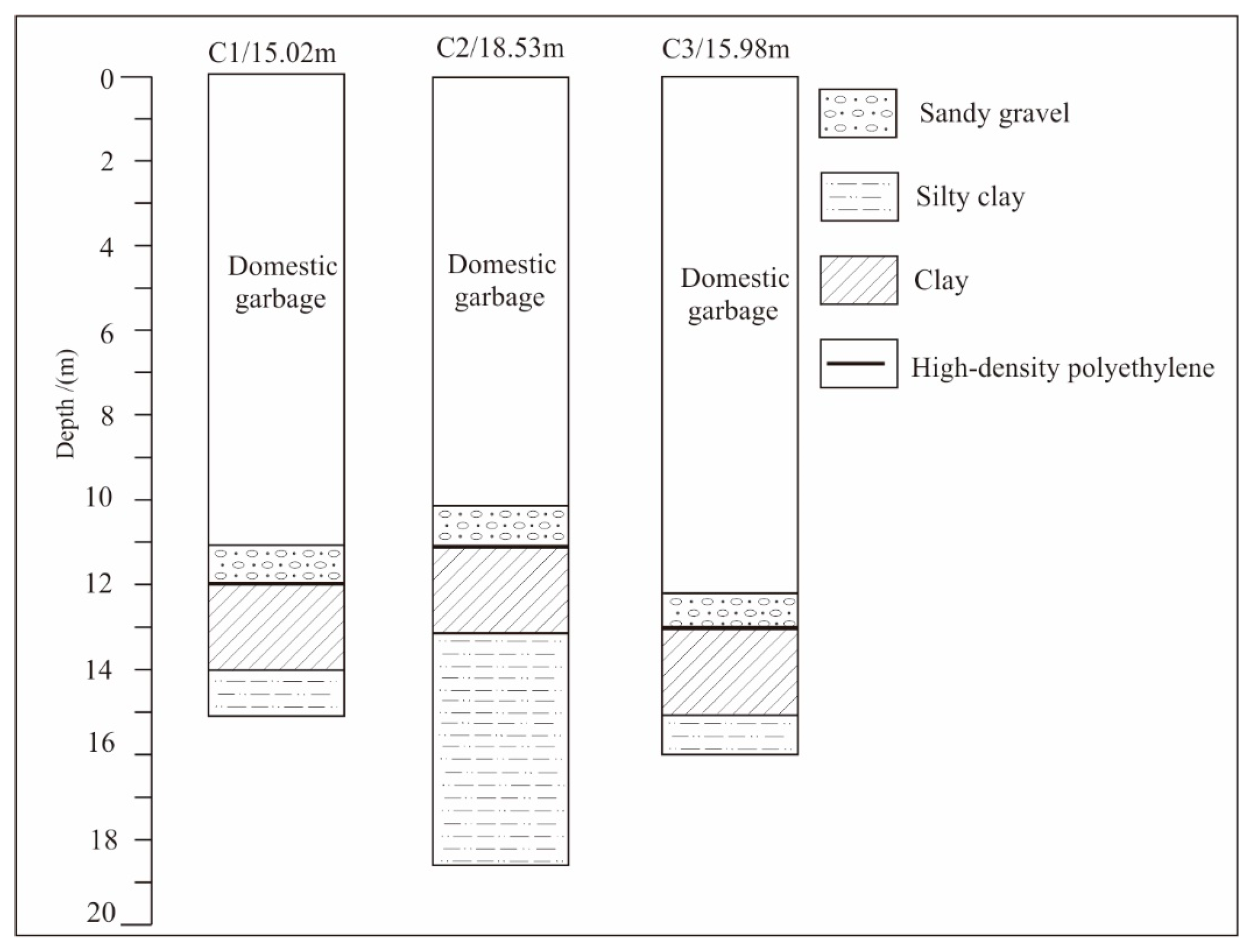
As shown in Figure 7, drilling was used to verify the low-resistivity anomaly area. C1, implemented at 100 m of the G110 line, revealed that the thickness of the domestic waste layer was 10.91 m. The depth of the gravel and clay layers of the antiseepage system was 10.91–14.10 m with a thickness of about 3.19 m. The deep part showed obvious leachate infiltration and was mainly dark brown silty clay (Figure 6c). C2 and C3 were drilled at 75 and 115 m of the G120 line. The thickness of the domestic waste layer exposed by C2 was 10.10 m. The gravel and clay layers of the antiseepage system were at 10.10–13.21 m with a thickness of 3.11 m. The deep part showed obvious infiltration and was dark brown silty clay (Figure 6c). The thickness of the domestic waste layer exposed by C3 was 12.23 m. The gravel and clay layers of the antiseepage system were at 12.23–15.16 m, with a thickness of about 2.96 m. The deep part showed obvious infiltration and was dark brown silty clay (Figure 6d).
The low-resistivity anomalies delineated with the electrical resistivity tomography method and opposing-coil transient electromagnetic method were consistent each other. The longitudinal resistivity of the opposing-coil transient electromagnetic method was more sensitive, and the low-resistivity anomalies were relatively more detailed. According to the comprehensive low-resistivity anomaly obtained with the two methods and combined with the results of drilling verification, three leachate leakage areas were delineated in Zone B of the landfill (Figure 8). ① The leakage area is located in the middle of Zone B between Lines 100 and 150 with a scope of about 260 m2 and a depth of about 10–15 m; ② the leakage area is located near the drop well in the middle of Zone B between Lines 110 and 140 with a scope of about 50 m2 and a depth of about 10~15 m; ③ the leakage area is located at the northwestern side of Leakage Area ① between Lines 120 and 140 with a scope of about 120 m2 and a depth of about 10~15 m.
5. Conclusions
- (1)
- The inversion sections of the electrical resistivity tomography method and opposing-coil transient electromagnetic method showed a clear low–middle–high resistivity spectrum in the longitudinal direction corresponding to an upper landfill layer, impermeable bottom layer, and the lower part of the argillaceous sandstone. The anomalous area of the pollution plume was observed at the bottom of the leakage area, and the gradually decreased concentration reflected the characteristics of pollution diffusion.
- (2)
- On the basis of the characteristics of the low-resistance anomalies of the inversion section found with the electrical resistivity tomography method and opposing-coil transient electromagnetic method, three low-resistance anomalous areas were delineated in Zone B of the landfill that were identified as impermeable layer seepage areas after being verified using drilling.
- (3)
- The opposing-coil transient electromagnetic method is more sensitive to abnormal changes in resistivity, and is accurate and effective for landfill leakage detection. OCTEM has broad application prospects in landfill leakage detection.
- (4)
- Future studies could focus on the exposure of subsurface information obtained with this study by using the ETR and OCTEM methods. Various exploration methods such as trail trenches and drilling could be used to determine whether the zone was accurately detected or not. Anti-seepage measures could also be taken to prevent possible leakage in the landfill.
Author Contributions
Writing—original draft, Y.L. (Yulong Lu); Writing—review & editing, Y.L. (Yang Liu); Project administration, C.C.; Methodology, J.T.; Software, Z.G. Data curation, H.L. All authors have read and agreed to the published version of the manuscript.
Funding
This research was supported by the Natural Science Foundation of Hunan Province (grant no. 2022JJ30244), the Research Project of Teaching Reform of Hunan Province (grant no. HNJG-2022-0790), the Research Foundation of the Department of Natural Resources of Hunan Province (grants no. 2022-25 and 2020-04), the Key Team Project of Science and Technology Innovation in Xiangtan City (grant no. ZY-CXTD20221003), and the Key Technology and Application of Groundwater Detection in the Arid Area of Hunan Province (grant no. 2023-24).
Data Availability Statement
No new data were created or analyzed in this study. Data sharing is not applicable to this article.
Conflicts of Interest
The authors declare no conflict of interest.
References
- Huangpu, H.H.; Li, H.Y. Analysis of the factors affecting the production of municipal solid waste. Sci. Technol. Manag. 2018, 20, 44–49. [Google Scholar]
- Xiang, R.; Lei, G.Y.; Xu, Y.; Zhou, Q.; Liu, Y.Q.; Dong, L.; Liu, J.C.; Huang, Q.F. Aging Behaviors of HDPE geomembrane in Landfill environment and its impact on pollution risk of surrounding groundwater. Res. Environ. Sci. 2020, 33, 978–986. [Google Scholar]
- Wang, Q. What causes landfill leakage? Environ. Econ. 2015, 21, 27. [Google Scholar]
- Yuan, W.X.; Chen, S.P.; Tai, J.; Song, L.J. Present situation, problems and development countermeasures of landfill in China. Environ. Sanit. Eng. 2016, 24, 8–11. [Google Scholar]
- Liu, Y.; Bouazza, A.; Gates, W.P.; Rowe, R.K. Hydraulic performance of geosynthetic clay liners to sulfuric acid solutions. Geotext. Geomembr. 2015, 43, 14–23. [Google Scholar] [CrossRef]
- Wang, L.Q.; Li, X.M.; Zhu, F.H. Current situation of municipal solid wastes disposal and development proposals in China. Environ. Pollut. Control. 2015, 37, 106–109. [Google Scholar]
- Li, Y.C.; Xu, Z.; Ma, H.; Hursthouse, A.S. Removal of Manganese (II) from acid mine wastewater: A review of the challenges and opportunities with special emphasis on Mn-Oxidizing bacteria and microalgae. Water 2019, 11, 2493. [Google Scholar] [CrossRef]
- Meng, D.; Li, J.; Liu, T.; Liu, Y.; Yan, M.; Hu, J.; Li, H.; Liu, X.; Liang, Y.; Liu, H.; et al. Effects of redox potential on soil cadmium solubility: Insight into microbial community. J. Environ. Sci. 2019, 75, 224–232. [Google Scholar] [CrossRef]
- Deng, R.J.; Jin, C.S.; Ren, B.Z.; Hou, B.L.; Hursthouse, A.S. The potential for the treatment of antimony-containing wastewater by iron-based adsorbents. Water 2017, 9, 794. [Google Scholar] [CrossRef]
- Wang, Z.; Liao, L.; Hursthouse, A.; Song, N.; Ren, B.Z. Sepiolite-based adsorbents for the removal of potentially toxic elements from water: A strategic review for the case of environmental contamination in Hunan, China. Int. J. Environ. Res. Public Health 2018, 15, 1653. [Google Scholar] [CrossRef]
- Zhao, Y.L.; Zhang, C.S.; Wang, Y.X.; Lin, H. Shear-related roughness classification and strength model of natural rock joint based on fuzzy comprehensive evaluation. Int. J. Rock Mech. Min. Sci. 2021, 137, 104550. [Google Scholar] [CrossRef]
- Xie, Q.; Ren, B.Z.; Hursthouse, A.S.; Shi, X.Y. Effects of mining activities on the distribution, controlling factors, and sources of metals in soils from the Xikuangshan south mine, Hunan Province. Integr. Environ. Assess. Manag. 2022, 18, 748–756. [Google Scholar] [CrossRef]
- Feng, H.; Liu, F.; Luo, P.; Xie, G.; Xiao, R.; Hu, W.; Peng, J.; Wu, J. Performance of integrated ecological treatment system for decentralized rural wastewater and significance of plant harvest management. Ecol. Eng. 2018, 124, 69–76. [Google Scholar]
- Zhao, Y.L.; Zhang, L.Y.; Liao, J.; Wang, W.J.; Liu, Q.; Tang, L.M. Experimental study of fracture toughness and subcritical crack growth of three rocks under different environments. Int. J. Geomech. 2020, 20, 04020128. [Google Scholar] [CrossRef]
- Liu, Y.; He, B.; Xie, J.; Lu, Y.; Zhang, L. Compatibility of geosynthetic clay liners at different temperatures. J. Environ. Prot. Ecol. 2021, 22, 2295–2306. [Google Scholar]
- Pandey, L.M.S.; Shukla, S.K. An insight into waste management in Australia with a focus on landfill technology and liner leak detection. J. Clean. Prod. 2019, 225, 1147–1154. [Google Scholar] [CrossRef]
- Tang, L.; Tang, X.W.; Liu, Y.; Qu, S.X. Prediction of pore size characteristics of woven slit-film geotextiles subjected to unequal biaxial tensile strains. Geotext. Geomembr. 2020, 48, 724–734. [Google Scholar] [CrossRef]
- Zhang, J.; Deng, R.J.; Ren, B.Z.; Hou, B.L.; Hursthouse, A. Preparation of a novel Fe3O4/HCO composite adsorbent and the mechanism for the removal of antimony (III) from aqueous solution. Sci. Rep. 2019, 9, 13021. [Google Scholar] [CrossRef]
- Liu, Y.; Hao, Y.; Lu, Y. Improved design of risk assessment model for PPP project under the development of marine architecture. J. Coast. Res. 2018, 83, 74–80. [Google Scholar] [CrossRef]
- Zhu, G.; Wang, C.; Dong, X. Fluorescence excitation-emission matrix spectroscopy analysis of landfill leachate DOM in coagulation-flocculation process. Environ. Technol. 2017, 9, 1489–1497. [Google Scholar] [CrossRef]
- Tian, K.; Benson, C.H.; Yang, Y.M.; Tinjum, J.M. Radiation dose and antioxidant depletion in a HDPE geomembrane. Geotext. Geomembr. 2018, 46, 426–435. [Google Scholar] [CrossRef]
- Li, L.; Yu, X.; Wang, T.J.; Tan, Y.G. The in fluence analysis of Jinkou landfill on the ground water quality in Wuhan City. Environ. Pollut. Control. 2016, 38, 7–12. [Google Scholar]
- Li, Y.; Hu, X.; Ren, B.Z. Treatment of antimony mine drainage: Challenges and opportunities with special emphasis on mineral adsorption and sulfate reducing bacteria. Water Sci. Technol. 2016, 73, 2039–2051. [Google Scholar] [CrossRef] [PubMed]
- Luo, X.; Ren, B.Z.; Hursthouse, A.S.; Thacker, J.R.M.; Wang, Z.H. Soil from an abandoned manganese mining area (Hunan, China): Significance of health risk from potentially toxic element pollution and its spatial context. Int. J. Environ. Res. Public Health 2020, 17, 6554. [Google Scholar] [CrossRef]
- Zhou, Y.; Ren, B.Z.; Hursthouse, A.S.; Zhou, S. Antimony ore tailings: Heavy metals, chemical speciation, and leaching characteristics. Pol. J. Environ. Stud. 2019, 28, 485–495. [Google Scholar] [CrossRef]
- Liu, Y.; Gates, W.P.; Bouazza, A. Acid induced degradation of the bentonite component used in geosynthetic clay liners. Geotext. Geomembr. 2013, 36, 71–80. [Google Scholar] [CrossRef]
- He, Z.; Ren, B.Z.; Hursthouse, A.; Wang, Z. Efficient removal of Cd(II) using SiO2-Mg(OH)2 nanocomposites derived from sepiolite. Int. J. Environ. Res. Public Health 2020, 17, 2223. [Google Scholar] [CrossRef]
- Zhang, Y.; Ren, B.Z.; Hursthouse, A.; Deng, R.J.; Hou, B.L. Leaching and releasing characteristics and regularities of Sb and As from antimony mining waste rocks. Pol. J. Environ. Stud. 2019, 28, 4017–4025. [Google Scholar] [CrossRef]
- Zhao, Y.L.; Luo, S.L.; Wang, Y.X.; Wang, W.J.; Zhang, L.Y.; Wan, W. Numerical analysis of karst water inrush and a criterion for establishing the width of water-resistant rock pillars. Mine Water Environ. 2017, 36, 508–519. [Google Scholar] [CrossRef]
- Yuan, Q.; Zhu, G. A review on metal organic frameworks (MOFs) modified membrane for remediation of water pollution. Environ. Eng. Res. 2021, 26, 190435. [Google Scholar] [CrossRef]
- Deng, R.J.; Shao, R.; Ren, B.Z.; Hou, B.L.; Tang, Z.E.; Hursthouse, A. Adsorption of antimony(III) onto Fe(III)-treated humus sludge adsorbent: Behavior and mechanism Insights. Pol. J. Environ. Stud. 2019, 28, 577–586. [Google Scholar] [CrossRef]
- Liu, S.; Fan, S.G.; Sun, Z.H.; Zhang, X.X. Analysis of metal ion content in different treatment stages of landfill leachate. Applied Chem. Ind. 2018, 47, 1304–1307. [Google Scholar]
- Xie, J.; Liu, Y.; Lu, Y.; Zhang, L. Application of the high-density resistivity method in detecting a mined-out area of a quarry in Xiangtan City, Hunan Province. Front. Environ. Sci. 2022, 10, 1068956. [Google Scholar]
- Lu, Y.L.; Yang, T.C.; Abdollah, T.T.; Liu, Y. Fast recognition on shallow groundwater and anomaly analysis using frequency selection sounding method. Water 2023, 15, 96. [Google Scholar] [CrossRef]
- Lu, Y.L.; Cao, C.H.; Liu, Y.Q.; Liu, Y. Study on application of comprehensive geophysical prospecting method in urban geological survey-Taking concealed bedrock detection as an example in Dingcheng district, Changde City, Hunan province, China. Appl. Sci. 2023, 13, 417. [Google Scholar] [CrossRef]
- Zhao, Y.L.; Liu, Q.; Zhang, C.; Liao, J.P.; Lin, H.; Wang, Y. Coupled seepage-damage effect in fractured rock masses: Model development and a case study. Int. J. Rock Mech. Min. Sci. 2021, 144, 104822. [Google Scholar] [CrossRef]
- Zhang, Y.; Ren, B.Z.; Hursthouse, A.; Deng, R.J.; Hou, B.L. Study on the migration rules of Sb in antimony ore soil based on HYDRUS-1D. Pol. J. Environ. Stud. 2018, 28, 965–972. [Google Scholar] [CrossRef]
- Liu, Y.; Gates, W.P.; Bouazza, A. Impact of acid leachates on microtexture of bentonites used in geosynthetic clay liners. Geosynth. Int. 2019, 26, 136–145. [Google Scholar] [CrossRef]
- Hou, B.L.; Liu, X.; Li, Z.; Ren, B.Z.; Kuang, Y. Heterogeneous fenton oxidation of butyl xanthate catalyzed by iron-loaded sewage sludge. Fresenius Environ. Bull. 2022, 31, 4125–4131. [Google Scholar]
- Zhao, Y.L.; Zhang, L.; Wang, W.; Tang, J.; Lin, H.; Wan, W. Transient pulse test and morphological analysis of single rock fractures. Int. J. Rock Mech. Min. Sci. 2017, 91, 139–154. [Google Scholar] [CrossRef]
- Hou, B.L.; Li, Z.; Deng, R.J.; Ren, B.Z. Advanced treatment of coal chemical industry wastewater by expansive flow biological aerated filter. Fresenius Environ. Bull. 2017, 26, 4517–4521. [Google Scholar]
- Shi, X.; Ren, B.Z.; Hursthouse, A. Source identification and groundwater health risk assessment of PTEs in the stormwater runoff in an abandoned mining area. Environ. Geochem. Health 2022, 44, 3555–3570. [Google Scholar] [CrossRef] [PubMed]
- Yang, X.; Liu, Y.; Yang, C. Research on the slurry for long-distance large-diameter pipe jacking in expansive soil. Adv. Civ. Eng. 2018, 9, 47–54. [Google Scholar] [CrossRef]
- Calamita, G.; Brocca, L.; Perrone, A.; Piscitelli, S.; Lapenna, V.; Melone, F.; Moramarco, T. Electrical resistivity and TDR methods for soil moisture estimation in central Italy test-sites. J. Hydrol. 2012, 454, 101–112. [Google Scholar] [CrossRef]
- Xie, Q.; Ren, B.Z. Pollution and risk assessment of heavy metals in rivers in the antimony capital of Xikuangshan. Sci. Rep. 2022, 12, 14393. [Google Scholar] [CrossRef]
- Cheng, Y.X.; Liu, H.S.; Zhao, Z.Y. Investigation of urban landfill contamination using geophysical methods. Chin. J. Eng. Geophys. 2004, 1, 26–30. [Google Scholar]
- Wang, L.; Long, X.; Wang, T.T.; Xi, Z.Z.; Chen, X.F.; Zhong, M.F.; Dong, Z.Q. Application of the opposing-coils transient electromagnetic method in detection of urban shallow cavities. Geophys. Geochem. Explor. 2022, 46, 1289–1295. [Google Scholar]
- Yang, T.C.; Gao, Q.S.; Li, H.; Fu, G.H.; Hussain, Y. New insights into the anomaly genesis of the frequency selection method: Supported by numerical modeling and case studies. Pure Appl. Geophys. 2023, 180, 969–982. [Google Scholar] [CrossRef]
- Xi, Z.Z.; Long, X.; Zhou, S.; Huang, L.; Song, G.; Hou, H.T.; Wang, L. Opposing coils transient electro-magnetic method for shallow subsurface detection. Chin. J. Geophys. 2016, 59, 3428–3435. [Google Scholar]
- Coggon, J.H. Electromagnetic and electrical modeling by the finite element method. Geophysics 1970, 36, 132–153. [Google Scholar] [CrossRef]
- Leng, J.H.; Lu, Y.L.; Li, X.Q.; Zhao, X.Y.; Liu, Y. Metallogenetic Potential of the Ziyunshan Pluton in Central Hunan, South China: Insights from Element Geochemistry of Granites. Minerals 2023, 13, 144. [Google Scholar] [CrossRef]
- Lu, Y.L.; Li, X.Q.; Liu, Y.; Leng, J.H. The Establishment of Ore-Controlling Fracture System of Baoginshan Gold Mine Based on Fracture-Tectonic Analysis. Mob. Inf. Syst. 2021, 2021, 5887680. [Google Scholar] [CrossRef]
- Key, K. MARE2DEM: A 2-D inversion code for controlled-source electromagnetic and magnetotelluric data. Geophys. J. Int. 2016, 207, 571–588. [Google Scholar] [CrossRef]
Figure 1.
Location and survey line layout of the research area (from Google Earth).

Figure 2.
Structural diagram of the landfill.

Figure 3.
Working principle of electrical resistivity tomography.

Figure 4.
Schematic of the OCTEM device.

Figure 5.
Inversion results and interpretation of ERT. (a) G100 line; (b) G110 line; (c) G120 line.

Figure 6.
Inversion result and interpretation of ERT. (a) S90 line; (b) S100 line; (c) S110 line; (d) S120 line; (e) S130 line; (f) S140 line.
Figure 6.
Inversion result and interpretation of ERT. (a) S90 line; (b) S100 line; (c) S110 line; (d) S120 line; (e) S130 line; (f) S140 line.

Figure 7.
Geological borehole column.

Figure 8.
Distribution map of the speculated leakage area with a damaged impervious layer.

Disclaimer/Publisher’s Note: The statements, opinions and data contained in all publications are solely those of the individual author(s) and contributor(s) and not of MDPI and/or the editor(s). MDPI and/or the editor(s) disclaim responsibility for any injury to people or property resulting from any ideas, methods, instructions or products referred to in the content. |
© 2023 by the authors. Licensee MDPI, Basel, Switzerland. This article is an open access article distributed under the terms and conditions of the Creative Commons Attribution (CC BY) license (https://creativecommons.org/licenses/by/4.0/).
Share and Cite
MDPI and ACS Style
Lu, Y.; Tao, J.; Cao, C.; Liu, H.; Liu, Y.; Ge, Z. Detection of Landfill Leachate Leakage Based on ERT and OCTEM. Water 2023, 15, 1778. https://doi.org/10.3390/w15091778
AMA Style
Lu Y, Tao J, Cao C, Liu H, Liu Y, Ge Z. Detection of Landfill Leachate Leakage Based on ERT and OCTEM. Water. 2023; 15(9):1778. https://doi.org/10.3390/w15091778
Chicago/Turabian StyleLu, Yulong, Jialuo Tao, Chuanghua Cao, Hanlin Liu, Yang Liu, and Zhengbin Ge. 2023. "Detection of Landfill Leachate Leakage Based on ERT and OCTEM" Water 15, no. 9: 1778. https://doi.org/10.3390/w15091778
Note that from the first issue of 2016, this journal uses article numbers instead of page numbers. See further details here.