

Improvement Design of a Two-Stage Double-Suction Centrifugal Pump for Wide-Range Efficiency Enhancement
 , and
, and
Abstract
:1. Introduction
2. Research Objective
3. Setup of Improvement Design
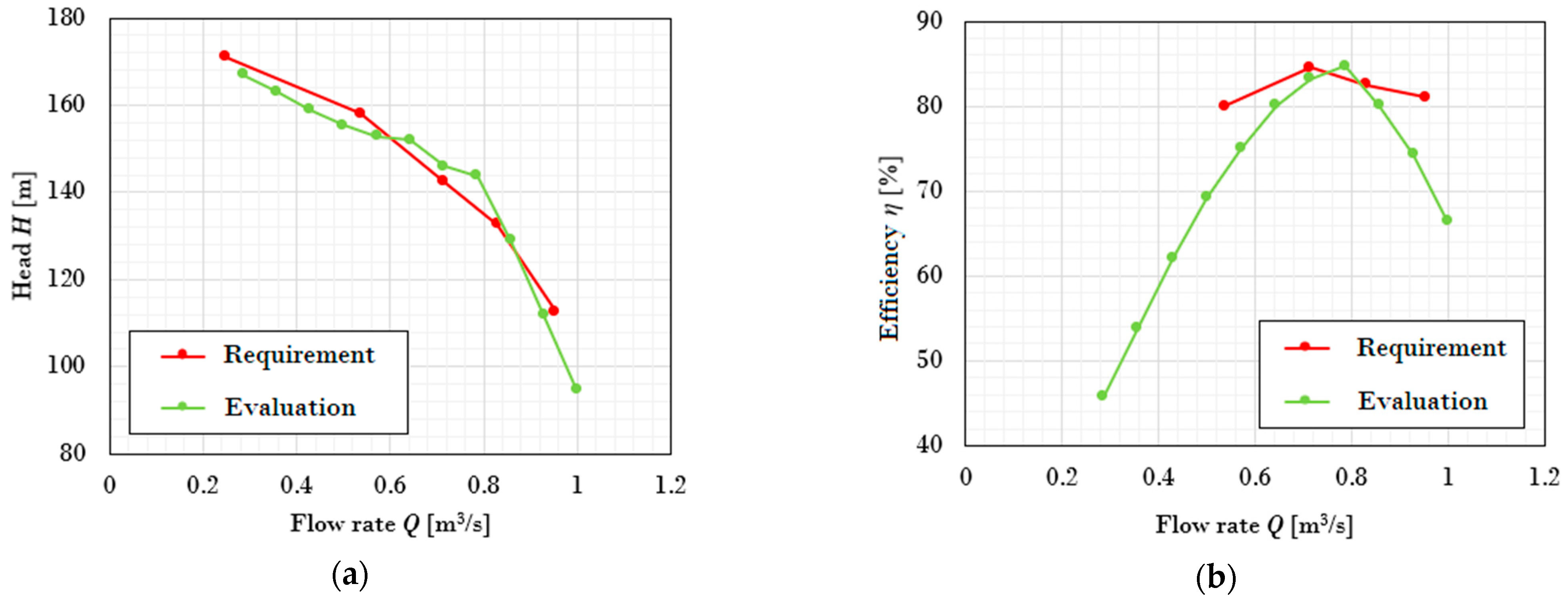
3.1. Design Target
3.2. CFD Setup
3.3. Performance Evaluation
4. Improvement History
5. Comparative Analysis
5.1. Geometry Comparison
5.2. Performance Comparison
5.3. Flow Pattern Comparison
6. Experimental–Numerical Verification
7. Conclusions
- (1)
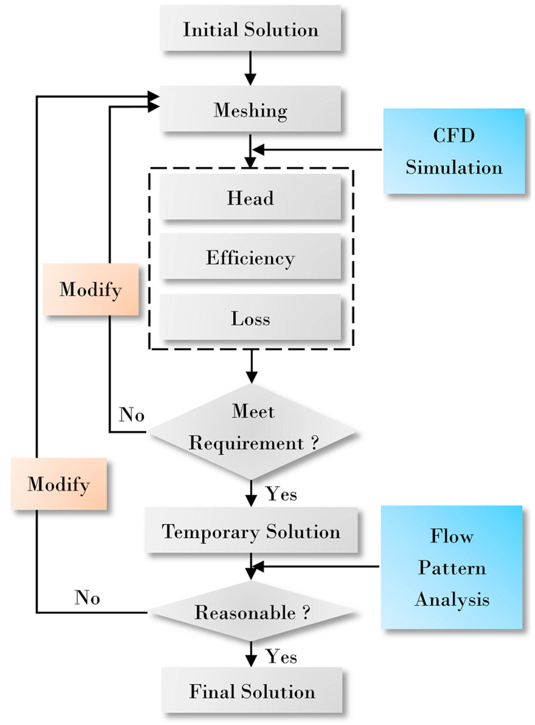
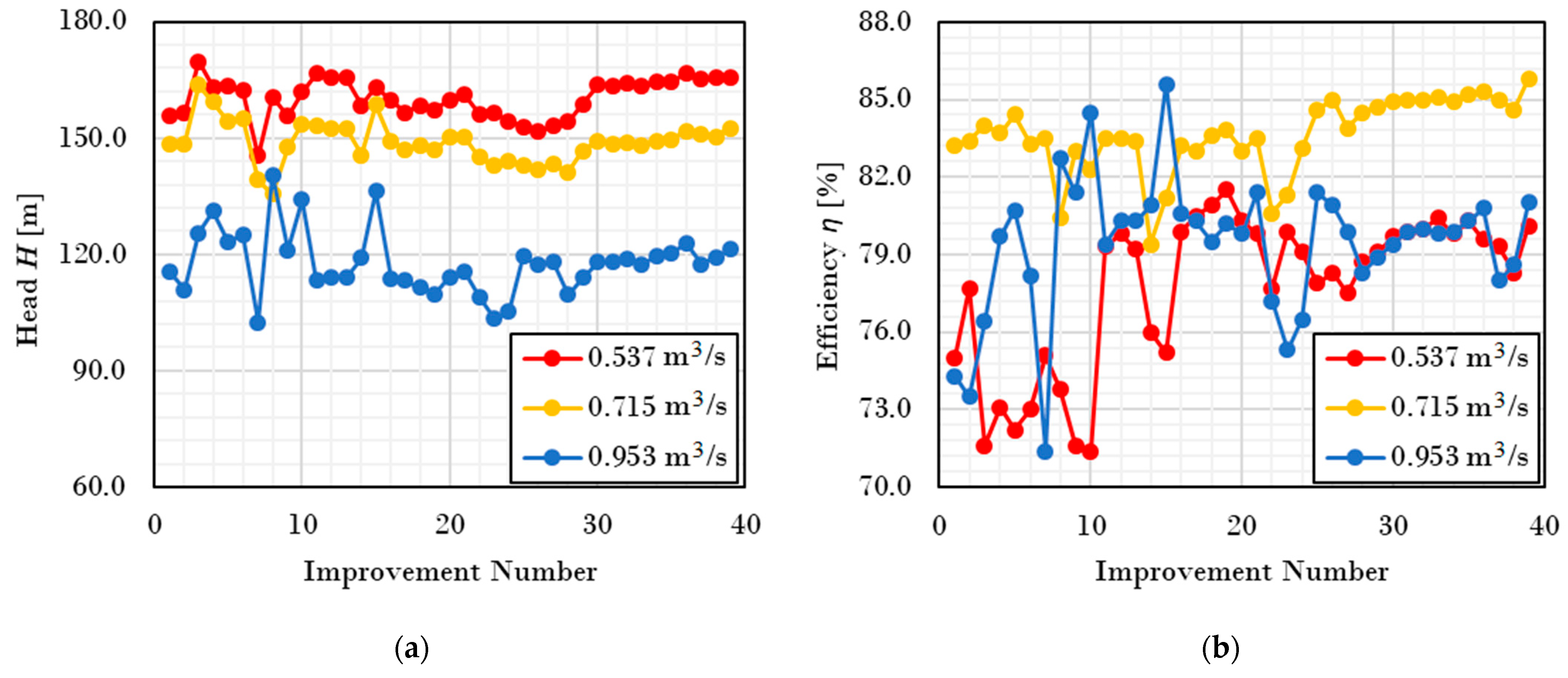
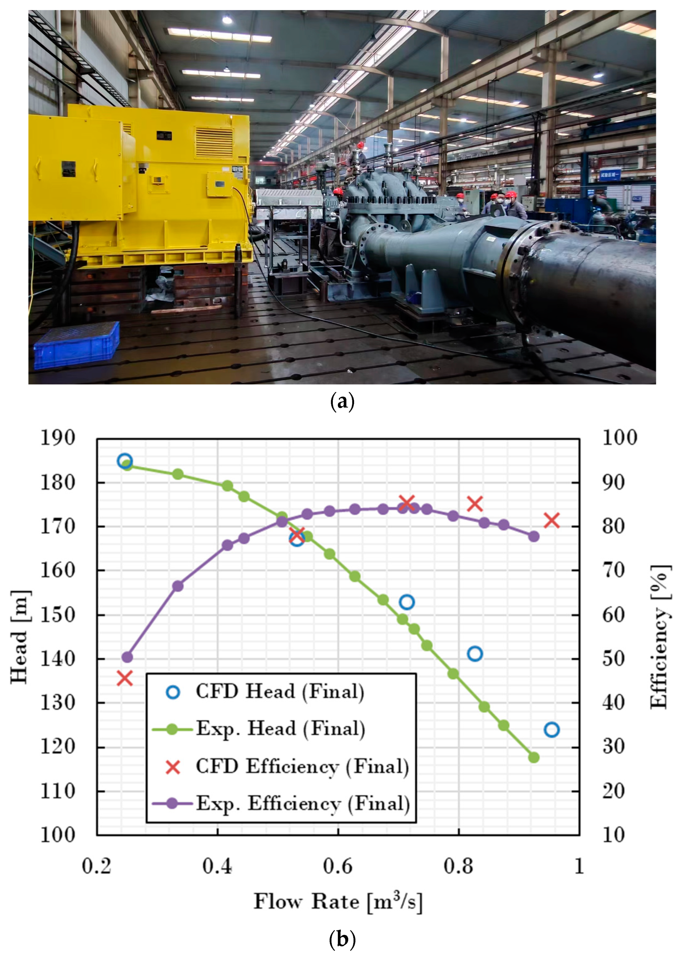
- The process of improving a pump design is mainly through the judgment of CFD on flow and pump performance and through constantly modifying the design scheme. In this study, a total of 39 improvements were made to the two-stage double-suction centrifugal pump. The efficiency of the pump increased with fluctuations in the 39 improvements, until the performance of the pump finally met the design requirements. This proved that the improvement was feasible.
- (2)
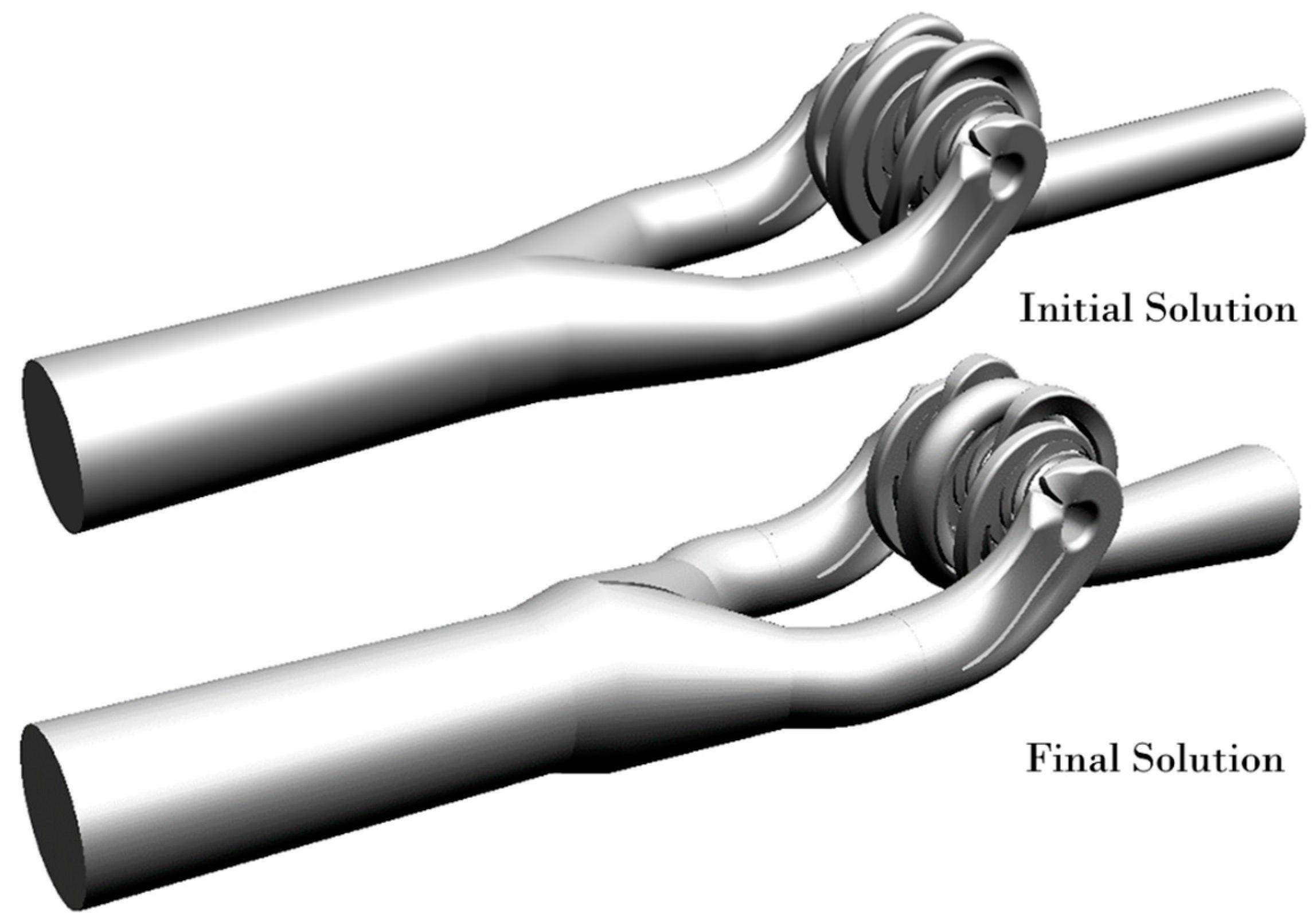
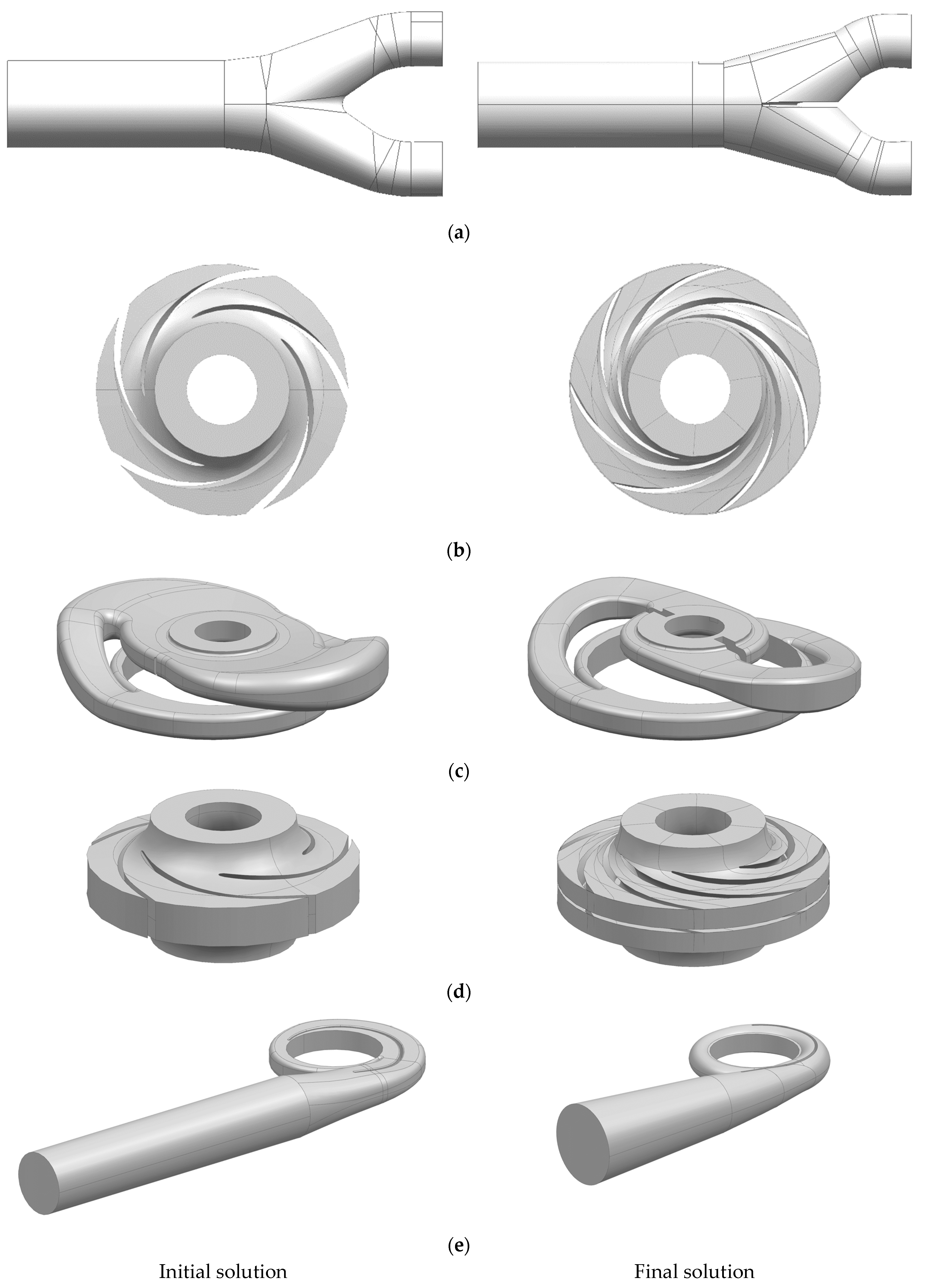
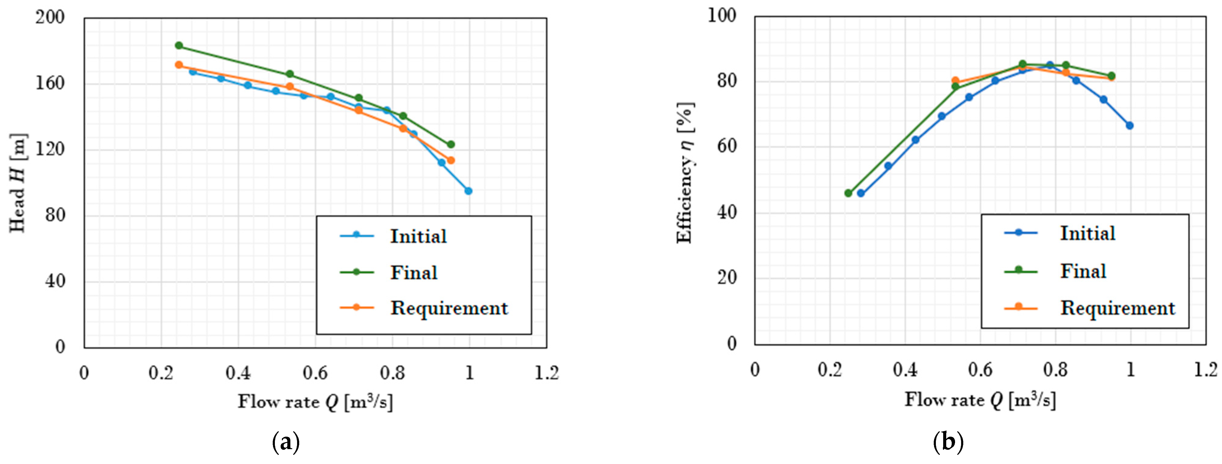
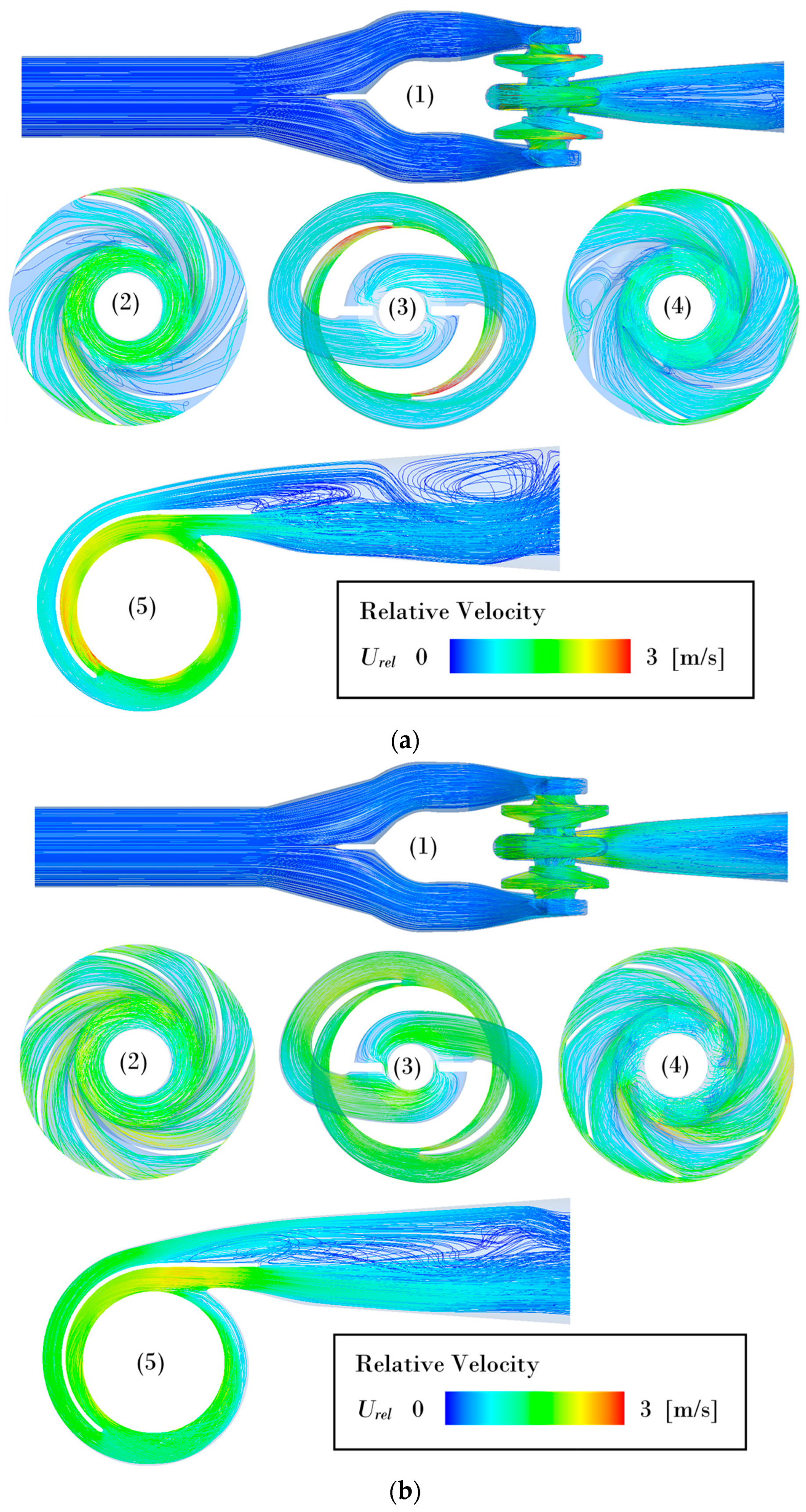
- By comparing the geometry, performance, and flow pattern of the original scheme and the final scheme of the two-stage double-suction centrifugal pump, the geometry of the final scheme was shown to be more suitable for the operating conditions, the internal flow was more stable, and the performance was significantly improved. After improvement, the pump head was increased by 10~15 m, and the efficiency was increased by 4~9% within the operation range.
- (3)
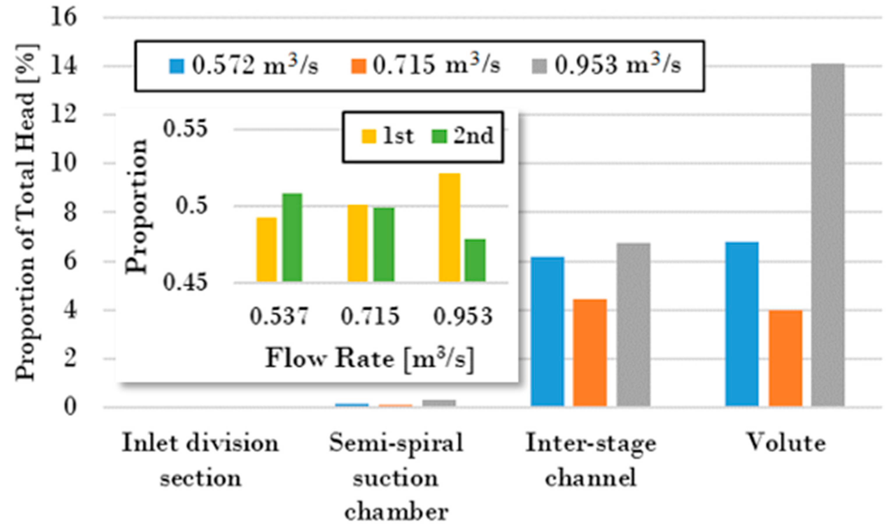
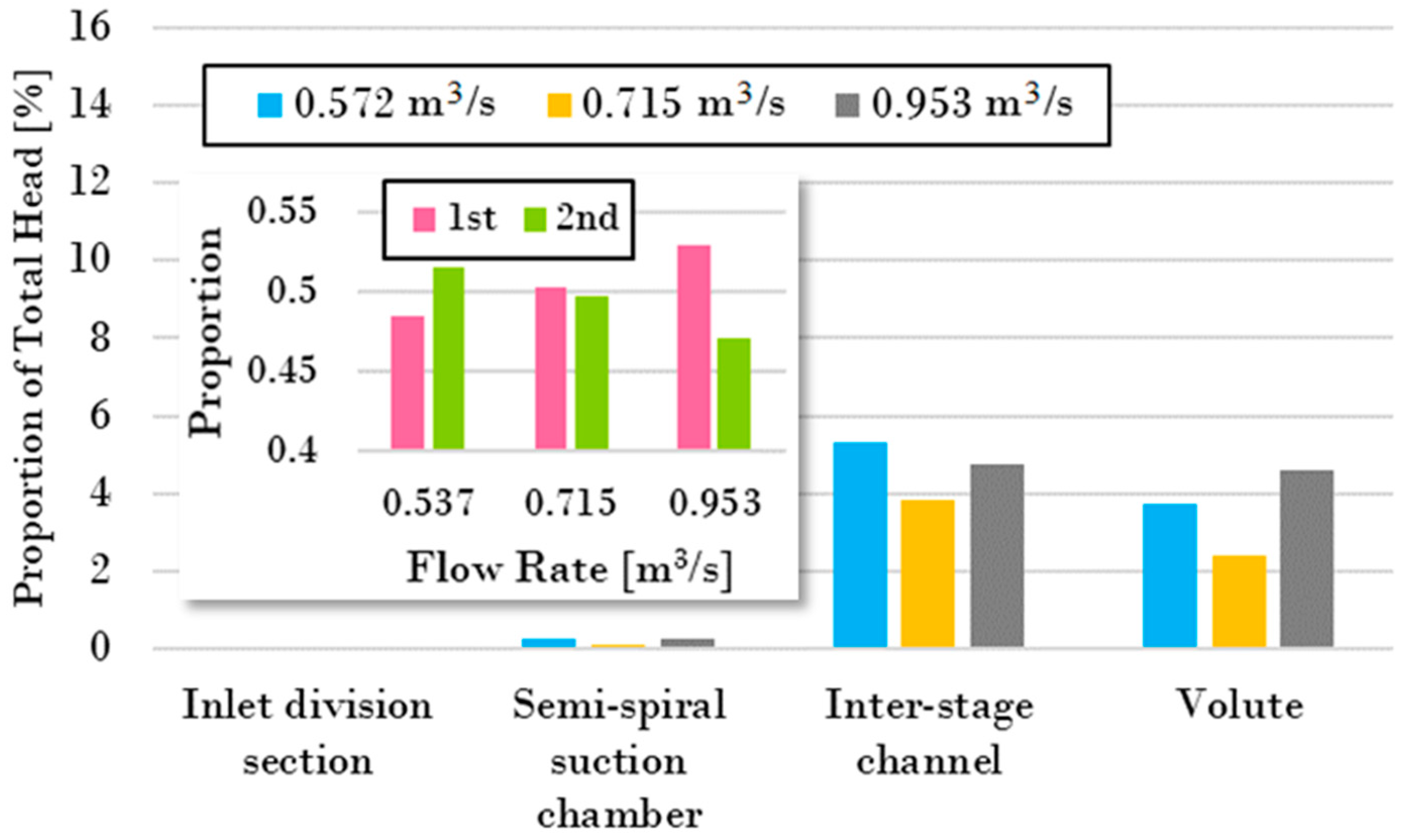
- To achieve this improvement, all the components except the semi-spiral suction chamber were modified for a better performance. The inlet division section was modified by adding a baffle at the fork. The trailing-edge blade angle of the first- and second-stage impellers were increased to a higher head. The section area of the inter-stage channel was reduced because the initial areas were too large, with vortexes and flow separation. The volute section area was increased to reduce the friction loss because of the insufficient area in the original. The hydraulic losses were reduced from about 14% to less than 6% after modification.
Author Contributions
Funding
Data Availability Statement
Conflicts of Interest
References
- Hatano, S.; Kang, D.; Kagawa, S.; Nohmi, M.; Yokota, K. Study of cavitation instabilities in double-suction centrifugal pump. Int. J. Fluid Mach. Syst. 2014, 7, 94–100. [Google Scholar] [CrossRef]
- Benigni, H. Cavitation in hydraulic machines: Measurement, numerical simulation and damage patterns. In Proceedings of the Fluids Engineering Division Summer Meeting, Online, 13–15 July 2020; Volume 83716, p. V001T01A010. [Google Scholar]
- Yao, Z.; Wang, F.; Qu, L.; Xiao, R.; He, C.; Wang, M. Experimental investigation of time-frequency characteristics of pressure fluctuations in a double-suction centrifugal pump. J. Fluids Eng. 2011, 133, 10. [Google Scholar] [CrossRef]
- Yan, H.; Heng, Y.; Zheng, Y.; Tao, R.; Ye, C. Investigation on Pressure Fluctuation of the Impellers of a Double-Entry Two-Stage Double Suction Centrifugal Pump. Water 2022, 14, 4065. [Google Scholar] [CrossRef]
- Cheng, X.; Zhang, N.; Zhao, W. Pressure fluctuation features of sand particle-laden water flow in volute of doublesuction centrifugal pump. J. Drain. Irrig. Mach. Eng. 2015, 33, 37–42. [Google Scholar]
- Sonawat, A.; Kim, S.; Ma, S.-B.; Kim, S.-J.; Lee, J.B.; Yu, M.S.; Kim, J.-H. Investigation of unsteady pressure fluctuations and methods for its suppression for a double suction centrifugal pump. Energy 2022, 252, 124020. [Google Scholar] [CrossRef]
- Zhu, D.; Xiao, R. Influence of volute section form on hydraulic performance and pressure fluctuation in double suction centrifugal pump. IOP Conf. Ser. Earth Environ. Sci. 2018, 163, 012072. [Google Scholar] [CrossRef]
- An, Y.-J.; Shin, B.R. Numerical Simulation of Centrifugal Pump with Double-Suction Impeller. AIP Conf. Proc. 2010, 1225, 456–464. [Google Scholar]
- Peng, W.; Pei, J.; Yuan, S.; Wang, J.; Zhang, B.; Wang, W.; Lu, J. Analysis of Inner Flow in a Multi-Stage Double-Suction Centrifugal Pump Using the Detached Eddy Simulation Method. Processes 2023, 11, 1026. [Google Scholar] [CrossRef]
- Škerlavaj, A.; Morgut, M.; Jošt, D.; Nobile, E. Optimization of a single-stage double-suction centrifugal pump. J. Phys. Conf. Ser. 2017, 796, 012007. [Google Scholar] [CrossRef]
- Wang, W.; Osman, M.K.; Pei, J.; Gan, X.; Yin, T. Artificial neural networks approach for a multi-objective cavitation optimization design in a double-suction centrifugal pump. Processes 2019, 7, 246. [Google Scholar] [CrossRef]
- Wang, W.; Li, Y.; Osman, M.K.; Yuan, S.; Zhang, B.; Liu, J. Multi-condition optimization of cavitation performance on a double-suction centrifugal pump based on ANN and NSGA-II. Processes 2020, 8, 1124. [Google Scholar] [CrossRef]
- Zhang, Y.; Hu, S.; Wu, J.; Zhang, Y.; Chen, L. Multi-objective optimization of double suction centrifugal pump using Kriging metamodels. Adv. Eng. Softw. 2014, 74, 16–26. [Google Scholar] [CrossRef]
- Tao, R.; Xiao, R.; Zhu, D.; Wang, F. Multi-objective optimization of double suction centrifugal pump. Proc. Inst. Mech. Eng. Part C J. Mech. Eng. Sci. 2018, 232, 1108–1117. [Google Scholar] [CrossRef]
- Wang, W.; Osman, M.K.; Pei, J.; Yuan, S.; Cao, J.; Osman, F.K. Efficiency-House Optimization to Widen the Operation Range of the Double-Suction Centrifugal Pump. Complexity 2020, 2020, 9737049. [Google Scholar] [CrossRef]
- Zhao, J.; Pei, J.; Yuan, J.; Wang, W. Energy-saving oriented optimization design of the impeller and volute of a multi-stage double-suction centrifugal pump using artificial neural network. Eng. Appl. Comput. Fluid Mech. 2022, 16, 1974–2001. [Google Scholar] [CrossRef]
- Guan, X. Modern Pumps Theory and Design; China Astronautic Publishing House: Beijing, China, 2011. [Google Scholar]
- Menter, F.R.; Kuntz, M.; Langtry, R. Ten years of industrial experience with the SST turbulence model. Turbul. Heat Mass Transf. 2003, 4, 625–632. [Google Scholar]
- Launder, B.E.; Spalding, D.B. The numerical computation of turbulent flows. In Numerical Prediction of Flow, Heat Transfer, Turbulence and Combustion; Elsevier: Amsterdam, The Netherlands, 1983; pp. 96–116. [Google Scholar]
- Wilcox, D.C. Formulation of the k–ω turbulence model revisited. AIAA J. 2008, 46, 2823–2838. [Google Scholar] [CrossRef]


| Relative Flow Rate Point | Flow Rate (m3/s) | Head Requirement (m) | Efficiency Requirement (%) |
|---|---|---|---|
| 0.30 | 0.250 | 171.0 | - |
| 0.65 | 0.537 | 158.1 | 80.0 |
| 0.86 | 0.715 | 143.4 | 84.5 |
| 1.00 | 0.830 | 132.7 | 82.5 |
| 1.15 | 0.953 | 113.6 | 81.0 |
| Component | Inlet Division Section | Semi-Spiral Suction Chambers | First-Stage Impellers | Inter-Stage Channels | Second-Stage Impeller | Volute | Total |
|---|---|---|---|---|---|---|---|
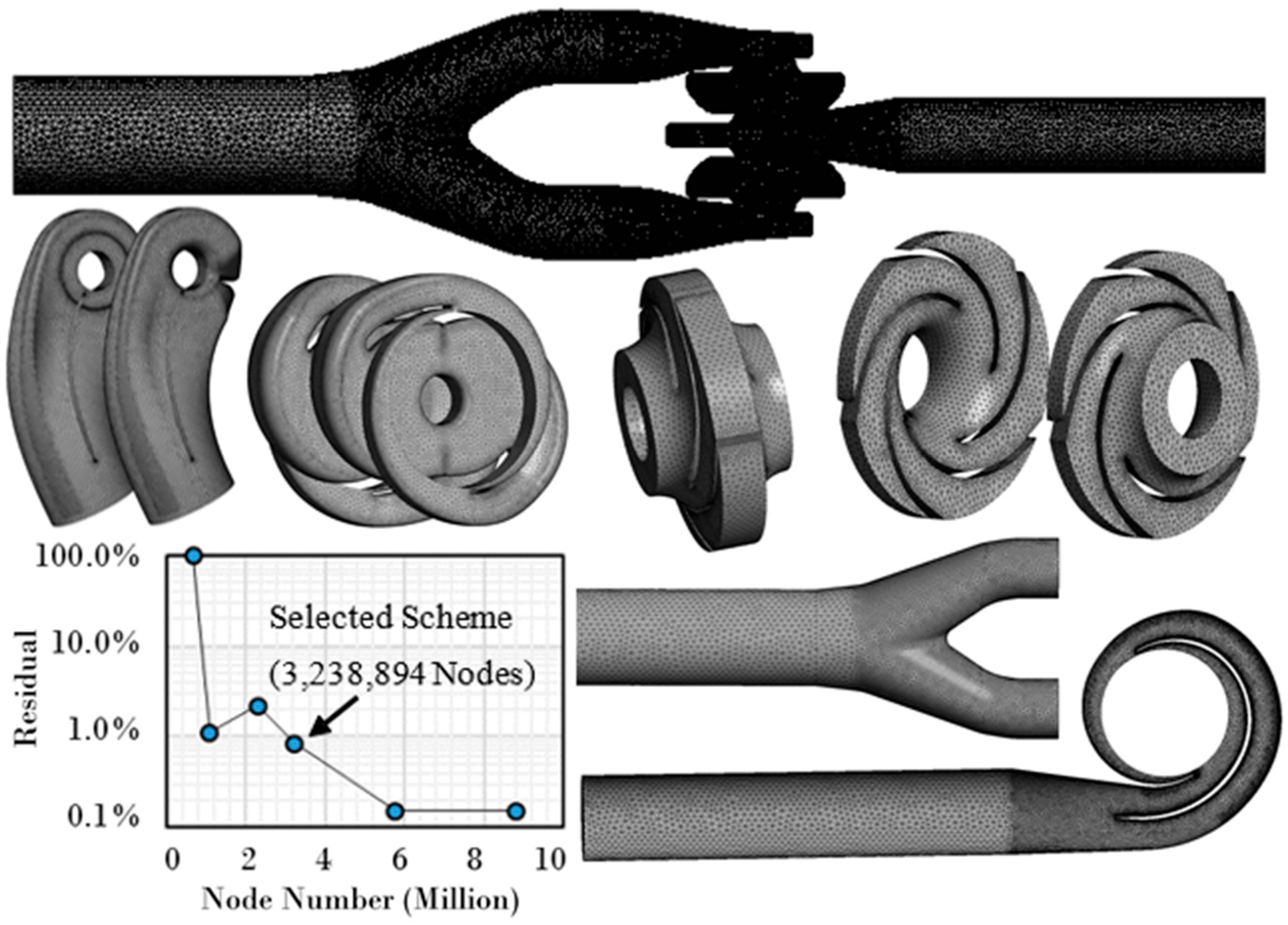
| Mesh Node Number | 227,143 | 1,061,812 | 279,590 | 794,134 | 317,946 | 558,224 | 3,238,849 |
Disclaimer/Publisher’s Note: The statements, opinions and data contained in all publications are solely those of the individual author(s) and contributor(s) and not of MDPI and/or the editor(s). MDPI and/or the editor(s) disclaim responsibility for any injury to people or property resulting from any ideas, methods, instructions or products referred to in the content. |
© 2023 by the authors. Licensee MDPI, Basel, Switzerland. This article is an open access article distributed under the terms and conditions of the Creative Commons Attribution (CC BY) license (https://creativecommons.org/licenses/by/4.0/).
Share and Cite
Zhu, D.; Hu, Z.; Chen, Y.; Wang, C.; Yang, Y.; Lu, J.; Song, X.; Tao, R.; Wang, Z.; Ma, W. Improvement Design of a Two-Stage Double-Suction Centrifugal Pump for Wide-Range Efficiency Enhancement. Water 2023, 15, 1785. https://doi.org/10.3390/w15091785
Zhu D, Hu Z, Chen Y, Wang C, Yang Y, Lu J, Song X, Tao R, Wang Z, Ma W. Improvement Design of a Two-Stage Double-Suction Centrifugal Pump for Wide-Range Efficiency Enhancement. Water. 2023; 15(9):1785. https://doi.org/10.3390/w15091785
Chicago/Turabian StyleZhu, Di, Zilong Hu, Yan Chen, Chao Wang, Youchao Yang, Jiahao Lu, Xijie Song, Ran Tao, Zhengwei Wang, and Wensheng Ma. 2023. "Improvement Design of a Two-Stage Double-Suction Centrifugal Pump for Wide-Range Efficiency Enhancement" Water 15, no. 9: 1785. https://doi.org/10.3390/w15091785